

Tallygenicom 6300 Operator Manual

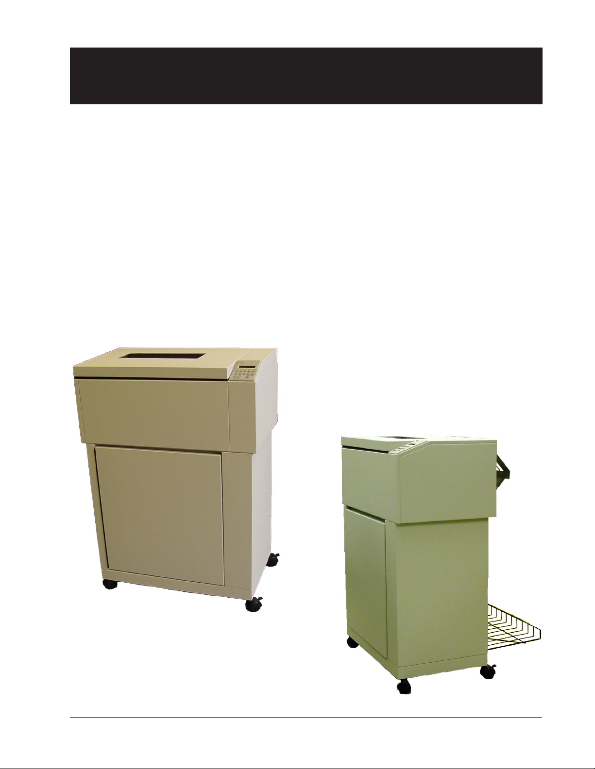
6300 Series
Operator Manual
Serial - Parallel - LAN - Twinax - Coax - IPDS
Operator Manual 1

This Manual is published by TallyGenicom for use with the computer printer described herein. Translations,
reprinting or copying by any means of this manual, complete or in part, in any different form requires our explicit
approval. TallyGenicom reserves the right to revise this manual without notice, for any reason. This includes, but
is not limited to, utilization of advances in the state-of-the-art and changes in the equipment or configuration
thereof. Liability for difficulties arising from unknown or unforeseen technical limitations is disclaimed.
FCC Statement
This equipment has been tested and found to comply with the limits for a Class A digital device, pursuant to Part
15, Subpart B of the FCC Rules. These limits are designed to provide reasonable protection against harmful
interference when the equipment is operated in a commercial environment. This equipment generates, uses,
and can radiate radio frequency energy and, if not installed and used in accordance with the instruction manual,
may cause harmful interference to radio communications. Operation of this equipment in a residential area is
likely to cause harmful interference, in which case the user will be required to correct the interference at his own
expense.
WARNING
Only trained qualified personnel may open covers or remove parts that are not explicitly shown and described in
the Operator’s Manual as being accessible to the operator.
Please Note:
Printer drivers for various operating systems are available on the Internet at our Web Page
http://www.tallygenicom.com or http://www.tallygenicom.com/worldwide or at your
TallyGenicom distributor.
ACKNOWLEDGMENTS:
“IBM” and “Proprinter” are trademarks of International Business Machines Corporation.
“DEC” is a trademark of Compaq Computer Corp.
“Printronix” and “PGL” are trademarks of Printronix, Inc.
“Epson” is a trademark of Seiko Epson Corp.
“QMS” and “Code V” are trademarks of Minolta-QMS Inc.
“HP” is a trademark of Hewlett-Packard Company.
“Genicom” is a trademark of Genicom L.L.C.
6300 Series Operator Manual
© February 2005
All rights reserved
TallyGenicom
6020 South 190th Street
Kent, Washington 98032
2 Operator Manual

Contents
Preface............................................................................................ Preface–11
Introduction.................................................................................................................... Preface–11
About This Manual......................................................................................................... Preface–12
Chapter 1 ................................................................................................... 1–13
In Chapter 1, you are instructed on how to set up your printer. You get a look at the
paper handling system, told how to install the ink ribbon, and are given a brief
introduction to the Control Panel.
Site Preparation ........................................................................................................................ 1–13
Figure 1 - 1. Shipping Screw Locations ............................................................................ 1–14
Unpacking your printer ........................................................................................................... 1–14
Repacking ................................................................................................................................. 1–14
Removing the Shipping Hardware ......................................................................................... 1–14
Rear Guide Assembly Instructions .......................................................................................... 1–15
Figure 1 - 2. Paper Stacking Chains.................................................................................. 1–15
Figure 1 - 3. Rear view, showing Serial, Parallel and Power Plugs .................................. 1–16
Connecting the I/O................................................................................................................. 1–16
Interface Connections and Powering Up ............................................................................... 1–16
Interface Connectors ............................................................................................................... 1–16
Powering Up ............................................................................................................................. 1–17
Figure 1 - 4. Power plug and on/off switch ...................................................................... 1–17
Figure 1 - 5. Inside the Lid ................................................................................................ 1–18
Paper System ............................................................................................................................. 1–18
Paper System Components ..................................................................................................... 1–18
Print Gap ................................................................................................................................... 1–19
Paper Tension ........................................................................................................................... 1–19
Tractors ..................................................................................................................................... 1–19
Figure 1 - 6. Left and Right Paper Tractors ..................................................................... 1–19
Installing the Ribbon Cartridge .............................................................................................. 1–20
Figure 1 - 7. Ribbon Cartridge .......................................................................................... 1–20
Figure 1 - 8. Installing the Ribbon Cartridge.................................................................. 1–20
Figure 1 - 9. Ribbon Shield Panels .................................................................................... 1–21
LED Indicators.......................................................................................................................... 1–22
LCD (Liquid Crystal Display)................................................................................................... 1–22
Figure 1 - 10. Control Panel .............................................................................................. 1–22
Control Panel Components .................................................................................................... 1–22
Operator Manual 3

Chapter 2 ................................................................................................... 2–25
Chapter 2 explains how to load the paper, set the print gap, and save configuration
settings.
Introduction.............................................................................................................................. 2–25
Figure 2 - 1. Inside Paper Inlet, visible when looking inside the printer cabinet. ......... 2–26
Loading Paper for Standard Printing Mode .......................................................................... 2–26
Figure 2 - 2. Paper path past the lid. .................................................................................. 2–27
Figure 2 - 3. Paper path into the wire rack. ....................................................................... 2–27
Figure 2 - 4. Column Alignment Scale............................................................................. 2–28
Figure 2 - 5. Horizontal Vernier Wheel ............................................................................. 2–28
Figure 2 - 6. Top of Form Nubbin ..................................................................................... 2–29
Print Gap Adjustment .............................................................................................................. 2–30
Gap Zone .................................................................................................................................. 2–30
Print Gap Profile Mode ............................................................................................................ 2–30
Creating a Gap Zone Profile.................................................................................................... 2–30
Using a Saved Gap Zone Profile .............................................................................................. 2–31
Fine-tuning the Automatic Print Gap Setting ........................................................................ 2–32
Figure 2 - 7. Typical Display when Print Gap Mode is set to “Auto” ................................ 2–32
Figure 2 - 8. Typical display when adjusting Print Gap .................................................... 2–33
Set Print Gap Detect Mode to Manual .................................................................................... 2–33
Setting Up Configurations ...................................................................................................... 2–34
Chapter 3 .................................................................................................. 3–35
Chapter 3 explains how to use the Control Panel, how to navigate the different menus
that are available on your printer, and all of the available parameters.
Introduction............................................................................................................................. 3–35
Control Panel Display.............................................................................................................. 3–35
The Display During Normal Operation ................................................................................. 3–36
Figure 3 - 1. Control Panel Display for Normal Operation............................................. 3–36
Current State ............................................................................................................................. 3–36
Current Configuration .............................................................................................................3–36
Paper Weight & Hammer Impact ........................................................................................... 3–36
The Display When In A Menu................................................................................................. 3–37
Figure 3 - 2. Control Panel Display for Menus.................................................................. 3–37
Table 3 - 1 Paper Weight & Hammer Impact Indicator ..................................................3–37
Control Panel Key Functions .................................................................................................. 3–38
Online Key ............................................................................................................................... 3–38
LF Key (Line Feed) ................................................................................................................. 3–38
FF Key (Form Feed)................................................................................................................ 3–38
Figure 3 - 3. Control Panel................................................................................................ 3–38
FF Key (Form Feed) continued .............................................................................................. 3–39
TOF Key (Top of Form) ..........................................................................................................3–39
View Key .................................................................................................................................... 3–39
4 Operator Manual

PRINT GAP + and - Keys.......................................................................................................... 3–39
Up and Down Arrow Keys ........................................................................................................3–39
Menu Key .................................................................................................................................. 3–39
Enter Key .................................................................................................................................. 3–40
Clear Key ................................................................................................................................... 3–40
Clear Key continued ................................................................................................................. 3–41
Config Key ................................................................................................................................ 3–41
Control Panel Menus ............................................................................................................... 3–42
Categories, Parameters and Selections ................................................................................... 3–42
Using Menus ............................................................................................................................. 3–42
Example: Changing Form Length Using the Menu System .............................................. 3–44
How to Print a Control Panel Selected Options Report ......................................................... 3–45
Operator Menu ......................................................................................................................... 3–46
Font Category ........................................................................................................................... 3–46
Ser/Par Language ................................................................................................................... 3–46
Tx/Cx Language (only on Twinax/Coax printers) .............................................................. 3–47
IPDS Language (only if IPDS is installed) ............................................................................. 3–47
Ser/Par Character Set .............................................................................................................. 3–47
Matrix ....................................................................................................................................... 3–48
OCRA Density ......................................................................................................................... 3–48
Ser/Par Style ............................................................................................................................. 3–49
Tx/Cx Style (only on Twinax/Coax printers) ........................................................................ 3–49
IPDS Style (only if IPDS is installed) ....................................................................................... 3–49
CPI (Characters Per Inch) ....................................................................................................... 3–49
Panel Language ....................................................................................................................... 3–49
OCR Standards .........................................................................................................................3–50
Zero ........................................................................................................................................... 3–50
Compressed 8 ........................................................................................................................... 3–50
Forms Category ........................................................................................................................ 3–51
Length (lines) .......................................................................................................................... 3–51
Length (inches) ....................................................................................................................... 3–51
LPI (Lines Per Inch) ................................................................................................................3–51
Top Margin ............................................................................................................................... 3–51
Bottom Margin......................................................................................................................... 3–51
Left Margin ............................................................................................................................... 3–52
Right Margin ............................................................................................................................ 3–52
Horz Adjust ............................................................................................................................... 3–52
Vert Adjust .................................................................................................................................3–52
Print to EOF (End Of Form) ................................................................................................... 3–52
Print to EOF (End Of Form) Continued ............................................................................... 3–53
Quick Access ............................................................................................................................ 3–53
Eject Distance .......................................................................................................................... 3–53
Eject Delay................................................................................................................................. 3–54
Impact .......................................................................................................................................3–54
Paper Weight ............................................................................................................................ 3–54
Fast Slew .................................................................................................................................... 3–54
Operator Manual 5

Double Strike ............................................................................................................................ 3–54
RibbonMonitor ......................................................................................................................... 3–54
RibnMon Thresh ..................................................................................................................... 3–55
Perf Skip ................................................................................................................................... 3–55
Print Gap Category................................................................................................................... 3–56
Detect ........................................................................................................................................ 3–56
Adjust......................................................................................................................................... 3–56
Reset .......................................................................................................................................... 3–57
Mode ......................................................................................................................................... 3–57
Creating a Gap Zone Profile.................................................................................................... 3–57
Detect Distance ........................................................................................................................ 3–58
VFU Category (Vertical Format Units) .................................................................................. 3–58
VFU Enable .............................................................................................................................. 3–58
VT Channel (Vertical Tab Channel) ..................................................................................... 3–58
Skip When ................................................................................................................................ 3–58
Config Menu ............................................................................................................................3–59
Printer Category .......................................................................................................................3–59
Powerup ..................................................................................................................................... 3–59
Ser/Par Emulation ................................................................................................................... 3–59
LAN Emulation (LAN Interface only) ................................................................................... 3–60
Twinax Emul (Twinax/Coax only) ......................................................................................... 3–60
Dump Mode.............................................................................................................................. 3–60
I/O Hold Time ......................................................................................................................... 3–60
Report........................................................................................................................................ 3–61
Beeper Mode ............................................................................................................................ 3–61
Beeper Volume ......................................................................................................................... 3–61
Codes Category ........................................................................................................................ 3–62
Auto LF (Line Feed) ................................................................................................................ 3–62
Auto CR (Carriage Return) ..................................................................................................... 3–62
Line Wrap.................................................................................................................................. 3–62
Wrap Line Feed......................................................................................................................... 3–62
Print on CR ...............................................................................................................................3–63
Form Feed at TOF ................................................................................................................... 3–63
ESC ............................................................................................................................................ 3–63
Alt ESC (Alternate Escape) ..................................................................................................... 3–63
Upper Only ............................................................................................................................... 3–63
Code 7F ..................................................................................................................................... 3–64
Print 80 - 9F Hex....................................................................................................................... 3–64
Ignore Char .............................................................................................................................. 3–64
Sub Char From ......................................................................................................................... 3–64
Sub Char To .............................................................................................................................. 3–64
PTX SFCC (Only affects the Printronix P5000 emulation)................................................... 3–64
PTX ALS (Only affects the Printronix P5000 emulation) ..................................................... 3–64
TOF Control (Available when Genicom ANSI emulation is selected) ................................. 3–65
DC3 Operation (Available when Genicom ANSI emulation is selected)............................. 3–65
SISO OverszBar (Available when Genicom ANSI emulation is selected) ............................ 3–65
6 Operator Manual

Barcod Top Pos (Available when Genicom ANSI emulation is selected) ............................ 3–65
Oversz Top Pos (Available when Genicom ANSI emulation is selected) .............................3–65
Graphics Category .................................................................................................................... 3–66
Code V Cmd Char .................................................................................................................... 3–66
Smooth Size .............................................................................................................................. 3–66
PY Then..................................................................................................................................... 3–66
PN Then .................................................................................................................................... 3–66
Dark Bar .................................................................................................................................... 3–66
Table 3 - 2. Bar Code Dot Density .................................................................................... 3–67
Modplot ..................................................................................................................................... 3–67
Figure 3 - 4. Modplot Example ......................................................................................... 3–67
Version....................................................................................................................................... 3–67
Descender ................................................................................................................................. 3–67
Vertical Scale ............................................................................................................................ 3–68
Zero .......................................................................................................................................... 3–68
SFCC ......................................................................................................................................... 3–68
Code V Language ................................................................................................................... 3–68
PGL Language ........................................................................................................................ 3–68
Free Format ............................................................................................................................. 3–68
Automatic PY ........................................................................................................................... 3–68
MTPL Bar (only in MTPL emulation).................................................................................... 3–69
Secured (only in MTPL emulation) ........................................................................................ 3–69
IGP Terminator ........................................................................................................................ 3–69
BlkMaxH ................................................................................................................................... 3–69
BlkMaxV .................................................................................................................................... 3–69
BlkMinH .................................................................................................................................... 3–69
BlkMinV .................................................................................................................................... 3–69
Postnet Density ......................................................................................................................... 3–69
PGL Terminator ....................................................................................................................... 3–69
Ignore Term ............................................................................................................................. 3–70
Configurations Category ......................................................................................................... 3–71
Save ............................................................................................................................................ 3–71
Load .......................................................................................................................................... 3–71
Powerup Config ........................................................................................................................ 3–71
Config n Label - (where n = 1 to 10) ....................................................................................... 3–71
Serial I/O Category .................................................................................................................. 3–73
Baud .......................................................................................................................................... 3–73
Data Bits .................................................................................................................................... 3–73
Stop Bits .................................................................................................................................... 3–73
Parity .......................................................................................................................................... 3–73
8th Bit ....................................................................................................................................... 3–73
Protocol ..................................................................................................................................... 3–73
Status Enquiry ........................................................................................................................... 3–74
DTR Function ........................................................................................................................... 3–74
DTR Function continued... ...................................................................................................... 3–75
DTR Polarity ............................................................................................................................. 3–75
Operator Manual 7

Busy Polarity.............................................................................................................................. 3–75
RTS Function ............................................................................................................................ 3–75
Robust Xon ............................................................................................................................... 3–75
Parallel I/O Category............................................................................................................... 3–76
POPC (Print On Paper Command) ........................................................................................ 3–76
8th Bit ....................................................................................................................................... 3–76
Bi-Directional ............................................................................................................................ 3–76
Intellifilter Category ................................................................................................................. 3–77
Serial .......................................................................................................................................... 3–77
Parallel ....................................................................................................................................... 3–77
Twinax/Coax ............................................................................................................................ 3–77
LAN ........................................................................................................................................... 3–77
File Management ..................................................................................................................... 3–77
Twinax/Coax Category ........................................................................................................... 3–78
Send PA (Coax Only) .............................................................................................................. 3–78
Address (Twinax Only) ........................................................................................................... 3–78
SPD (Coax Only) ..................................................................................................................... 3–78
SCD (Twinax Only) ................................................................................................................. 3–78
SLD ........................................................................................................................................... 3–78
Host Font Style (Twinax Only) ................................................................................................ 3–79
Screen Size (Screen) (Coax Only) .......................................................................................... 3–79
Case (Coax Only) ..................................................................................................................... 3–79
Compatibility Switches (Coax Only) ....................................................................................... 3–79
IR Delay (Coax Only) ............................................................................................................. 3–80
Hex Passthrough ..................................................................................................................... 3–80
EPC ........................................................................................................................................... 3–81
GrAVM (Graphics AVM) ......................................................................................................... 3–81
IPDS Category (IPDS Only) ................................................................................................... 3–82
Address (Twinax Only) ........................................................................................................... 3–82
Density...................................................................................................................................... 3–82
Dark Bar ................................................................................................................................... 3–82
Smooth Size ............................................................................................................................. 3–82
Zero .......................................................................................................................................... 3–82
Host Override .......................................................................................................................... 3–82
TCP/IP Menu (LAN Interface Only) .................................................................................... 3–83
IP Addr Category ..................................................................................................................... 3–83
Gateway Category .................................................................................................................... 3–83
Subnet Category ...................................................................................................................... 3–84
Test Menu ................................................................................................................................. 3–85
Pattern Category ..................................................................................................................... 3–85
Print .......................................................................................................................................... 3–85
Fault Override Category.......................................................................................................... 3–86
Paper Motion ........................................................................................................................... 3–86
Diag Category ......................................................................................................................... 3–86
Cal-Paper (Calibrate Paper Out) ............................................................................................ 3–86
Help Menu ............................................................................................................................... 3–87
Figure 3 - 5. Control Panel Navigation ........................................................................... 3–87
8 Operator Manual

Appendix A: Troubleshooting.................................................................... A–89
Appendix A contains a listing of the error and fault messages that may appear on the
Control Panel Display and various troubleshooting procedures and problem fixes.
Introduction............................................................................................................................. A–89
Messages .................................................................................................................................. A–89
Faults ........................................................................................................................................ A–89
Fault Correction Procedure .................................................................................................... A–89
Table A - 1. Display Messages ........................................................................................... A–90
Twinax Trouble Checklist ........................................................................................................ A–94
Table A - 2. Paper/Printing Corrective Action ............................................................... A–95
Appendix B: Optional Interfaces............................................................... B–97
Appendix B explains connecting and powering up with the Twinax and Coax
interfaces.
Figure B - 1. Rear view, showing Serial, Parallel, Optional LAN or Twinax/Coax Ports,
and Power Plug .................................................................................................................. B–97
Connecting the I/O................................................................................................................ B–97
Optional Interface Connections and Powering Up .............................................................. B–97
Interface Connectors .............................................................................................................. B–97
Figure B - 2. Twinax Smart “T” Adaptor ......................................................................... B–98
Figure B - 3. BNC Coax adapter ...................................................................................... B–98
Appendix C: Specifications ........................................................................ C–99
This section lists and explains technical aspects of printer performance and general
design specifications.
Industry and Agency Standards ............................................................................................. C–99
Electro-Magnetic Emissions ................................................................................................... C–99
Electro-Magnetic Immunity ................................................................................................... C–99
Energy Conservation .............................................................................................................. C–99
Safety ........................................................................................................................................ C–99
Acoustic .................................................................................................................................... C–99
Marking.................................................................................................................................... C–99
Physical Configurations .........................................................................................................C–100
Weight .....................................................................................................................................C–100
Dimensions ............................................................................................................................. C–100
Preventive Maintenance.........................................................................................................C–100
Environment .......................................................................................................................... C–100
Operating................................................................................................................................C–100
Nonoperating .........................................................................................................................C–101
Safety .......................................................................................................................................C–101
Cooling System....................................................................................................................... C–101
Operator Manual 9

Acoustics ..................................................................................................................................C–101
Power Supply ...........................................................................................................................C–102
Heat Load Contribution ........................................................................................................ C–102
Emulations ............................................................................................................................. C–103
Characters Per Inch............................................................................................................... C–103
Lines Per Inch ....................................................................................................................... C–103
Type Styles .............................................................................................................................. C–103
Draft and Data Processing .................................................................................................... C–103
Gothic and Courier.................................................................................................................C–104
OCR–A and OCR–B............................................................................................................... C–104
Large Character Printing ......................................................................................................C–104
Standard Languages and Character Sets .............................................................................C–104
Twinax / Coax / IPDS Character Sets.................................................................................. C–105
Nonvolatile Memory.............................................................................................................. C–105
Paper Description ...................................................................................................................C–106
Paper Movement Speed .........................................................................................................C–106
Throughput ............................................................................................................................ C–106
Preface–10 Operator Manual
Preface
Introduction
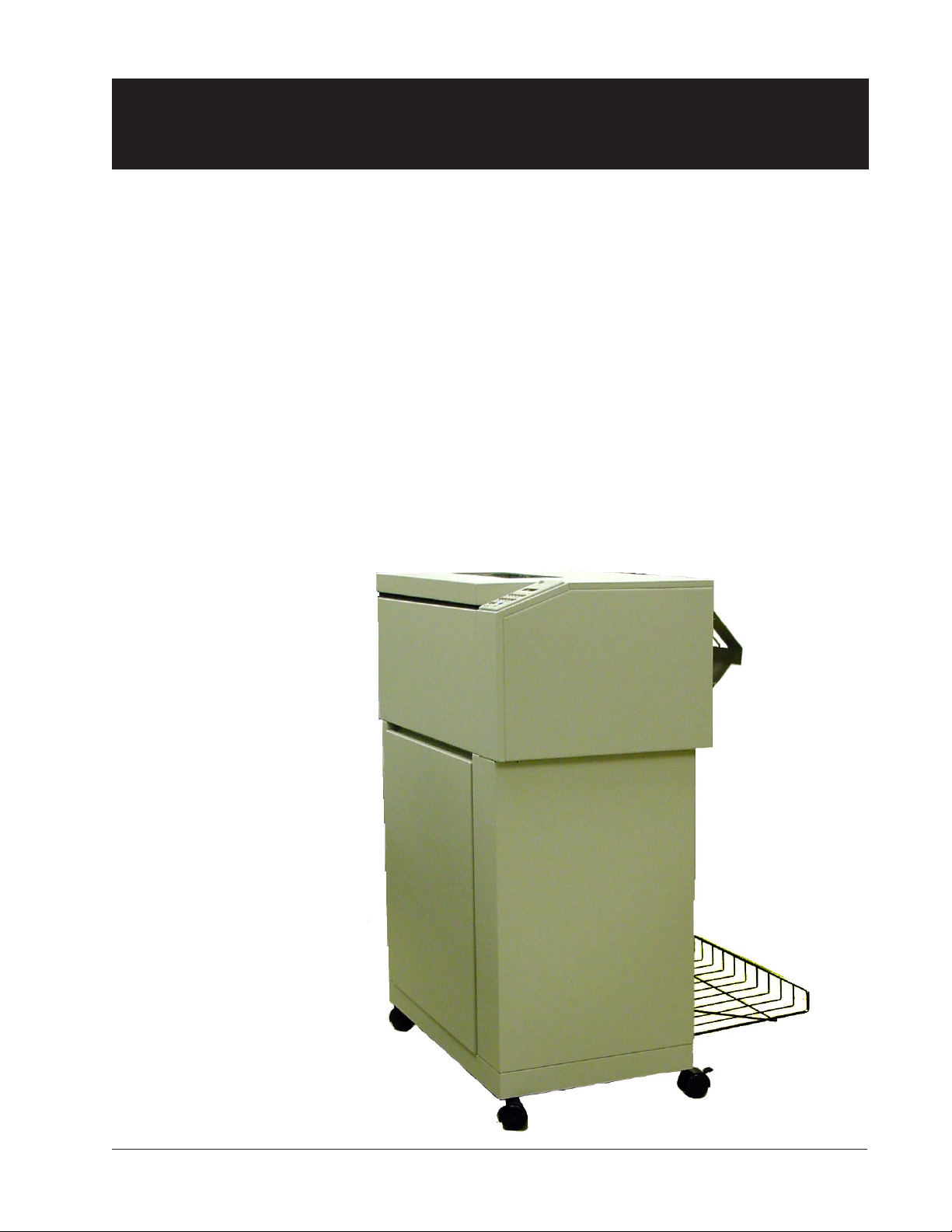
The 6300 Series Line Matrix Impact Printers are designed to handle heavy duty,
high volume workloads, with a straight paper path that provides unattended, jamfree printing of continuous forms, at high speeds. They have a wide range of
printer emulations, network printer management ability, popular graphics
languages and web administration utilities.
The 6300 Series offers the following I/O configurations (Modules):
• Standard Serial/Parallel
• FourPlex (Standard plus Twinax/Coax)
• FourPlex IPDS
• LANPlex (Standard plus Ethernet 10/100 BASE-T)
• LANPlex IPDS
In less than five minutes you can add other configurations by inserting a new
module. Installation instructions come with the module.
All interface configurations and printer setups
are performed through the control panel on the
top right of the unit. And since the printer’s
operational configuration is stored in nonvolatile
memory; you’ll never have to reconfigure your
printer because of a power loss.
Operator Manual Preface–11

About This Manual
Conventions
We use the following conventions throughout this manual:
Text that is placed in italics draws your attention to additional helpful
information.
Sometimes your attention is more particularly drawn by the use of this symbol.
CAREFUL!
This symbol marks information about actions
that may damage the equipment or injure the
user.
Preface–12 Operator Manual
Chapter 1
Site Preparation
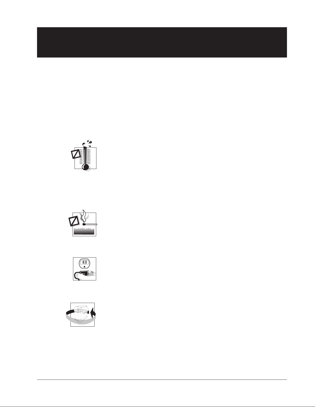
Choosing a site for your printer is important because the environment affects
your print quality. The best site for your printer is one that is protected from
dirt and heavy dust, and has a moderate temperature and humidity range. In
addition, the power source should be adequate for printer operation and
protected from power surges.
Keep the following factors in mind when choosing a printer location:
• Keep the operating environment temperature between 50°F and 104°F
• Do not locate your printer near air conditioners, open windows, heaters,
• The relative humidity should be between 10% and 90%
• The heat load contribution to the environment is 188 BTUs per hour at
(10°C and 40°C).
nor in other areas where the temperature changes abruptly.
(noncondensing). Be sure to locate the printer away from any sources of
moisture, such as water faucets, refrigerators, and humidifiers.
idle and can go as high as 2050 BTUs per hour under continuous fullload printing conditions.
• Keep your printer away from dust, dirt, and open flames.
• Plug your printer into a grounded outlet.
• Minimum floor space recommended for your printer is 36" wide x 36"
deep (91.4 cm x 91.4 cm) to allow air movement around the printer.
Allow space to open printer doors as well. When the doors are fully
opened, the printer takes up 6.5 feet (2.0 m) of floor space.
Chapter 1: Setting Up Your Printer 1–13
Unpacking the Printer
Unpacking your printer
Instructions for unpacking your printer are located on the outside of the shipping
container. After you have removed your printer from its container, store the
shipping materials for possible later use.
Repacking
Repacking your printer for storage or shipping is the reverse order of unpacking.
If shipping materials are needed, you can reorder them from your dealer.
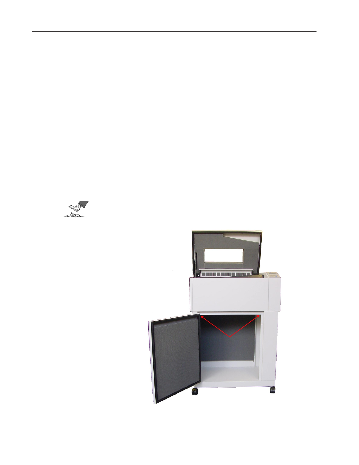
Removing the Shipping Hardware
The Shipping Hardware consists of 4 screws, identified by red tags, that secure the
printer base to the inside mechanism, and tie restraints that secure the Paper
Stacking Chains. The shipping screws fasten from underneath, 2 near the front of
the print cabinet and 2 near the rear of the cabinet.
CAREFUL!
DO NOT power up your printer before removing the shipping
hardware.
Arrows point to 4
shipping screw locations
1–14 Operator Manual
Figure 1 - 1. Shipping Screw Locations
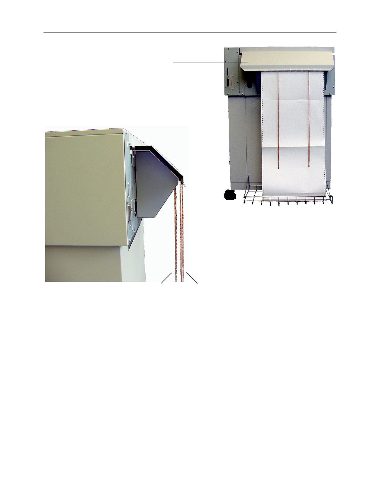
Rear Paper Guide
Paper Stacking Chains
Paper comes out between these
two sets of chains.
Figure 1 - 2. Paper Stacking Chains
Rear Guide Assembly Instructions
Use the two screws already installed in the back of the printer to secure the Rear
Guide Assembly (packed separately). Cut the plastic ties and remove the plastic
bag holding the paper chains. Paper exits the printer through these passive paper
stacking chains that help fold and stack printed forms uniformly. Make sure the
chains are not tangled.
Chapter 1: Setting Up Your Printer 1–15
Interface Connections
Interface Connections and Powering Up
Interface Connectors
Properly secure the cable to the printer interface using the correct connectors.
CAREFUL!
Connecting the I/O
Shielded I/O cables must be used on all installations to
comply with regulatory requirements.
After connecting each interface to your printer, run a print job from the Host
Computer to verify proper function of the printer.
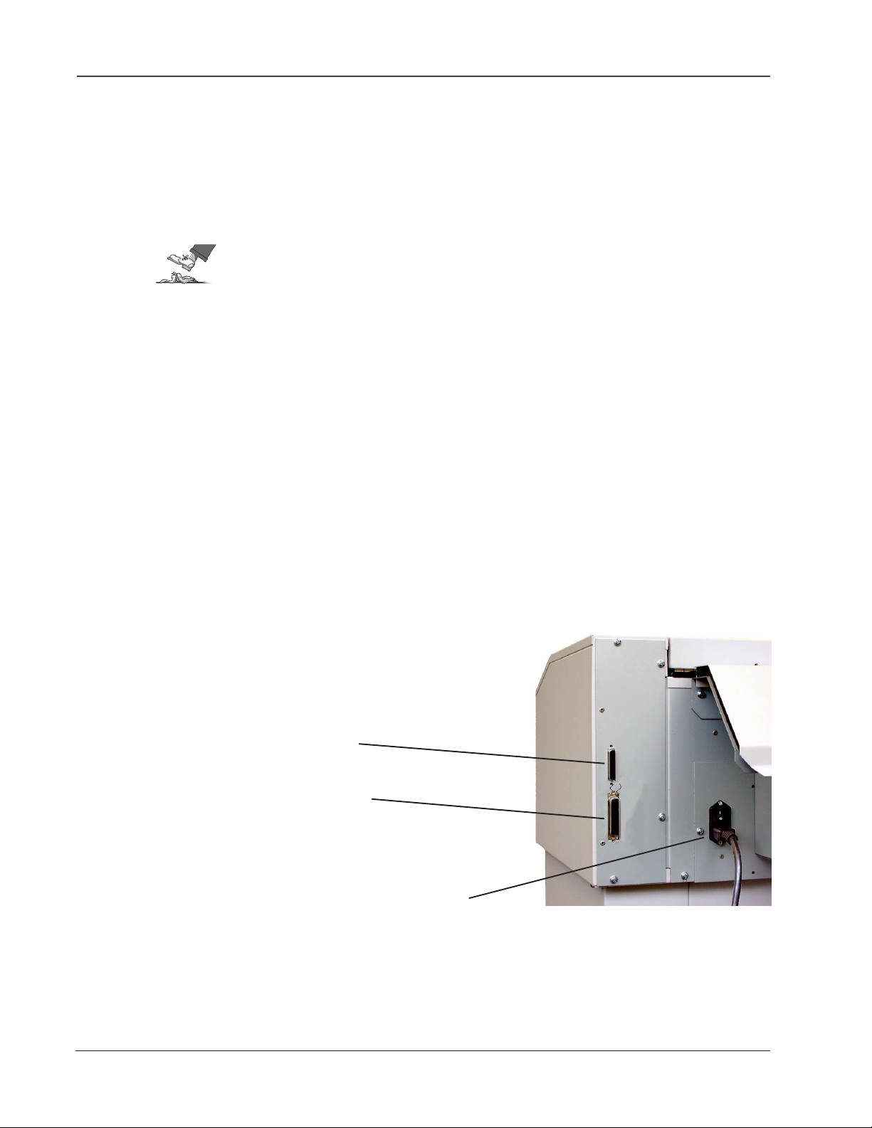
Serial/Parallel Interfaces
To connect the Serial or Parallel I/O cable, plug in the cable to the proper
connector on the I/O panel.
The serial interface operates up to 38.4 kBaud and uses a standard DB 25 serial
cable connector and standard RS-232-C signals. Serial interface cables should be
no longer than 50 feet (15.2 meters).
The Centronics parallel port is IEEE-1284 compliant and uses a 36-pin 1284-B
type connector (AMP 555119-1 or equivalent). Parallel interface cables should be
no longer than 6 feet (2 meters)
Serial Interface Port
Parallel Interface Port
The optional Twinax and Coax interface modules are installed between the
Serial/Parallel connectors and the power plug. Appendix B: Optional Interfaces
describes these.
1–16 Operator Manual
Power Plug
Figure 1 - 3. Rear view, showing Serial, Parallel and Power Plugs
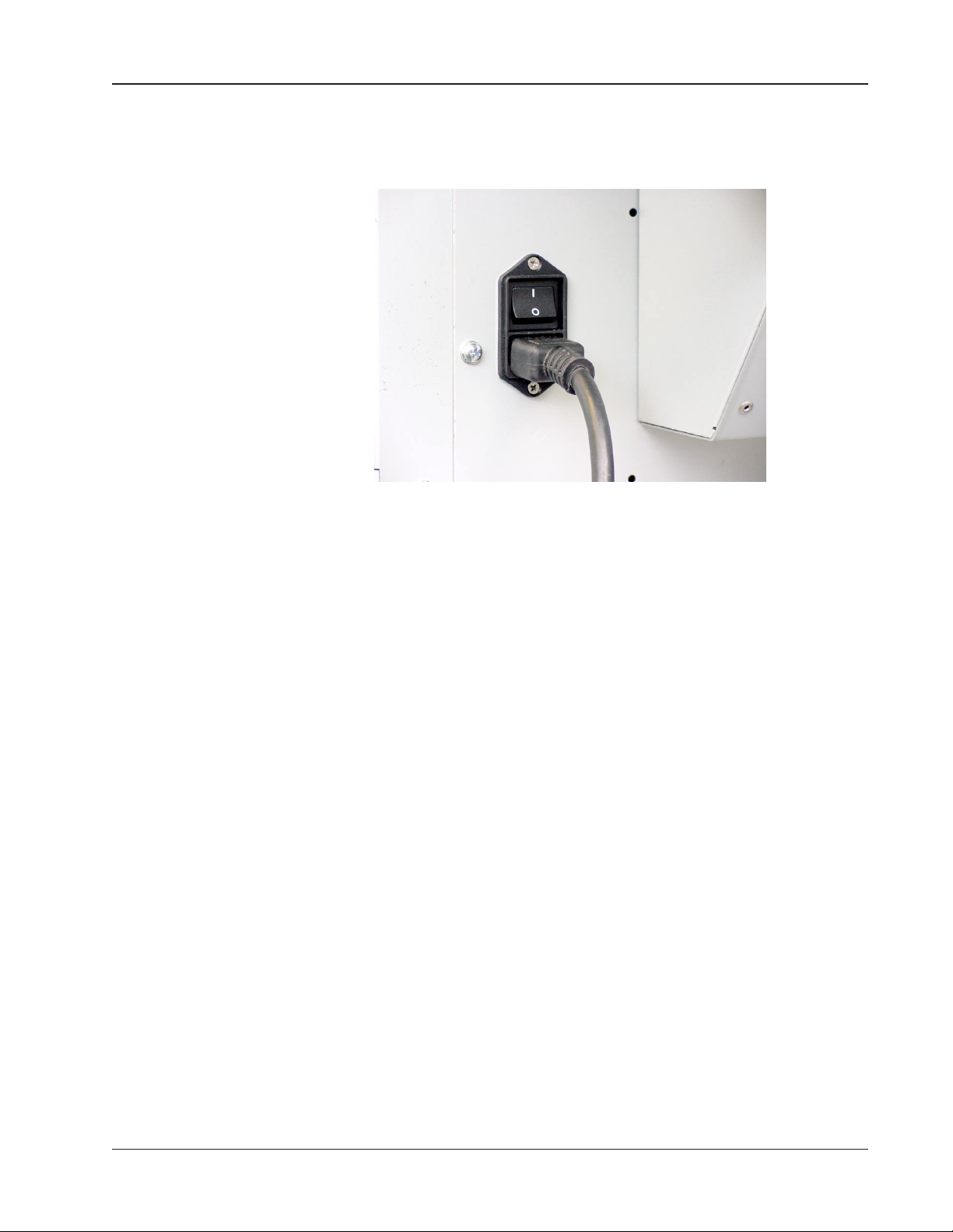
Powering Up
The power switch is located on the back of the printer, just above the 3-prong
power plug connector.
Powering Up
Figure 1 - 4. Power plug and on/off switch
Step 1.
Make sure the power is off by depressing the "0" side of the rocker power switch.
Connect the power cord. Plug the power cord into a proper power outlet.
Step 2.
Turn the power on.
The printer runs a self-test each time it is powered up to check the main
processor and buffers for errors. Note that when you turn the printer on this
time, the Paper Out error displays. If any error message appears in the display,
check Appendix A for a description of the error and what actions are necessary to
clear the error.
When connecting the Twinax interface at this time, other messages that may
appear are Setup Address and Lost Sync (28). These messages appear because
the printer/host interface has not been properly set up. If you cannot connect
the interface at this time, you can still test certain aspects of printer performance
by placing the printer Offline (depress the Online/Offline key), then entering the
Menu Mode. While in Menu Mode you may select print and operation
parameters or test certain printer systems.
Chapter 1: Setting Up Your Printer 1–17
Paper System Components
Paper System
Paper System Components
The Tractors, Ribbon Cartridge, Platen and Paper Iron are all parts of the paper
system. The first two can be seen when the lid is raised. The Platen and Paper
Iron are hidden inside the housing.
Tractors
Ribbon
support
platform
shaft for
tractors
Ribbon Cartridge
Figure 1 - 5. Inside the Lid
1–18 Operator Manual
Tractors
Tractors
Open
Paper System Components
The 6300 Series has two tractors to control paper movement, located on the left
and right.
A lever on each tractor keeps it locked in place on a horizontal shaft. To reposition a tractor, unlock the tractor and move it to the left or the right along the
shaft. Repositioning is generally needed only when inserting a new form or size of
paper.
Print Gap
locking
lever
Figure 1 - 6. Left and Right Paper Tractors
The 6300 Series line printers offer Auto-Gap which simplifies operator set-up and
printer use by setting the optimum print gap based on the form thickness. The
print gap is automatically opened to its widest position when the printer is not
printing. To accommodate various thicknesses of paper, the print gap is adjusted
either automatically or manually. (See Chapter 2 pages 2-30 to 2-33 and Chapter 3
pages 3-56 to 3-58). If the Print Gap Detect Mode has been set to "Auto," the auto
gap sensing operation will take place the first time the power is turned on,
immediately after a "paper out" fault, when the TOF key is pressed, and when
printing is attempted without setting the Top Of Form. Dedicated control panel
keys also allow the print gap to be adjusted based on operator preference.
Paper Tension
Vertical tension on the paper is pre-set. It is not controlled by the user.
Chapter 1: Setting Up Your Printer 1–19
Installing Ribbon Cartridge
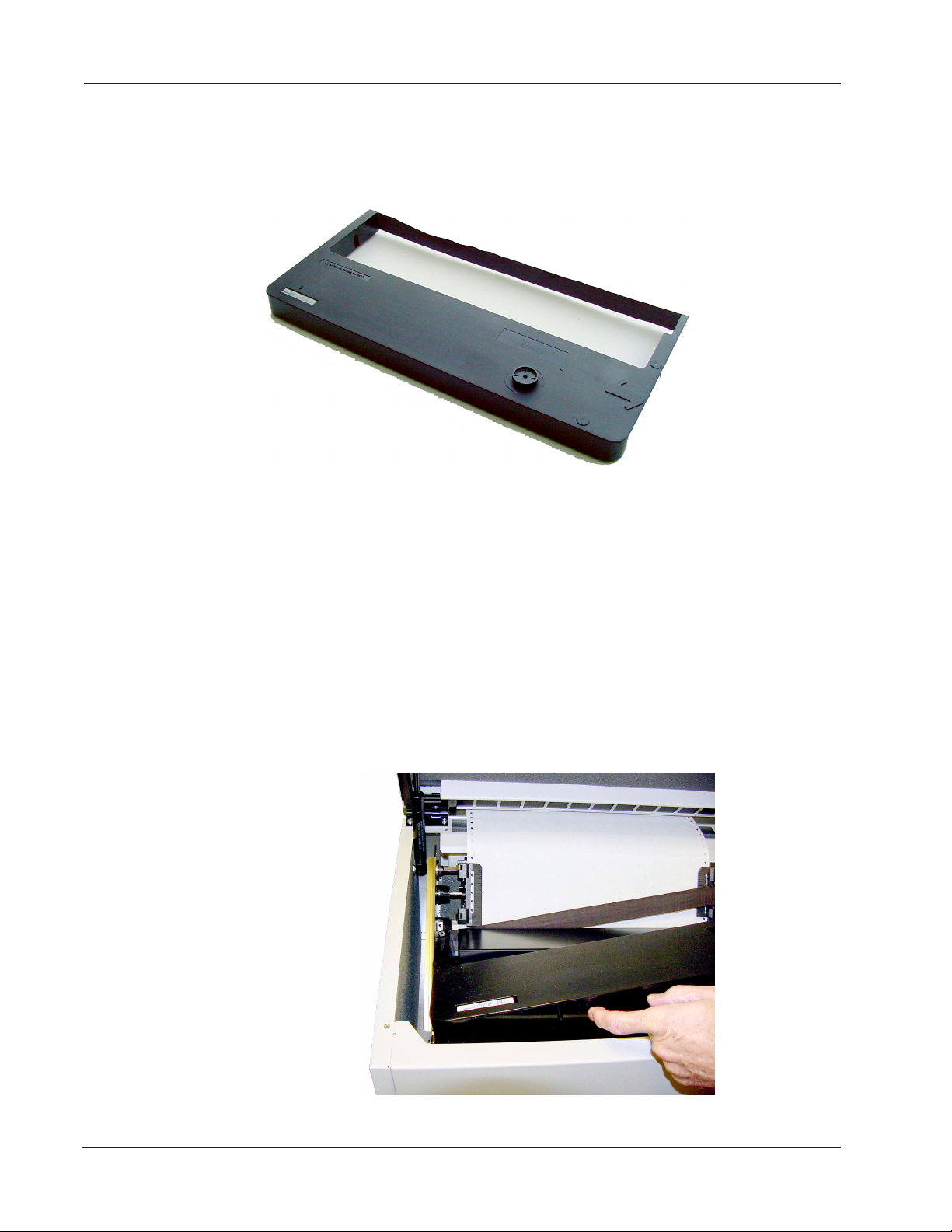
Installing the Ribbon Cartridge
Step 1.
Make sure the printer is Offline or power is off. Open the printer lid and remove
the old ribbon by lifting it straight up off of the Ribbon Platform.
Figure 1 - 7. Ribbon Cartridge
Step 2.
Remove slack in the new ribbon by turning the knob on the ribbon cartridge as
indicated by the arrow printed next to the knob, then slip the ribbon, left side
first, over the two ribbon guides and between the front and rear panels of the
ribbon shield on the printer.
Step 3.
Press down lightly on the cartridge while turning the ribbon knob as before until
it seats on first the left, (as shown), and then the right cartridge drive posts. Make
sure that the ribbon does not twist or fold over.
1–20 Operator Manual
Figure 1 - 8. Installing the Ribbon Cartridge
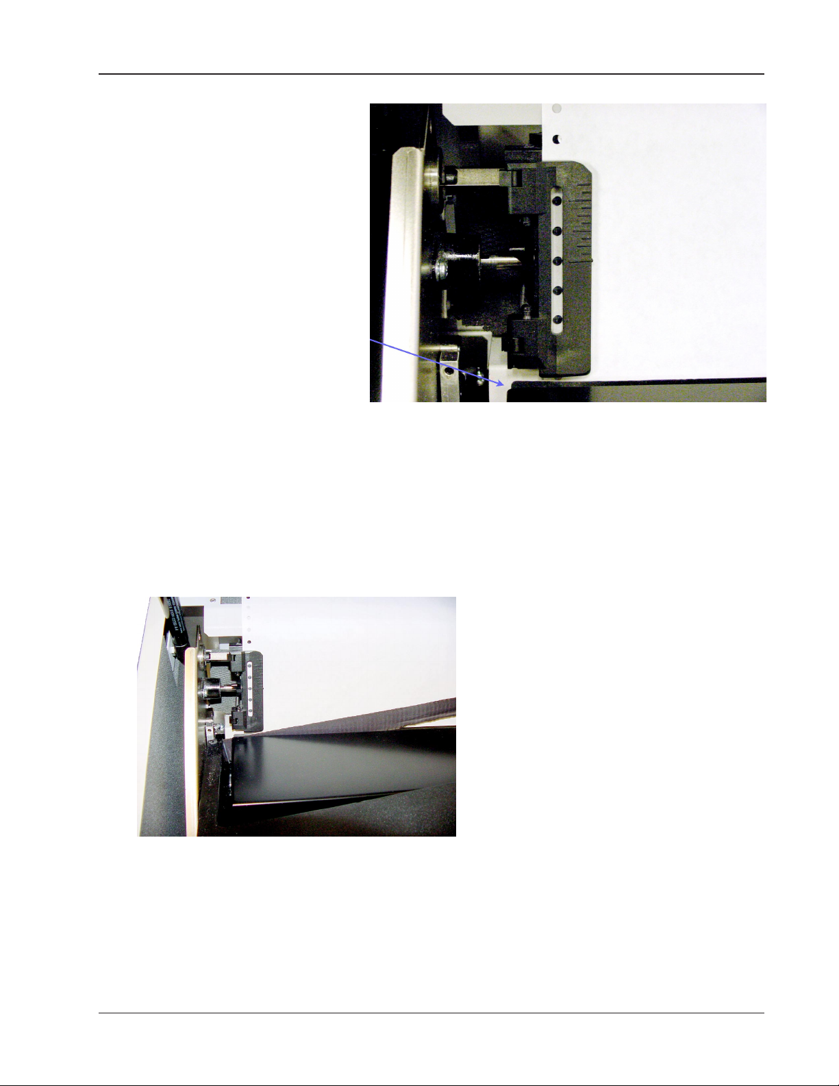
The front and rear
panels of the ribbon
shield
Installing Ribbon Cartridge
Figure 1 - 9. Ribbon Shield Panels
The ribbon has been carefully positioned
between the two panels of the ribbon shield.
Chapter 1: Setting Up Your Printer 1–21
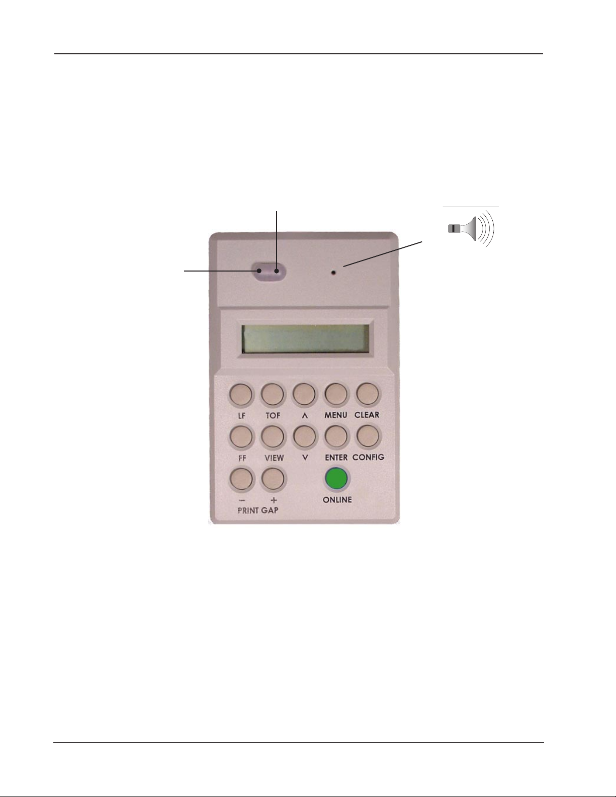
Control Panel Components
Control Panel Components
The Control Panel is located on the right front top of the printer housing. It is
used to program and direct most printer functions.
Red LED Indicator
Green LED Indicator
beeper
32-character
2-line LCD
}
display
LED Indicators
The green ONLINE indicator illuminates whenever there is power to the printer,
and the printer is Online.
The red FAULT Indicator illuminates whenever an error or fault is detected. A
message also appears on the display to indicate what kind of fault is present (see
Appendix A for explanations of all error and fault messages).
LCD (Liquid Crystal Display)
The 32-character, 2-line Liquid Crystal Display shows printer status, menu selections, normal, fault and error messages. It is divided into four main areas. The
displayed information will vary with menu selection and the configuration of the
printer.
1–22 Operator Manual
Figure 1 - 10. Control Panel

Once the printer has been unpacked, the cables connected, the ribbon cartridge
installed, and a box of paper (whether plain paper or pre-printed forms) placed
nearby, you are ready to load the paper and set the various parameters via the
Control Panel that will ensure that the 6300 Series printer performs exactly as you
need. This is covered in the next chapter.
Chapter 1: Setting Up Your Printer 1–23

Blank
Page
1–24 Operator Manual
Chapter 2
Introduction
This chapter covers how to load the paper and to set the print gap. It also covers
how to create saveable configuration settings for your own pre-printed forms.
Your printer is designed to use a continuous sheet, sprocket-fed paper. It can
handle:
• Six-part forms (1 original and 5 copies) with a maximum thickness of
• Page widths of 2.5" to 18" (6.4 cm to 45.7 cm).
Specific requirements for pre-printed forms are in Appendix C: Specifications.
.025" (0.6 mm).
Chapter 2: Loading Paper and Printing 2–25
Standard Printing Mode
Loading Paper for Standard Printing Mode
Step 1.
Turn off the printer using the power switch on the back, or toggle the "Online"
button on the Control Panel until the LCD shows "Offline".
Step 2.
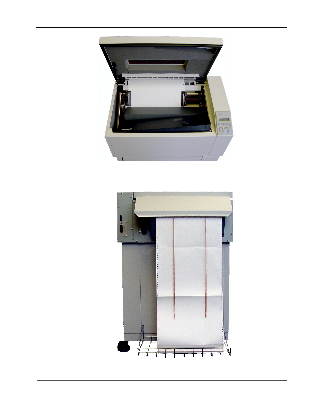
Raise the printer lid and open the doors on both tractors.
Figure 2 - 1. Inside Paper Inlet, visible when looking inside the printer cabinet.
Step 3.
Open the new box of paper. Remove the box top so that the paper can be
pulled out freely. Open the front of the printer cabinet and place the new box of
paper inside.
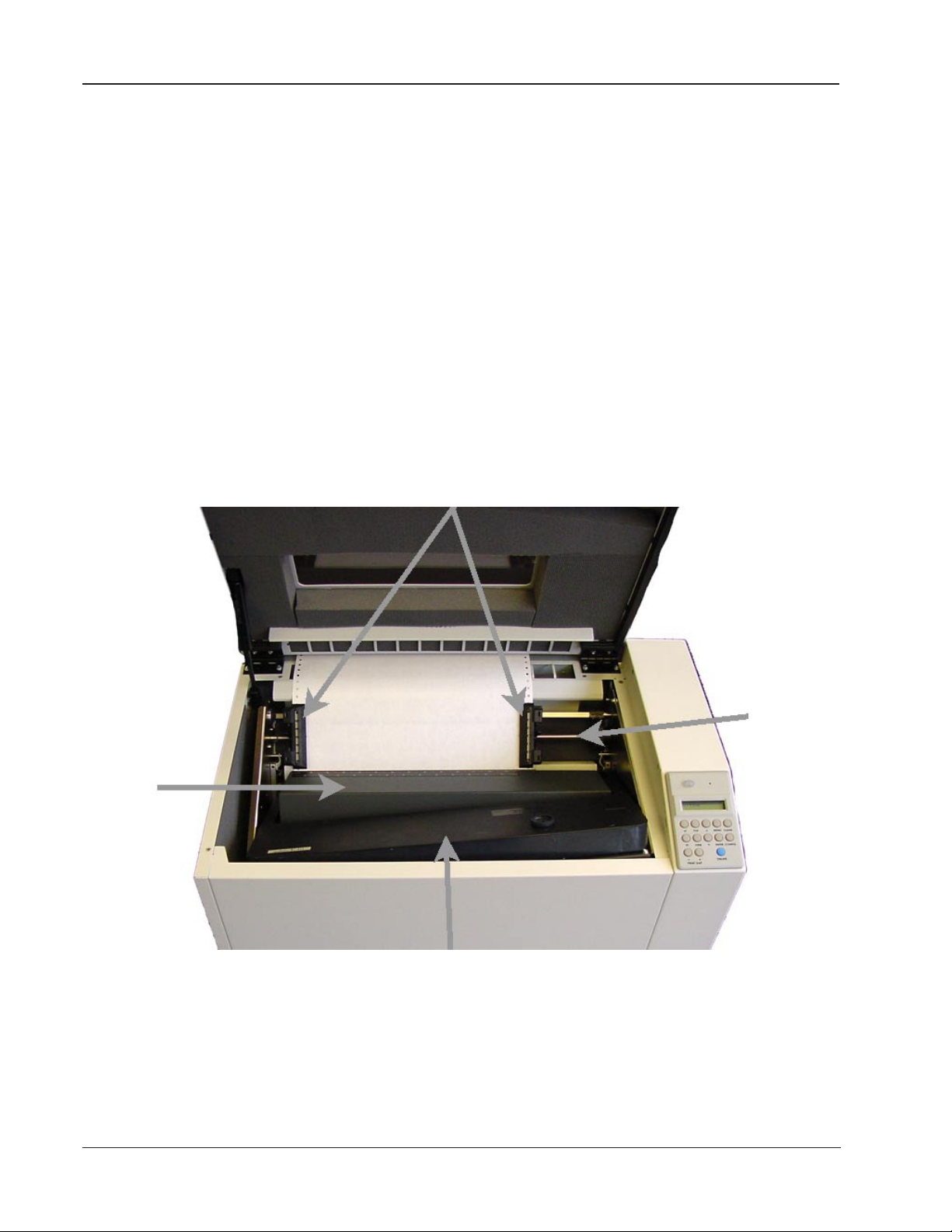
Step 4.
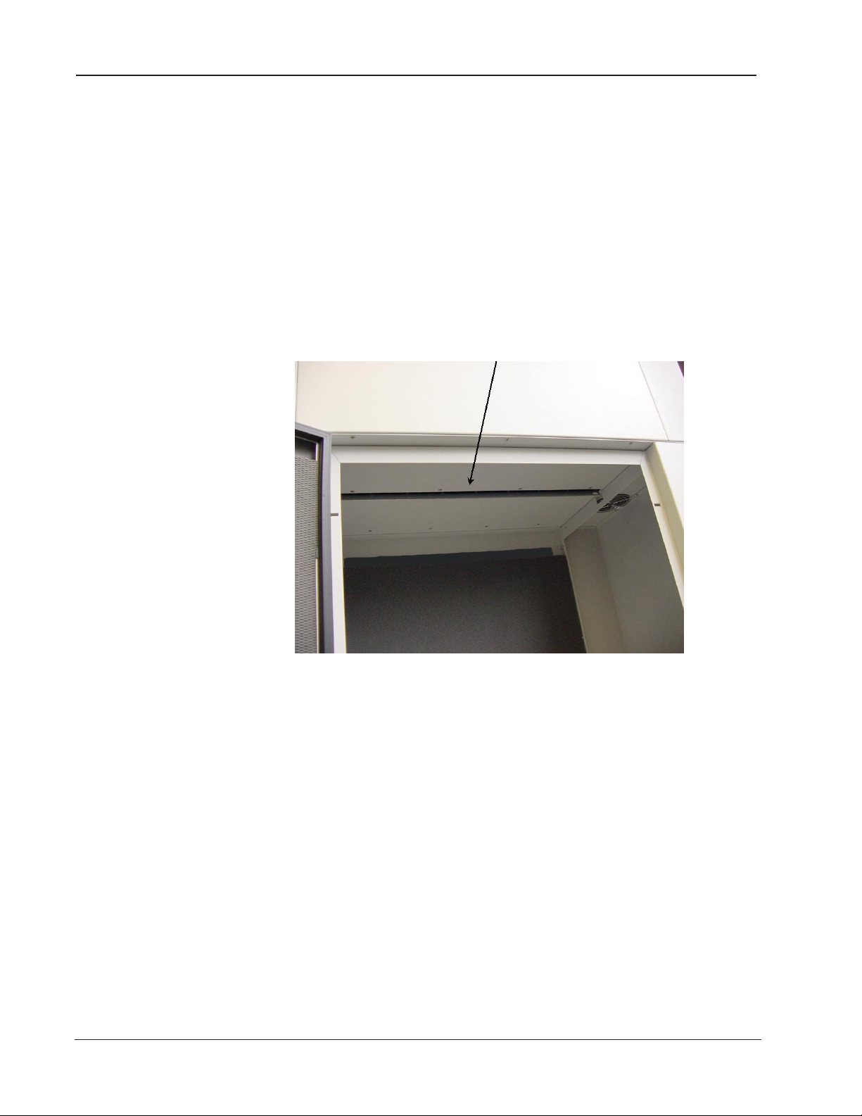
Feed the paper up through the paper inlet, as shown in figure 2-1, a little ways
past the tractors and through the gap between the top back of the printer and
the lid (Figure 2-2). It will flow out between the paper chains and fold into the
wire rack near the floor (Figure 2-3).
Step 5.
Place the left-side paper holes onto the left tractor pins and close the tractor
door.
2–26 Operator Manual
Feed paper
between the
lid and the
top of the
printer.
Standard Printing Mode
Figure 2 - 2. Paper path past the lid.
Figure 2 - 3. Paper path into the wire rack.
Chapter 2: Loading Paper and Printing 2–27
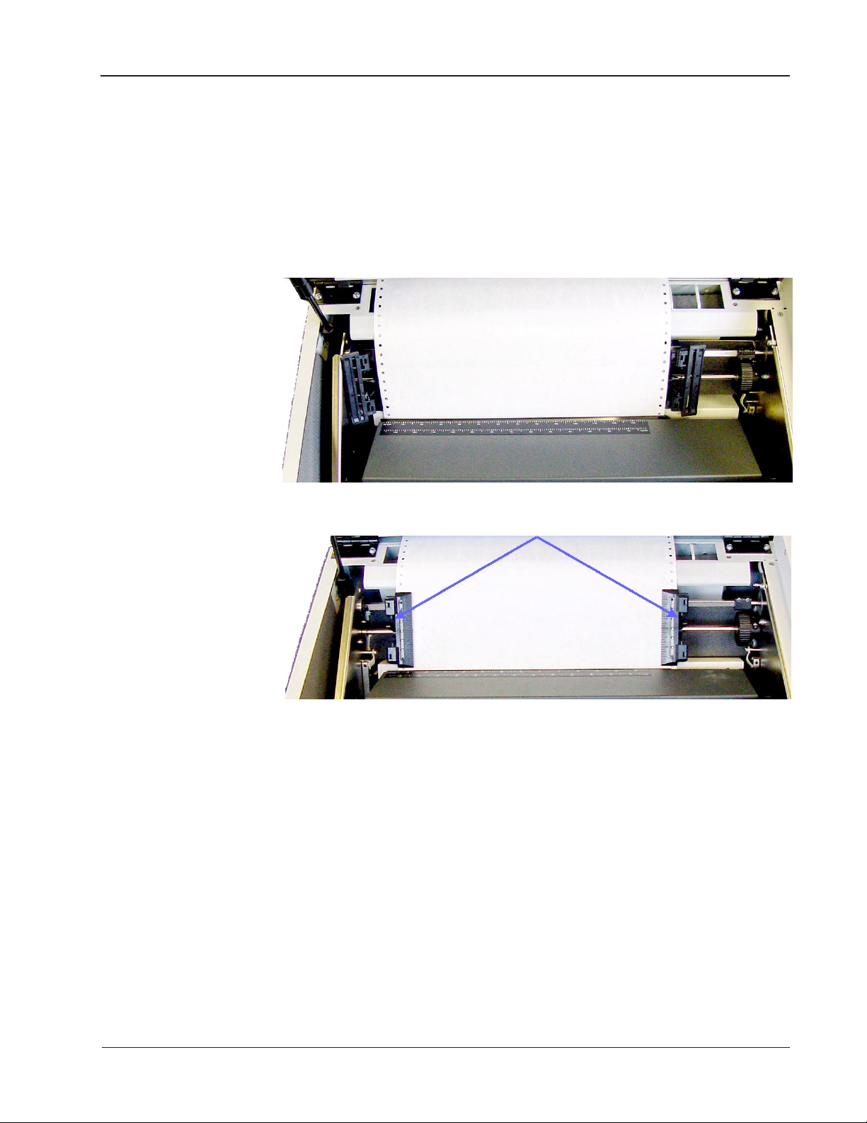
Standard Printing Mode
Step 6.
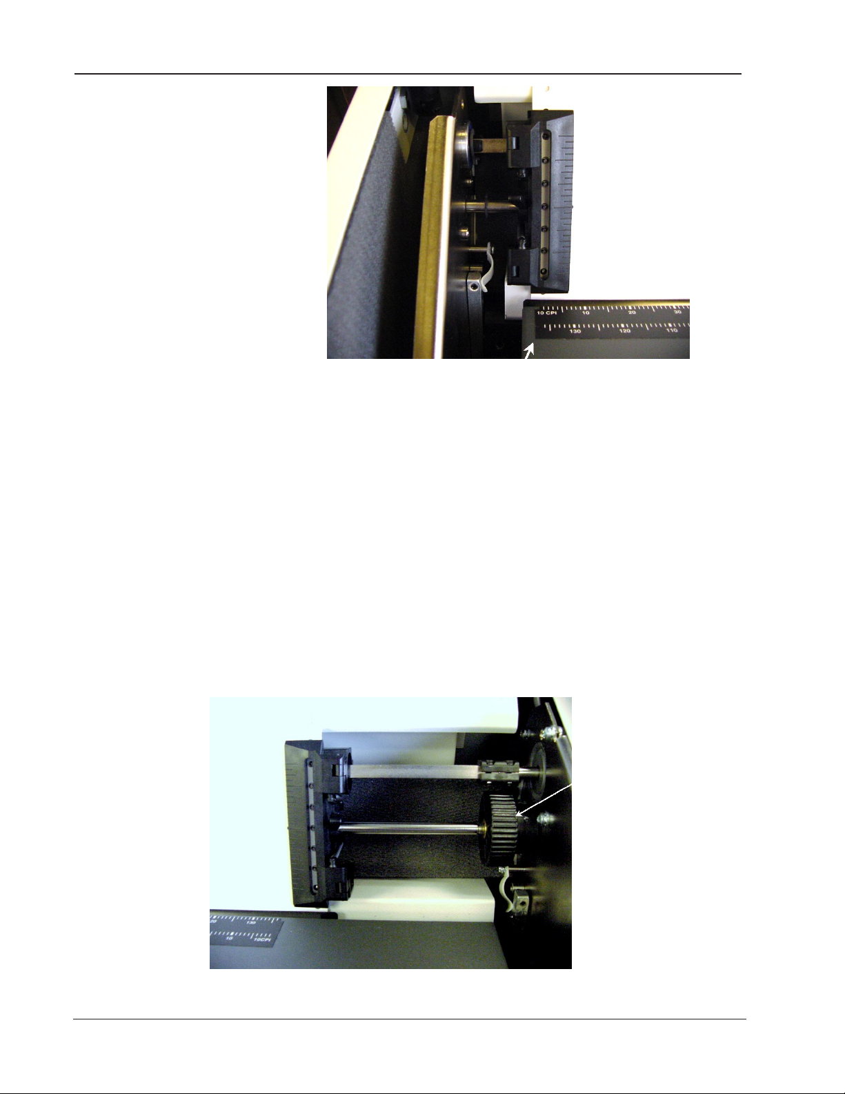
The Column Alignment Scale is on the top of the ribbon support platform. It is
to be used for general guidance in horizontally aligning the form for each print
job. The leftmost mark on the scale indicates the location of the first, or leftmost,
printable character. Each successive tick mark indicates the location of additional
10 CPI characters.
Figure 2 - 4. Column Alignment Scale
Unlock the right tractor and move it so that the paper's holes align directly over
the tractor pins, making sure that the paper is straight, then close the tractor
door. Gently push the tractor to the right until the paper is smooth. Unlock the
left tractor and, keeping the paper reasonably taut, holding onto both tractors,
move the paper to the left or the right until it is roughly aligned with the desired
mark on the Column Alignment Scale. Lock both tractors.
Horizontal Vernier Wheel
2–28 Operator Manual
Figure 2 - 5. Horizontal Vernier Wheel
Step 7.
Standard Printing Mode
Fine-tuning the Column Alignment can be done in two ways:
(1) Rotate the Horizontal Vernier Wheel, which is located on the right end of the
shaft on which the tractors ride. Depending upon the direction the paper needs to
move, you will rotate the wheel either upwards or downwards.
(2) Use the Control Panel. Go Offline, choose Menu, then use the arrow keys to
get to the Operator Menu. Press Enter. Use the arrow keys to get to Forms. Press
Enter. Use the arrow keys to get to Horz Adjust. Press Enter. Use the arrow keys
to increase or decrease the number that appears in the lower right of the LCD.
This will shift the position of Column 1.
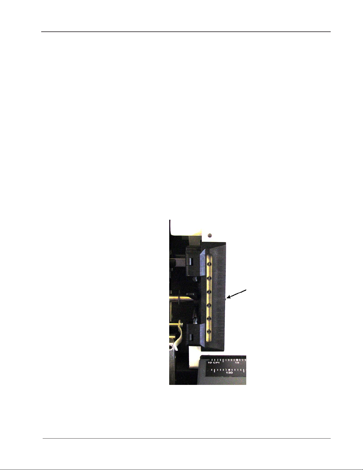
Set the Top of the Form (TOF). This is done from the Control Panel. If the
printer is not on, turn it on now. If necessary, press the Online key until “Offline”
is displayed. Use the up or down arrow keys to move the perforation line on the
paper so that it is aligned with the nubbin on the tractor door. Once the paper is
positioned, press the TOF key. The paper will move downward to the “ready to
print” position and the correct print gap will be set based on the form thickness.
Nubbin
- - - - - - - - - - - - - - - - - - - - - - - - - - - - - -
Figure 2 - 6. Top of Form Nubbin
Chapter 2: Loading Paper and Printing 2–29

Print Gap
Print Gap Adjustment
The 6300 Series Auto-Gap feature automatically sets the correct print gap based
on form thickness. Dedicated control panel keys also allow the print gap to be
adjusted for darker or lighter print based on user preference. For ease of paper
loading, the print gap is set to its widest position while the printer is not printing.
The Auto-Gap feature is automatically initiated under the following conditions:
1. The Print Gap Mode is Auto, the printer has been off but is now turned on,
and a TOF is set before any printing has begun.
2. The Print Gap Mode is Auto, the printer has been off but is now turned on,
and a print run is started before TOF is set.
3. The Print Gap Mode is Auto, a Paper Out Fault has been cleared, and either
the TOF is set or a print run is resumed.
4. The Print Gap Mode is Auto, the printer has been off but is now turned on,
and an adjustment is made using the “-” or “+” Print Gap keys on the Control
Panel.
Even though the print gap value has been automatically determined, there might
be times when it needs to be further fine-tuned using the Control Panel as described below under Manually Adjust Print Gap on Control Panel.
Gap Zone
The Gap Zone feature is used to set up a variable print gap for forms that contain
areas of varying thickness. This is done by creating a Gap Zone Profile for the
form, saving it in one of the ten saved configurations, then loading that configuration whenever the particular form is used.
Print Gap Profile Mode
As previously described, the Print Gap Mode is set up in the Print Gap Category of
the Operator Menu. There are three Print Gap Modes. In Manual Mode, the print
gap is set manually using the Print Gap keys on the control panel. In Auto Mode
(default), the print gap is automatically detected whenever a new form is loaded,
and when the printer is powered on. Profile Mode is the mode that must be set
when using the Gap Zone feature, as described below.
Creating a Gap Zone Profile
A Gap Zone Profile is created automatically in four simple steps:
Step 1 – Load the Form
Load the form for which the profile will be generated. Be sure to set the Top
of Form position, and be sure that the Form Length is set properly.
Step 2 – Set Profile Mode
The Print Gap Mode is set up in the Print Gap Category of the Operator Menu. Set
the Mode Parameter to Profile. Press Operator Menu => PrintGap => Mode =>
Profile => Enter.
2–30 Operator Manual
 Loading...