

Page 1

6000 Series
Applications Manual
Volume 6
MTPL Command Reference
Page 2

Table of Contents
Description of MTPL-Sequences
Introduction . . . . . . . . . . . . . . . . . . . . . . . . . . . . . . . . . . . 2
Paper and Text Formatting . . . . . . . . . . . . . . . . . . . . . . . . . . 5
Form Length . . . . . . . . . . . . . . . . . . . . . . . . . . . . . . . . 5
Turn ON Positioning Unit Mode (SM) . . . . . . . . . . . . . . . . . . . 7
Turn OFF Positioning Unit Mode (RM) . . . . . . . . . . . . . . . . . . 7
Select Size Unit (SSU) . . . . . . . . . . . . . . . . . . . . . . . . . . 8
Set Top and Bottom Margin . . . . . . . . . . . . . . . . . . . . . . . . 9
Clear Top and Bottom Margin . . . . . . . . . . . . . . . . . . . . . . . 9
Set Left and Right Margin . . . . . . . . . . . . . . . . . . . . . . . . . 11
Clear Left and Right Margin . . . . . . . . . . . . . . . . . . . . . . . . 11
Set Line Home (SLH) . . . . . . . . . . . . . . . . . . . . . . . . . . . 13
Set Line Limit (SLL) . . . . . . . . . . . . . . . . . . . . . . . . . . . . 13
Right Justification ON . . . . . . . . . . . . . . . . . . . . . . . . . . . 14
Centering ON . . . . . . . . . . . . . . . . . . . . . . . . . . . . . . . 14
Right Justification and Centering OFF . . . . . . . . . . . . . . . . . . . 14
Character Spacing . . . . . . . . . . . . . . . . . . . . . . . . . . . . . . . 15
Spacing Increment (SPI) . . . . . . . . . . . . . . . . . . . . . . . . . 15
Horizontal Spacing . . . . . . . . . . . . . . . . . . . . . . . . . . . . 16
Horizontal Character Spacing (SHS) . . . . . . . . . . . . . . . . . . . 18
Character Spacing (SCS) . . . . . . . . . . . . . . . . . . . . . . . . . 19
Additional Character Spacing (SACS) . . . . . . . . . . . . . . . . . . . 20
Reduced Character Spacing (SRCS) . . . . . . . . . . . . . . . . . . . 21
Horizontal Motion Index (HMI) . . . . . . . . . . . . . . . . . . . . . . . 22
Horizontal Step (Microspace) . . . . . . . . . . . . . . . . . . . . . . . 23
Page 3

Line Spacing . . . . . . . . . . . . . . . . . . . . . . . . . . . . . . . . . . 24
Vertical Spacing (SVS) . . . . . . . . . . . . . . . . . . . . . . . . . . 24
Line Density 6 lpi . . . . . . . . . . . . . . . . . . . . . . . . . . . . . 25
Line Density 8 lpi . . . . . . . . . . . . . . . . . . . . . . . . . . . . . 25
Set Line Spacing (SLS) . . . . . . . . . . . . . . . . . . . . . . . . . . 26
Character Styling . . . . . . . . . . . . . . . . . . . . . . . . . . . . . . . . 27
Superscript ON . . . . . . . . . . . . . . . . . . . . . . . . . . . . . . 27
Subscript ON . . . . . . . . . . . . . . . . . . . . . . . . . . . . . . . 27
Microscript ON . . . . . . . . . . . . . . . . . . . . . . . . . . . . . . . 27
Super-/Sub-/Microscript OFF . . . . . . . . . . . . . . . . . . . . . . . 27
Double Height ON (Upper Half) . . . . . . . . . . . . . . . . . . . . . . 29
Double Height ON (Lower Half) . . . . . . . . . . . . . . . . . . . . . . 29
Double Height OFF . . . . . . . . . . . . . . . . . . . . . . . . . . . . 29
Print Quality . . . . . . . . . . . . . . . . . . . . . . . . . . . . . . . . 31
Select Typestyle . . . . . . . . . . . . . . . . . . . . . . . . . . . . . . 33
Emphasized Mode ON . . . . . . . . . . . . . . . . . . . . . . . . . . 35
Emphasized Mode OFF . . . . . . . . . . . . . . . . . . . . . . . . . . 35
Italic Mode ON . . . . . . . . . . . . . . . . . . . . . . . . . . . . . . 36
Italic Mode OFF . . . . . . . . . . . . . . . . . . . . . . . . . . . . . . 36
Proportional Mode ON (SGR) . . . . . . . . . . . . . . . . . . . . . . . 37
Proportional Mode OFF . . . . . . . . . . . . . . . . . . . . . . . . . 37
Underline Mode ON (SGR) . . . . . . . . . . . . . . . . . . . . . . . . 39
Underline Double Mode . . . . . . . . . . . . . . . . . . . . . . . . . . 39
Underline Mode OFF . . . . . . . . . . . . . . . . . . . . . . . . . . . 39
Overline Mode ON (SGR) . . . . . . . . . . . . . . . . . . . . . . . . . 40
Overline Mode OFF . . . . . . . . . . . . . . . . . . . . . . . . . . . . 40
Double Strike ON . . . . . . . . . . . . . . . . . . . . . . . . . . . . . 41
Double Strike OFF . . . . . . . . . . . . . . . . . . . . . . . . . . . . . 41
Graphic Size Selection (GSS) . . . . . . . . . . . . . . . . . . . . . . . 42
Graphic Size Modification (GSM) . . . . . . . . . . . . . . . . . . . . . 42
Font Designation (FNT) . . . . . . . . . . . . . . . . . . . . . . . . . . 43
Print Positioning . . . . . . . . . . . . . . . . . . . . . . . . . . . . . . . . 45
Page 4

Horizontal Tab Stop . . . . . . . . . . . . . . . . . . . . . . . . . . . . 45
Set Horizontal Tab Stop at Current Position . . . . . . . . . . . . . . . . 45
Horizontal Tab Stops ON . . . . . . . . . . . . . . . . . . . . . . . . . 46
Horizontal Tab Stops OFF (TBC) . . . . . . . . . . . . . . . . . . . . . 46
Line Feed . . . . . . . . . . . . . . . . . . . . . . . . . . . . . . . . . 49
Vertical Tab Stop . . . . . . . . . . . . . . . . . . . . . . . . . . . . . 50
Set Vertical Tab Stop at Current Position . . . . . . . . . . . . . . . . . 51
Vertical Index . . . . . . . . . . . . . . . . . . . . . . . . . . . . . . . 51
Vertical Tab Stops ON . . . . . . . . . . . . . . . . . . . . . . . . . . . 52
Vertical Tab Stops OFF (TBC) . . . . . . . . . . . . . . . . . . . . . . 52
Horizontal Posititon Absolute (HPA) . . . . . . . . . . . . . . . . . . . 54
Horizontal Position Relative (HPR) . . . . . . . . . . . . . . . . . . . . 55
Horizontal Position Backward (HPB) . . . . . . . . . . . . . . . . . . . 56
Vertical Position Absolute (VPA) . . . . . . . . . . . . . . . . . . . . . 57
Vertical Position Relative (VPR) . . . . . . . . . . . . . . . . . . . . . 58
Vertical Position Backward (VPB) . . . . . . . . . . . . . . . . . . . . . 59
Horizontal and Vertical Position Absolute (HVP) . . . . . . . . . . . . . 60
Backspace . . . . . . . . . . . . . . . . . . . . . . . . . . . . . . . . 61
Carriage Return . . . . . . . . . . . . . . . . . . . . . . . . . . . . . . 61
Form Feed . . . . . . . . . . . . . . . . . . . . . . . . . . . . . . . . 62
Partial Line Down . . . . . . . . . . . . . . . . . . . . . . . . . . . . . 63
Partial Line Up . . . . . . . . . . . . . . . . . . . . . . . . . . . . . . . 63
Reverse Index . . . . . . . . . . . . . . . . . . . . . . . . . . . . . . . 64
Next Line . . . . . . . . . . . . . . . . . . . . . . . . . . . . . . . . . 64
Graphics . . . . . . . . . . . . . . . . . . . . . . . . . . . . . . . . . . . . 65
Graphic Modes . . . . . . . . . . . . . . . . . . . . . . . . . . . . . . 65
Miscellaneous . . . . . . . . . . . . . . . . . . . . . . . . . . . . . . . . . 69
Load Menu . . . . . . . . . . . . . . . . . . . . . . . . . . . . . . . . . 69
Automatic Gap Adjustment (AGA) . . . . . . . . . . . . . . . . . . . . . 70
Direct Setting of the Print Head Distance . . . . . . . . . . . . . . . . . 70
Paper Handling . . . . . . . . . . . . . . . . . . . . . . . . . . . . . . 71
Shared Interface . . . . . . . . . . . . . . . . . . . . . . . . . . . . . 71
Page 5

Color Selection (Option) . . . . . . . . . . . . . . . . . . . . . . . . . . 72
Input Data Control . . . . . . . . . . . . . . . . . . . . . . . . . . . . . 74
Sheet Feeder/Paperway . . . . . . . . . . . . . . . . . . . . . . . . . 76
Eject Form . . . . . . . . . . . . . . . . . . . . . . . . . . . . . . . . . 76
Reset to Initial State (RIS) . . . . . . . . . . . . . . . . . . . . . . . . . 79
Command Set . . . . . . . . . . . . . . . . . . . . . . . . . . . . . . . 80
Activation of Character Sets . . . . . . . . . . . . . . . . . . . . . . . 81
Designation of Character Set G0 . . . . . . . . . . . . . . . . . . . . . 83
Designation of Character Set G1 . . . . . . . . . . . . . . . . . . . . . 83
Designation of Character Set G2 . . . . . . . . . . . . . . . . . . . . . 83
Designation of Character Set G3 . . . . . . . . . . . . . . . . . . . . . 83
Activation of Characters . . . . . . . . . . . . . . . . . . . . . . . . . . 86
Size of Character Set (1 Character Set) . . . . . . . . . . . . . . . . 88
Size of Character Set (2 Character Sets) . . . . . . . . . . . . . . . . . 88
Proportional Spacing (Draft) OFF . . . . . . . . . . . . . . . . . . . . 89
Proportional Spacing (Draft) ON . . . . . . . . . . . . . . . . . . . . . . 89
Font Selection for NLQ/LQ only . . . . . . . . . . . . . . . . . . . . . . 89
Font Selection . . . . . . . . . . . . . . . . . . . . . . . . . . . . . . . 89
Print Code Area Expansion ON . . . . . . . . . . . . . . . . . . . . . . 90
Print Code Area Expansion OFF . . . . . . . . . . . . . . . . . . . . 90
Print Transparent Characters . . . . . . . . . . . . . . . . . . . . . . . 90
Printer Identification (DA) . . . . . . . . . . . . . . . . . . . . . . . . . 91
Device Status Report (DSR) . . . . . . . . . . . . . . . . . . . . . . . . 92
Enquiry for Status . . . . . . . . . . . . . . . . . . . . . . . . . . . . . 93
Fill Character . . . . . . . . . . . . . . . . . . . . . . . . . . . . . . . 94
Start of Text Block . . . . . . . . . . . . . . . . . . . . . . . . . . . . . 94
End of Text Block . . . . . . . . . . . . . . . . . . . . . . . . . . . . . 95
Positive Acknowledge . . . . . . . . . . . . . . . . . . . . . . . . . . . 95
Negative Acknowledge . . . . . . . . . . . . . . . . . . . . . . . . . . 96
Clear Print Buffer . . . . . . . . . . . . . . . . . . . . . . . . . . . . . 96
Delete . . . . . . . . . . . . . . . . . . . . . . . . . . . . . . . . . . . 97
Acoustic Alarm . . . . . . . . . . . . . . . . . . . . . . . . . . . . . . . 97
Start Character “Escape” . . . . . . . . . . . . . . . . . . . . . . . . . 98
MTPL-Start Character “Control Sequence Introducer” . . . . . . . . . . 98
Page 6

Appendix A Summary of Possible Codes
Sorted by Sequences . . . . . . . . . . . . . . . . . . . . . . . . . . . . . A-2
Sorted by Functions . . . . . . . . . . . . . . . . . . . . . . . . . . . . . A-8
Appendix B Character Sets
Standard Character Set . . . . . . . . . . . . . . . . . . . . . . . . . . . . B-2
International Substitution Table – normal font . . . . . . . . . . . . . . . B-3
Appendix C Additional Technical Description
Index
Page 7

Description of MTPL-Sequences
Introduction
Paper and Text Formatting
Character Spacing
Line Spacing
Character Styling
Print Positioning
Graphics
Miscellaneous
Page 8
Introduction
Regardless of the specific MTPL sequences of your printer, this User’s Manual describes
the sum of all MTPL sequences and control codes. The only differentiation is made between 9 and 24 needle printers as we ll as the maximum possible paper width of 8 inches
(80 column printer) or 13.6 inches (132 column printer). Please note that the print quality
LQ (Letter Quality) is only available in the 24 needle printer.
Please be sure to observe the notes and steps described in the Operator’s Manual as
well as the specific MTPL sequences implemented in your printer and which of the
described sequences are thus not available.
Select the MTPL sequence as described in the Op er ato r ’s Ma nu al, chap te r 2.
Apart from the command language MTPL your printer also understands other printer emulation sequences and commands. MTPL and an additional emulation can be active at the
same time. For this refer to the chapter 2, “Emulations”, Operator’s Manual.
The following explanations will help you
understand the sequences better:
2 Introduction
Every sequence description begins with a header, in which the funct ion and the short
form of the sequence are listed without parameters, e.g.:
Set Form Lenght in Lines CSI ... t
With the CSI (hex.9B, dec.155) control code the most MTPL sequences are introduced.
*) MTPL: “Tally Printer Language”
Page 9
CSI means “Control Sequence Introducer” and is described by the code 9B (hex.) or ESC [ :
7-Bit-environment ➛ hex. 1B, hex. 5B (= ESC [ )
8-Bit-environment ➛ hex. 9B
STOP
It is sensible to use only ESC [ as “Control Sequence Introducer” if MTPL is used
associated with any other printer emulation.
The last character (in the following example t) specifies the function of the sequence.
The header is followed by the Data Structure in ASCII, hexadecimal und decimal syntax
with the necessary parameters, e.g.:
ASCII CSI n "t" [A] set form lenght in lines
hex. 9B n 74
dec. 155 n 116
For the parameter (here n) it is necessary to differentiate between two types of syntax:
if the parameter is in pointed parenthe se s, th e decimal value is transferred
if the parameter is not in pointed parentheses, the ASCII value is transferred
Example:
Parameter syntax: <n>, with n=0
to be transmitted: dec.0 (hex.00)
Parameter syntax: n, with n=0
to be transmitted: ASCII "0" (hex.30, dec.48)
Each sequence description or a number of the available parameters is additionally speci-
fied with a code level from A to C in square brackets (e.g. “[A]”).
This three code levels are defined as follows:
[A] This code level is to be used for creating new printer driver versions.
[B] This is an optional extension of the MTPL standard.
[C] This function is to be used to ensure compatibility tp previous products. When
creating new printer driver versions this code level should not be used anymore.
Introduction 3
Page 10
Character explanation and symbol description
ll
Lower case “ ”
Informations
Sequence only applies for 9 needle printer
Sequence only applies for 24 needle printer
In the following you will find an example for a MTPL sequence with a Basic programming
example:
Set to a form length of 72 lines:
4 Introduction
MTPL-Sequence CSI n
with n=72
Transmission ASCII CSI "72" "t"
hex. 9B 37 32 74
dec. 155 55 50 116
100 REM Sample for the CSI n t sequence in ASCII,
110 REM using formulars with 72 lines.
120 REM Please note, in ASCII-Syntax you can use ASCII values
130 REM equal or bigger codetable no. 32 only.
140 LPRINT CHR$(155);"72";"t": REM mixed syntax;
150 REM set form length up to 72 lines
160 REM The same sequence written in hexadecimal syntax
170 LPRINT CHR$(&H9B);CHR$(&H37);CHR$(&H32);CHR$(&H74);
180 REM set form length up to 12 lines
190 REM The same sequence written in decimal syntax
200 LPRINT CHR$(155);CHR$(55);CHR$(50);CHR$(116);
210 REM set form length up to 72 lines
t
Page 11

Paper and Text Formatting
Form Length CSI ... t
Data Sructure ASCII CSI n "t" [A] set form lenght in lines
hex. 9B n 74
dec. 155 n 116
Description PUM turned OFF:
1
⁄
n = 1...132 lines at a line spacing of
= 1...176 lines at a line spacing of
This MTPL-sequence sets the form length to n times the current line feed pitch (in inches). Also the current print position is simultaneou sly define d as top of form.
The value specified for n must be in the range 1 to 255. This value is multiplied by the current line feed pitch to obtain the form length. For example, if 60 is specified fo r n an d the
1
⁄
current line feed is
inch, the form length is set to 10 inches. Once set by this sequence,
6
the form length is not affected by changing the line spacing.
PUM turned ON:
The unit for n is either the decipoint or defined by the SSU function (Select Size Unit, see
page 8).
n = 0: Reset form lenght to default value.
(print menu setting)
inch (6 lpi)
6
1
⁄
inch (8 lpi)
8
Paper and Text Formatting
5
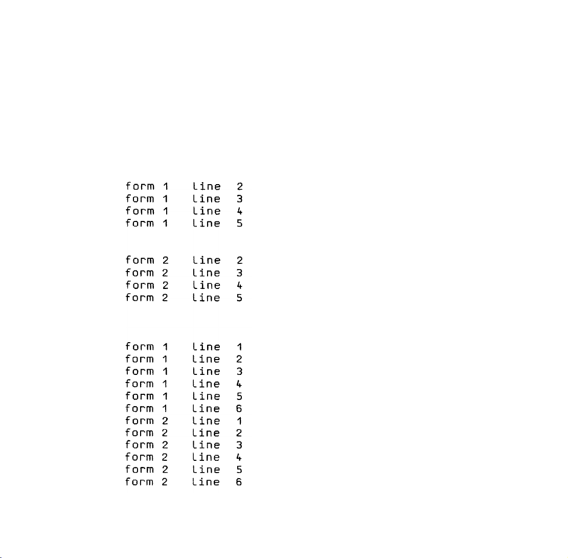
Page 12
Example 10 REM form length
20 LPRINT CHR$(27);"[4t";
30 FOR F=1 TO 2
40 FOR L=1 TO 3
50 LPRINT "length 4:form";F;" line";L
60 NEXT L:LPRINT CHR$(12);:NEXT F
70 LPRINT
80 LPRINT CHR$(27);"[3t";
90 FOR F=1 TO 3
100 FOR L=1 TO 2
110 LPRINT "length 3:form";F;" line";L
120 NEXT L:LPRINT CHR$(12);:NEXT F
130 END
6 Paper and Text Formatting
Page 13
Turn ON Positioning Unit Mode (SM) CSI 11 h
Turn OFF Positioning Unit Mode (RM) CSI 11
Data Structure ASCII CSI "1" "1" "h" [A] turn PUM ON
hex. 9B 31 31 68
dec. 155 49 49 104
l
ASCII CSI "1" "1" " " [A] turn PUM OFF
hex. 9B 31 31 69
dec. 155 49 49 105
Description PUM = Positioning Unit Mode
This mode decides, wether positioning commands or functions that deal with horizontal
or vertical position parameters, have characters and line positions as parameters or
some fixed units defined by the SSU control function (Select Size Unit, see the following
sequence).
If PUM is turned on and no unit is defined, the units shall default to decipoints (
inch).
If PUM is turned off, the units shall default to line or character distances.
By default the PUM mode is turned off. If PUM ist activated the accuracy cannot exceed
the vertical or horizontal resolution of your printer.
l
1
⁄
of an
720
Paper and Text Formatting 7
Page 14
Select Size Unit (SSU) CSI ... SP I
Data Structure ASCII CSI n SP "I" [B] select size unit
hex. 9B n SP 49
dec. 155 n SP 73
Description For n the following parameters are available:
n hex. dec. size unit
1
⁄
0 30 48 Decipoints (
1 31 49 Millimeters
2 32 50 Decipoints (0,0353 mm)
3 33 51 Decididots (0,0376 mm)
1
4 34 52 Mils (
⁄
1000
5 35 53 Basic Measuring Unit BMU (
6 36 54 Micrometer (0,001 mm)
7 37 55 Pixels
➊
This unit is machine dependent and may be of different size horizontally and vertically.
Page printers support typically 200, 300 or 600 dpi, matrix printers e.g. 180 or 360 dpi.
Example:
CSI 720 SP I
1B 55 37 32 30 20 49
results in one inch
inch = 0,0353 mm)
720
inch = 0,0254 mm)
1
⁄
inch = 0,02117 mm)
1200
➊
By default the size unit is the decipoint. Other size units may not be available due used
printer type.
PUM must be set to ON (see page 7)
8 Paper and Text Formatting
Page 15
Set Top and Bottom Margin CSI ... r
Clear Top and Bottom Margin CSI r
Data Structure ASCII CSI n
hex. 9B n
dec. 155 n
ASCII CSI "r" [A] clear top and bottom margin
hex. 9B 72
dec. 155 114
Description n
specifies the value of the top margin
1
specifies the value of the bottom margin
n
2
, n2= 1...132 lines at a line spacing of
n
1
= 1...176 lines at a line spacing of
Examples:
CSI n1 r set top margin, set bottom margin to default
CSI ; 0 r clear top and bottom margin
CSI ; n
r clear top margin, set bottom margin
2
Any change of margin settings is only effec tive fr o m th e ne xt pa g e on .
The setting of the top and bottom margins depends on the line spacing which is defined
before setting the margins. If line spacing is set after the setting of the top and bottom
margins, the margin positions on this page are not influenced.
If the form length is changed, the top margin is set to the first line, the bottom margin is
set to the last line (= form length).
";" n2"r" [A] set top and bottom margin
1
1
1
3B n
59 n
72
2
114
2
1
⁄
inch (6 lpi)
6
1
⁄
inch (8 lpi)
8
If there are any logical problems (for example, the settin g of top margin is larger then the
page length), the sequence i s ignored. If only one ma rgin is changed the other margi n
is automatically reset to the default value.
The unit depends on PUM and is either character positions or defined by the SSU function (Select Size Unit, see page 8).
Paper and Text Formatting 9
Page 16
Example 10 REM top and bottom margin
20 LPRINT CHR$(27);"[6t";:REM form length
30 LPRINT CHR$(27);"[2;5r":REM set margins
40 FOR F=1 TO 2
50 FOR L=2 TO 5
60 LPRINT "form";F;" line ";L
70 NEXT L:NEXT F
80 LPRINT
90 LPRINT CHR$(27);"[0;0r";:REM clear margins
100 FOR F=1 TO 2
110 FOR L=1 TO 6
120 LPRINT "form";F;" line ";L
130 NEXT L:NEXT F
140 END
10 Paper and Text Formatting
Page 17

Set Left and Right Margin CSI ... s
Clear Left and Right Margin CSI s
Data Structure ASCII CSI n
hex. 9B n
dec. 155 n
ASCII CSI "s" [A] clear left and right margin
hex. 9B 73
dec. 155 115
Description n
specifies the value of the left margin
1
specifies the value of the right margin
n
2
, n
n
1
2
Values for n
, n2 are valid for a line length of 8 inches (80 column printer) or 13.6 inches
1
(136 column printer) set in the printer menu.
Example:
CSI n1 s set left margin, set right margin to default
CSI s clear left and right margin
CSI ; n
s clear left marg in, se t righ t mar g in
2
";" n2"s" [A] set left and right margin
1
1
1
3B n
59 n
73
2
115
2
Print width 8 inches Print width 13,6 inches
= 1... 80 at 10 cpi = 1...136 at 10 cpi
= 1... 96 at 12 cpi = 1...163 at 12 cpi
= 1...120 at 15 cpi = 1...204 at 15 cpi
= 1...136 at 17.1 cpi = 1...232 at 17.1 cpi
= 1...160 at 20 cpi = 1...272 at 20 cpi
The setting of the left and right margins depends on the current character density.
Any later setting of the character density will not influence the positions of the left and
right margins on this page.
The unit depends on PUM and is either character positions or defined by the SSU function (Select Size Unit, see page 8).
Paper and Text Formatting
11
Page 18
If only one margin is changed, the other margin will be reset to default valu e.
If there are any logical problems (for example, left margin > right margin ), the sequen ce
is ignored.
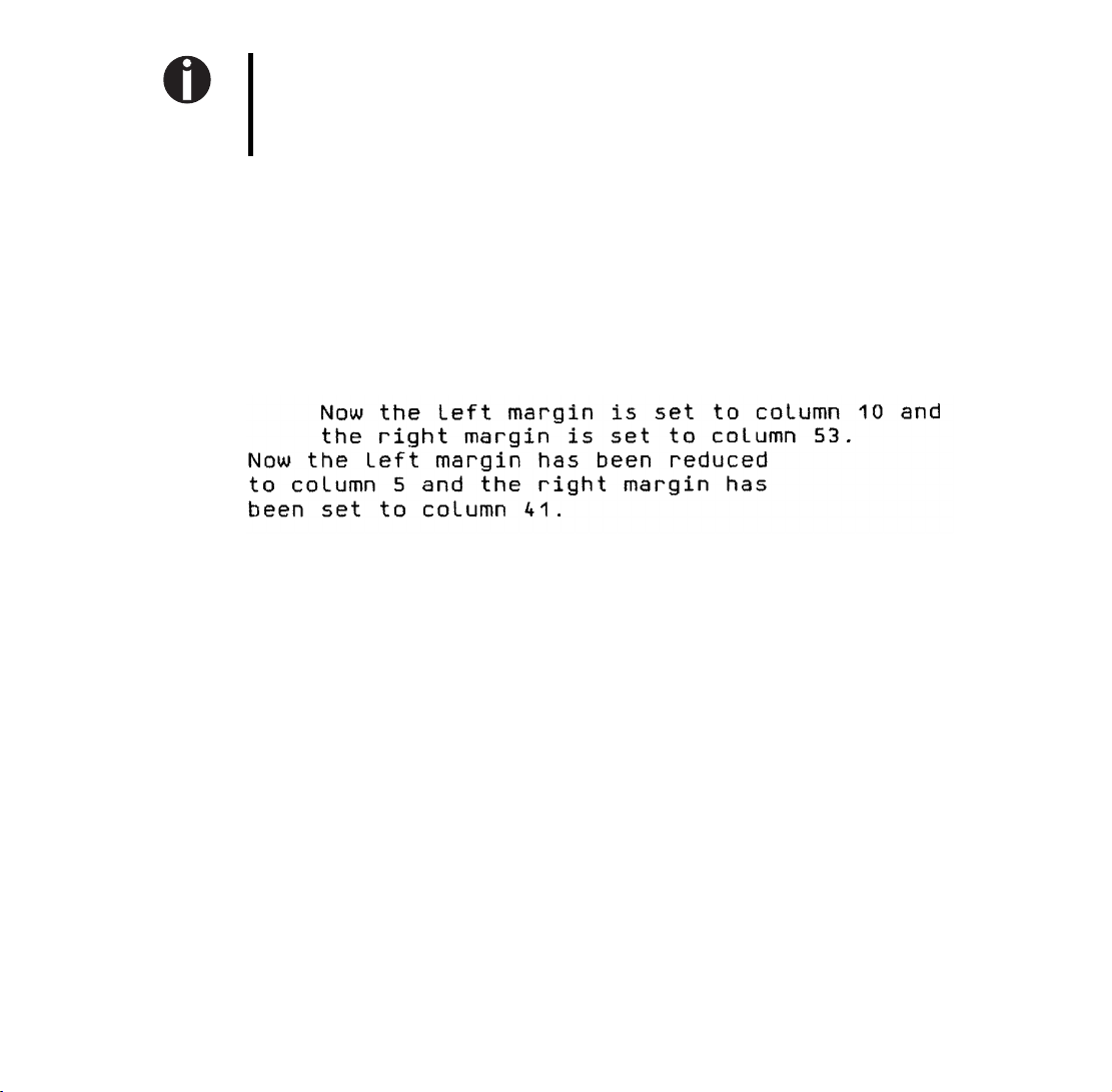
Example 10 REM left and right margin
20 WIDTH "LPT1:",255
30 LPRINT CHR$(27);"[10;53s";
40 LPRINT "Now the left margin is set to column 10 and the ";
50 LPRINT "right margin is set to column 53."
60 LPRINT CHR$(27);"[5;41s";
70 LPRINT "Now the left margin has been reduced to column 5 ";
80 LPRINT "and the right margin has been set to column 41."
90 END
12 Paper and Text Formatting
Page 19

Set Line Home (SLH) CSI ... SP U
Set Line Limit (SLL) CSI ... SP V
Data Structure ASCII CSI n SP "U" [A] set line home ➊
hex. 9B n 20 55
dec. 155 n 32 85
ASCII CSI n SP "V" [A] set line limit
hex. 9B n 20 55
dec. 155 n 32 85
Description n = 1...maximal print area
➊ Default setting: Physical left margin of medium or device.
n specifies the left margin. The first position is 1. The unit depends on PUM (Positioning
Unit Mode) and is either characters or defined by SSU (Select Size Unit, see page 8).
Example:
CSI SP U reset to physical left margin
CSI 10 SP U set left margin to position 10
➋ Default setting: Physical right margin (=1) of medium or device.
n specifies the right margin.
The unit depends on PUM (Positioning Unit Mode) and is either character positions or
defined by SSU (Select Size Unit, see page 8).
Example:
CSI SP V reset to physical right margin
CSI 80 SP V set right margin to position 80
➋
Paper and Text Formatting
13
Page 20

Right Justification ON CSI 8 y
Centering ON CSI 9 y
Right Justification and Centering OFF CSI 10 y
Right Justification and Centering OFF CSI : y
Data Structure ASCII CSI n "y" justification
hex. 9B n 79
dec. 155 n 121
Description For n the following characters are available:
n hex. dec. justification
8 38 56 [A] right justification ON
9 39 57 [A] centering ON ➋
10 31 30 49 48 [A] right justification and centering OFF
: 3A 58 [C] right justification and centering OFF
➊
➊ Leading blanks will not be corrected. Blanks at line end will be ignored.
➋ The text is centered between the active margins.
14 Paper and Text Formatting
Page 21
Character Spacing
Spacing Increment (SPI) CSI ... SP G
Data Structure ASCII CSI n
hex. 9B n
dec. 155I n
Description n
specifies the line spacing
1
specifies the character spacing
n
2
The unit is expressed in decipoints or other units defined by SSU (Select Size Unit, see
page 8).
For this note also the sequence “Set Line Spacing (SLS)” on page 26.
Example:
CSI 120 ; 0 G =∧ 6 lpi, basic cpi
CSI 90 ; 60 G =
The default setting of the spacing increment normally is 10 cpi.
n = 0: The distance is reset to the values set in the printer menu.
";" n2SP "G" [B] [C] set spacing increment
1
3B n220 47
1
59 n232 71
1
∧
8 lpi, 12 cpi
Character Spacing 15
Page 22
Horizontal Spacing CSI ... w
Data Structure ASCII CSI n "w" [A] set cpi
hex. 9B n 77
dec. 155 n 119
Description For n the following parameters are available:
n hex. dec. horizontal spacing
0 30 48 5 cpi
1 31 49 6 cpi
2 32 50 7,5 cpi
3 33 51 [B] [C] 8,6 cpi
4 34 52 10 cpi
5 35 53 12 cpi
6 36 54 15 cpi
7 37 55 [B] [C] 17,1 cpi
11 31 31 49 49 [B] [C] 20 cpi
12 31 32 49 50 [C] 10* cpi
10* cpi in this sequence means higher horizontal resolution of the printed characters
(emphasized printing), but lower print speed.
Various character densities can also be used within one line.
The default value for the character density is the printer menu setting.
16 Character Spacing
Page 23
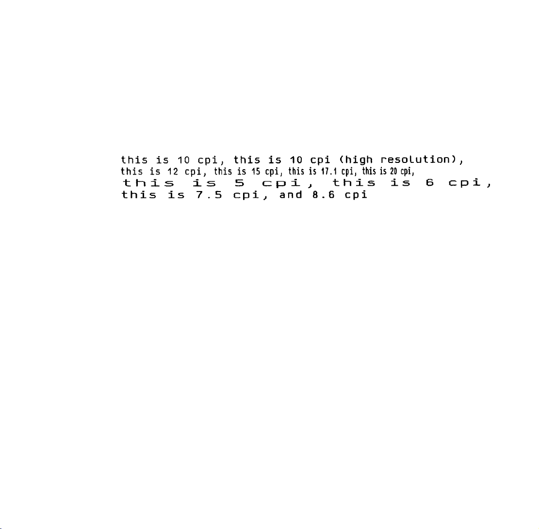
Example 10 REM character densities
20 LPRINT CHR$(27);"[4wthis is 10 cpi, ";
30 LPRINT CHR$(27);"[12wthis is 10 cpi (high resolution), "
40 LPRINT CHR$(27);"[5wthis is 12 cpi, ";
50 LPRINT CHR$(27);"[6wthis is 15 cpi, ";
60 LPRINT CHR$(27);"[7wthis is 17.1 cpi, ";
70 LPRINT CHR$(27);"[11wthis is 20 cpi, "
80 LPRINT CHR$(27);"[0wthis is 5 cpi, ";
90 LPRINT CHR$(27);"[1wthis is 6 cpi, "
100 LPRINT CHR$(27);"[2wthis is 7.5 cpi, ";
110 LPRINT CHR$(27);"[3wand 8.6 cpi"
120 END
Character Spacing 17
Page 24
Horizontal Character Spacing (SHS) CSI ... SP K
Data Structure ASCII CSI n SP "K" [A] set cpi
hex. 9B n 20 4B
dec. 155 n 32 75
Description For n the following parameters are available:
n hex. dec. character spacing
0 30 48 10 cpi
1 31 49 6 cpi
2 32 50 12 cpi
3 33 51 15 cpi
With this sequence the horizontal character spacing is defined.
The change of the character dimensions is implementation dependent.
18 Character Spacing
Page 25
Character Spacing (SCS) CSI ... SP g
Data Structure ASCII CSI n SP "g" [A] set character spacing
hex. 9B n 20 67
dec. 155 n 32 103
Description n specifies the character sp acin g
The unit is either decipoints or depends on the SSU selection (Select Size Unit, see page 8).
The character size will not be changed.
Character Spacing 19
Page 26

Additional Character Spacing (SACS) CSI ... SP \
Data Structure ASCII CSI n SP " \" [A] set additional character spacing
hex. 9B n 20 5C
dec. 155 n 32 92
Description n specifies the additional cha racter spacing
The units are either decipoints or defined by SSU (Select Size Unit, see page 8).
This function enlarges the inter character spacing. The function will typically be used with
proportional spacing to get effects like “spaced out” or right justifica tio n.
With fixed spacing, functions like SCS (Set Character Spacing, see previous page 19)
should be used.
The character size will not be changed.
20 Character Spacing
Page 27
Reduced Character Spacing (SRCS) CSI ... SP f
Data Structure ASCII CSI n SP "f" [B] set reduced character spacing
hex. 9B n 20 66
dec. 155 n 32 102
Description n specifies the reduced characte r spacing
The units are either decipoints or defined by SSU (Select Size Unit, see page 8).
This function reduces the inter character spacing. The function will typically be used with
proportional spacing to get special effects like e.g. kerning.
With fixed spacing, functions like SCS (Set Character pacing, see page 19 ) sh ou ld be
used.
The character size will not be changed.
Character Spacing 21
Page 28
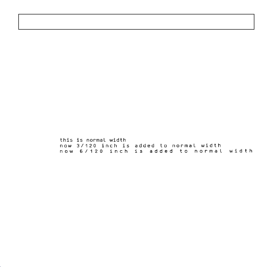
Horizontal Motion Index (HMI) CSI ... p
Data Sructure ASCII CSI n "p" [C] set HMI
hex. 9B n 70
dec. 155 n 112
Description n = 0...20
1
⁄
The normal character density is enlarged by n ∗
HMI is disabled.
inch. If n is set to zero (default setting),
120
Example 10 REM horizontal motion index
20 LPRINT "this is normal width"
30 LPRINT CHR$(27);"[3p";
40 LPRINT "now 3/120 inch is added to normal width"
50 LPRINT CHR$(27);"[6p";
60 LPRINT "now 6/120 inch is added to normal width"
70 END
22 Character Spacing
Page 29
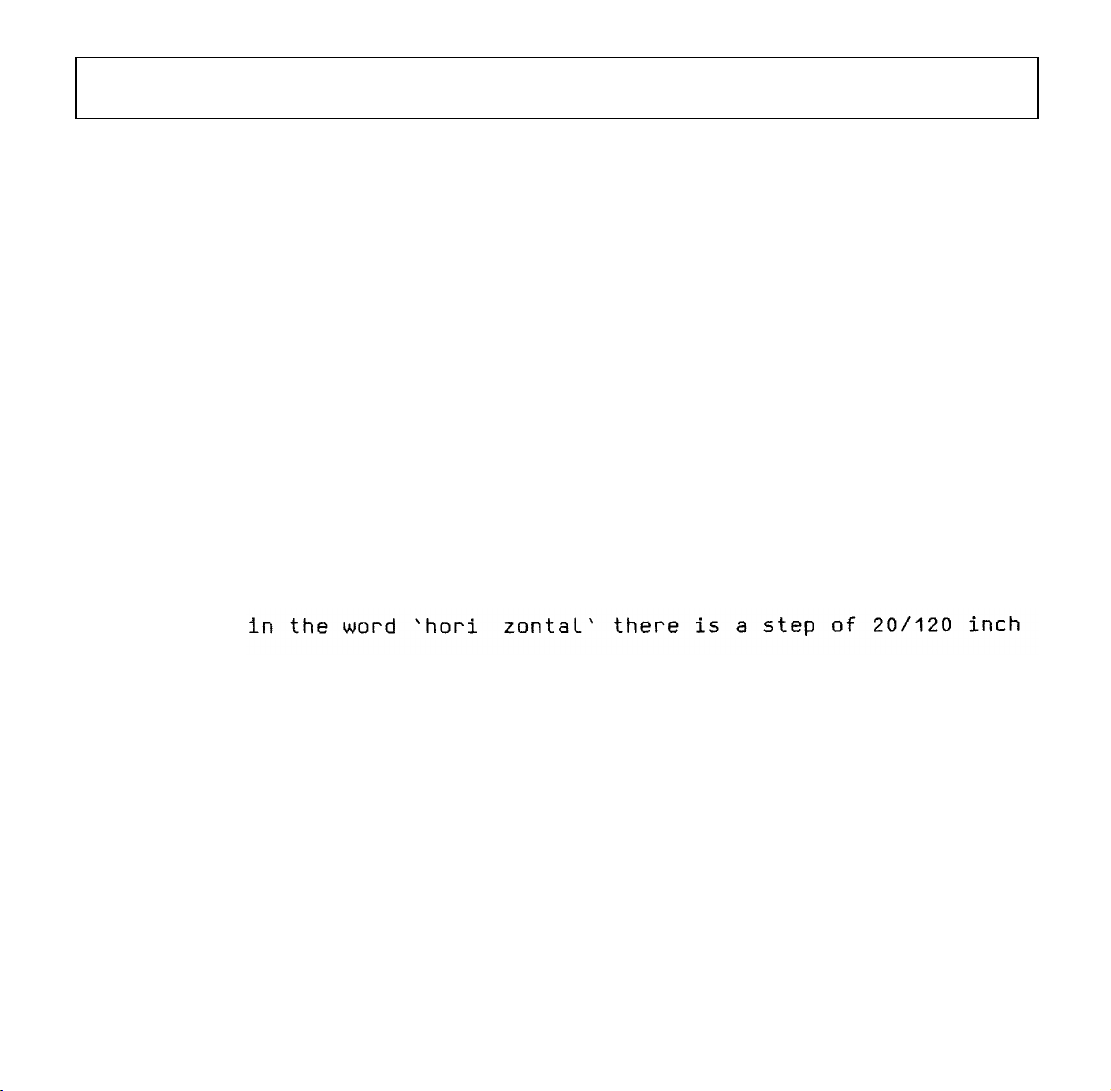
Horizontal Step (Microspace) CSI ... q
Data Structure ASCII CSI n "q" [C] set horizontal step
hex. 9B n 71
dec. 155 n 113
Description n = 1...255
1
⁄
The space between characters is enlarged by n ∗
Examples:
CSI q enlarging character space by n ∗1⁄
1
⁄
CSI 10 q inserts a
inch space
12
inch at the current print position.
120
inch
120
Example 10 REM horizontal step
20 LPRINT "in the word ‘hori";
30 LPRINT CHR$(27);"[20q";
40 LPRINT "zontal‘ there is a step of 20/120 inch"
50 END
Character Spacing 23
Page 30
Line Spacing
Vertical Spacing (SVS) CSI ... SP L
Data Structure ASCII CSI n SP "L" [A] set vertical spacing (lpi)
hex. 9B n 20 4C
dec. 155 n 32 76
Description For n the following parameters are available:
n hex. dec. vertical spacing
03048 6 lpi
13149 4 lpi
23250 3 lpi
33351 12 lpi
43452 8 lpi
93957 2 lpi
24 Line Spacing
Note that changing the line spacing also changes the number of lines per page.
Changing of line spacing does not affect the form length set before hand.
Page 31

Line Density 6 lpi CSI 3 z
Line Density 8 lpi CSI 4 z
Data Structure ASCII CSI "3" "z" [C] line density 6 lpi (= line spacing 1/6 inch)
hex. 9B 33 7A
dec. 155 51 122
ASCII CSI "4" "z" [C] line density 8 lpi (= line spacing 1/8 inch)
hex. 9B 34 7A
dec. 155 52 122
Description These sequences set the line spacing to
density).
Note that changing the line spacing also changes the number of lines per page.
Changing of line spacing does not affect the cur rent vertical tab stops or form length.
Example 10 REM line spacing
20 LPRINT CHR$(27);"[4z";
30 LPRINT "these two lines are printed with"
40 LPRINT "a spacing of 1/8 inch"
50 LPRINT
60 LPRINT CHR$(27);"[3z";
70 LPRINT "these two lines are printed with"
80 LPRINT "a spacing of 1/6 inch"
90 END
1
⁄
inch (6 lpi line density) or
6
1
⁄
inch (8 lpi line
8
Line Spacing 25
Page 32

Set Line Spacing (SLS) CSI ... SP h
Data Structure ASCII CSI n SP "h" [A] set line spacing
hex. 9B n 20 68
dec. 155 n 32 104
Description n specifies the line spacing
The unit is either decipoints or depends on the SSU selection (Select Size Unit, see page 8).
Note also the sequence SPI (Spacing Increment, see page 15) .
26 Line Spacing
Page 33

Character Styling
Superscript ON CSI 0 z
Subscript ON CSI 1 z
Microscript ON CSI 10 z
Super-/Sub-/Microscript OFF CSI 2 z
Data Structure ASCII CSI n "z" [A] character styling
hex. 9B n 7A
dec. 155 n 122
Description For n the following parameters are availble:
n hex. dec. character styling
0 30 48 superscript ON
1 31 49 subscript ON ➊
2 32 50 super-/sub-/microscript OFF ➋
10 31 30 49 48 microscript ON ➊
➊
These sequences switch the printer to superscript, subscript or microscript mode. The
1
⁄
subsequent characters are printed with about
or subscript characters are underlined, the underline character is printed at its normal
position.
of their normal height. If superscript
2
➊
➋ This sequence resets the printer to normal mode.
The base line for microprint is the same as for normal print.
The sequence CSI 2 z also resets double height.
(For this see also the following page 29, Double Height OFF)
Character Styling 27
Page 34

Example 10 REM super/sub/microscript
20 LPRINT "E=M*C";
30 LPRINT CHR$(27);"[0z";
40 LPRINT "2";
50 LPRINT CHR$(27);"[2z";
60 LPRINT " is Einsteins most famous formula."
70 LPRINT "H";
80 LPRINT CHR$(27);"[1z";"2";CHR$(27);"[2z";
90 LPRINT "O is simply water."
100 LPRINT "Micro";CHR$(27);"[10zscript";CHR$(27);"[2z";
110 LPRINT "is printed in the base line"
120 END
28 Character Styling
Page 35

Double Height ON (Upper Half) CSI 12 z
Double Height ON (Lower Half) CSI 13 z
Double Height OFF CSI 2 z
Data Structure ASCII CSI "1" "2" "z" [C] double height ON (upper half) ➊
hex. 9B 31 32 7A
dec. 155 49 50 122
Description
ASCII CSI "1" "3" "z" [C] double height ON (lower half)
hex. 9B 31 33 7A
dec. 155 49 51 122
ASCII CSI "2" "z" [A] double height OFF
hex. 9B 32 7A
dec. 155 50 122
➊
➋
➊ The same character must be sent to both lines to form a full character. Afterwards
double height must be reset. If only a part of the line is printed double height, the positioning of upper/lower half must be done by spaces. The line spacing should be set to
1
⁄
inch.
6
➋ This sequence also resets superscript, subscript and microscript.
Note: For selection of double height together with the proportional mode or other print
attributes the start of printing has to be identic for the top and bottom half.
Character Styling 29
Page 36

Example 10 REM double height
20 LPRINT "For ";CHR$(27);"[12zHeadlines ";CHR$(27);"[2z";
30 LPRINT "printing in double"
40 LPRINT CHR$(27);"[13z Headlines";CHR$(27);"[2z"
50 LPRINT "height is recommended"
60 END
30 Character Styling
Page 37

Print Quality CSI ... SP X
CSI ... y
Data Structure ASCII CSI n SP "X" [A] select print quality ➊
hex. 9B n 20 58
dec. 155 n 32 88
Description
ASCII CSI n "y" select print quality
hex. 9B n 79
dec. 155 n 121
➋
➊ This sequence defines the print quality. Print throughput changes with the print quality.
For n the following parameters are available:
(printer menu setting is valid)
n hex. dec. print quality
0 30 48 [A] [B] high
1 31 49 [A] medium
2 32 50 [A] low
➋ With the sequence CSI n y for n the following parameters are available:
n hex. dec. typeface
0 30 48 [A] draft print quality (DPQ)
1 31 49 [A] near letter quality (NLQ)
4 34 52 [C] NLQ at 10 cpi
5 35 43 [C] NLQ at 12 cpi
11 31 31 49 49 [B] fast draft print quality
12 31 32 49 50 [A] letter print quality (LQ) - e.g. 24∗36 matrix
13 31 33 49 51 [B] high resolution print quality - e.g. 24∗48 matrix
Character Styling
31
Page 38

Example 10 REM print quality
20 LPRINT CHR$(27);"[0yThis is draft quality ";
30 LPRINT CHR$(27);"[1yand this is NLQ printing."
40 LPRINT CHR$(27);"[5yThis is NLQ with 12 cpi."
50 END
32 Character Styling
Page 39

Select Typestyle CSI ... m
Data Structure ASCII CSI n "m" [A] select typestyle
hex. 9B n 6D
dec. 155 n 109
Description This sequence defines the typestyle.
For n the following parameters are available:
n hex. dec. typestyle (number is printer dependent)
10 31 30 49 48 font 0
11 31 31 49 49 font 1
12 31 32 49 50 font 2
13 31 33 49 51 font 3
14 31 34 49 52 font 4
15 31 35 49 53 font 5
16 31 36 49 54 font 6
17 31 37 49 55 font 7
18 31 38 49 56 font 8
19 31 39 49 57 font 9
0 30 48 clear all selected fonts
Depending on the value specified for n, one of the internal printer fonts or a font of an
optional font card is selected. Refer to the Operator’s Manual for information on printerresident fonts and font cards which can be installed.
The order of the font 0 to font 9 not corresponds to the fonts displayed on your printer.
The sequence and allocation is defined by the sequence CS I n
; n2 SP D (see FNT,
1
Font Selection, page 43).
A maximum of 16 CSI...m -sequences can be joined in one sequence: e.g. as follows:
; n2 ; nx m.
CSI n
1
Character Styling 33
Page 40

Example Valid for most MTPL printers.
Fontregister Font
0Draft
1 NLQ Courier
2LQ Courier
3 NLQ Sans Serif
4 LQ Sans Serif
5LQ Roman
6LQ Script
7 LQ Prestige
8 LQ OCR-B
9 LQ OCR-A
34 Character Styling
Page 41

Emphasized Mode ON CSI = z
Emphasized Mode OFF CSI > z
Data Structure ASCII CSI "=" "z" [C] emphasized mode ON
hex. 9B 3D 7A
dec. 155 61 122
ASCII CSI ">" "z" [C] emphasized mode OFF
hex. 9B 3E 7A
dec. 155 62 122
Description During printing in emphasized mode, each dot is printed twice , slight ly shifte d in ho riz on-
tal direction.
Emphasized mode can be used in all print qualities and character densities.
Example 10 REM emphasized mode
20 LPRINT CHR$(27);"[z";"this is printed in the normal mode"
30 LPRINT CHR$(27);"[=z";"and this in the emphasized one"
40 END
Character Styling 35
Page 42

Italic Mode ON CSI 3 m
Italic Mode OFF CSI 23 m
Data Structure ASCII CSI "3" "m" [A] italic mode ON
hex. 9B 33 6D
dec. 155 51 109
ASCII CSI "2" "3" "m" [A] italic mode OFF
hex. 9B 32 33 6D
dec. 155 50 51 109
The sequence CSI 0 m resets all CSI...m-sequences!
A maximum of 16 CSI...m -sequences can be joined in one seq uen ce , e.g . as fo llows:
CSI n
1;n2;nx
m
Example 10 REM italic mode
20 LPRINT CHR$(27);"[3m"
30 GOSUB 70
40 LPRINT CHR$(27);"[23m"
50 GOSUB 70
60 END
70 LPRINT "Matrix Printer"
80 RETURN
36 Character Styling
Page 43

Proportional Mode ON (SGR) CSI 26 m
CSI 2 y
Proportional Mode OFF CSI 50 m
CSI 7 y
Data Structure ASCII CSI "2" "6" "m" [A] proportional mode ON
hex. 9B 32 36 6D
dec. 155 50 54 109
ASCII CSI "2" "y" [C] proportional mode ON
hex. 9B 32 79
dec. 155 50 121
ASCII CSI "5" "0" "m" [A] proportional mode OFF
hex. 9B 35 30 6D
dec. 155 53 48 109
ASCII CSI "7" "y" [C] proportional mode OFF
hex. 9B 37 79
dec. 155 55 121
Description When in default font type, all characters are assigned a fixed, equally wide space.
When in proportional mode, the spaces between each character are set to the actual
width of the characters; on account of these “proportional spaces” reading of the text
becomes more easy.
Various font types basically are printed in proportional mode, e.g. Script, Kaufmann etc.
The sequence CSI 0 m resets all CSI...m-sequences!
A maximum of 16 CSI...m -sequences can be joined in one seq uen ce , e.g . as fo llows:
CSI n
1;n2;nx
m
Character Styling 37
Page 44
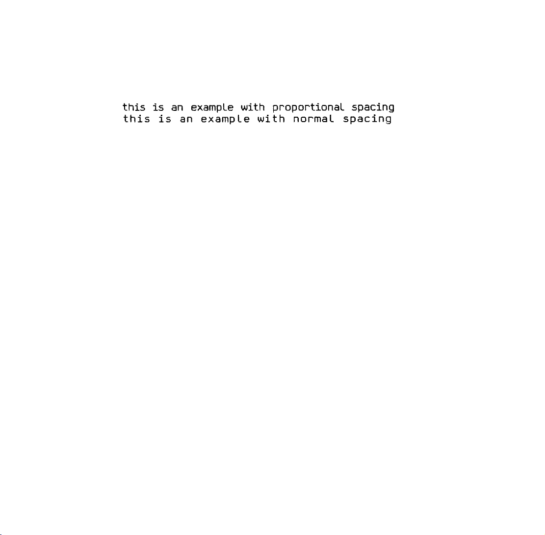
Example 10 REM proportional spacing
20 LPRINT CHR$(27);"[2y";
30 LPRINT "this is an example with proportional spacing"
40 LPRINT CHR$(27);"[7y";
50 LPRINT "this is an example with normal spacing"
60 END
38 Character Styling
Page 45

Underline Mode ON (SGR) CSI 4 m
Underline Double Mode CSI 21 m
Underline Mode OFF CSI 24 m
Data Structure ASCII CSI "4" "m" [A] underline mode ON ➊
hex. 9B 34 6D
dec. 155 52 109
ASCII CSI "2" "1" "m" [A] underline double mode
hex. 9B 32 31 6D
dec. 155 50 49 109
ASCII CSI "2" "4" "m" [A] underline mode OFF
hex. 9B 32 34 6D
dec. 155 50 52 109
Description
Example 10 REM underline mode
➊ All printed characters including spaces are automatically unerlined. Spaces between
tab codes (HT) are underlined.
The sequence CSI 0 m resets all CSI...m-sequences!
A maximum of 16 CSI...m -sequences can be joined in one seq uen ce , e.g . as fo llows:
CSI n
1;n2;nx
20 LPRINT "the most ";
30 LPRINT CHR$(27);"[4m";
40 LPRINT "important";
50 LPRINT CHR$(27);"[24m";
60 LPRINT " word must be underlined."
70 END
m
Character Styling 39
Page 46

Overline Mode ON (SGR) CSI 53 m
Overline Mode OFF CSI 55 m
Data Structure ASCII CSI "5" "3" "m" [A] overline mode ON
hex. 9B 35 33 6D
dec. 155 53 51 109
ASCII CSI "5" "5" "m" [A] overline mode OFF
hex. 9B 35 35 6D
dec. 155 53 53 109
Description This sequence switches the automatic overline function on or off. When the automatic
overline function is on, all printed characters including spaces are automatically underlined (also see SGR, Underline Mode ON, previous page 39).
The sequence CSI 0 m resets all CSI...m-sequences!
A maximum of 16 CSI...m -sequences can be joined in one seq uen ce , e.g . as fo llows:
CSI n
1;n2;nx
m
40 Character Styling
Page 47

Double Strike ON CSI 9 w
Double Strike OFF CSI 8 w
Data Structure ASCII CSI "9" "w" [B] [C] double strike print mode ON
hex. 9B 39 77
dec. 155 57 119
ASCII CSI "8" "w" [B] [C] double strike print mode OFF
hex. 9B 38 77
dec. 155 56 119
Description In double strike mode characters are pr in te d twice in two prin tin g pa sse s. Dou ble strike
mode can be used in all print qualities and character densities. Double strike mode can
also be used in combination with emphasiz ed mode.
STOP
Example 10 REM double strike
The use of this sequence in combination with LQ and emphasized printing is not
recommended.
20 LPRINT CHR$(27);"[8w";
30 LPRINT "this is normal printing";
40 LPRINT CHR$(27);"[9w";
50 LPRINT "and this is double strike printing"
60 END
Character Styling 41
Page 48

Graphic Size Selection (GSS) CSI ... SP C
Graphic Size Modification (GSM) CSI ... SP B
Data Structure ASCII CSI n SP "C" [B] graphic size selection ➊
hex. 9B n 20 43
dec. 155 n 32 67
Description
ASCII CSI n
hex. 9B n
dec. 155 n
;n
1
3B n
1
59 n
1
SP "B" [A] graphic size modification ➋
2
20 42
2
32 66
2
➊ n specifies the hight of the used font
The units are either decipoints or defined by the SSU function (Select Size Unit,
see page 8).
The width is implicitly defined by the height.
Example:
CSI 120 SP C set 12 point font (= 120 decipoints)
➋ n
specifies the he igh t of the us ed fonts (default setting: 100)
1
specifies its width (default setting: 100)
n
2
These parameters are given as a percent value of the size establishment by sequence
Example:
CSI SP B standard height and width
CSI 50 ; 50 SP B half sized characters (e.g. for indices or exp one n ts)
CSI 200 ; 200 SP B double sized characters (e.g. for headlines)
CSI 100 ; 67 SP B compresses a 10 pitch font for 15 cpi
➊.
If the selected character size is not printable, the next available character size is used.
42 Character Styling
Page 49

Font Designation (FNT) CSI ... SP D
Data Structure ASCII CSI n
hex. 9B n
dec. 155 n
Description n
= font number 0...9
1
= identification (ID) of the desired font
n
2
For n
the following parameters are available:
2
n
hex. dec. identification
2
0 30 48 Roman
1 31 49 Sans Serif
2 32 50 Courier
3 33 51 Prestige
4 34 52 Script
5 35 53 OCR B
6 36 54 OCR A
737 55 Modern
8 38 56 Kaufmann
9 39 57 Gothic
10 31 30 49 48 Swiss
11 31 31 49 49 Quadrato
66 36 36 54 54 Courier IBM
1;
3B n
1
59 n
1
n
SP "D" [A] designate font
2
20 44
2
32 68
2
The first parameter (n
) selects one of ten font registers to which the second parameter (n2)
1
designates one font of the whole repertory in the device. With the sequence CSI 1...m the
designated font can be selected (see page 33, Select Typestyle).
is in the range of zero to nine and selects primary font, first alternate font etc. up to the
n
1
nineth alternate font.
The second parameter (n
) is defined by your printer type and represents an identification
2
of the desired font.
Character Styling
43
Page 50

Font attributes, e.g. “bold” can be specified after designation through cor responding ESC
sequences.
Technical Details
Font Designation
Codes
The use of the font designation code CSIn
space D needs further explanation. (Note :
1;n2
CSI is 9B; you can use ESC[, 1B 5BH, instead if you wish.)
The parameter n
Register to use.
1
This paramer can take values of 0 to 9. The default allocation of fonts to these registers is
given in the printer’s manual.
The parameter n
What to put in the register.
2
This parameter is held as a 16 bit number in the printer. It is made up as below:
The lower eight bits (0 to 255)
These encode the typeface and are as given in the manual with the exception that 5 is
OCR-B and 6 is OCR-A.
0 = Roman 1 = Sans Serif 2 = Courier 4 = Script
5 = OCR-B 6 = OCR-A 7 = Modern 8 = Kaufmann
9 = Gothic 10 = Helvette 11 = Quadrato 66 = Courier IBM
The upper eight bits
Only bits 9 (512H) and 11 (2048H) are used. All the other bits must be left at 0. Bits 9 and
11 set print quality: Bit 11 Bit 9
0 0 Letter Quality
01Draft
1 0 Near Letter Quality
11Reserved
When Draft (01) is selected the lower eight bits have a new meaning:
0 = Multicopy Draft 1 = Fast Draft 2 = Normal Draft
to specify a type face with a print quality add the decimal values and convert to an ASCII
string.
Example 1: Courier LQ = 00 + 2 Number = 2
Example 2: Script NLQ = 10 (2048) + 4 Number = 2052
Example 3: Draft = 01 (512) + 1 Number = 513
So CSI7;513 D i.e.: 9B 37 3B 35 31 33 20 44H (or ESC[7;513 D i.e. 1B 5B 37 3B 35 31
33 20 44 H) will put Fast Draft in font register 7. The sequence ESC[17m will select this
register as the font to use.
44 Character Styling
Page 51

Print Positioning
Horizontal Tab Stop HT
Data Structure ASCII HT [A] horizontal tab stop
hex. 09
dec. 9
Description The HT-Code moves the active print position to the next horizontal tabulation stop on the
same line. If there is no tab stop reachable - no more tab stops are set or the next tab
stop is beyond the defined right margin - spaces are inserted.
The graphic renditions, e.g. underlining, overscoring etc., being active during the tab is executed, apply also to the whitespace produced by two tab stops.
Set Horizontal Tab Stop at Current Position HTS
Data Structure ASCII HTS [A] set horizontal tab stop
hex. 88
dec. 136
Description This code sets a tab stop at the current horizontal position.
Print Positioning
45
Page 52

Horizontal Tab Stops ON CSI ... u
ESC H
Horizontal Tab Stops OFF (TBC) CSI ... g
Data Structure ASCII CSI n
hex. 9B n
dec. 155 n
ASCII ESC "H" [C] set horizontal tab stop at current position
hex. 1B 48
dec. 27 72
ASCII CSI n "g" [A] clear all horizontal tab stops
hex. 9B n 67
dec. 155 n 103
Description
➊ Print width 8 inches Print width 13,6 inches
n
1
Values for n
(136-column printer) set in the menu.
Up to 16 tab stops can be joined in one sequence as follows:
CSI n
1
The parameters do not have to be sorted. The positions of the horizontal tab stops depend
on the current character density.
are valid for a line length of 8 inches (80-column printer) or 13.6 inches
1
; n2 ; n3 ; ... ; n16 u
"u" [A] set horizontal tab stop ➊
1
75
1
117
1
= 1... 80 at 10 cpi = 1...136 at 10 cpi
= 1... 96 at 12 cpi = 1...163 at 12 cpi
= 1...120 at 15 cpi = 1...204 at 15 cpi
= 1...136 at 17.1 cpi = 1...232 at 17.1 cpi
= 1...160 at 20 cpi = 1...272 at 20 cpi
➋
➌
➋ This sequence is interpreted as a Epson/IBM-sequence (ESC H =
46 Print Positioning
tion MTPL+Epson/IBM is set.
∧
LQ off), if the emula-
Page 53

➌ With the sequence CSI n g for n the follo wing pa ra mete rs ar e ava ila ble:
n hex. dec. function
0 30 48 clear horizontal tab stop at current position
2 32 50 clear all horizontal tab stops in current line
3 33 51 clear all horizontal tab stops in all lines
Examples:
CSI g clear horizontal tab stop at current position
CSI 3;4 g clear all horizontal and vertical tab stops
(for this also see page 52, Vertical Tab Stops ON/OFF)
Later changes of character density will not influence the physical position of the tab
stops.
A horizontal tabulation is executed by the HT control code (hex.09, dec.9); for this see
page 45, Horizontal Tab Stop.
Print Positioning 47
Page 54

Example 1 10 REM horizontal tabs
20 LPRINT CHR$(27);"[4w";:REM 10 cpi
30 LPRINT CHR$(27);"[10;20;30u";
40 LPRINT "123456789012345678901234567890123456789"
50 GOSUB 110
60 LPRINT CHR$(27);"[0w";:REM 5 cpi
70 GOSUB 110
80 LPRINT CHR$(27);"[11w";:REM 20 cpi
90 GOSUB 110
100 END
110 LPRINT CHR$(9);"tab1";
120 LPRINT CHR$(9);"tab2";
130 LPRINT CHR$(9);"tab3"
140 RETURN
Example 2 10 FOR I=1 TO 3
20 LPRINT "1234567890";CHR$(27);"H";
30 NEXT I
40 LPRINT
50 FOR J=1 TO 3
60 LPRINT CHR$(9);"tab";
70 NEXT J
80 LPRINT
90 END
48 Print Positioning
Page 55

Line Feed LF
Data Structure ASCII LF [A] line feed
hex. 0A
dec. 10
Description When the printer receives this code, it prints all the data in the print buffer, then advances
the paper one line.
The LF code can also give a carriage return if automatic carriage return is selected. If no
CR is given, the next printing starts in the column following the end of printing.
The amount by which the paper is advanced depends on the current line spacing. The
1
⁄
default line spacing of the printer is
inch.
6
Print Positioning
49
Page 56

Vertical Tab Stop VT
Data Structure ASCII VT vertical tab stop
hex. 0B
dec. 11
Description When the printer receives this code, it prints all the data in the print buffer, then advances
the paper to the next vertical tab stop position.
The VT code can also give a carriage return if automatic carriage return is selected (refer
to Operator’s Manual). If no CR is given, the next printing starts in the column following
the end of printing.
The amount by which the paper is advanced depends on the current line spacing. After
switching on the printer no vertical tab stops are set (defau lt con fig ur atio n) . If th er e are no
vertical tab stops between the current print position and the end of the page, or if there
are no vertical tab stops set, VT assumes the same function as LF.
50 Print Positioning
Page 57

Set Vertical Tab Stop at Current Position VTS
Data Structure ASCII VTS [A] set vertical tab stop
hex. 8A
dec. 138
Description This code sets an horizontal tab stop at the current vertical position.
Vertical Index IND
Data Structure ASCII IND [A] vertical index
hex. 84
dec. 132
Description The code IND moves the active print position to the following line. The difference to Line
Feed (LF) is that IND does not permit an CR option.
Print Positioning
51
Page 58

Vertical Tab Stops ON CSI ... v
Vertical Tab Stops OFF (TBC) CSI 1 g
CSI 4 g
Data Structure ASCII CSI n "v" [A] set vertical tab stop ➊
hex. 9B n 76
dec. 155 n 118
ASCII CSI "1" "g" [A] clear all vertical tab stops at current position
hex. 9B 31 67
dec. 155 49 103
ASCII CSI "4" "g" [A] clear all vertical tab stops
hex. 9B 34 67
dec. 155 52 103
Description
➊ n = 1...132 lines at a line spacing of
52 Print Positioning
1
⁄
inch (6 lpi)
6
1
⁄
= 1...176 lines at a line spacing of
Up to 16 tab stops can be joined in one sequence as follows:
; n2 ; n3 ; ... ; n16 v
CSI n
1
The parameters do not have to be sorted. The positions of the horizontal tab stops
depend on the current character density.
inch (8 lpi)
8
Examples:
CSI g clear horizontal tab stop at current position
CSI 3;4 g clear all horizontal and vertical tab stops
(for this also see page 46, Horizontal Tab Stops ON/OFF)
Later changes of character density will no t influence the physical position of the tab stops.
Page 59

A vertical tabulation is executed by the VT control code (hex.0B, dec.11); also see page 50,
Vertical Tab Stop.
Example 10 REM vertical tabs
20 LPRINT CHR$(27);"[10t";:REM set form length
30 LPRINT CHR$(27);"[4g";:REM clear all vtabs
40 LPRINT CHR$(27);"[3;5;9v";
50 LPRINT CHR$(11);"this is the first vertical tab, line 3"
60 LPRINT CHR$(11);"this is the second vertical tab, line 5"
70 LPRINT CHR$(11);"this is the third vertical tab, line 9"
80 END
Print Positioning 53
Page 60

Horizontal Posititon Absolute (HPA) CSI ... ’
Data Structure ASCII CSI n " ‘ " [A] set horizontal position absolute
hex. 9B n 60
dec. 155 n 96
∧
Description n = 1 (default setting) =
This sequence moves the print head to a horizontal print position absolute.
The unit depends on PUM (Positioning Unit Mode) and is either character positions or
defined by the SSU-function (Select Size Unit, see page 8).
Example:
CSI 40 ‘ next character goes to position 40
CSI ‘ next character goes to the left margin
Positions outside the right margin are ignored.
current left margin
54 Print Positioning
Make sure you do not confuse the character “
‘ ” with the apostrophe “ ’ ” !
Page 61

Horizontal Position Relative (HPR) CSI ... a
Data Structure ASCII CSI n "a" [A] set horizontal position relative
hex. CSI n 61
dec. CSI n 97
Description n = 1 (default setting)
This sequence moves the print head to the right.
The unit depends on PUM (Positioning Unit Mode) and is either character positions or
defined by the SSU-function (Select Size Unit, see page 8).
Example:
CSI 8 a next character goes 8 positions to the right
CSI a next character goes one position to the right
Positions beyond the right margin are ignored.
Print Positioning 55
Page 62

Horizontal Position Backward (HPB) CSI ... j
Data Structure ASCII CSI n "j" [A] set horizontal position backward
hex. 9B n 6A
dec. 155 n 106
Description n = 1 (default setting)
This sequence moves the print head to the left.
The unit depends on PUM (Positioning Unit Mode) and is either character positions or
defined by the SSU-function (Select Size Unit, see page 8).
Example:
CSI 8 j next character goes 8 positions to the left
CSI j next character goes one position to the left
Positions outside the left margin are ignored.
56 Print Positioning
Page 63

Vertical Position Absolute (VPA) CSI ... d
255031-001A
Data Structure ASCII CSI n d [A] set vertical position absolute
hex. 9B n 64
dec. 155 n 100
∧
Description n = 1 (default setting) =
This sequence moves the print head to a vertical print position absolute.
The unit depends on PUM (Positioning Unit Mode) and is either lines or defined by the
SSU-function (Select Size Unit, see page 8).
Example:
CSI 40 d move the active print position to line (or vertical position) 40
CSI d move the active print position to top margin
Positions outside the bottom margin are ignored.
current top margin
Print Positioning 57
Page 64

Vertical Position Relative (VPR) CSI ... e
Data Structure ASCII CSI n "e" [A] set vertical position relative
hex. 9B n 65
dec. 155 n 101
Description n = 1 (default setting)
This sequence moves the print head lines or vertical positions down.
The unit depends on PUM (Positioning Unit Mode) and is either lines or defined by the
SSU-function (Select Size Unit, see page 8).
Example:
CSI 12 e move print position 12 lines (or vertical positions) down
CSI e move print position one line down
Positions beyond the bottom margin are ignored.
58 Print Positioning
Page 65

Vertical Position Backward (VPB) CSI ... k
Data Structure ASCII CSI n "k" [A] set vertical position backward
hex. 9B n 6B
dec. 155 n 107
Description n = 1 (default setting)
This sequence moves the print head lines or vertical positions upward.
The unit depends on PUM (Positioning Unit Mode) and is either lines or defined by the
SSU-function (Select Size Unit, see page 8).
Positions beyond the top margin are ignored. This sequ ence is not valid in Single Sheet
Mode.
Print Positioning 59
Page 66

Horizontal and Vertical Position Absolute (HVP) CSI ... f
Data Structure ASCII CSI n1 ;n2"f" [B] [C] set horizontal and vertical position absolute
hex. 9B n
dec. 155 n
3B n266
1
59 n2102
1
Description n
= vertical position
1
= horizontal position
n
2
This sequence moves the print head to a horizontal and vertical print position absolute.
The unit depends on PUM (Positioning Unit Mode) and is either lines or defined by the
SSU-function (Select Size Unit, see page 8).
Example:
CSI f move the print position to the top left position on page
CSI 20 ; 35 f move the print position to line (vertical position) 20 and horizontal
character position 35
(if PUM is turned off)
Note that during manual and automatic cut sheet feeding your printer can only reverse
the form a limited distance.
60 Print Positioning
Page 67

Backspace BS
Data Structure ASCII BS [A] Backspace
hex. 08
dec. 8
Description After receiving this code the content of line buffer is printed out.
Then, the print head is moved one position to the left (depending on the current values
of cpi).
Carriage Return CR
Data Structure ASCII CR [A] carriage return
hex. 0D
dec. 13
Description When the printer receives this code, it prints any data in the print buffer and resets the
line pointer. The active print position is set to the left margin (first possible character position).
The code CR can also give a line feed if automatic line feed is selected (refer to Operator’s Manual).
Print Positioning
61
Page 68

Form Feed FF
Data Structure ASCII FF [A] form feed
hex. 0C
dec. 12
Description When the printer receives this code, it prints the data in the print buffer, then advances
the paper from the current pritn position to the top-of-form position on the next page.
Cut sheet:
Forms are ejected. The first print position on the following paper is the first (top) physically possible position.
Fanfold paper:
The paper is moved by the form length given before. The first print position on the following paper is the first (top) physically possible position.
The FF code can also give a carriage return if automatic carriage return is select ed (refer
to Operator’s Manual). The next print is started in the column following the print end of
the last print-out if no CR is transmitted.
After switching on the printer the default form length is set to 12 inches (72 lines) per
page (Europe 12"; USA 11").
62 Print Positioning
Page 69
Partial Line Down PLD
Data Structure ASCII PLD [A] partial line down
hex. 8B
dec. 139
Description If the preceding character is in normal position, PLD moves the active position down to a
sufficient distance to give the following characters the appearence of being subscripted.
If the preceding character is in a superscript position, PLD moves to normal position.
Partial Line Up PLU
Data Structure ASCII PLU [A] partial line up
hex. 8C
dec. 140
Description If the preceding character is in normal position, PLU moves the active position up a
sufficient distance to give the following characters the appearence of being superscripted.
If the preceding character is in a subscript position, PLU moves to normal position.
Print Positioning
63
Page 70

Reverse Index RI
Data Structure ASCII RI [B] reverse index
hex. 8D
dec. 141
Description The code RI moves the active position to the preceding line. An CR option is not permitted.
Next Line NEL
Data Structure ASCII NEL [B] next line
hex. 85
dec. 133
Description The code NEL moves the active position to the left margin of the next line. This gives th e
same result as the combination of CR (Carrigage Return) and LF (Line Feed).
64 Print Positioning
Page 71

Graphics
Graphic Modes ESC % ...
CSI 6 z
CSI 5 z
Data Structure ASCII ESC "%" n n1;n
hex. 1B 25 n n
dec. 27 37 n n
ASCII CSI "6" "z" [C] graphics invers
hex. 9B 36 7A
dec. 155 54 122
ASCII CSI "5" "z" [C] graphics unchanged
hex. 9B 35 7A
dec. 155 53 122
Description For n the following parameters are available:
n dpi
3 33 51 graphics 60 dpi
4 34 52 graphics 120 dpi
5 35 53 graphics 80 dpi
6 36 54 graphics 240 dpi
7 37 55 graphics 240 dpi
8 38 56 graphics 72 dpi
9 39 57 graphics 90 dpi
Data following the graphic-CSI-sequence are printed out as dot pattern. n
the length of the data sequence.
1
1
3B n
59 n
2
2
2
; DATA [C] set dpi for graphics
3B DATA
59 DATA
and n2 define
1
Graphics
65
Page 72

The vertical resolution is 72 dpi.
The graphics image is printed vertically closed at a line feed of
sequences Spacing Increment (SPI), page 15, and Set Line Spacin g (SLS), page 26.
Example: CSI 80 ; SP G).
Example for calculation of n1 and n2:
The length of graphics is 80 bytes.
n
= number of bytes divided by 256
2
= int (
= dec.0
= hex.00
= remainder of division of n
n
1
= 80 mod 256
= dec.80
= hex.50
Graphics data and text data can be mixed within one line.
Relationship between graphics data and needles:
80
⁄
)
256
2
Needle Data byte
1/3
4/5
6/8
9/10
11/13
14/15
16/18
19/20
•
•
•
•
•
•
•
•
Bit 7
Bit 6
Bit 5
Bit 4
Bit 3
Bit 2
Bit 1
Bit 0
80
⁄
inch. (Also see the
720
66 Graphics
Page 73

Relationship between graphics data and needles:
Needle Data byte
1
•
2
•
3
•
4
•
5
•
6
•
7
•
8
•
Bit 7
Bit 6
Bit 5
Bit 4
Bit 3
Bit 2
Bit 1
Bit 0
Example 1 10 REM bit image print
20 WIDTH "LPT1:",255
30 LPRINT CHR$(27);"%3";CHR$(80);CHR$(0);
40 GOSUB 100:LPRINT " 60 dpi"
50 LPRINT CHR$(27);"%4";CHR$(80);CHR$(0);
60 GOSUB 100:LPRINT " 120 dpi"
70 LPRINT CHR$(27);"%7";CHR$(80);CHR$(0);
80 GOSUB 100:LPRINT " 240 dpi"
90 END
100 FOR N=1 TO 80
110 LPRINT CHR$(255);
120 NEXT N
130 RETURN
Graphics 67
Page 74

Example 2 10 REM bit image print
20 WIDTH "LPT1:",255
30 LPRINT CHR$(27);"%3";CHR$(10);CHR$(0);
40 GOSUB 130:REM 60 dpi
50 LPRINT CHR$(27);"%4";CHR$(10);CHR$(0);
60 GOSUB 130:REM 120 dpi
70 LPRINT CHR$(27);"[6z";
80 LPRINT CHR$(27);"%3";CHR$(10);CHR$(0);
90 GOSUB 130:REM reverse 60 dpi
100 LPRINT CHR$(27);"[5z";
110 LPRINT
120 END
130 RESTORE
140 FOR I=1 TO 10
150 READ D
160 LPRINT CHR$(D);
170 NEXT I
180 LPRINT " ";
190 RETURN
200 DATA 34,80,138,0,143,0,138,80,34,0
68 Graphics
Page 75

Miscellaneous
Load Menu CSI ... SP q
Data Structure ASCII CSI n SP "q" [B] load menu
hex. 9B n 20 71
dec. 155 n 32 113
Description For n the following parameters are available:
n hex. dec. Loading of
0 30 48 Default menu
1 31 49 Menu No. 1
2 32 50 Menu No. 2
3 33 51 Menu No. 3
4 34 52 Menu No. 4 (reserved)
Up to 3 (4) various configurations can be saved with the printer.
Setting the configuration is made by the control panel of the printer (refer to Operator’s
Manual, chapter 2, “Menu”).
Example:
CSI 0 SP q or CSI SP q load default menu
By using this sequence all settings changed by sequences are reset!
Miscellaneous 69
Page 76

Automatic Gap Adjustment (AGA) CSI ... + z
Direct Setting of the Print Head Distance CSI ... + y
Data Structure ASCII CSI n "+" "z" [B] automatic gap adjustment ➊
hex. 9B n 2B 7A
dec. 155 n 43 122
Description
ASCII CSI n "+" "y" [B] direct setting of the print head distance
hex. 9B n 2B 79
dec. 155 n 43 121
➊ For the sequence CSI n + z the following parameters are available for n:
n hex. dec. Adjustment (automatic)
0 30 48 automatic adjustment OFF
(print head distance must be set at the printer)
1 31 49 automatic adjustment ON
➋ For the sequence CSI n + y the following parameters are available for n:
n hex. dec. Setting (direct)
0 30 48 Default value
(is set at the printer)
n
Setting the print head distance accords to the respective paper path selected. Unit, adjust
range and default setting depend on the device used.
If the Automatic Gap Adjustment is set to ON, the sequence
print head distance in n -steps
is ignored.
➋
➋
70 Miscellaneous
Example:
Settings of T2060: Unit = 10 Micrometers
Adjust range = 1 – 100
Default value = 18
Page 77

Paper Handling CSI Ps1 Ps2 Ps3 Pn4 Pn5 + v
Data Structure ASCII CSI Ps1 Ps2 Ps3 Pn4 Pn5 "+" "v"
hex. 9B Ps1 Ps2 Ps3 Pn4 Pn5 2B 76
dec. 155 Ps1 Ps2 Ps3 Pn4 Pn5 43 118
Description Ps1 missing or 0: Printhead does not lift off at the fold
1: Printhead lifts off at the fold
Ps2 missing or 0: Printhead position at left margin during paper movement
allowed
1: Printhead position at left margin during paper movement
not allowed
Ps3 missing or 0: Printhead position at right margin during paper movement
allowed
1: Printhead position at right margin during paper movement
not allowed
Pn4 missing or <20 or >136: No limitation of print width
20 … 136: Print width in 1/10 inch
Pn5 missing or 0 or >30: No displacement of the start of the print area (left margin);
1 … 20: Displacement of the start of the print area in 1/10 inches
Shared Interface CSI Pn + w
Data Structure ASCII CSI Pn "+" "w"
hex. 9B Pn 2B 77
dec. 155 Pn 43 119
Description Sequence to set hold time of shared I/O after selecting alternate interface.
Pn missing or 0: Sequence ignored
Pn 1 … 30: Hold time in seconds
Shared I/O has to be selected in the printer’s menu. Default = 30 s.
Miscellaneous 71
Page 78
Color Selection (Option) CSI ... m
Data Structure ASCII CSI n "m" [A] set colors
hex. 9B n 6D
dec. 155 n 109
Description For n the following parameters are available:
n hex. dec. color selection
0 30 48 reset color
1 31 49 bold or increased intensity
2 32 50 alternate color or decreased intensity
22 32 32 50 50 cancels functions of parameters 1 and 2
(normal color or normal intensity)
30 33 30 51 48 black
31 33 31 51 49 red
32 33 32 51 50 green
33 33 33 51 51 yellow
34 33 34 51 52 blue
35 33 35 51 53 magenta-red
36 33 36 51 54 cyan-blue ➋
39 33 39 51 57 default color blac
➊
➋
➋
➊ red or magenta, depending on the ribbon used
➋ only available with multi color ribbon
The available colors depend on the ribbon used and must be matched in the menu . If a
ribbon with several black tracks is used, then it is automatically switched every new page
between the tracks.
The relationship between tracks and colors is shown in the following table:
track yellow, cyan,
72 Miscellaneous
red, green, blue, black
magenta, black
(YMCK)
1 black black black
2 cyan blue black
3 magenta green black
4 yellow red red
(RGBK)
3 ∗ black, red
Page 79

The relationship between color selection sequences and the resultin g colo rs for seve ral
ribbon cassettes is shown in the following table:
selected
color
black black black black
red red *) red red
green green **) green ****)
yellow yellow green ****)
blue blue ***) blue ****)
magenta magenta red red
cyan cyan blue ****)
* red = yellow + magenta
** green = yellow + cyan two-pass print is automatically executed
*** blue = magenta + cyan
**** sequence is ignorered
The sequence CSI 0 m resets all CSI...m -sequences! A maximum of 16 CSI...m
-sequences can be joined in one sequence: e.g. CSI n
Example 10 REM color selection
20 LPRINT CHR$(27);"[31m";
30 LPRINT "this is written with red colour"
40 LPRINT CHR$(27);"[34m";
50 LPRINT "this is written with blue colour"
60 END
yellow, magenta, cyan,
black
(YMCK)
}
red, green, blue,
black
(RGBK)
1;n2;nx
3 ∗ black, red
m.
Miscellaneous 73
Page 80

Input Data Control CSI ... z
Data Structure ASCII CSI "9" "z" [C] set bit 8 = 1 ➊
hex. 9B 39 7A
dec. 155 57 122
Description
STOP
ASCII CSI "8" "z" [C] set bit 8 = 0
hex. 9B 38 7A
dec. 155 56 122
ASCII CSI "7" "z" [C] bit 8 unchanged
hex. 9B 37 7A
dec. 155 55 122
➋
➊ By means of this MTPL-sequence the eighth data bit is set to “1”.
This results in accordance with the selected character set characters from the national
character set or italic characters to be pr inted.
➋ By means of this MTPL-sequence the eighth data bit is set to “0”.
This means that wrong character printing caused by the eighth data bit set high by the
system can be avoided.
CSI 9 z is ignored
– if Extended Character Set is selected,
– if Graphic Mode is selected
Note that following the sequence CSI 8 z all subsequent control sequences must begin
with an “ESC [ ”, because CSI (9B) cannot be represented by a 7 bit code. This remains
in effect until the printer receives eithe r th e seq u en ce ESC [ 9 z or ESC [ 7 z .
74 Miscellaneous
Page 81

Example 10 REM input data control
20 LPRINT CHR$(27);"[7z";
30 GOSUB 90
40 LPRINT CHR$(27);"[9z";
50 GOSUB 90
60 LPRINT CHR$(27);"[8z";
70 GOSUB 90
80 END
90 FOR I=97 TO 103:LPRINT CHR$(I);:NEXT I
100 FOR I=161 TO 167:LPRINT CHR$(I);:NEXT I
110 LPRINT:LPRINT
120 RETURN
Miscellaneous 75
Page 82

Sheet Feeder/Paperway CSI ... {
Eject Form CSI 2 J
Data Structure ASCII CSI n ; n
hex. 9B n 3B n
dec. 155 n 59 n
ASCII CSI "2" "J" [C] eject form
hex. 9B 32 4A
dec. 155 50 74
Description With the sequence CSI n ; n
n hex. dec. sheet feeder
0 30 48 cut sheet paper (manual)
5 35 53 fanfold paper (tractor 1) ➌
6 36 54 fanfold paper (tractor 2) ➍
21 32 31 50 49 bin 1 (front) ➎
22 32 32 50 50 bin 2 (rear) ➎
23 32 33 50 51 bin 3 (reserved) ➏
31 33 31 51 49 stacker 1 of the sorter ➐
50 35 30 53 48 move paper to normal print position ➑
51 35 31 53 49 move paper to tear-off position
52 35 32 53 50 move paper to view position ➓
51 35 31 53 49 cuts fanfold paper at the next perforation ➀
54 35 34 53 52 cut is made above/below the current line ➁
1;
1
1
; n2 { for n the following parameters are available:
1
n2"{" [A] set sheed feeder
3B n
59 n
7B
2
123
2
(return of view- or tear-off position)
➊
➋
➒
n1 [C] specifies the horizontal print head position during the paper loading process
n
2
76 Miscellaneous
(is ignored with new printer models)
[C] specifies an optional correction value for the vertical load position in n∗1⁄72 inches
(top of form adjustment or vertical alignment, also see “Positioning the first print
line (Phys.adj)”, Operator’s Manual, chap te r 4).
Page 83

➊ Paper is ejected also by FF or the limit, fixed by the form length or the bottom margin.
➋ This sequence selects manual cut sheet paper process.
➌ This sequence selects fanfold paper process for tractor 1.
➍ This sequence selects fanfold paper process for optional tractor 2. If an optional tractor 2
is installed, sequences for selecting the automatic single sheet feeder (ASF) are ignored.
➎ Selection of bin 1 or 2.
1
Vertical alignment of the first printable line in steps of n
12
n is set to
⁄72 inch (one line at 6 lpi) in the default menu.
⁄72 inch downwards is optional.
➏ Depending on the hardware, up to 9 bins can be selected.
(bin 1 - 9 = ∧ CSI 21 - CSI 29).
➐ Depending on the hardware and in the case a sorte r has be en insta lled , up to 19 exit
ports can be selected.
(stacker 1 - 19 = ∧ CSI 31 - CSI 49).
The page is set from view or tear-off position (perforation) to print position.
➑
This means, that the print head moves to the current position or to the first possible
line of the following document.
➒ Independent of the menu settings the paper is set to tear-off position.
This sequence has no affect, if the respective position is just set manual (by means of
the “Tear” key) or automatically (printer menu setting: Parameter group “Auto Tear”).
**)
➓ Independent of the menu settings the paper is set to view position (last printed line).
This sequence has no affect, if the respective position is just set manual (by means of
the “Tear” key) or automatically (printer menu setting: Parameter group “Auto Tear”).
➀ This sequence is only available if an optional cutter is installed and cuts fanfold paper
at the next perforation.
*)
➁ This sequence is only available if an optional cutter is installed; it cuts above the
current line, if the text to be printed was ended with a CR (hex. 0D, dec. 13), it cuts
below the line, if the text to be printed was ended with a LF (hex. 0A, dec. 10).
The sheet feeder - if installed and connected - has to be selected via the menu of the
printer (refer to the Operator’s Manual).
*) If a cutting device is installed.
**) If no cutting device is installed.
Miscellaneous 77
Page 84

For compatibility to former printers a sequence like CSI 21 ; x ; n { will also be accepted.
In this case, the parameter x will be ignored.
Paper is inserted on receipt of:
CR (hex.0D; dec.13) if CR = LF is selected
LF (hex.0A; dec.10)
VT (hex.0B; dec.11)
print data
Example 10 REM sheet feeder
15 LPRINT CHR$(27);"[3t";:REM set form length
20 LPRINT CHR$(27);"[21{";
30 LPRINT "This text is on a form"
40 LPRINT "from magazine one."
50 LPRINT CHR$(12):REM form feed
60 LPRINT CHR$(27);"[22{";
70 LPRINT "This text is on a form"
80 LPRINT "from magazine two."
90 END
78 Miscellaneous
Page 85

Reset to Initial State (RIS) ESC c
CSI 6
Data Structure ASCII ESC "c" [A] reset to initial state
hex. 1B 63
dec. 27 99
~
ASCII CSI "6" "
hex. 9B 36 7E
dec. 155 54 126
Description The printer is initialized, which means it has the same status as just after power switch-on.
All parameters set by CSI-sequences are cleared. The active print position is set on the
top position of a page (document).
Example 10 REM initialization
20 LPRINT CHR$(27);"[10s";:REM set left margin
30 LPRINT CHR$(27);"[7w";:REM set 17.1 cpi
40 LPRINT CHR$(27);"[1y";:REM set NLQ
50 LPRINT CHR$(27);"[1z";:REM set subscript
60 GOSUB 100
70 LPRINT CHR$(27);"[6~";
80 GOSUB 100
90 END
100 LPRINT "Matrix Printer"
110 LPRINT:LPRINT
120 RETURN
~
" [C] reset to initial state
Miscellaneous 79
Page 86
Command Set CSI ? ...
Data Structure ASCII CSI "?" n " ~ " [B] command set
hex. 9B 3F n 7E
dec. 155 63 n 126
Description For n the following parameters are available:
n hex. dec. command set
1 31 49 MTPL
2 32 50 MTPL + IBM-Graphics-Printer
3 33 51 MTPL + IBM-Proprinter XL
4 34 52 MTPL + IBM-Proprinter XL 24e
5 35 53 MTPL + EPSON FX
6 36 54 MTPL + EPSON LQ
7 37 55 MTPL + NEC P60/70
10 31 30 49 48 end of special command interpretations and return to
standard command set, e.g. end of Barcode interpretation
11 31 31 49 49 start of Barcode interpretation
*) (“Tally Printer Language”)
~
➊
➊ For more information see the Barcode Progra mme r’s Man ual.
80 Miscellaneous
Page 87

Activation of Character Sets SI
SO
ESC ...
Data Structure ASCII SI ZG locking shift LS0 ➊
hex. 0F
dec. 15
Description
ASCII SO ZG locking shift LS1
hex. 0E
dec. 14
ASCII ESC n ZG locking shift LS2, LS3, LS1R, LS2R, LS3R
hex. 1B n
dec. 27 n
➋
➌
➊ Activation of G0 for codes 21 - 7E
➋ Activation of G1 for codes 21 - 7E
➌ For n the following parameters are available:
n hex. dec. locking shift (LS)
n 6E 110 [B] LS2: Activation of G2 for codes 21 - 7E
o 6F 111 [B] LS3: Activation of G3 for codes 21 - 7E
| 7C 124 [B] LS3R: Activation of G3 for codes A1 - FE
} 7D 125 [B] LS2R: Activation of G2 for codes A1 - FE
~ 7E 126 [A] LS1R: Activation of G1 for codes A1 - FE
These sequences activate various character sets (also see Invocation of Character Set
G0 - G3, page 83). 4 registers - from G0 until G3 - are supported. Into each of these
registers a graphic character set by a designation sequence can be plac ed .
Miscellaneous
81
Page 88

A set of up to 94 characters is made ready for use.
Example 10 open "lpt1:" as #1
20 width #1,32000
30 ’Example "Locking Shift"
40 t1$=" French Characters Are Printed"
50 t2$=" German Characters Are Printed"
60 print #1,chr$(27),"+R" ’Designate G3 <— French Substitution
70 ’Table
80 print #1,chr$(27),"o" ’Locking Shift 3
90 print #1,§Öä",t1$ ’(French Substitutes)
100 print #1,chr$(27),"+K" ’Designate G3 <— German Substitution
110 ’Table
120 print #1,chr$(27),"o" ’Locking Shift 3
130 print #1,§Öä",t2$ ’(German Substitutes)
140 end
82 Miscellaneous
Page 89

Designation of Character Set G0 ESC ( ...
Designation of Character Set G1 ESC ) ...
Designation of Character Set G2 ESC * ...
Designation of Character Set G3 ESC + ...
Data Structure ASCII ESC n F designation of character sets
hex. 1B n F
dec. 27 n F
Description Designation of character sets is a process by which a set of graphic symbols is con-
nected to the usable character set registers G0, G1, G2 and G3.
For n and F the following parameters are available:
n hex. dec. character set
(2840[A]G0
)2941[A]G1
*2A42[B]G2
+2B43[B]G3
F hex. dec. character set
A 41 65 US-ASCII
B 42 66 UK-ASCII
H 48 72 Swedish/Finnish
K4B75German
L 4C 76 Portuguese
R 52 82 French
Y5989Italian
Z 5A 90 Spanish
‘ 60 96 Norwegian
Ç 80 128 Table 437 (DOS Standard)
é 82 130 Table 850 (DOS Europe)
ç 87 135 Table 852 (DOS Latin 2)
ä 84 132 Table 860 (DOS Portugal)
Miscellaneous
83
Page 90

F hex. dec. character set
à 85 133 Table 863 (DOS French-Canadian)
å 86 134 Table 865 (DOS Norway)
Ä 8E 142 Table 866 Standard (DOS Cyrillic)
Å 8F 143 Table 866 Ukraine
É 90 144 Table 866 Kazakhstan
æ 91 145 Kamenicky (combination of table 437 and 852)
Æ 92 146 Mazovia (code page 437 with polish characters)
p 70 112 (ASCII) Microsoft Windows Codepage 1250 (Latin 2)
q 71 113 (ASCII) Microsoft Windows Codepage 1251 (Cyrillic)
r 72 114 (ASCII) Microsoft Windows Codepage 1252 (Latin 1)
% 25 37 (ASCII) ISO 8859-1 (Latin 1)
& 26 38 (ASCII) ISO 8859-2 (Latin 2)
* 2A 42 (ASCII) ISO 8859-5 (Latin Cyrillic)
< 3C 60 (ASCII) Cro-ASCII character set (Codepage 437 with croatic
characters)
Other character sets may be available on request.
If the mode is selected by the printer menu, the MTPL-character set US-ASCII is active
(default configuration).
The slashed zero as well as the IBM and Epson character sets can only be selected via
the printer control panel.
84 Miscellaneous
By default the graphic character set G0 is automatically activated.
This functions do not deal with printing styles like “Italic”, “Helvetica” or “Co urier”. Instead,
they select character sets define d by th e meaning of their symbols. The meaning of the
sets may be Greek or French character sets or things like math sym bols and line drawing
characters.
The available character sets may vary due to used printer type.
Page 91

Example 10 REM character sets
20 LPRINT CHR$(27);"(B";
30 LPRINT "US-ASCII: ";:GOSUB 130
40 LPRINT CHR$(27);"(A";
50 LPRINT "UK-ASCII: ";:GOSUB 130
60 LPRINT CHR$(27);"(K";
70 LPRINT "GERMAN : ";:GOSUB 130
80 LPRINT CHR$(27);"(R";
90 LPRINT "FRENCH : ";:GOSUB 130
100 LPRINT CHR$(27);"(Y";
110 LPRINT "ITALIAN : ";:GOSUB 130
120 END
130 LPRINT CHR$(35);CHR$(36);CHR$(64);
140 LPRINT CHR$(91);CHR$(92);CHR$(93);
150 LPRINT CHR$(94);CHR$(96);CHR$(123);
160 LPRINT CHR$(124);CHR$(125);CHR$(126)
170 RETURN
Miscellaneous 85
Page 92

Activation of Characters SO
SI
Data Structure ASCII SO [B] ZG single shift SS2 ➊
hex. 8E
dec. 142
ASCII SI [B] ZG single shift SS3
hex. 8F
dec. 143
Description
➊ Activation of one single character from G2 (“single shift 2”).
➋ Activation of one single character from G3 (“single shift 3”).
The functions SO and SI each activate one single character of the graphic character set
into the codes 21 - 7E.
The character following the code for the changeover is replaced once.
The graphic character se t a ctivated by the locking shift function (page 81, “Activation of
Character Sets”) will not be changed with this function.
Example 10 open "lpt1:" as #1
20 width #1,32000
30 ’Example "Single Shift"
40 t1$=" French a accent is printed"
50 t2$=" funny a is printed"
60 print #1,chr$(27),"+R" ’Designate G3 <— French Substitution
70 ’Table
80 print #1,chr$(143); ’Single Shift 3
90 print #1,"@",t1$ ’Transfer And Print:
100 ’Code 40hex (French substitute)
110 print #1,"@",t2$ ’Transfer And Print:
120 ’Code 40hex (default character)
130 end
➋
86 Miscellaneous
Page 93

Graphic description of locking shift/single shift (pages 81 - 86):
C = control code set
G = graphic sets
Active character set
Invocation of one
graphic character
Invocation of
graphic sets
Designation of
graphic sets
Repertoire of
graphic sets
Miscellaneous 87
Page 94

Size of Character Set (1 Character Set) CSI ? 50 h
Size of Character Set (2 Character Sets) CSI ? 50
Data Structure ASCII CSI "?" "5" "0" "h" [A] loading a character set
hex. 9B 3F 35 30 68 with 256 characters
dec. 155 63 53 48 104
➊
l
ASCII CSI "?" "5" "0" " " [A] loading 2 character sets
hex. 9B 3F 35 30 69 with 94 characters each
dec. 155 63 53 48 105
Description In an 8 bit environment, the MTPL standard allows the use of 2 character sets at the same
time. In this case each character set contains 94 and 96 characters respectively and can
be allocated to the lower or upper half of the code table.
(Example: The control code SI activates G0 in the code range 21 - 7E and therefore loads
G0 in the lower half of the code table - see also function “Activation of Character Sets” on
page 79).
l
➋
➊ This function causes a character set with 256 characters to be loaded by the contro l
codes SO, SI, ESC n or ESC o. Thus, the activation of character sets with the using
of the codes ESC | , ESC } and ESC ~ becomes ineffective.
This function can be used, for example, to activate a table of PC code page tables.
➋ With this sequence, the function set by CSI ? 50 h is turned off. Thus, the activation of
character sets with 94 and 96 characters becomes effective again.
STOP
If the setting “Character 8/0 to 9/F printable” is active (default setting) ESC [ ? 53 l has
to be sent instead of CSI ? 53 l, because the CSI character is not accepted as control
code.
88 Miscellaneous
Page 95

Proportional Spacing (Draft) OFF CSI ? 51 h
Proportional Spacing (Draft) ON CSI ? 51
Data Structure ASCII CSI "?" "5" "1" "h" [A] disabling proportional spacing
hex. 9B 3F 35 31 68 in print quality DRAFT
dec. 155 63 53 49 104
l
➊
l
Description
ASCII CSI "?" "5" "1" " " [A] enabling proportional spacing
hex. 9B 3F 35 31 69 in print quality DRAFT (default)
dec. 155 63 53 49 105
➊ This sequence disables proportional spacing for the print quality DRAFT. The printer
switches automatically to NLQ, if DRAFT and proportional spacin g ar e select ed .
➋ This sequence enables proportion al spa cin g fo r th e pr in t quality DRAFT. It is the
default setting.
Font Selection for NLQ/LQ only CSI ? 52 h
Font Selection CSI ? 52
Data Structure ASCII CSI "?" "5" "2" "h" [A] print control ignores the font IDs of the
hex. 9B 3F 35 32 68 default character generator
dec. 155 63 53 50 104
ASCII CSI "?" "5" "2" " " [A] print control does not ignore the font IDs
hex. 9B 3F 35 32 69 of the default character generator
dec. 155 63 53 50 105 (default)
l
➋
l
➊
➋
Description
➊ The font settings (CSI 10 ... 19 m) are only valid and can only be selected for the print
qualities NLQ and LQ.
➋ All print qualities (Draft, NLQ, LQ) are valid, if fonts are selected using sequence
CSI 10 ... 19 m. This is the default setting.
Miscellaneous 89
Page 96

Print Code Area Expansion ON CSI ? 53 h
Print Code Area Expansion OFF CSI ? 53
Data Structure ASCII CSI "?" "5" "3" "h" [A] print code area expansion on ➊
hex. 9B 3F 35 33 68
dec. 155 63 53 51 104
l
l
Description
ASCII CSI "?" "5" "3" " " [A] print code area expansion off
hex. 9B 3F 35 33 69
dec. 155 63 53 51 105
➊ This code sequence causes the printout of the higher control codes (ASCII 128 to 159)
in the form of characters and symbols instead of the repetition of the fu nct ion s of
ASCII codes 0 to 31.
➋ When the printer receives this code sequence, the ASCII codes 128 to 159 are used
as duplicates of the functions of the lower control codes 0 to 31.
Print Transparent Characters CSI Pn …… SP r
Data Structure ASCII CSI Pn … SP "r"
hex. 9B Pn … 20 72
dec. 155 Pn … 32 114
Description Up to 16 numeric parameters. The parameter represents the decimal code of a printable
character. If no parameter is specified, the sequence is ignore d .
Example:
CSI 129 SP r: Print “Umlaut u” (if chara cte r set is PC tab le 43 7).
➋
90 Miscellaneous
Page 97

Printer Identification (DA) CSI ... c
Data Structure ASCII CSI "0" "c" [B] request for printer indentification
hex. 9B 30 63
dec. 155 48 99
ASCII CSI "?" ... "c" Response from printer
hex. 9B 3F ... 63
dec. 155 63 ... 99
Description By this functions it is possible to get for example informations of device type and firmware
revision or some capabilities like paper supply bins of the connected printer.
This sequence can only be used if the printer is connected to a computer with a serial
interface or another bi-directional interface.
Miscellaneous 91
Page 98

Device Status Report (DSR) CSI ... n
Data Structure ASCII CSI n "n" [B] device status report
hex. 9B n 6E
dec. 155 n 110
Description For n the following parameters are available:
n hex. dec. status report direction
0 30 48 “Ready, no malfunction ” printer → computer
1 31 49 “Busy, no malfunction” printer → computer
3 33 51 “Some malfunction detected” printer → computer
5 35 53 Request of device status report computer → printer
By these sequences it is possible to request the current printer status.
This sequence can only be used if the print er is conn ected to th e compu ter with a ser ial
interface or a other bi-directional interface.
The printer sends the complete sequence back to host with parameters 0, 1 or 3.
92 Miscellaneous
Page 99

Enquiry for Status ENQ
Data Structure ASCII ENQ enquiry for status
hex. 05
dec. 5
Description With this code it is possible to get a status byte from the printer:
Status byte: Bit 0 1 = BUSY
Bit 1 1 = offline
Bit 2 0 = paper end
Bit 3 1 = always 1
Bit 4 1 = cover open
Bit 5 1 = buffer overflow
Bit 6 1 = parity or framing error
Bit 7 0 = always 0
This code concerns only serial data transfer with ENQ/STX protocol.
Miscellaneous 93
Page 100

Fill Character NUL
Data Structure ASCII NUL fill character without further meaning
hex. 80
dec. 128
Start of Text Block STX
Data Structure ASCII STX start of text block
hex. 02
dec. 2
Description Start of a text block.
With this code any error message (parity er ror, memory overflow) is cleared.
94 Miscellaneous
This code concerns only serial data transfer with ENQ/STX protocol.
 Loading...