


6000 Series
Applications Manual
Volume 2
Revision D
© February 2004
All rights reserved
TallyGenicom LLC
8301 South 180th Street
Kent, Washington 98032
http://www.tallygenicom.com

Table of Contents
Subject Listing
1 IEEE 1284 ...............................................................................................................................5
2 RS-232.....................................................................................................................................5
2.1 READY/BUSY ................................................................................................................................5
2.2 XON/XOFF ..................................................................................................................................5
2.2.1 Robust Xon .................................................................................................................5
2.3 BLOCK MODE PROTOCOLS...........................................................................................................6
2.3.1 Enq/Ack .....................................................................................................................6
2.3.2 Etx/Ack ......................................................................................................................6
2.3.3 Etx/Ack/Nak...............................................................................................................7
2.3.4 Ack/Nak.....................................................................................................................7
2.3.5 Xon/off/Etx/Ack..........................................................................................................7
2.3.6 Xon/off/Enq/Ack.........................................................................................................7
2.4 STATUS ENQUIRY..........................................................................................................................8
3 TWINAX / COAX ...................................................................................................................8
4 LAN ........................................................................................................................................9
4.1 PC NETWORK PRINTING...............................................................................................................9
4.2 CONFIGURING YOUR IBM HOST FOR NETWORK PRINTING..........................................................9
4.3 CONFIGURING TALLYCOM+ PSIO (LANPLEX-3) FOR IBM HOST PRINTING.............................10
4.4 CONFIGURING IBM AS/400 LAN ATTACHMENT.......................................................................10
4.4.1 IPDS LAN Attachment ...............................................................................................10
4.4.2 WSCST/PJL LAN Attachment .....................................................................................12
4.4.3 PCL/PJL LAN Attachment..........................................................................................12
4.4.4 SNMP LAN Attachment .............................................................................................13
4.5 CONFIGURING IBM AS/400 LPR/LPD ATTACHMENT .............................................................14
4.5.1 LPR/LPD Driver Configuration...................................................................................14
4.5.2 Remote Output Queue Configuration ............................................................................15
4.6 CONFIGURING IBM S/390 LAN ATTACHMENT .........................................................................16
4.7 IBM HOST CONNECTIVITY EXAMPLES........................................................................................17
4.7.1 TSPLPRD LPR Print Driver Exit Program ....................................................................17
4.7.2 PSF Startup Procedure - Recommended Settings...............................................................21
4.7.3 VPS Configuration File for a TallyGenicom TCP/IP-attached printer:................................24
4.7.4 IPDS Fonts/Code Pages supported by TallyGenicom Line Printers...................................... 25
Figure Listing
FIGURE 1 – RS-232 PIN-OUT ......................................................................................................................5
FIGURE 2 – PRINTER STATUS BYTE ............................................................................................................8
FIGURE 3 – PRINTER STATUS BYTE – HP2564C EMULATION ....................................................................8
3

Line Printer Applications Manual
4
Interface Protocols
1 IEEE 1284
This interface is compliant with IEEE Std 1284-1994, Standard Signaling Method for a Bi-directional
Parallel Peripheral Interface for Personal Computers. Compatibility Mode and Nibble Mode are
supported.
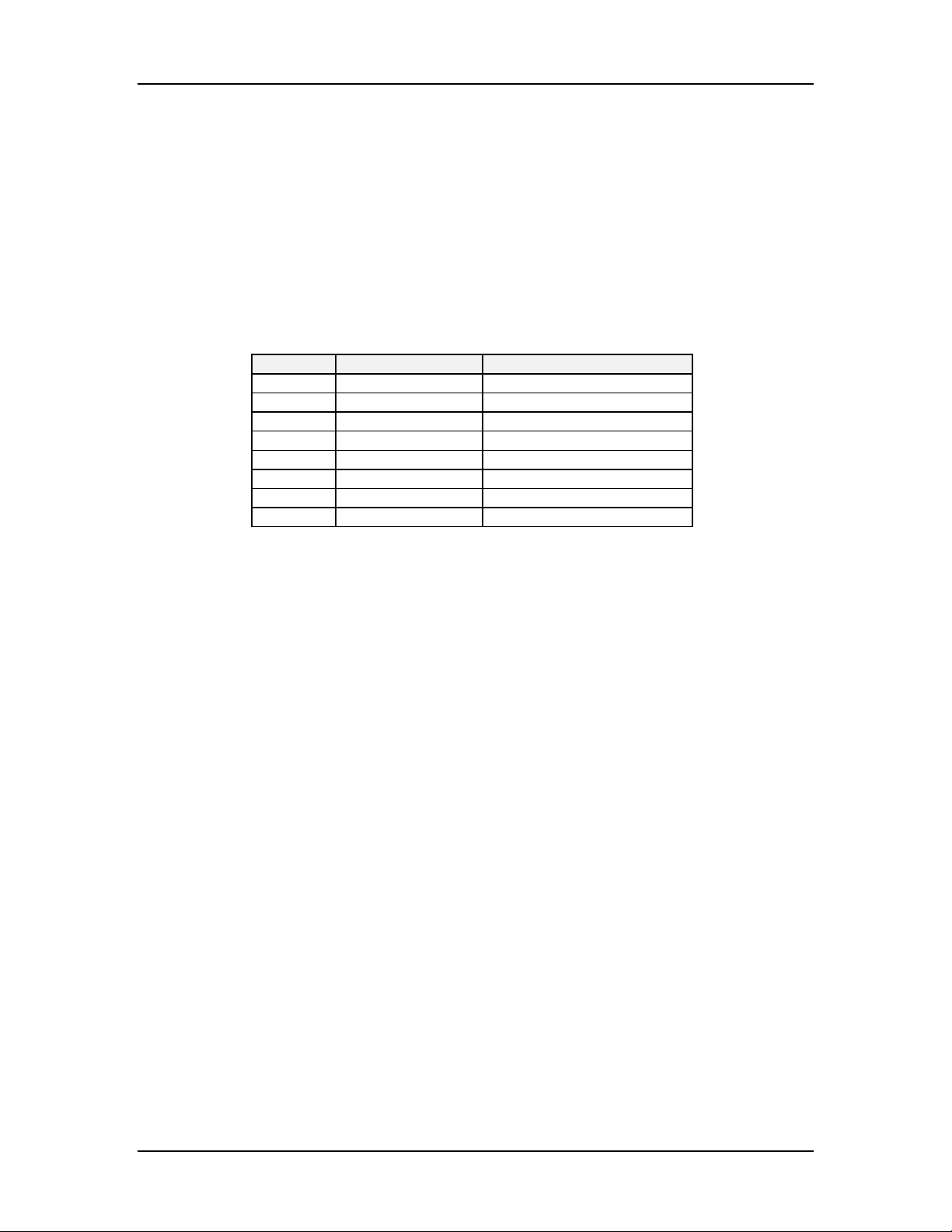
2 RS-232
The following paragraphs define the function of the serial protocols that can be selected for the
RS-232 interface.
Pin # Symbol Description
1 Chassis Ground
2 TxD Transmit Data
3 RxD Receive Data
11 & 19 RTS Request To Send
5 CTS Clear To Send
6 DSR Data Set Ready
7 Signal Ground
20 DTR (Busy) Data Terminal Ready
Figure 1 – RS-232 Pin-out
2.1 Ready/Busy
When this protocol is selected, the voltage level of the busy pin in the interface cable connector
determines whether the printer is busy or not. In this protocol the busy signal will be sent when
the serial buffer is greater than 85% full. The printer will continue to send the busy signal until
the serial buffer is less than 50% full.
2.2 Xon/Xoff
In this protocol the XOFF signals the host computer that the printer is busy when:
• The buffer is over 85% full.
• The printer is placed Offline manually.
• The printer goes Offline due to a fault.
The XOFF character (13 Hex) is transmitted to the host in response to each character received
until the serial buffer falls below 50% or the printer is placed Online. Then, an XON (11 Hex) is
transmitted to the host and the printer will accept incoming data.
In addition, there is a variation to this protocol: Robust XON.
2.2.1 Robust Xon
This parameter allows the operator to set up the XON portion of the XON/XOFF Protocol to behave in a ROBUST fashion. This protocol is the same as a normal XON/XOFF Protocol except that the XON signal is sent repeatedly until the printer starts receiving data again. In the Robust XON Protocol variation, the printer will send an XON signal every five seconds unless it receives at least one byte of data during the five second interval.
5

Line Printer Applications Manual
2.3 Block Mode Protocols
A number of protocols exist in your printer that use a Block Mode in the handling of data. In
Block Mode, data is sent in units of a predetermined size. How the printer responds is determined
by the protocol selected.
The maximum block size is 50% of the data buffer. In the shared configuration, the data buffer is
2048 bytes and, therefore, the maximum block size is 1024 bytes. In the serial configuration the
data buffer is 4096 bytes, therefore the maximum block size would be 2048 bytes.
There are six Block Mode protocols that can be selected through the printer control panel.
• Enquiry/Acknowledge (Enq/Ack)
• End of Text/Acknowledge (Etx/Ack)
• End of Text/Acknowledge/Negative Acknowledge (Etx/Ack/Nak)
• Acknowledge/Negative Acknowledge (Ack/Nak)
• XON/XOFF/End of Text/Acknowledge (Xon/off/Etx/Ack)
• XON/XOFF/Enquiry/Acknowledge (Xon/off/Enq/Ack)
2.3.1 Enq/Ack
This stands for ENQuiry/ACKnowledge. In this protocol, the HOST sends an ENQuiry to the
printer to find if it is ready to accept data. If it is ready, the printer will send the ACKnowledge
signal back to the host.
In order for the printer to be ready, it must have no faults, be Online and have sufficient space in
the buffer. If the printer is Offline, in a fault condition, or the buffer is more than 85% full, it will
not send the ACKnowledge signal to the host ENQuiry. If the printer is placed Online, any fault
conditions are cleared, and the buffer has sufficient room, the printer will respond with an
ACKnowledge signal to the ENQuiry from the host computer.
Note:
If the printer stopped sending the ACKnowledge signal because the buffer was over 85% full, it will
not begin sending the ACKnowledge signal again until the buffer is less than 50% full.
2.3.2 Etx/Ack
This protocol is the same as the ENQ/ACK except that the response initiator is the ETX (end of
text) character instead of the ENQuiry.
6

Interface Protocols
2.3.3 Etx/Ack/Nak
This protocol functions like the ETX/ACK Protocol with the addition of a NAK (Negative
ACKnowledgment) response. If the printer is ready to accept data, it will respond to an ETX
character with an ACK character
The NAK response is sent if any data errors have occurred since the previous ETX. When this
occurs, the printer will discard all data received since the last ETX. The host will then re-transmit
the erroneous data block. After three consecutive NAK responses, the printer will respond with an
ACK and print the data as well as possible.
If the printer is Offline, in a fault condition other than a data error, or the printer is busy as a
result of the data buffer being more than 85% full, the host will receive no response to the ETX.
The printer will respond with an ACK when it is placed Online and the fault is cleared, or when
the buffer falls below 50% full.
2.3.4 Ack/Nak
The ACK/NAK Protocol is identical to the ETX/ACK/NAK protocol except that the response
initiator is a carriage return. Therefore, the block size is identical to the line length.
2.3.5 Xon/off/Etx/Ack
This protocol operates exactly like the XON/XOFF protocol for buffer control, but adds the
capability of responding to an ETX character with an ACK when all data prior to the ETX has been
printed and it is ready to receive more data.
2.3.6 Xon/off/Enq/Ack
Designed for three-wire systems where the host needs to know when a print job is completed, this
protocol functions in the same manner as the Xon/off/Etx/Ack Protocol except that it responds
to the ENQ character instead of the ETX character. When the printer receives an ENQ character,
it responds by transmitting an ACK character to the host.
7

Line Printer Applications Manual
2.4 Status Enquiry
The Status Enquiry feature may be enabled in conjunction with any other protocol. When enabled
and the host sends an ENQ character, the printer responds by sending a printer status byte. The
status byte is designed to be a printable code and is the only printable code the printer can
transmit. The bit pattern is as follows:
Bit Meaning/Value
7 Parity if 7 bit data and parity enabled (MSB)
6 Always a 1
5 1 if Data Overrun
4 Always 0
3 1 if Parity Error
2 1 if Paper System Error or Platen Open
1 1 if Offline
0 1 if Busy (fault or buffer full) (LSB)
Figure 2 – Printer Status Byte
The Status Enquiry feature is slightly different when the current emulation is the HP2564C.
Instead of responding to the ENQ character, the printer will respond to the ECS ? DC1 sequence.
The bit pattern of the status response is as follows:
Bit Meaning/Value
7 Parity if 7 bit data and parity enabled (MSB)
6 Always a 0
5 Always a 1
4 Always a 1
3 0 if Parity Error, Data Overrun, or Buffer
Overflow
2 1 if Offline
1 1 if Busy (fault or buffer full)
0 1 if Paper System Error or Platen Open (LSB)
Figure 3 – Printer Status Byte – HP2564C Emulation
3 Twinax / Coax
The T6000 Series provides a combination Twinax / Coax interface card that plugs into the PSIO
slot.
The Twinax interface is based on the IBM 5250 protocol as defined in IBM document 5250
Information Display System to System/36, System/38 and Application System/400 System Units Product
Attachment Information, dated September 1990.
The Coax interface is based on the IBM 3270 protocol as defined in IBM document IBM
3174/3274 Control Unit to Device Product Attachment Information, dated November 1989.
8

Interface Protocols
4 LAN
The T6000 Series provides an Ethernet 10 /100 card that plugs in to the PSIO slot. This card is
compatible with the 10BASET and 100BASET LAN interfaces, and supports numerous protocol
stacks.
4.1 PC Network Printing
Full information on the network card, Windows and Unix printing, and printer management
functions can be found in another section of the printer CDROM, or from the TallyGenicom web
site (http://www.tallygenicom.com
4.2 Configuring Your IBM Host for Network Printing
The IBM Redbooks on AS/400 Printing (#SG24-2160 and SG24-6250) and S/390 Printing (#SG24-
6234) are excellent references for learning about network printing from IBM systems. You can
download these redbooks from the IBM Redbooks website, http://publib-
b.boulder.ibm.com/Redbooks.nsf/portals/.
The IBM Network Printer Ethernet Configuration Guide (IBM #G544-5240) provides background
information on connecting your Tally network printer to a wide variety of IBM systems and
software, including AS/400, OS/390, MVS, OS/2, and AIX.
The ideal method of network-attaching a TallyGenicom printer to an IBM Host is known as “LAN
Attachment”. This method gives the operator the greatest amount of control over the printing
process. See the appropriate “Configuring LAN Attachment” section below for more details. All
methods of LAN Attachment require specific features in the host OS and/or the printer.
When LAN Attachment is not an available option, the next best thing is to use LPR/LPD
Attachment. This method does not give the operator the printer status and fault recovery features
found in “LAN Attachment”; however, it does provide network printing capability. See the
“Configuring LPR/LPD Attachment” section below.
If the printer or host computer do not support the above methods, then you have the following
options:
1. direct-connect via Twinax or Coax interface (non-LAN connection)
2. attach printer to PC and spool files from AS/400 to PC via PC5250 transform
).
9

Line Printer Applications Manual
4.3 Configuring TallyCom+ PSIO (LANPlex-3) for IBM Host
Printing
The NIC settings may be configured by using a Web Browser (Netscape or Internet Explorer) to
access the printer's internal web page; set the browser’s URL to the printer’s IP address.
The NIC’s TCP/IP settings should reflect the following:
IP Address = a fixed address (DHCP and other dynamic addressing schemes are not
recommended).
Gateway = IP address of nearest router on this network segment.
SubNet Mask = same as used by Host computer
Share Timeout must be increased from the default setting of 20 seconds.
1. Select "Advanced Configuration", then "General".
2. At the bottom of the "General Settings" page, there are 3 Timeout values. Set the "Share"
timeout to 180 seconds.
3. Click "Save & Continue", then "Restart PrintServer" to make the new setting take effect.
4.4 Configuring IBM AS/400 LAN Attachment
The IBM Redbooks on AS/400 Printing (#SG24-2160 and SG24-6250) describe various methods of
LAN-attaching printers. LAN Attachment has job management features not available with other
methods of network printing, due to its use of bidirectional host-printer interaction. There are
four ways to do LAN Attachment:
1. IPDS
2. WSCST/PJL (OS/400 V3R7 and later)
3. PCL/PJL (OS/400 V3R7 and later)
4. SNMP (OS/400 V4R5 and later)
The LAN-attach methods are described in more detail below. All LAN-attach methods
communicate over a raw TCP port, using a protocol specific to that LAN-attach method. To use
any of these methods, you must first create a Device Description (CRTDEVPRT) and PSF
Configuration Object (CRTPSFCFG) on the AS/400.
4.4.1 IPDS LAN Attachment
IPDS attachment uses PPR/PPD protocol to utilize IPDS datastream for job control and printing.
Requires IPDS-over-Ethernet option in printer. Recommended method for all TallyGenicom
LIDM IPDS printers.
Device settings:
Device Class = *LAN
Device Type = *IPDS
Device Model = 0
LAN Attachment = *IP
Advanced Function Printing = *YES
Port Number = (NIC's raw TCP port, 9100 for LanPlex-3)
Online at IPL = *YES
Font Identifier = 11
Form Feed = *CONT (or *AUTOCUT for cut-sheet)
Activation timer = *NOMAX
Release timer = *SEC15
Remote Location = (printer’s IP address, in single quote-marks)
10

Interface Protocols
11

Line Printer Applications Manual
4.4.2 WSCST/PJL LAN Attachment
WSCST/PJL attachment uses PJL commands for job control, and Tally ANSI emulation for
printing. Requires PJL support in printer (T62xx ver 2.2+, T60xx ver 9.3+), and TallyGenicom
Workstation Customization File. Recommended method for TallyGenicom LIDM non-IPDS
printers.
First, download the Workstation Customization File (t6wscst.savf) from the TallyGenicom website,
and unSave it to your AS/400. Then create the Workstation Customization File (CRTWSCST) in
the QGPL Library.
Device settings:
Device Class = *LAN
Device Type = 3812
Device Model = 1
LAN Attachment = *IP
Port Number = (NIC's raw TCP port, 9100 for LanPlex-3)
Online at IPL = *YES
Font Identifier = 11
Form Feed = *CONT (or *AUTOCUT for cut-sheet)
Activation timer = *NOMAX
Release timer = *SEC15
Host print transform = *YES
Manufacturer type and model = *WSCST
Workstation customizing object = MT660; Library = QGPL
Remote location = (printer's IP address, in single quote-marks)
System driver program = *HPPJLDRV
4.4.3 PCL/PJL LAN Attachment
PCL/PJL attachment uses PJL commands for job control, and PCL for printing. Requires
PCL4/PCL5 + PJL support in printer. Recommended method for all TallyGenicom cut-sheet and
continuous-form laser printers.
Device settings:
Device Class = *LAN
Device Type = 3812
Device Model = 1
LAN Attachment = *IP
Port Number = (NIC's raw TCP port, 9100 for LanPlex-3)
Online at IPL = *YES
Font Identifier = 11
Form Feed = *CONT (or *AUTOCUT for cut-sheet)
Activation timer = *NOMAX
Release timer = *SEC15
Host print transform = *YES
Manufacturer type and model = (*HPLJ4, *HPLJ4SI, or whichever most closely matches
the printer's PCL emulation)
Remote location = (printer's IP address, in single quote-marks)
System driver program = *HPPJLDRV
12

Interface Protocols
4.4.4 SNMP LAN Attachment
SNMP attachment uses SNMP for job control, and PCL or Proprinter emulation for printing.
Requires SNMP in NIC; NIC must support Host Resource MIB (RFC 1514), and ideally also the
Printer MIB (RFC 1759). Requires a recent version of OS/400. Works with TallyGenicom
LIDM/SIDM printers equipped with TallyCom+.
Device settings:
Device Class = *LAN
Device Type = 3812
Device Model = 1
LAN Attachment = *IP
Port Number = 161
Online at IPL = *YES
Font Identifier = 11
Form Feed = *CONT (or *AUTOCUT for cut-sheet)
Activation timer = *NOMAX
Inactivity timer = *SEC15
Host print transform = *YES
Manufacturer type and model = (*HPLJ4 for PCL printers, *IBM6400EP for LIDM
printers in EpsonFX emulation, *EPSONLQ2550 for SIDM printers in Epson LQ2550
emulation)
Workstation customizing object = *NONE
Remote location = (printer's IP address, in single quote-marks)
User-defined options = *IBMSHRCNN
System driver program = *IBMSNMPDRV
13

Line Printer Applications Manual
4.5 Configuring IBM AS/400 LPR/LPD Attachment
The IBM Redbooks on AS/400 Printing (#SG24-2160 and SG24-6250) describe the method of
attaching printers using LPR/LPD. Because LPR/LPD is a one-way protocol, it does not support
the job management features found in LAN Attachment. Basic LPR/LPD printing is done via a
Remote Output Queue, which does not use the host’s native mode spooler/writer. However, the
addition of an LPR/LPD driver gives the user a more “direct” connection, integrating the Remote
Output Queue with the spooler/writer system.
4.5.1 LPR/LPD Driver Configuration
To use the native-mode spooler/writer with a Remote Output Queue, install the IBM TSPLPRD
exit driver. Recommended method for all network-attached TallyGenicom SIDM printers, and for
TallyGenicom LIDM printers with older non-PJL firmware.
To install the TSPLPRD driver, follow the “TSPLPRD Driver”
device description as follows.
Device settings:
Device Description = (your device name)
Device Class = *LAN
Device Type = 3812
Device Model = 1
LAN Attachment = *USRDFN
Port Number = (NIC's raw TCP port, 9100 for LanPlex-3)
Physical attachment = *DIRECT
Online at IPL = *YES
Font Identifier = 11
Form Feed = *CONT
Printer error message = *INFO
Activation timer = 170
Inactivity timer = *NOMAX
Release timer = *SEC15
Host print transform = *YES
Manufacturer type and model = (*IBM6400 for LIDM printers in IBMPro emulation,
*IBM42082 for SIDM printers in IBMPro emulation)
Workstation customizing object = *NONE
Remote location = (printer's IP address, in single quote-marks)
System driver program = TSPLPRD; Library = QGPL
After generating the Device Description file, enter the following command at the prompt:
“SETRMTPQ <device name> RMTPRTQ <device name>” press ENTER.
Then VARY ON the printer, start the WRITER and you’re ready to print.
instructions. Then setup a printer
14

Interface Protocols
4.5.2 Remote Output Queue Configuration
If you do not wish to install the LPR/LPD driver, you may use the Remote Output Queue alone.
The Remote Output Queue method uses the LPR/LPD protocol on TCP Port 515 for job control
and printing.
If this method is to be used, set up the Output Queue by typing the command “CRTOUTQ” and
pressing “F4”.
Queue settings:
Output Queue = (name of queue to use for printer)
Library = *QUSRSYS
Order of File on Queue = *FIFO
Remote System = *INTNETADR
Remote Printer Queue = ‘LPDPRT1’
Once the above selections have been made, press “F10” to configure more parameters.
Go to the “Writers” line and type 1 to start the “Writer”.
Connection Type = *IP
Destination Type = *OTHER if printer is offsite from the Host; select OS400 if printer and
Host are connected on the same network segment.
Host Print Transform = *YES
Manufacturer Type and Model = (*IBM6400 for LIDM printers in IBMPro emulation,
*IBM42082 for SIDM printers in IBMPro emulation)
Internet Address = (printer’s IP address)
15

Line Printer Applications Manual
4.6 Configuring IBM S/390 LAN Attachment
1. See Chapter 11 of the Network Printer Configuration Guide (IBM #G544-5240A), about
attaching a TallyGenicom IPDS-Ethernet printer. Pay close attention to the instructions under
"Configuring Network Printers as PSF TCP/IP-Attached Physical Printers".
2. PSF (Print Services Facility, IBM #G544-5625) is the native printer driver for OS/390, and MVS.
It controls AFP (IPDS) printers that are attached via Coax or Ethernet, and works with the JES
spooler. The TallyGenicom printer must be defined in PSF as a TCP/IP-attached IPDS printer.
See the “PSF Startup”
3. InfoPrint Server / Infoprint Manager (see Redbook #SG24-6234) is an optional feature of
OS/390 and AIX software that consolidates print jobs from many different types of servers and
applications onto a single central OS/390 print server. InfoPrint Server does this by integrating
various components:
PSF (to drive Coax- or Ethernet-attached IPDS printers);
IP Printway (IBM #S544-5379) (to drive Ethernet-attached printers via LPR/LPD, IPP, or
direct socket printing);
NetSpool (to redirect VTAM data to JES spool for network printing);
InfoPrint Server Transforms (to convert output formats: AFP to PCL/Postscript, or
PCL/Postscript/PDF/SAP to AFP).
Once a printer has been defined in PSF or IP Printway, jobs may be printed to it via the InfoPrint
Server Print Interface.
4. VPS (VTAM Printer Support) from LRS (Levi Ray & Shoup) is a third-party package widely used
for printing legacy applications on TCP/IP-Attached printers. It can be used in place of PSF, and
supports printing to both Coax and Ethernet-attached printers. It accepts VTAM print data and
routes output from the JES spool to any TCP/IP-attached printer, performing data conversions as
needed.
With VPS, you can convert your print data to the type of output datastream supported by your
printers. VPS/PCL converts AFP data to PCL; VPS/IPDS converts AFP data to IPDS.
If you are printing line data or other text applications, you can use VPS/PCL and apply
simple EBCDIC-to-ASCII conversion to print these applications on your TCP/IP-attached
TallyGenicom line or serial-matrix printer.
If you are printing complex or graphic applications, you can choose either VPS/PCL for
output to laser printers, or choose VPS/IPDS for output to a TallyGenicom line printer
equipped with IPDS-Ethernet.
The “VPS Config”
instructions for configuration details.
file example shows how to configure VPS for line data applications.
16

Interface Protocols
4.7 IBM Host Connectivity Examples
4.7.1 TSPLPRD LPR Print Driver Exit Program
Product: Operating System/400 - OS/400 PRINT/SPOOL (5716SS1SP);
Operating System/400 - OS/400 PRINT/SPOOL (5763SS1SP); Operating System/400 - OS/400
PRINT/SPOOL (5769SS1SP)
Release: V4R1M0; V4R2M0; V4R3M0; V4R4M0
The TSPLPRD print driver exit program provides the function of sending spooled files from an
output queue to an ASCII printer which is attached to an LPD server. This is a similar function to
what is provided using remote output queues in OS/400, but differs because this driver exit
program is specified on a printer device description. Thus, it can make use of information
specified about the printer in the device description which is not available on a remote output
queue. Also, because it uses LPR within a printer writer, it supports page ranges yet can be used
with any printer that currently uses a remote output queue—including dot matrix and line
printers.
This exit program also serves the purpose of providing an example of a Print Driver Exit, as it is
written to the Print Driver Exit interface as documented in the AS/400 System API Reference
manual.
This exit program was introduced in the R440 version of QUSRTOOL, but will work with R410 and
later versions of OS/400. This tool is supplied as is without support. Therefore, any assistance
with configuring or using a printer device description that uses an LPR print driver exit program
must be done through Consult Line/400.
There are three ways to get the TSPLPRD utility on your iSeries 400 system:
1) Detach or download the PRTDRVXT.SAVF file from this document, upload it to an
OS/400 save file using an FTP session, and restore the objects from the save file.
2) Get the source code from the QUSRTOOL library on an R440 or later OS/400, and
compile the source code using the ILE C/400 compiler (ILE C/400 is product 5769CX2
in R4xx and product 5716CX2 in R370).
3) Call the Rochester Support Center at 800-237-5511 and ask about opening a Consult Line
PMR in order to do a remote sign on, then have the PRTDRVXT save file sent to you.
17

Line Printer Applications Manual
Getting the LPR Print Driver Exit Program (TSPLPRD) Utility From the Attached Save File
In order to restore the TSPLPRD utility from the attached save file, you will need to create a save
file on OS/400, detach the save file from this document, upload the file to OS/400 using FTP from
an MS-DOS prompt and then restore the objects. The resulting PRTDRVXT save file contains the
following objects:
--------------+--------------+--------------+--------------+-----------|
Object |Type |Attribute |Owner |Size |
--------------+--------------+--------------+--------------+-----------|
TSPLPRCP |*PGM |CLP |QDFTOWN |32768 |
--------------+--------------+--------------+--------------+-----------|
TSPLPRD |*PGM |CLE |QDFTOWN |421888 |
--------------+--------------+--------------+--------------+-----------|
TSPLPRD |*MODULE |CLE |QDFTOWN |405504 |
--------------+--------------+--------------+--------------+-----------|
TSPLPRDD |*PGM |CLP |QDFTOWN |32768 |
--------------+--------------+--------------+--------------+-----------|
SETRMTPQ |*CMD | |QDFTOWN |4096 |
--------------+--------------+--------------+--------------+-----------|
QATTCL |*FILE |PF |QDFTOWN |69632 |
--------------+--------------+--------------+--------------+-----------|
QATTCMD |*FILE |PF |QDFTOWN |16384 |
--------------+--------------+--------------+--------------+-----------|
QATTINFO |*FILE |PF |QDFTOWN |28672 |
--------------+--------------+--------------+--------------+-----------|
QATTSYSC |*FILE |PF |QDFTOWN |933888 |
--------------+--------------+--------------+--------------+-----------|
Additionally, the above source physical files contain the following members:
------------+----------+------+----------------------------------------|
File |Member |Type |Text |
------------+----------+------+----------------------------------------|
QATTCL |TSPLPRCP |CLP |Set Remote Print Queue |
------------+----------+------+----------------------------------------|
QATTCL |TSPLPRDC |CLP |Create LPR Print Drive and associated |
| | |objects |
------------+----------+------+----------------------------------------|
QATTCL |TSPLPRDD |CLP |Delete LPR Print Drive and associated |
| | |objects |
------------+----------+------+----------------------------------------|
QATTCMD |TSPLPRSQ |CMD |Command Source for TSPLPRD tool |
------------+----------+------+----------------------------------------|
QATTINFO |TSPLPRDI |TXT |LPR Print Driver Exit Program |
------------+----------+------+----------------------------------------|
QATTSYSC |TSPLPRD |C |LPR Print Driver Exit Program |
------------+----------+------+----------------------------------------|
The first step is to create a save file called PRTDRVXT using the following command:
CRTSAVF FILE(QGPL/PRTDRVXT) TEXT(‘Save File for LPR Print Driver’)
18

Interface Protocols
Next, detach/download the PRTDRVXT.SAVF file from this document and save it in a folder on
your PC. Once the PRTDRVXT.SAVF file is on your PC, you can upload it to the iSeries 400 system
using FTP as follows:
1) Bring up an MS-DOS Prompt.
2) Use the CD command to connect to the folder that contains the
PRTDRVXT.SAVF file (for example, type CD C:\Temp if the
PRTDRVXT.SAVF file was saved in the Temp folder).
3) Type FTP <as400-system-name> in order to start an FTP session to OS/400. Sign
on using your OS/400 user profile and password.
4) Type BIN at the FTP prompt to force the data transmission to binary data.
5) Type CD QGPL at the FTP prompt to connect to the QGPL library in OS/400.
6) Type SEND PRTDRVXT.SAVF PRTDRVXT at the FTP prompt to send the
PRTDRVXT.SAVF file from the PC to the PRTDRVXT save file in OS/400.
7) Type QUIT to end the FTP session.
8) Type EXIT to close the MS-DOS Prompt.
9) Use the DSPSAVF FILE(QGPL/PRTDRVXT) command on a OS/400 command
line to verify that the file has been uploaded to OS/400 successfully. If
unsuccessful, repeat steps 1 through 8 above.
Once the PRTDRVXT.SAVF file has been successfully uploaded to the PRTDRVXT save file
OS/400, you can restore the objects from the PRTDRVXT save file to the QGPL library using the
following commands:
RSTOBJ OBJ(*ALL) SAVLIB(QGPL) DEV(*SAVF) OBJTYPE(*ALL) +
SAVF(QGPL/PRTDRVXT) RSTLIB(QGPL)
Getting the LPR Print Driver Exit Program (TSPLPRD) Utility From the QUSRTOOL Library
The source code for the LPR Print Driver utility is in member TSPLPRD in the QATTSYSC file
(which is available in the R440 version of the QUSRTOOL library) and instructions for compiling
the source code are in member TSPLPRDI in the QATTINFO file (which is also available in the
R440 version of the QUSRTOOL library).
Limitations of the LPR Print Driver Exit Program (TSPLPRD) Utility
The TSPLPRD exit program uses several APIs that access the spooled files being sent. Because of
this, it must have sufficient authority to the output queue that the spooled file is on, the library that
the output queue is in, the device description of the printer to be printed on, and the spooled file
itself. See the System API Reference manual under the QSPOPNSP API for the level of authority
needed. One possible way of insuring this exit program has authority to process all spooled files is
to use the CHGPGM CL command to change the program to adopt its owners authority and
change the owner of the program to be a user profile which has sufficient authority, such as QSYS.
19

Line Printer Applications Manual
Configuring a Printer Device Description to Use the LPR Print Driver Exit Program (TSPLPRD)
Utility
Once the TSPLPRD program and the SETRMTPQ command have been restored from the
PRTDRVXT save file or created from the files in the QUSRTOOL library, you can create a printer
device description that uses the LPR print driver exit program for any printers that you have on
your LAN/WAN. This is similar to creating a *LAN 3812 PJL device description, but has some
distinct differences as well. The major differences are that the LAN attachment (LANATTACH) is
set to *USRDFN instead of *IP and the user driver program (USRDRVPDM) parameter is used
instead of the system driver program (SYSDRVPGM) parameter on the Create Device Description
(Printer) (CRTDEVPRT ) command:
CRTDEVPRT DEVD(printer-device-name) DEVCLS(*LAN) TYPE(3812) + MODEL(1)
LANATTACH(*USRDFN) PORT(0) FONT(11) FORMFEED(*CONT) + PRTERRMSG(*INFO)
INACTTMR(*SEC15) TRANSFORM(*YES) + MFRTYPMDL(*IBM42023)
RMTLOCNAME(printer-ip-address) + USRDRVPGM(QGPL/TSPLPRD) WSCST(*NONE)
In order to use this driver on a printer device, the USRDFNDTA of the printer device description
needs to be set to a special value which the driver looks for. The required format for that special
value is RMTPRTQ (‘remote-printer-queue-name-and-path’). The value remote-printer-queuename-and-path must not exceed 255 bytes in length. This value corresponds to the remote printer
queue name that would normally be specified on a remote output queue (RMTOUTQ) for that
same printer. For instance, for the IBM Network Printers, this value would be ‘PASS’. In order to
set this special value into the device description USRDFNDTA parameter, the user can use the
SETRMTPQ command created as part of this tool. The format of the command is:
SETRMTPQ DEVD(printer-device-name) RMTPRTQ(remote-printer-queue-name)
where ‘remote-printer-queue-name-and-path’ is the name and path of the remote printer queue
within that device. If you are currently using a remote output queue (RMTOUTQ) for a particular
printer, you can use the Remote Printer Queue (RMTPRTQ) value your RMTOUTQ in the
SETRMTPQ command. Otherwise, you can refer to the following document for a list of
recommended values for the Remote Printer Queue (RMTPRTQ) parameter:
(Document link: Database ‘AS400 Support Line KnowledgeBase’, View ‘Print\Network Attached
Printers’, Document ‘TCP/IP LPR/LPD Printing with Recommended RMTPRTQ Values’)
8233537 Recommended Remote Printer Queue Values for Remote Output Queues (RMTOUTQs)
Note: If you receive MSGCPD0028, Library PRTDRVXT not found, when using the SETRMTPQ
command, you will need to use the following command to change the SETRMTPQ command so it
points to program TSPLPRCP in library QGPL instead of library PRTDRVXT:
CHGCMD CMD(QGPL/SETRMTPQ) PGM(QGPL/TSPLPRCP)
In addition, if you would like to specify a particular filter for the LPR code to use, you can specify
that on the user-defined options USRDFNOPT parameter of the CRTDEVPRT or CHGDEVPRT
commands. The required format is as follows:
CHGDEVPRT DEVD(printer-device-name) USRDFNOPT(‘FILTER(x)’) where x is the filter the
user wants to use. If no filter is specified in the USRDFNOPT of the printer device, the ‘l’ filter will
be used.
20

Interface Protocols
4.7.2 PSF Startup Procedure - Recommended Settings
The TallyGenicom line printers support the same Pagedef, Formdef, and Font settings that are
used by IBM 4234 line printers. The TallyGenicom printer reports to the host that it is IBM 4234
compatible. The TallyGenicom printer also supports most IBM 6400 Pagedefs, Formdefs, and
Fonts, but some fonts will require modifying the APSCS34V/APSCP34V sections of the
APSRFTBL (Font Resource Table) to provide the needed font and codepage mapping.
Default settings should be chosen to match the paper size, font quality, line and character
spacing most commonly used. You may choose different settings for Job Separator pages and
Dataset pages (for instance, you may wish to print the Job Separator page in a compressed font).
Pagedef
For 8.5"W x 11"L (Letter Portrait) forms, use one of the following:
P1A06462, 6 lpi, 64 lines/page
P1A08584, 8 lpi, 85 lines/page
For 11"W x 8.5"L (Letter Landscape) forms, use:
P1J06484, 8 lpi, 64 lines/page
For 14.88"W x 11"L (Wide Fanfold) forms, use one of the following:
P1L06464, 6 lpi, 64 lines/page
P1L08584, 8 lpi, 85 lines/page
Formdef
We recommend that you use one of the following Formdefs to control font quality. These are
newer Formdefs designed specifically for the IBM 6400 and similar printers.
F1Q10010 = Draft quality
F1Q50010 = DP quality
F1QA0010 = NLQ quality
If your system does not have these Formdefs, an alternative Formdef is:
F1A00010 = no duplex, bin #1, no starting offset.
Font
We recommend that you select one of the following printer-resident fonts. You may use different
fonts for Job Separator and Dataset pages, if you like:
X0GT10 = Gothic 10 cpi, DCF Rel 2 Code Page (1002)
X0GT12 = Gothic 12 cpi, DCF Rel 2 Code Page (1002)
X0GT15 = Gothic 15 cpi, DCF Rel 2 Code Page (1002)
We have encoded the recommended settings for Letter Portrait printing of "standard reports" in
the attached PSF Startup file below. You may use that as a starting point. Remember that within
the JES spool itself, you may override the above PSF defaults for any print job by specifying a
different FCB (Pagedef), UCS (Font), or FORMS parameter with the $T,PRTxx command.
21

Line Printer Applications Manual
IBM PSF Startup Procedure for a TallyGenicom T6xxx TCP/IP-attached IPDS printer:
================================================================================
//AOPU1004 JOB MSGLEVEL=1 STC08520
//PSFU1004 EXEC AOPU1004
XXAOPU1004 PROC
XX***** THE PSF LINE-PRINTER WRITER PROCEDURE ***************
XX*
XX*01* MODULE-NAME = APSWPROR
XX* $MOD(APSWPROR) COMP(APS) PROD(PSF) : RELEASE 3.2.0
XX*
XX*01* DESCRIPTIVE-NAME = START PROCEDURE FOR PSF:
XX*
XX* TCP/IP ATTACHED DEVICES
XX*
XX*01* STATUS = VERSION 3, RELEASE 2, LEVEL 0
XX*
XX*01* FUNCTION = SET PSF OPTIONS AND RESOURCES. @DUC
XX*
XX*01* NOTES =
XX* THE FULL NAME OF THE DEFAULT PAGEDEF IS P1A06462.
XX* THE FULL NAME OF THE DEFAULT FORMDEF IS F1Q50010.
XX* THE FULL NAME OF THE DEFAULT CORE FONT IS X0GT15.
XX* THE FULL NAME OF EQUIVALENT COMPATIBILITY FONT IS X0GT15.
XX*
XX* THE FULL NAME OF THE SEPARATOR PAGE PAGEDEF IS P1A06462.
XX* THE FULL NAME OF THE SEPARATOR PAGE CORE FONT IS X0GT15.
XX* THE FULL NAME OF EQUIVALENT COMPATIBILITY FONT IS X0GT15.
XX*
XX* REQUIRED ACTIONS =
XX* RESOLUTION - THIS START PROCEDURE IS SET UP FOR DRIVING
XX* A TCP/IP-ATTACHED IBM 6400 OR TALLY T6050 PRINTER.
XX*
XX* A) SIMPLEX/DUPLEX - THIS START PROCEDURE IS SET UP TO
XX* DEFAULT TO SIMPLEX PRINTING.
XX*
XX* B) ATTACHMENT - THIS START PROCEDURE IS SET UP FOR A TCP/IP
XX* ATTACHED PRINTER. TO CHANGE IT TO SNA OR CHANNEL:
XX* - UNCOMMENT AND MODIFY THE STATEMENTS INDICATED.
XX* - If your TCP/IP start procedure is not named 'TCPIP',
XX* then change the PARM definition on the EXEC statement.
XX*
XX**** END OF SPECIFICATIONS ***/
XX*
XXSTEP01 EXEC PGM=APSPPIEP,REGION=4096K,TIME=1440,PARM=(,,,,TCPIP)
XXSTEPLIB DD DISP=SHR,DSN=SYS1.DS.LINKLIB
XXJOBHDR OUTPUT PAGEDEF=A06462, /* JOB SEPARATOR PAGEDEF */
XX FORMDEF=Q50010,CHARS=GT15 /* JOB SEPARATOR FORMDEF @00C*/
XXJOBTLR OUTPUT PAGEDEF=A06462, /* JOB SEPARATOR PAGEDEF */
XX FORMDEF=Q50010,CHARS=GT15 /* JOB SEPARATOR FORMDEF @00C*/
XXDSHDR OUTPUT PAGEDEF=A06462, /* DS SEPARATOR PAGEDEF */
XX FORMDEF=Q50010,CHARS=GT15 /* DS SEPARATOR FORMDEF @00C*/
XXMSGDS OUTPUT PAGEDEF=A06462, /* MESSAGE DATASET PAGEDEF */
XX FORMDEF=Q50010 /* MESSAGE DATASET FORMDEF */
XX*
XXFONT01 DD DSN=SYS1.FONTLIBB,DISP=SHR /* SYSTEM 240 PEL FONTS */
XX DD DSN=SYS1.FONTOLN,DISP=SHR /* SYSTEM OUTLINE FONTS */
XX DD DSN=DS.PERM.FONTLIB,DISP=SHR /* USER FONTS */
XXFONT02 DD DSN=SYS1.FONT300,DISP=SHR /* SYSTEM 300 PEL FONTS */
XX DD DSN=SYS1.FONTOLN,DISP=SHR /* SYSTEM OUTLINE FONTS */
XX DD DSN=DS.PERM.FONTLIB,DISP=SHR /* USER FONTS */
XX*
XXPSEG01 DD DSN=DS.PERM.AFPLIB,DISP=SHR
XX*SEG01 DD DSN=INST.PSEGLIB,DISP=SHR /* INSTALLATION PAGE SEGMENTS */
XX* FOR 240 PEL PRINTERS
22

Interface Protocols
XX* DD DSN=SPEC.PSEGLIB,DISP=SHR /* SPECIAL PAGE SEGMENTS */
XX*
XXPSEG02 DD DSN=DS.PERM.AFPLIB,DISP=SHR
XX*SEG02 DD DSN=INST.PSEGLIB,DISP=SHR /* INSTALLATION PAGE SEGMENTS */
XX* FOR 300 PEL PRINTERS
XX*
XXOLAY01 DD DSN=DS.PERM.AFPLIB,DISP=SHR
XX*LAY01 DD DSN=INST.OVERLIB,DISP=SHR /* INSTALLATION OVERLAYS */
XX* FOR 240 PEL PRINTERS
XX*
XXOLAY02 DD DSN=DS.PERM.AFPLIB,DISP=SHR
XX*LAY02 DD DSN=INST.OVERLIB,DISP=SHR /* INSTALLATION OVERLAYS */
XX* FOR 300 PEL PRINTERS
XX*
XXPDEF01 DD DSN=SYS1.PDEFLIB,DISP=SHR /* SYSTEM PAGE DEFINITIONS */
XX* DD DSN=INST.PDEFLIB,DISP=SHR /* INSTALLATION PAGE DEFS */
XX*
XXFDEF01 DD DSN=SYS1.FDEFLIB,DISP=SHR /* SYSTEM FORM DEFINITIONS */
XX* DD DSN=INST.FDEFLIB,DISP=SHR /* INSTALLATION FORM DEFS */
XX*
XX* *********************************************************** */
XX* PRINTDEV */
XX* *********************************************************** */
XXPRT1004 CNTL
XXPRT1004 PRINTDEV FONTDD=*.FONT01, /* DEFAULT FONT LIBRARY DD */
XX FONT240=*.FONT01, /* 240 PEL FONT LIBRARY DD */
XX FONT300=*.FONT02, /* 300 PEL FONT LIBRARY DD */
XX OVLYDD=*.OLAY01, /* DEFAULT OVERLAY LIBRARY DD */
XX OVLY240=*.OLAY01, /* 240 PEL OVERLAY LIBRARY DD */
XX OVLY300=*.OLAY02, /* 300 PEL OVERLAY LIBRARY DD */
XX PSEGDD=*.PSEG01, /* DEFAULT SEGMENT LIBRARY DD */
XX PSEG240=*.PSEG01, /* 240 PEL SEGMENT LIBRARY DD */
XX PSEG300=*.PSEG02, /* 300 PEL SEGMENT LIBRARY DD */
XX PDEFDD=*.PDEF01, /* PAGEDEF LIBRARY DD */
XX FDEFDD=*.FDEF01, /* FORMDEF LIBRARY DD */
XX JOBHDR=*.JOBHDR, /* JOB HEADER SEPARATOR OUTPUT */
XX JOBTRLR=*.JOBTLR, /* JOB TRAILER SEPARATOR OUTPUT */
XX DSHDR=*.DSHDR, /* DATA SET HEADER SEPARATOR */
XX MESSAGE=*.MSGDS, /* MESSAGE DATA SET OUTPUT */
XX PAGEDEF=A06462, /* DEVICE PAGEDEF DEFAULT */
XX FORMDEF=Q50010, /* DEFAULT FORMDEF - SIMPLEX */
XX CHARS=(GT15), /* DEVICE DEFAULT FONT @00C*/
XX PIMSG=(YES,16), /* ACCUMULATE DATA SET MESSAGES */
XX DATACK=BLOCK, /* REPORT ALL DATA-CHECK ERRORS */
XX TRACE=YES, /* CREATE INTERNAL TRACE */
XX FAILURE=WCONNECT, /* ACTION ON PRINTER FAILURE */
XX TIMEOUT=REDRIVE, /* PSF ACTION ON TIMEOUT */
XX MGMTMODE=IMMED,
XX DISCINTV=1800, /* DISCONNECT INTERVAL, SECONDS */
XX CONNINTV=1800, /* CONNECT INTERVAL, SECONDS */
XX IPADDR='172.31.208.242', /* IP ADDRESS FOR TCP/IP */
XX PORTNO=5001 /* TCP PORT FOR IPDS */
XXPRT1004 ENDCNTL
23

Line Printer Applications Manual
4.7.3 VPS Configuration File for a TallyGenicom TCP/IP-attached
printer:
*======================================================================*
* *
* VPSDEFLT VPS RELEASE 8.0 PRINTER MASTER DEFAULT MEMBER *
* *
*======================================================================*
* Printer: TallyGenicom Model: Any
*----------------------------------------------------------------------*
* JES SYSOUT SELECTION CRITERIA PARAMETERS *
*----------------------------------------------------------------------*
*----------------------------------------------------------------------*
* VPS/AFP PARAMETERS *
*----------------------------------------------------------------------*
*CHARS=(GT10),
*FORM=???,
*
AFPADJ=(0,0,0,0), NO OVERLAY MARGINS OR LOGICAL PAGE OFFSETS
AUTOEJCT=(Y,Y,N,Y), PERFORM EXTRA FORM FEED
DCKACTN=UNBLOCK, REPORT ALL DATA-CHECK EXCEPTIONS
DEVTYPE=TALLY, PRINTER TYPE OR MODULE
CKPTPAGE=0,
CKPTLINE=0,
CONVTYPE=NONE, CONVERSION OPTIONS FOR AFP
FFSEQ=0D0C, FORM FEED SEQUENCE
FCB=Y, FCB SUPPORT
FORMFEED=Y,
NLSEQ=0D0A, SPECIAL NEW LINE SEQUENCE FOR PRINTER
PCLOPTS=0000, VPS/PCL CLEAR THE PRINTER OF ALL DATASETS
RELREQ=I,
*
COMMTYPE=(TCPIP,LPD), VPS LPR/LPD CONNECTION
TCPHOST=10.224.110.184, IP PRINTER ADDRESS
TCPRPORT=515, TCP PORT NUMBER (LPR/LPD SELECTED)
TCPPRTR=lpdprt1,
TCPMRD=00, TIMEOUT CONNECTION ("NOT ZERO"=EDRAINED)
TCPOPTS=08200000, SEND FORM FEED SEQUENCE AT END OF DATASET
*TCPOPTS=20000000, SEND FORM FEED SEQUENCE AT END OF DATASET
*----------------------------------------------------------------------*
* JES SYSOUT SELECTION CRITERIA PARAMETERS *
*----------------------------------------------------------------------*
CLASS=AJ, CLASS SELECTION LIST ==========> NO DEFAULT
DEST=RMTE9017, DESTINATION SELECTION =========> NO DEFAULT
*WRITER= SPECIAL WRITER SELECTION ======> NO DEFAULT
*----------------------------------------------------------------------*
* MICELLANEOUS PARAMETERS *
*----------------------------------------------------------------------*
GRPNAME=SDF, PRINTER GROUP NAME
*PCMDOPTS=80000000, START SEPARATOR MODULE TRANSLATED TO CHAR
PCMDACTN=(NOTRN,DEF),
PCMDSTRT=(,,&WRITER),
PCMDEND=(,),
*PCMDSTRT=(S132X66,S132X66,&WRITER),
*PCMDEND=(S132X66,S132X66),
*PCMDSEPS=,
*PCMDDSNS=,
*PCMDDSNE=,
*PCMDSEPE=,
PRTXLATE=(Y,VPSSXASC), TRANSLATION DATA
SEPAR=(B,VPSSSEPM,JOB,,,00),
*SEPINFO=,
WFWACTN=N PUT PRINTER IN IDLE STATE WHEN NO JOBS QUEUED
24

Interface Protocols
4.7.4 IPDS Fonts/Code Pages supported by TallyGenicom Line
Printers
TallyGenicom line printers implement the IBM 4234 IPDS font set. This file lists the
FGIDs (Font Global IDs) supported by the printer. Each FGID is a bitmap font (Draft,
DP, Gothic, Courier, Essay, OCR-A, or OCR-B) that prints at a specified CPI setting.
Not all FGIDs are available in each print quality setting; for instance, OCR fonts are
available only in the NLQ print quality setting.
FGID Typeface CPI Print Quality
26 (X'001A') GOTHIC 10.0 Draft/DP
87 (X'0057') GOTHIC 12.0 Draft/DP
204 (X'00CC') GOTHIC 13.3 Draft/DP/NLQ
222 (X'00DE') GOTHIC 15.0 Draft/DP
400 (X'0190') GOTHIC 16.7 Draft/DP/NLQ
258 (X'0102') GOTHIC 18.0 Draft/DP/NLQ
51 (X'0033') GOTHIC Cm 10.0 Draft/DP
74 (X'004A') GOTHIC Cm 12.0 Draft/DP
205 (X'00CD') GOTHIC Cm 13.3 Draft/DP/NLQ
232 (X'00E8') GOTHIC Cm 15.0 Draft/DP
300 (X'012C') GOTHIC Cm 16.7 Draft/DP/NLQ
259 (X'0103') GOTHIC Cm 18.0 Draft/DP/NLQ
11 (X'000B') COURIER 10.0 NLQ
85 (X'0055') COURIER 12.0 NLQ
223 (X'00DF') COURIER 15.0 NLQ
52 (X'0034') COURIER Cm 10.0 NLQ
75 (X'004B') COURIER Cm 12.0 NLQ
233 (X'00E9') COURIER Cm 15.0 NLQ
19 (X'0013') OCR-A 10.0 OCR
3 (X'0003') OCR-B 10.0 OCR
(Cm stands for Compressed)
CPGID Language
037 (X'0025') English (USA/Canada)
256 (X'0100') International #1
273 (X'0111') Austrian/German
275 (X'0113') Brazilian
277 (X'0115') Danish/Norwegian
278 (X'0116') Finnish/Swedish
280 (X'0118') Italian
281 (X'0119') Japanese/English
282 (X'011A') Portuguese
284 (X'011C') Spanish
285 (X'011D') English (U.K.)
290 (X'0122') Japanese/Katakana
297 (X'0129') French AZERTY
437 (X'01B5') PC CP437 (IBM ASCII)
500 (X'01F4') International #5
850 (X'0352') PC CP850 (Multilingual)
863 (X'035F') PC CP863 (Canadian French)
870 (X'0366') Latin #2
871 (X'0367') Icelandic
880 (X'0370') Cyrillic
892 (X'037C') OCR_A
893 (X'037D') OCR_B
905 (X'0389') Turkish CP905
1026 (X'0402') Turkish CP1026
25

Line Printer Applications Manual
255027-001A
26
 Loading...