

Page 1

2900
Operator Manual
Serial - Parallel - LAN
Operator Manual 1
Page 2

This Manual is published by TallyGenicom for use with the computer printer described herein. Translations,
reprinting or copying by any means of this manual, complete or in part, in any different form requires our
explicit approval. TallyGenicom reserves the right to revise this manual without notice, for any reason. This
includes, but is not limited to, utilization of advances in the state-of-the-art and changes in the equipment or
configuration thereof. Liability for difficulties arising from unknown or unforeseen technical limitations is
disclaimed.
FCC Statement
This equipment has been tested and found to comply with the limits for a Class A digital device, pursuant to
Part 15, Subpart B of the FCC Rules. These limits are designed to provide reasonable protection against harmful interference when the equipment is operated in a commercial environment. This equipment generates,
uses, and can radiate radio frequency energy and, if not installed and used in accordance with the instruction
manual, may cause harmful interference to radio communications. Operation of this equipment in a residential
area is likely to cause harmful interference, in which case the user will be required to correct the interference
at his own expense.
WARNING
Only trained qualified personnel may open covers or remove parts that are not explicitly shown and described
in the Operator’s Manual as being accessible to the operator.
Please Note:
Printer drivers for various operating systems are available on the Internet at our Web Page
http://www.tallygenicom.com or http://www.tallygenicom.com/worldwide or at your
TallyGenicom distributor.
ACKNOWLEDGMENTS:
“IBM” and “Proprinter” are trademarks of International Business Machines Corporation.
“Epson” is a trademark of Seiko Epson Corp.
2900 Series Operator Manual
© October 2007
All rights reserved
TallyGenicom
6020 South 190th Street
Kent, Washington 98032
2 Operator Manual
Page 3

Contents
Preface ......................................................................................................... 3–9
Introduction ............................................................................................................................... 3–9
About This Manual ................................................................................................................... 3–10
Chapter 1 .................................................................................................... 3–11
Site Preparation ........................................................................................................................ 3–11
Figure 1 - 1. Shipping Screw Locations ............................................................................ 3–12
Unpacking your printer ........................................................................................................... 3–12
Repacking ................................................................................................................................. 3–12
Removing the Shipping Hardware.......................................................................................... 3–12
Figure 1 - 3. Rear view, showing Serial, Parallel and Power Plugs .................................. 3–13
Connecting the I/O ................................................................................................................. 3–13
Interface Connections and Powering Up ............................................................................... 3–13
................................................................................................................................................... 3–13
Interface Connectors ............................................................................................................... 3–13
Powering Up ............................................................................................................................. 3–14
Figure 1 - 4. Power plug and on/off switch ..................................................................... 3–14
Figure 1 - 5. Inside the Lid ................................................................................................ 3–15
Paper System ............................................................................................................................. 3–15
Paper System Components ...................................................................................................... 3–15
Print Gap ................................................................................................................................... 3–16
Paper Tension ........................................................................................................................... 3–16
Tractors ..................................................................................................................................... 3–16
Figure 1 - 6. Left and Right Paper Tractors ..................................................................... 3–16
Installing the Ribbon Cartridge .............................................................................................. 3–17
Figure 1 - 8. Installing the Ribbon Cartridge................................................................... 3–17
Figure 1 - 7. Ribbon Cartridge .......................................................................................... 3–17
Figure 1 - 9. Ribbon Shield Panels.................................................................................... 3–18
Figure 1 - 10. Control Panel .............................................................................................. 3–19
LED Indicators ......................................................................................................................... 3–19
LCD (Liquid Crystal Display) .................................................................................................. 3–19
Control Panel Components ..................................................................................................... 3–19
Operator Manual 3
Page 4

Chapter 2 .................................................................................................... 3–21
Introduction ............................................................................................................................. 3–21
Loading Paper for Standard Printing Mode .......................................................................... 3–22
Figure 2 - 1. Inside Paper Inlet, visible when looking inside the printer cabinet. ........ 3–22
Figure 2 - 2. Paper path past the lid. ................................................................................. 3–22
Figure 2 - 4. Column Alignment Scale ............................................................................. 3–23
Figure 2 - 5. Horizontal Vernier Wheel ............................................................................. 3–23
Figure 2 - 6. Top of Form Nubbin ..................................................................................... 3–24
Print Gap Adjustment .............................................................................................................. 3–25
Gap Zone .................................................................................................................................. 3–25
Print Gap Profile Mode ............................................................................................................ 3–25
Creating a Gap Zone Profile .................................................................................................... 3–25
Using a Saved Gap Zone Profile .............................................................................................. 3–26
Fine-tuning the Automatic Print Gap Setting ........................................................................ 3–26
Set Print Gap Detect Mode to Manual .................................................................................... 3–27
Figure 2 - 7. Typical Display when Print Gap Mode is set to “Auto” ............................... 3–27
Setting Up Configurations ....................................................................................................... 3–28
Figure 2 - 8. Typical display when adjusting Print Gap .................................................... 3–28
Chapter 3 .................................................................................................... 3–29
Introduction ............................................................................................................................. 3–29
Control Panel Display .............................................................................................................. 3–29
The Display During Normal Operation.................................................................................. 3–30
Figure 3 - 1. Control Panel Display for Normal Operation ............................................ 3–30
Current State ............................................................................................................................ 3–30
Current Configuration ............................................................................................................. 3–30
Paper Weight & Hammer Impact ........................................................................................... 3–30
The Display When In A Menu ................................................................................................. 3–31
Figure 3 - 2. Control Panel Display for Menus ................................................................. 3–31
Table 3 - 1 Paper Weight & Hammer Impact Indicator ................................................... 3–31
Control Panel Key Functions ................................................................................................... 3–32
Online Key ................................................................................................................................ 3–32
LF Key (Line Feed) .................................................................................................................. 3–32
FF Key (Form Feed) ................................................................................................................. 3–32
Figure 3 - 3. Control Panel ................................................................................................. 3–32
FF Key (Form Feed) continued ............................................................................................... 3–33
TOF Key (Top of Form)........................................................................................................... 3–33
View Key .................................................................................................................................... 3–33
PRINT GAP + and - Keys .......................................................................................................... 3–33
Up and Down Arrow Keys ........................................................................................................ 3–33
Menu Key .................................................................................................................................. 3–33
Enter Key................................................................................................................................... 3–34
Clear Key ................................................................................................................................... 3–34
Clear Key continued ................................................................................................................. 3–35
4 Operator Manual
Page 5

Config Key................................................................................................................................. 3–35
Control Panel Menus ............................................................................................................... 3–36
Categories, Parameters and Selections ................................................................................... 3–36
Using Menus ............................................................................................................................. 3–36
Example: Changing Form Length Using the Menu System ................................................ 3–38
How to Print a Control Panel Selected Options Report........................................................ 3–39
Operator Menu......................................................................................................................... 3–40
Font Category ........................................................................................................................... 3–40
Ser/Par Language .................................................................................................................... 3–40
Ser/Par Character Set .............................................................................................................. 3–41
Matrix ........................................................................................................................................ 3–41
OCRA Density ........................................................................................................................... 3–41
Ser/Par Style ............................................................................................................................. 3–42
CPI (Characters Per Inch) ....................................................................................................... 3–42
Panel Language ........................................................................................................................ 3–42
OCR Standards ......................................................................................................................... 3–42
Zero ........................................................................................................................................... 3–42
Compressed 8 ........................................................................................................................... 3–42
Forms Category ........................................................................................................................ 3–43
Length (lines) ........................................................................................................................... 3–43
Length (inches)........................................................................................................................ 3–43
LPI (Lines Per Inch) ................................................................................................................ 3–43
Top Margin ............................................................................................................................... 3–43
Bottom Margin ......................................................................................................................... 3–43
Left Margin ............................................................................................................................... 3–44
Right Margin ............................................................................................................................. 3–44
Horz Adjust ............................................................................................................................... 3–44
Vert Adjust................................................................................................................................. 3–44
Print to EOF (End Of Form) ................................................................................................... 3–44
Print to EOF (End Of Form) Continued ............................................................................... 3–45
Quick Access ............................................................................................................................. 3–45
Eject Distance ........................................................................................................................... 3–45
Eject Delay ................................................................................................................................ 3–46
Impact ....................................................................................................................................... 3–46
Paper Weight ............................................................................................................................ 3–46
Fast Slew .................................................................................................................................... 3–46
Double Strike ............................................................................................................................ 3–46
RibbonMonitor ......................................................................................................................... 3–46
RibnMon Thresh ...................................................................................................................... 3–47
Perf Skip .................................................................................................................................... 3–48
Print Gap Category ................................................................................................................... 3–48
Detect ........................................................................................................................................ 3–48
Adjust......................................................................................................................................... 3–48
Reset .......................................................................................................................................... 3–49
Mode ......................................................................................................................................... 3–49
Creating a Gap Zone Profile .................................................................................................... 3–50
Operator Manual 5
Page 6

Detect Distance ......................................................................................................................... 3–50
VFU Category (Vertical Format Units) ................................................................................... 3–51
VFU Enable ............................................................................................................................... 3–51
VT Channel (Vertical Tab Channel) ....................................................................................... 3–51
Skip When ................................................................................................................................. 3–51
Config Menu ............................................................................................................................. 3–52
Printer Category ....................................................................................................................... 3–52
Powerup .................................................................................................................................... 3–52
Ser/Par Emulation ................................................................................................................... 3–52
LAN Emulation (LAN Interface only) .................................................................................... 3–52
Dump Mode .............................................................................................................................. 3–52
IO Hold ..................................................................................................................................... 3–53
Report ....................................................................................................................................... 3–53
Beeper Mode ............................................................................................................................ 3–54
Beeper Volume ......................................................................................................................... 3–54
Codes Category ......................................................................................................................... 3–55
Auto LF (Line Feed) ................................................................................................................ 3–55
Auto CR (Carriage Return) ..................................................................................................... 3–55
Line Wrap ................................................................................................................................. 3–55
Wrap Line Feed ........................................................................................................................ 3–55
Print on CR ............................................................................................................................... 3–56
Form Feed at TOF .................................................................................................................... 3–56
ESC ............................................................................................................................................ 3–56
Alt ESC (Alternate Escape)..................................................................................................... 3–56
Upper Only ............................................................................................................................... 3–56
Code 7F ..................................................................................................................................... 3–57
Print 80 - 9F Hex ...................................................................................................................... 3–57
Ignore Char .............................................................................................................................. 3–57
Sub Char From ......................................................................................................................... 3–57
Sub Char To .............................................................................................................................. 3–57
Configurations Category .......................................................................................................... 3–58
Save ............................................................................................................................................ 3–58
Load........................................................................................................................................... 3–58
Powerup Config ........................................................................................................................ 3–58
Config n Label - (where n = 1 to 10)....................................................................................... 3–58
Serial I/O Category .................................................................................................................. 3–60
Baud .......................................................................................................................................... 3–60
Data Bits .................................................................................................................................... 3–60
Stop Bits .................................................................................................................................... 3–60
Parity.......................................................................................................................................... 3–60
8th Bit ........................................................................................................................................ 3–60
Protocol ..................................................................................................................................... 3–60
Status Enquiry ........................................................................................................................... 3–61
DTR Function ........................................................................................................................... 3–61
DTR Function continued......................................................................................................... 3–62
DTR Polarity ............................................................................................................................. 3–62
6 Operator Manual
Page 7

Busy Polarity.............................................................................................................................. 3–62
RTS Function ............................................................................................................................ 3–62
Robust Xon ............................................................................................................................... 3–62
Parallel I/O Category............................................................................................................... 3–63
POPC (Print On Paper Command) ........................................................................................ 3–63
8th Bit ........................................................................................................................................ 3–63
Bi-Directional ............................................................................................................................ 3–63
Intellifilter Category ................................................................................................................. 3–64
Serial.......................................................................................................................................... 3–64
Parallel ...................................................................................................................................... 3–64
Twinax/Coax ............................................................................................................................ 3–64
LAN ........................................................................................................................................... 3–64
File Management ...................................................................................................................... 3–64
TCP/IP Menu (LAN Interface Only) ..................................................................................... 3–65
IP Addr Category ...................................................................................................................... 3–65
Gateway Category ..................................................................................................................... 3–65
Subnet Category ....................................................................................................................... 3–66
Test Menu.................................................................................................................................. 3–67
Pattern Category ....................................................................................................................... 3–67
Print ........................................................................................................................................... 3–67
Fault Override Category .......................................................................................................... 3–68
Paper Motion ............................................................................................................................ 3–68
Diag Category ........................................................................................................................... 3–68
Cal-Paper (Calibrate Paper Out)............................................................................................. 3–68
Help Menu ................................................................................................................................ 3–69
Figure 3 - 5. Control Panel Navigation............................................................................. 3–69
Appendix A: Troubleshooting ..................................................................... 3–71
Introduction ............................................................................................................................. 3–71
Messages .................................................................................................................................... 3–71
Faults ......................................................................................................................................... 3–71
Fault Correction Procedure..................................................................................................... 3–71
Table A - 1. Display Messages ............................................................................................ 3–72
Table A - 2. Paper/Printing Corrective Action ................................................................ 3–76
Operator Manual 7
Page 8

Appendix B: Specifications ......................................................................... 3–77
Industry and Agency Standards ............................................................................................... 3–77
Electro-Magnetic Emissions ..................................................................................................... 3–77
Electro-Magnetic Immunity ..................................................................................................... 3–77
Energy Conservation ................................................................................................................ 3–77
Safety ......................................................................................................................................... 3–77
Acoustic ..................................................................................................................................... 3–77
Marking ..................................................................................................................................... 3–77
Physical Configurations ........................................................................................................... 3–78
Weight ....................................................................................................................................... 3–78
Dimensions ............................................................................................................................... 3–78
Preventive Maintenance........................................................................................................... 3–78
Environment ............................................................................................................................. 3–78
Operating .................................................................................................................................. 3–78
Nonoperating ........................................................................................................................... 3–78
Safety ......................................................................................................................................... 3–78
Cooling System ......................................................................................................................... 3–79
Acoustics.................................................................................................................................... 3–79
Power Supply ............................................................................................................................ 3–79
Heat Load Contribution .......................................................................................................... 3–79
Emulations ................................................................................................................................ 3–80
Characters Per Inch.................................................................................................................. 3–80
Lines Per Inch........................................................................................................................... 3–80
Type Styles ................................................................................................................................. 3–80
Draft and Data Processing ....................................................................................................... 3–80
Gothic and Courier .................................................................................................................. 3–80
OCR–A and OCR–B ................................................................................................................. 3–80
Large Character Printing ......................................................................................................... 3–80
Standard Languages and Character Sets ................................................................................ 3–81
Nonvolatile Memory................................................................................................................. 3–82
Paper Description ..................................................................................................................... 3–82
Paper Movement Speed ........................................................................................................... 3–82
Throughput .............................................................................................................................. 3–82
8 Operator Manual
Page 9
Preface
Introduction
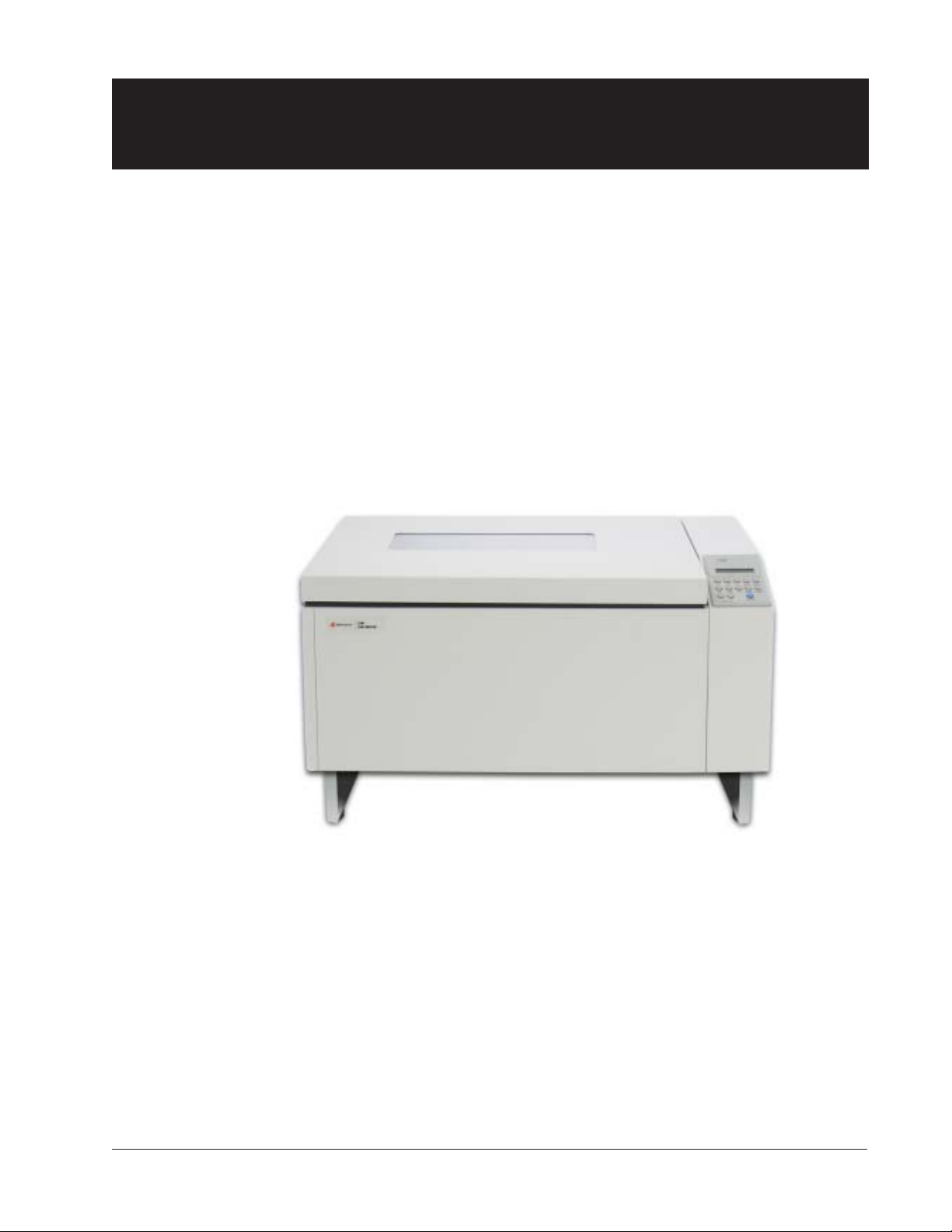
The 2900 Impact Printers are designed to handle heavy duty, high volume
workloads, with a straight paper path that provides unattended, jam-free printing of continuous forms, at high speeds. They have a wide range of printer
emulations, network printer management ability, popular graphics languages
and web administration utilities.
The 2900 Series offers the following I/O configurations (Modules):
• Standard Serial/Parallel
• LANPlex (Standard plus Ethernet 10/100 BASE-T)
In less than five minutes you can add other configurations by inserting a new
module. Installation instructions come with the module.
All interface configurations and printer
setups are performed through the control
panel on the top right of the unit. And
since the printer’s operational configuration is stored in nonvolatile memory;
you’ll never have to reconfigure your
printer because of a power loss.
Operator Manual Preface–9
Page 10

About This Manual
Conventions
We use the following conventions throughout this manual:
Text that is placed in italics draws your attention to additional helpful
information.
Sometimes your attention is more particularly drawn by the use of this
symbol.
CAREFUL!
This symbol marks information about actions
that may damage the equipment or injure the
user.
Preface–10 Operator Manual
Page 11
Chapter 1
Site Preparation
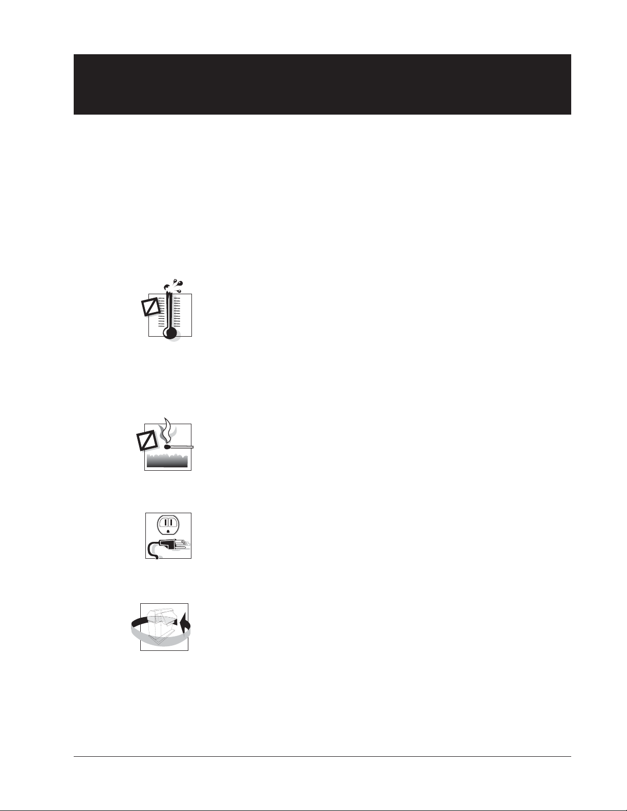
Choosing a site for your printer is important because the environment affects
your print quality. The best site for your printer is one that is protected from
dirt and heavy dust, and has a moderate temperature and humidity range. In
addition, the power source should be adequate for printer operation and
protected from power surges.
Keep the following factors in mind when choosing a printer location:
• Keep the operating environment temperature between 50°F and 104°F
• Do not locate your printer near air conditioners, open windows,
• The relative humidity should be between 10% and 90%
• The heat load contribution to the environment is 188 BTUs per hour
(10°C and 40°C).
heaters, nor in other areas where the temperature changes abruptly.
(noncondensing). Be sure to locate the printer away from any sources
of moisture, such as water faucets, refrigerators, and humidifiers.
at idle and can go as high as 2050 BTUs per hour under continuous
full-load printing conditions.
• Keep your printer away from dust, dirt, and open flames.
• Plug your printer into a grounded outlet.
• Minimum floor space recommended for your printer is 36" wide x 36"
deep (91.4 cm x 91.4 cm) to allow air movement around the printer.
Allow space to open printer doors as well. When the doors are fully
opened, the printer takes up 6.5 feet (2.0 m) of floor space.
Chapter 1: Setting Up Your Printer 1–11
Page 12
Unpacking the Printer
Unpacking your printer
Instructions for unpacking your printer are located on the outside of the
shipping container. After you have removed your printer from its container,
store the shipping materials for possible later use.
Repacking
Repacking your printer for storage or shipping is the reverse order of
unpacking. If shipping materials are needed, you can reorder them from your
dealer.
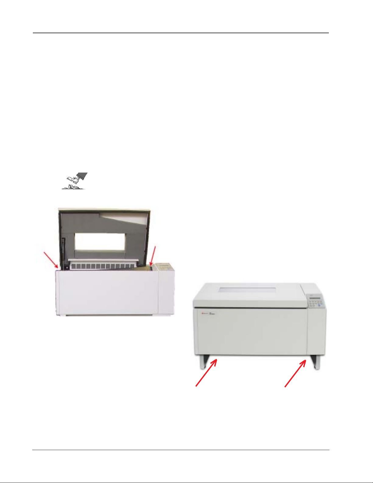
Removing the Shipping Hardware
The Shipping Hardware consists of 4 screws, identified by red tags, that secure
the printer base to the inside mechanism, and tie restraints that secure the
Paper Stacking Chains. The shipping screws fasten from underneath, 2 near the
front of the print cabinet and 2 near the rear of the cabinet.
CAREFUL!
DO NOT power up your printer before removing the shipping
hardware.
Arrows point to shipping
screw locations
1–12 Operator Manual
Figure 1 - 1. Shipping Screw Locations
Page 13
Interface Connections and Powering Up
Interface Connectors
Properly secure the cable to the printer interface using the correct connectors.
Interface Connections
CAREFUL!
Connecting the I/O
Shielded I/O cables must be used on all installations to
comply with regulatory requirements.
After connecting each interface to your printer, run a print job from the Host
Computer to verify proper function of the printer.
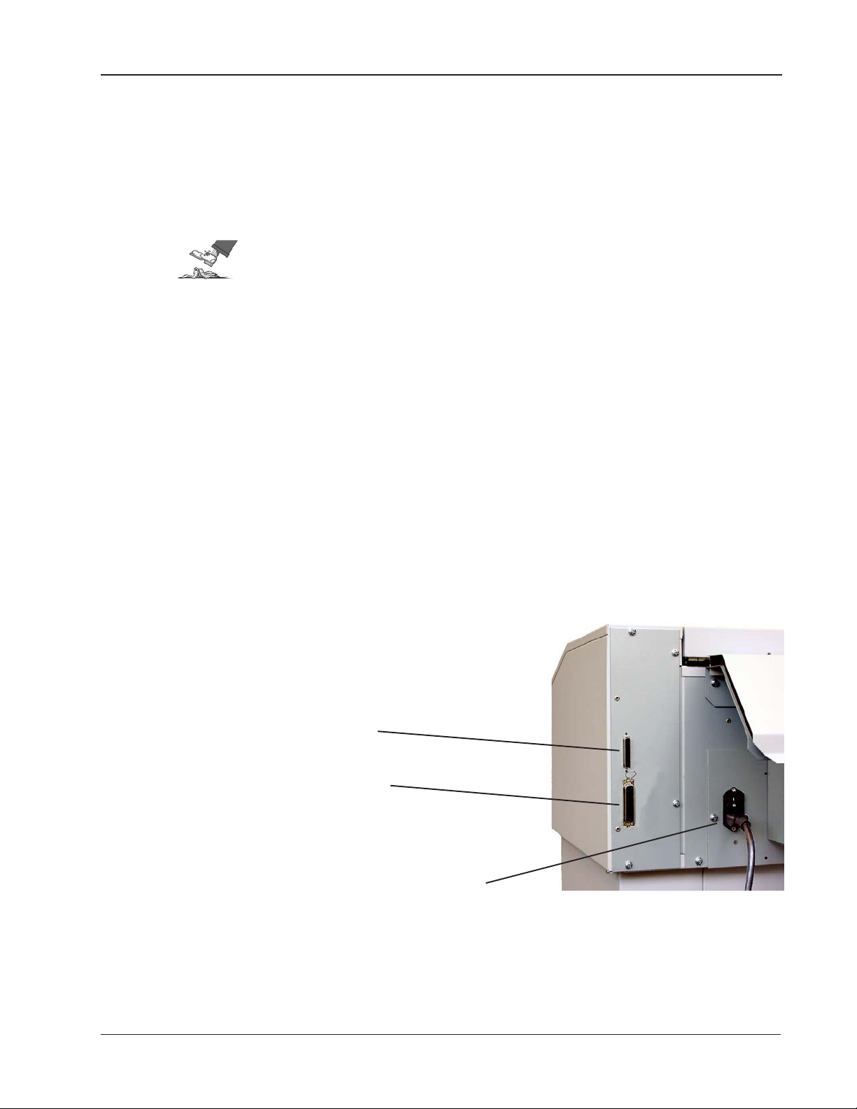
Serial/Parallel Interfaces
To connect the Serial or Parallel I/O cable, plug in the cable to the proper
connector on the I/O panel.
The serial interface operates up to 38.4 kBaud and uses a standard DB 25 serial
cable connector and standard RS-232-C signals. Serial interface cables should
be no longer than 50 feet (15.2 meters).
The Centronics parallel port is IEEE-1284 compliant and uses a 36-pin 1284-B
type connector (AMP 555119-1 or equivalent). Parallel interface cables should
be no longer than 6 feet (2 meters)
Serial Interface Port
Parallel Interface Port
Figure 1 - 3. Rear view, showing Serial, Parallel and Power Plugs
Power Plug
Chapter 1: Setting Up Your Printer 1–13
Page 14
Powering Up
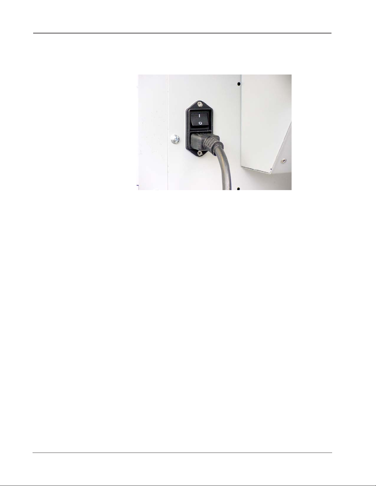
Powering Up
The power switch is located on the back of the printer, just above the 3-prong
power plug connector.
Figure 1 - 4. Power plug and on/off switch
Step 1.
Make sure the power is off by depressing the "0" side of the rocker power
switch. Connect the power cord. Plug the power cord into a proper power
outlet.
Step 2.
Turn the power on.
The printer runs a self-test each time it is powered up to check the main
processor and buffers for errors. Note that when you turn the printer on this
time, the Paper Out error displays. If any error message appears in the display,
check Appendix A for a description of the error and what actions are necessary
to clear the error.
1–14 Operator Manual
Page 15
Paper System
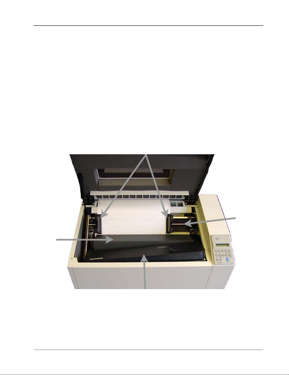
Paper System Components
The Tractors, Ribbon Cartridge, Platen and Paper Iron are all parts of the
paper system. The first two can be seen when the lid is raised. The Platen and
Paper Iron are hidden inside the housing.
Paper System Components
Tractors
Ribbon
support
platform
shaft for
tractors
Ribbon Cartridge
Figure 1 - 5. Inside the Lid
Chapter 1: Setting Up Your Printer 1–15
Page 16
Paper System Components
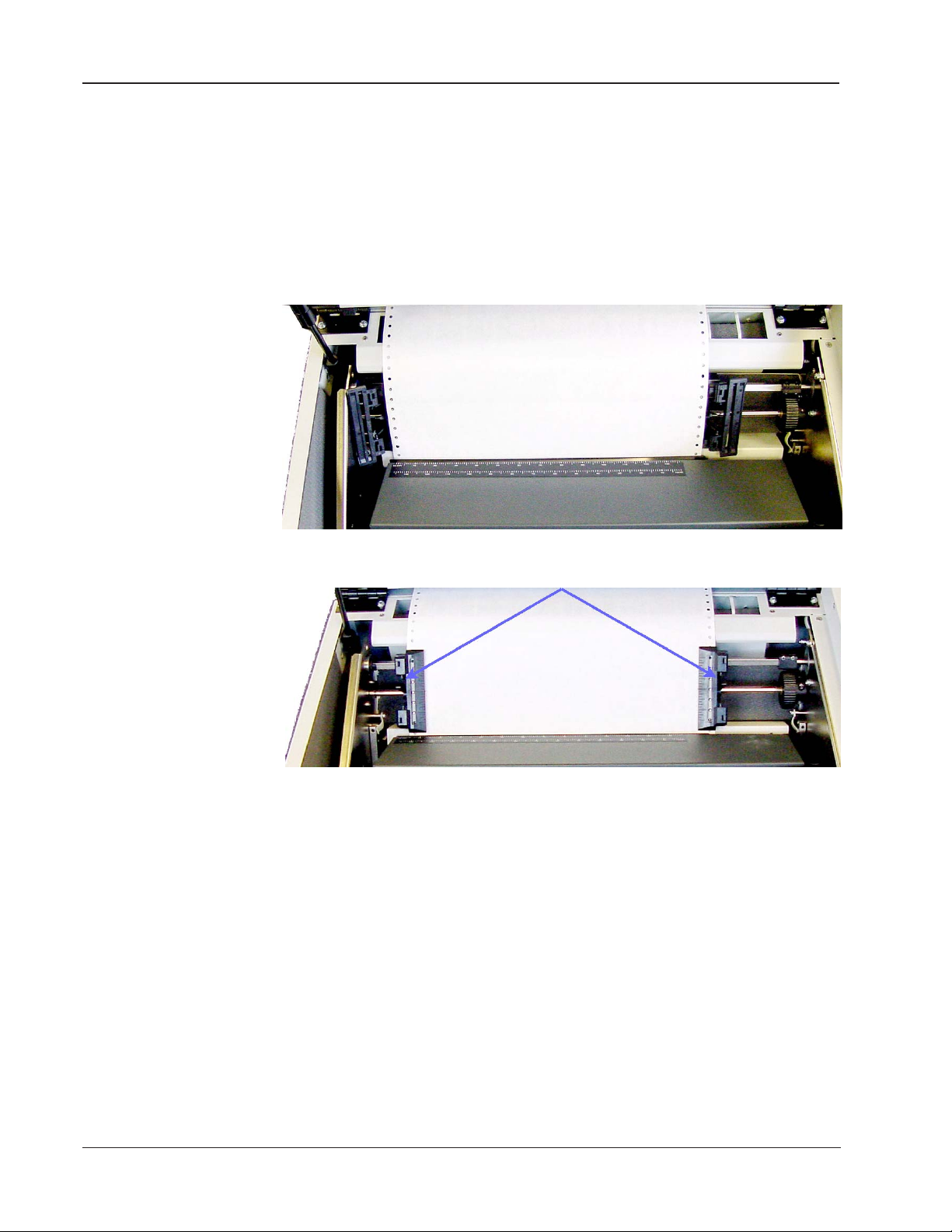
Tractors
The 2900 has two tractors to control paper movement, located on the left and
right.
A lever on each tractor keeps it locked in place on a horizontal shaft. To reposition a tractor, unlock the tractor and move it to the left or the right along the
shaft. Repositioning is generally needed only when inserting a new form or size
of paper.
Tractors
Open
Print Gap
locking
lever
Figure 1 - 6. Left and Right Paper Tractors
The 2900 printers offer Auto-Gap which simplifies operator set-up and printer
use by setting the optimum print gap based on the form thickness. The print
gap is automatically opened to its widest position when the printer is not
printing. To accommodate various thicknesses of paper, the print gap is
adjusted either automatically or manually. (See Chapter 2 pages 2-30 to 2-33
and Chapter 3 pages 3-56 to 3-58). If the Print Gap Detect Mode has been set to
"Auto," the auto gap sensing operation will take place the first time the power is
turned on, immediately after a "paper out" fault, when the TOF key is pressed,
and when printing is attempted without setting the Top Of Form. Dedicated
control panel keys also allow the print gap to be adjusted based on operator
preference.
Paper Tension
Vertical tension on the paper is pre-set. It is not controlled by the user.
1–16 Operator Manual
Page 17
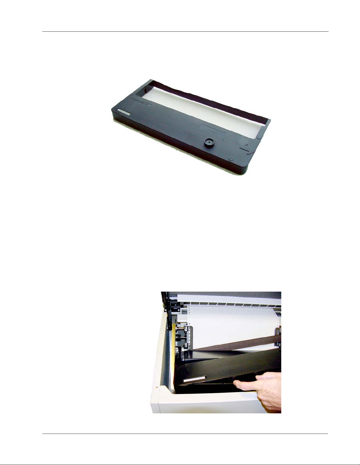
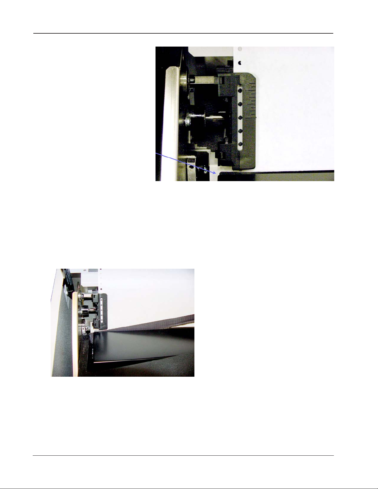
Installing the Ribbon Cartridge
Step 1.
Make sure the printer is Offline or power is off. Open the printer lid and
remove the old ribbon by lifting it straight up off of the Ribbon Platform.
Figure 1 - 7. Ribbon Cartridge
Installing Ribbon Cartridge
Step 2.
Remove slack in the new ribbon by turning the knob on the ribbon cartridge as
indicated by the arrow printed next to the knob, then slip the ribbon, left side
first, over the two ribbon guides and between the front and rear panels of the
ribbon shield on the printer.
Step 3.
Press down lightly on the cartridge while turning the ribbon knob as before
until it seats on first the left, (as shown), and then the right cartridge drive
posts. Make sure that the ribbon does not twist or fold over.
Figure 1 - 8. Installing the Ribbon Cartridge
Chapter 1: Setting Up Your Printer 1–17
Page 18
Installing Ribbon Cartridge
The front and rear
panels of the ribbon
shield
Figure 1 - 9. Ribbon Shield Panels
1–18 Operator Manual
The ribbon has been carefully positioned
between the two panels of the ribbon shield.
Page 19
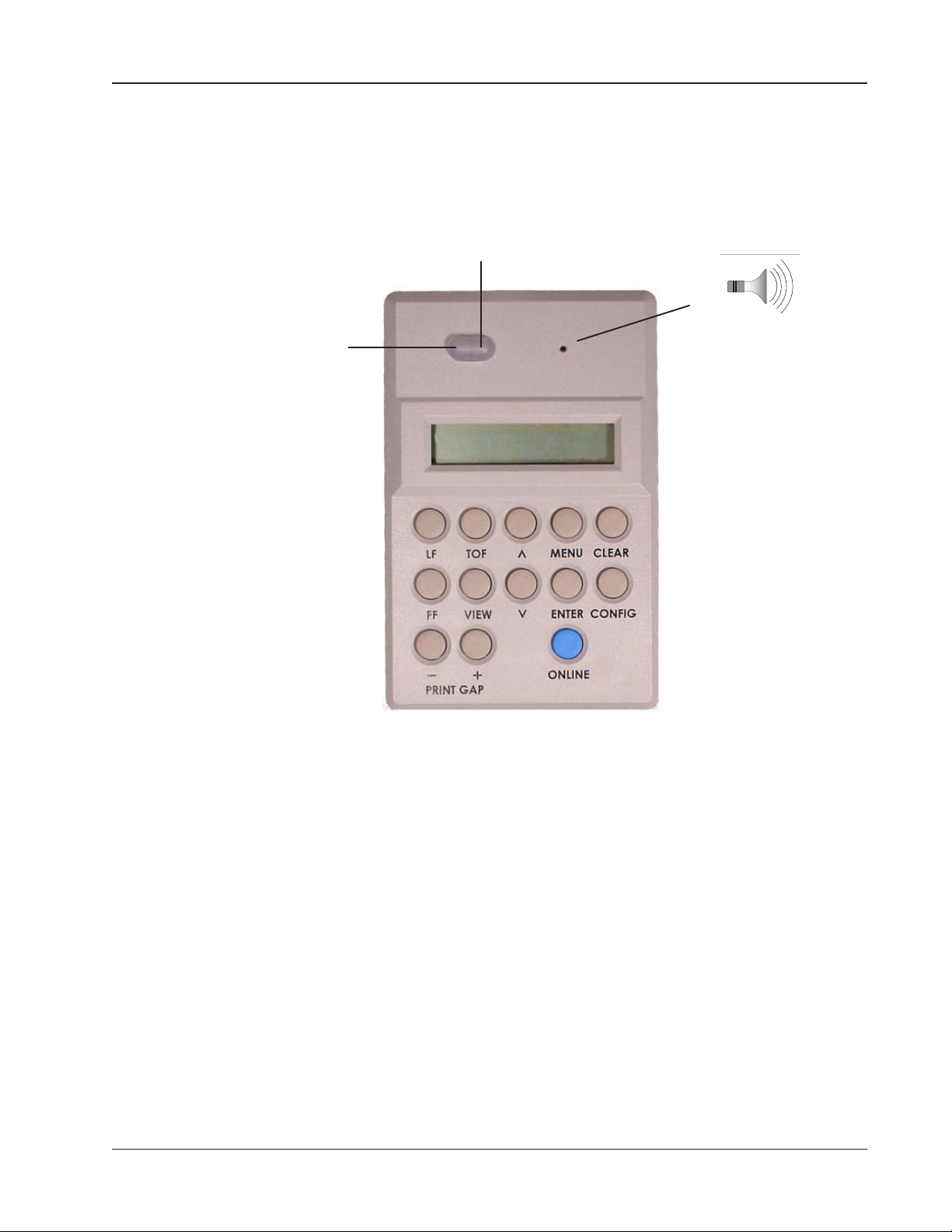
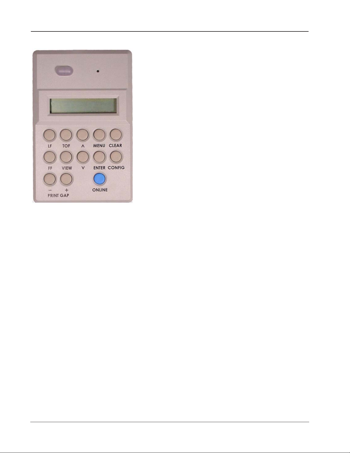
Control Panel Components
The Control Panel is located on the right front top of the printer housing. It is
used to program and direct most printer functions.
Red LED Indicator
Green LED Indica-
Control Panel Components
beeper
32-character
}
Figure 1 - 10. Control Panel
LED Indicators
The green ONLINE indicator illuminates whenever there is power to the
printer, and the printer is Online.
The red FAULT Indicator illuminates whenever an error or fault is detected. A
message also appears on the display to indicate what kind of fault is present (see
Appendix A for explanations of all error and fault messages).
LCD (Liquid Crystal Display)
The 32-character, 2-line Liquid Crystal Display shows printer status, menu
selections, normal, fault and error messages. It is divided into four main areas.
The displayed information will vary with menu selection and the configuration
of the printer.
Once the printer has been unpacked, the cables connected, the ribbon cartridge installed, and a box of paper (whether plain paper or pre-printed forms)
placed nearby, you are ready to load the paper and set the various parameters
via the Control Panel that will ensure that the 6300 Series printer performs
exactly as you need. This is covered in the next chapter.
Chapter 1: Setting Up Your Printer 1–19
Page 20

Blank
Page
1–20 Operator Manual
Page 21
Chapter 2
Introduction
This chapter covers how to load the paper and to set the print gap. It also covers
how to create saveable configuration settings for your own pre-printed forms.
Your printer is designed to use a continuous sheet, sprocket-fed paper. It can
handle:
• Six-part forms (1 original and 5 copies) with a maximum thickness of
• Page widths of 2.5" to 18" (6.4 cm to 45.7 cm).
Specific requirements for pre-printed forms are in Appendix C: Specifications.
.025" (0.6 mm).
Chapter 2: Loading Paper and Printing 2–21
Page 22
Standard Printing Mode
Loading Paper for Standard Printing Mode
Step 1.
Turn off the printer using the power switch on the back, or toggle the "Online"
button on the Control Panel until the LCD shows "Offline".
Step 2.
Raise the printer lid and open the doors on both tractors.
Figure 2 - 1. Inside Paper Inlet, visible when looking inside the printer cabinet.
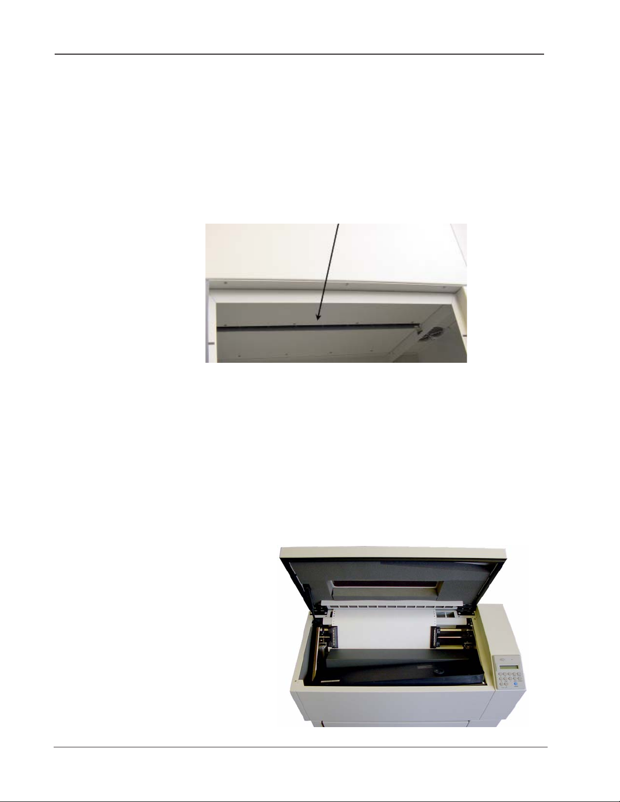
Step 3.
Step 4.
Step 5.
Open the new box of paper. Remove the box top so that the paper can be
pulled out freely. Open the front of the printer cabinet and place the new box
of paper inside.
Feed the paper up through the paper inlet, as shown in figure 2-1, a little ways
past the tractors and through the gap between the top back of the printer and
the lid (Figure 2-2). It will flow out between the paper chains and fold into the
wire rack near the floor (Figure 2-3).
Place the left-side paper holes onto the left tractor pins and close the tractor
door.
Feed paper
between the
lid and the
top of the
printer.
2–22 Operator Manual
Figure 2 - 2. Paper path past the lid.
Page 23
Step 6.
Standard Printing Mode
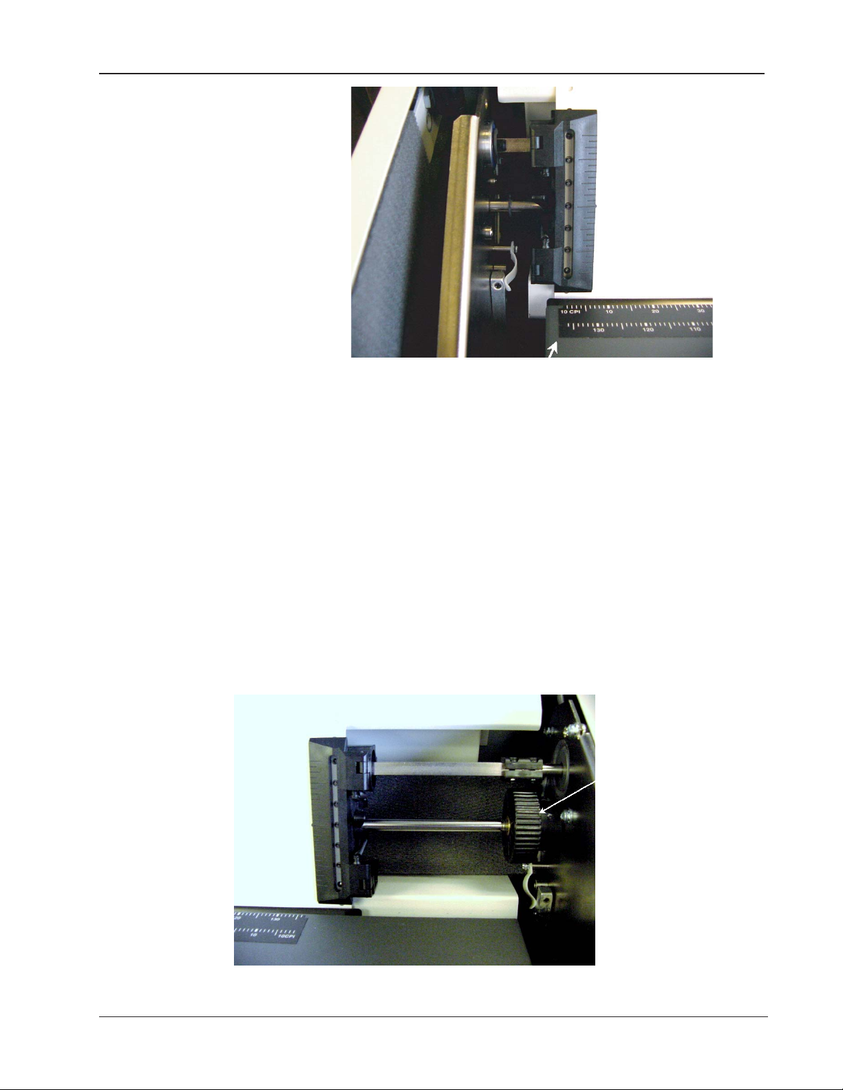
Figure 2 - 4. Column Alignment Scale
The Column Alignment Scale is on the top of the ribbon support platform. It is
to be used for general guidance in horizontally aligning the form for each
print job. The leftmost mark on the scale indicates the location of the first, or
leftmost, printable character. Each successive tick mark indicates the location
of additional 10 CPI characters.
Unlock the right tractor and move it so that the paper's holes align directly
over the tractor pins, making sure that the paper is straight, then close the
tractor door. Gently push the tractor to the right until the paper is smooth.
Unlock the left tractor and, keeping the paper reasonably taut, holding onto
both tractors, move the paper to the left or the right until it is roughly aligned
with the desired mark on the Column Alignment Scale. Lock both tractors.
Horizontal Vernier Wheel
Figure 2 - 5. Horizontal Vernier Wheel
Chapter 2: Loading Paper and Printing 2–23
Page 24
Standard Printing Mode
Fine-tuning the Column Alignment can be done in two ways:
(1) Rotate the Horizontal Vernier Wheel, which is located on the right end of
the shaft on which the tractors ride. Depending upon the direction the paper
needs to move, you will rotate the wheel either upwards or downwards.
(2) Use the Control Panel. Go Offline, choose Menu, then use the arrow keys to
get to the Operator Menu. Press Enter. Use the arrow keys to get to Forms.
Press Enter. Use the arrow keys to get to Horz Adjust. Press Enter. Use the arrow
keys to increase or decrease the number that appears in the lower right of the
LCD. This will shift the position of Column 1.
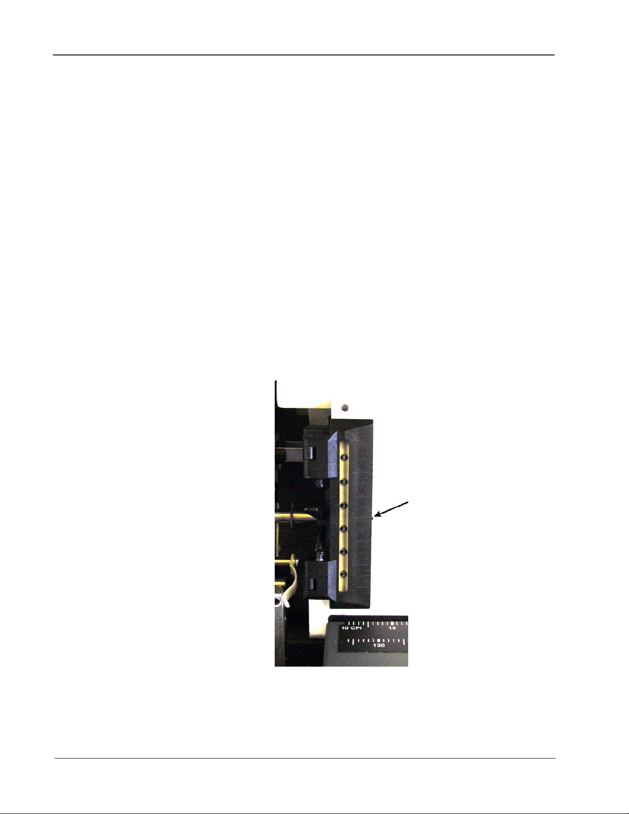
Step 7.
Set the Top of the Form (TOF). This is done from the Control Panel. If the
printer is not on, turn it on now. If necessary, press the Online key until
“Offline” is displayed. Use the up or down arrow keys to move the perforation
line on the paper so that it is aligned with the nubbin on the tractor door. Once
the paper is positioned, press the TOF key. The paper will move downward to
the “ready to print” position and the correct print gap will be set based on the
form thickness.
2–24 Operator Manual
Nubbin
- - - - - - - - - - - - - - - - - - - - - - - - - - - - -
-
Figure 2 - 6. Top of Form Nubbin
Page 25

Print Gap Adjustment
The 2900 Auto-Gap feature automatically sets the correct print gap based on
form thickness. Dedicated control panel keys also allow the print gap to be
adjusted for darker or lighter print based on user preference. For ease of paper
loading, the print gap is set to its widest position while the printer is not
printing. The Auto-Gap feature is automatically initiated under the following
conditions:
1. The Print Gap Mode is Auto, the printer has been off but is now turned on,
and a TOF is set before any printing has begun.
2. The Print Gap Mode is Auto, the printer has been off but is now turned on,
and a print run is started before TOF is set.
3. The Print Gap Mode is Auto, a Paper Out Fault has been cleared, and either
the TOF is set or a print run is resumed.
4. The Print Gap Mode is Auto, the printer has been off but is now turned on,
and an adjustment is made using the “-” or “+” Print Gap keys on the Control
Panel.
Print Gap
Even though the print gap value has been automatically determined, there
might be times when it needs to be further fine-tuned using the Control Panel
as described below under Manually Adjust Print Gap on Control Panel.
Gap Zone
The Gap Zone feature is used to set up a variable print gap for forms that
contain areas of varying thickness. This is done by creating a Gap Zone Profile
for the form, saving it in one of the ten saved configurations, then loading that
configuration whenever the particular form is used.
Print Gap Profile Mode
As previously described, the Print Gap Mode is set up in the Print Gap Category
of the Operator Menu. There are three Print Gap Modes. In Manual Mode, the
print gap is set manually using the Print Gap keys on the control panel. In Auto
Mode (default), the print gap is automatically detected whenever a new form is
loaded, and when the printer is powered on. Profile Mode is the mode that
must be set when using the Gap Zone feature, as described below.
Creating a Gap Zone Profile
A Gap Zone Profile is created automatically in four simple steps:
Step 1 – Load the Form
Load the form for which the profile will be generated. Be sure to set the
Top of Form position, and be sure that the Form Length is set properly.
Step 2 – Set Profile Mode
The Print Gap Mode is set up in the Print Gap Category of the Operator Menu.
Set the Mode Parameter to Profile. Press Operator Menu => PrintGap =>
Mode => Profile => Enter.
Chapter 2: Loading Paper and Printing 2–25
Page 26

Print Gap
Step 3 – Create the Profile
Select the Detect Parameter in the Print Gap Category of the Operator Menu.
Press Menu => up arrow until Detect shows => Enter. This will cause the
printer to move down the form in 1/6 inch increments, performing a print
gap detection operation at each increment. Note that this operation will
take approximately five to six minutes for an 11 inch form. Also note that
the print gap detection operation will leave small dots imprinted on the
form, so the sample form will have to be discarded.
If the printer is placed Online while in Print Gap Profile Mode, and a
profile does not exist (i.e. the Detect function was not performed), then a
Profile Error message will be displayed on the control panel.
Step 4 – Save the Profile
Once the Gap Zone Profile is created, you will probably want to save it for
future use. By saving the Current Configuration into any of the ten saved
printer configurations, the Gap Zone Profile is automatically saved along
with the other configuration parameters. If the Current Configuration is
not saved, the Gap Zone Profile just created will be lost when the printer is
turned off. See page 3-71 for directions in how to save a configuration.
Using a Saved Gap Zone Profile
Whenever a configuration with the Print Gap Mode set to Profile is loaded, the
Gap Zone Profile is automatically used when printing forms.
The Gap Zone Profile can be inhibited by changing the Print Gap Mode from
Profile to either Manual or Auto.
If the Form Length is changed to a value other than the one used to create the
Gap Zone Profile, the profile will be automatically disabled. If the printer is
then placed Online while still in Print Gap Profile Mode, a Profile Error message will be displayed on the control panel.
Fine-tuning the Automatic Print Gap Setting
When in Auto Gap mode, even though the print gap is automatically determined, you may need to further fine-tune it using the Control Panel. If your
print is not crisp and dark, you can adjust the print gap until all dots in the
printed characters are uniformly dark; be careful not to adjust the gap too tight,
to prevent paper jams.
The “-” and “+” Print Gap keys are normally locked to prevent accidental print
gap changes. These keys can be unlocked by holding down both keys simultaneously for approximately 3 seconds until the print gap adjustment display
appears. These keys will remain unlocked for approximately 1 minute after the
last key is pressed, after which they will once again be locked.
2–26 Operator Manual
Page 27

Print Gap
After unlocking the Print Gap keys:
Press one of the Print Gap keys on the Control Panel. This activates the Print
Gap adjustment display. Look at the Control Panel. The upper right region of
the LCD shows a number
by the detection process. The lower right region displays a “fine tuning” offset
which is added to the detected print gap to set the actual gap number. Initially
the “fine tuning” offset is 0, but it can be made negative or positive to adjust the
print gap smaller or larger, respectively, by pressing the
corresponding “-” or “+” Print Gap key on the control panel. The
offset range is limited by the printer. The lower left region of the
LCD provides a graphical indication of the adjustment being
made. There is a 5 second time-out: if no keys are pressed the
control panel display will revert to the prior menu and display.
Fine-tuning the print gap in this way may be done while printing
is in progress, allowing the operator to modify the gap and
immediately observe the effect it has upon print appearance.
See Chapter 3 for the specifics of the Print Gap menu.
1
corresponding to the optimal print gap determined
1. This number is for general reference. The precise relationship between the
displayed number and physical distance is complex and beyond the scope of this
manual.
Figure 2 - 7. Typical Display when Print Gap Mode is set to “Auto”
If you prefer to manually set the Print Gap for the forms you will be using:
Set Print Gap Detect Mode to Manual
Use the Arrow and Enter keys to select Menu => Operator Menu => Print Gap
=> Mode => Manual.
Step 1. Manually Adjust Print Gap on Control Panel
Press one of the Print Gap keys on the Control Panel. This activates the Print
Gap adjustment display. The lower right region of the LCD shows a number
corresponding to the current gap separating the hammer impactors from the
platen. Press the "+" or "-" Print Gap key to roughly match the setting to the
kind of paper that is loaded. This number will get larger or smaller respectively.
The range of allowed change is unrestricted over the complete gap range.
Typical values range from 54 to 110 for single-part through six-part forms.
1
2
1. This number is for general reference. The precise relationship between the
displayed number and physical distance is complex and beyond the scope of this
manual.
2. The control software will prevent selection of a print gap so small that it would
pinch the paper so tightly that it will bind within the mechanism.
Chapter 2: Loading Paper and Printing 2–27
Page 28

Manually Setting Print Gap
The lower left region of the LCD provides a graphical indication of the adjustment being made.
There is a 5 second time-out: if no keys are pressed
the control panel display will revert to the prior
menu and display. The Print Gap keys may be
pressed while printing is in progress, allowing the
operator to modify the print gap and immediately
observe the effect it has upon print appearance.
Figure 2 - 8. Typical display when adjusting Print Gap
Step 2. Run a Print Test
Press Clear. Make sure you're offline. Use the Arrow and Enter keys to select
Menu => Test Menu => Pattern => Print => Upper. Press Enter. This last action
begins running a print test. After a short while, press Enter to halt the test.
Examine what has been printed.
The print should be crisp and dark, with no smearing. The paper should move
smoothly through the print mechanism:
• If the print gap is open too far, the print may start fading out, especially
on the last sheet of a multi-part form.
• If the print gap is too narrow, the ribbon will start smearing ink on the
page, especially when the ribbon is moving and the paper is not. In
extreme cases, the shuttle may stop, and the paper may jam.
Repeat Step 1 and Step 2 until the print gap is set just right. This print gap
configuration can be saved and may be retrieved every time this particular
paper is loaded. What you have just set, though, will not change until someone
goes through Steps 1 & 2 again, or until a saved configuration with a different
print gap is loaded.
Setting Up Configurations
The 2900 printer can save up to ten personalized configurations, so you don't
have to recreate configurations you use frequently. Each configuration can be
given a label of up to 15 characters. When you first receive your printer, each
label is a generic "CONFIG" followed by a number 1 through 10. See page 3-71
for instructions on how to save configurations.
2–28 Operator Manual
Page 29

Chapter 3
Introduction
In this chapter you will learn how to use the Control Panel, how to navigate the
menus, and how to select and store parameter values as part of a configuration.
You will also learn how to obtain printouts that show all available parameters,
current configuration settings, and technical information like accumulated
running time and operating thresholds.
Let's begin with looking at the control panel display, and at each of the keys.
Control Panel Display
The information presented on the control panel display primarily depends
upon whether the printer is in normal operation, or in one of the menus.
Chapter 3: Printer Menus and the Control Panel 3–29
Page 30

Control Panel Display
The Display During Normal Operation
During normal operation, the top line of the display indicates the current state
of the printer, such as Online, Offline, or a fault message.
The second line of the display will indicate which of 10 saved configurations is
currently loaded. Each of the configurations can be assigned a unique name
and any of the configurations can be designated as the power up configuration.
By default, this line will display Config 1.
Green light is on
Current State
Paper Weight &
Hammer Impact
Current Configuration
Current State
The printer is “online” and the green light is on.
Current Configuration
This is the set of parameters, as detailed in the rest of this chapter, that have
been saved in Configuration 1. The asterisk indicates that Configuration 1 is
selected.
Figure 3 - 1. Control Panel Display for Normal Operation
Paper Weight & Hammer Impact
The lack of a symbol here means the hammer impact is set to “Normal” and the
paper weight is set to “Light”. See Table 3-1.
3–30 Operator Manual
Page 31

Control Panel Display
Indicator Paper Weight and Hammer Impact
(blank)
H
–
H
Table 3 - 1 Paper Weight & Hammer Impact Indicator
hammer impact setting is “Normal”
paper weight setting is “Light”
hammer impact setting is “Normal”
paper weight setting is “Heavy”
hammer impact setting is “High”
paper weight setting is “Light”
hammer impact setting is “High”
paper weight setting is “Heavy”
The Display When In A Menu
When a menu is selected, the top line of the display shows which menu, category, or parameter one is in.
The second line of the menu will display the next lowest level of the menu
hierarchy. If the top line displays a menu, the second line will display a category; and if the top line displays a category, the second line will display a
parameter; if the top line displays a parameter, the second line will display a
selection for that parameter. An asterisk is displayed in the far right column of
the second line when a parameter is selected.
No light is on
Menu, Category, or Parameter
Category, Parameter, or Selection
Figure 3 - 2. Control Panel Display for Menus
Chapter 3: Printer Menus and the Control Panel 3–31
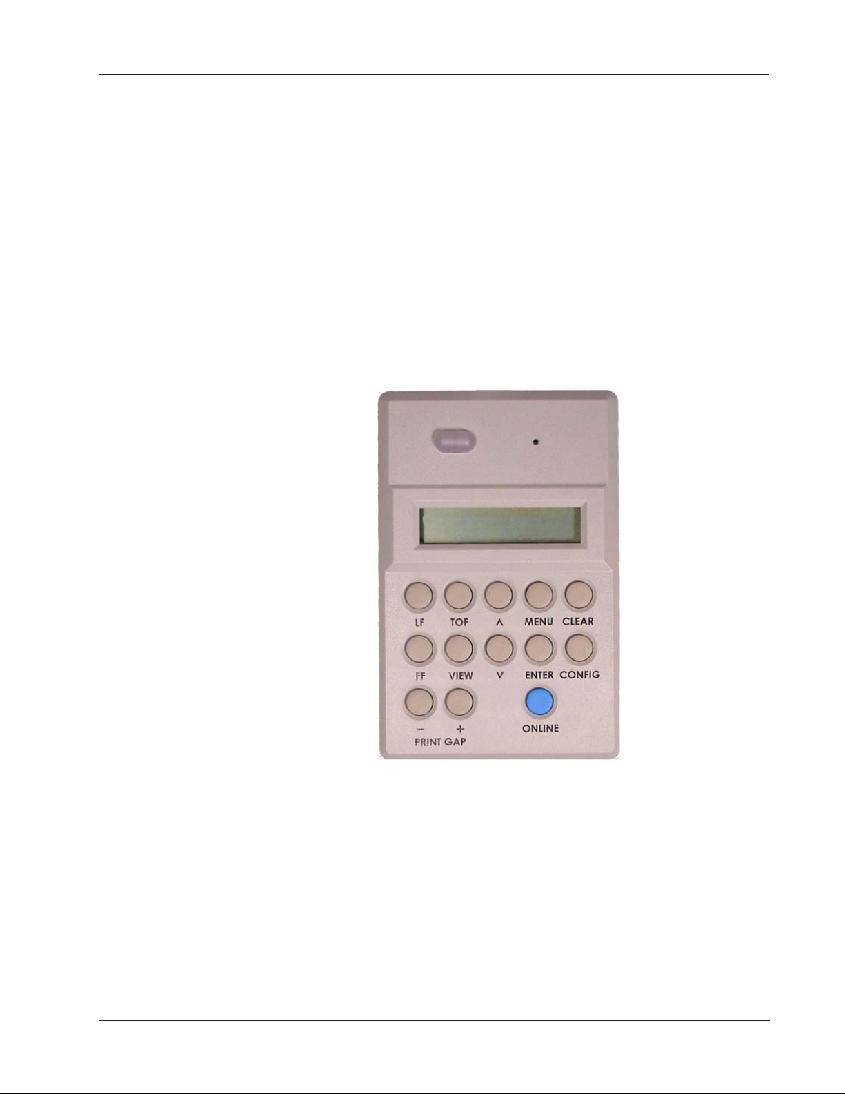
Page 32
Control Panel Key Functions
Control Panel Key Functions
Online Key
This key toggles the printer between Online and Offline
states, or exits from the menu directly to an Online state.
When the printer is Online, the indicator will light. In the
Offline state, you may change parameter selections, load
paper, and so on.
LF Key (Line Feed)
This key advances the paper one line. It performs the same
function whether the printer is Online or Offline. You may
auto-repeat this command by holding down the key.
While Offline With Data Buffered
Any buffered data falling in the next line (as defined by the
current LPI setting), prints. This repeats upon subsequent LF
keystrokes as long as there is data in the buffers. If pressed
while printing is in progress, the printer ignores the key
Figure 3 - 3. Control Panel
command and maintains the Top of Form position.
While Offline With No Data Buffered
Paper advances one line. While printing is in progress, the printer ignores the
command and maintains the Top of Form position.
While In A Fault Condition
Paper advances one line. No data is printed and the Top of Form position
moves down one line. This allows the use of the LF Key to advance paper while
in a Paper Out condition without printing any buffered data.
FF Key (Form Feed)
This key performs the same function whether the printer is Online or Offline.
While Offline With Data Buffered
Any buffered data falling between the current form position and the top of the
next form (as defined by the current Form Length setting), prints. This function repeats upon subsequent FF keystrokes as long as there is data in the
buffers. The printer ignores the command while printing is in progress and
maintains the Top of Form position.
While Offline With No Data Buffered
Paper advances to the top of the next form. The printer ignores this command
while printing is in progress and maintains the Top of Form position.
3–32 Operator Manual
Page 33

FF Key (Form Feed) continued
When In a Fault Condition
Pressing the FF Key while in a Fault Condition advances the paper one form.
No data prints, and the Top of Form position is maintained. This allows the use
of the FF Key to advance paper while in a Paper Out condition, without printing any buffered data.
TOF Key (Top of Form)
When you load paper, you line up the top of your form (usually the perforation) with the indicated position on the tractor (see Figure 2-6). Once the
paper is loaded, pressing this key moves the paper so that printing commences
at the proper position on the form.
View Key
Holding down this key moves the paper up so that you can see the last line that
was printed. If you press it while a job is printing, it will suspend the print job
until you release the key.
PRINT GAP + and - Keys
Pressing one or the other of these keys initiates a manual adjustment to the
current print gap. Pressing these keys can be used as a “shortcut” to get to the
Adjust display otherwise found by using the arrow and enter keys to select
Menu => Operator Menu => Print Gap => Adjust.
Control Panel Key Functions
Up and Down Arrow Keys
When Online
These keys make fine adjustments to the Top of Form position.
^
^
When Offline
These keys position the paper in preparation for setting the Top of Form
position. (In this mode, these keys will auto-repeat if you hold them down).
They are also for scrolling through Menu items (see Menu key, next).
After making adjustments, it's not necessary to reset the Top of Form (unless a
different top margin is required for a new form).
In Operator, Config, or Test menus
The Up and Down Arrow keys scan lists of categories, parameters, and selections.
Menu Key
Pressing this key allows you to access menu selections, which you can scroll
through using the Up and Down Arrow keys. To go back one level in the
hierarchy, press the Menu key, i.e., pressing the Menu key returns you to a
previous selection. This key command is only available when the printer is in
an Offline mode.
Chapter 3: Printer Menus and the Control Panel 3–33
Page 34

Control Panel Key Functions
Enter Key
In any of the menus, this key allows you to enter a lower level, to assign a selection to a parameter, or to perform a menu function.
When the printer is in a Paper Out Fault condition, and the PrntEOF parameter is set
to Off, pressing the Enter Key allows printing to the end of the current form. When
PrntEOF is set to On, the printer automatically prints to the end of the current form.
Clear Key
In Operator, Config, Test, or Help Menus
Pressing this key returns the printer to Offline status.
When Online
Pressing the Clear key clears the panel of any errors that do not cause the
printer to go Offline, such as "Parity Error."
When Offline
If the printer is in a clearable fault condition, the fault clears upon pressing the
Clear key. If it's not in a clearable fault condition, pressing the Clear key brings
up the Clear menu.
The Clear Menu
Clear Buffers
Clears all buffers. It also resets the application task to its initial state.
Clear Ribbon Count
When using the Ribbon Monitor feature, this selection must be used to clear
the ribbon count when changing ribbons. See the RibbonMonitor and
RibnMon Thresh setting in the Forms category of the Operator menu later in
the chapter.
Clear All Configs
Copies the Default Configuration settings into all saved configurations. Any
parameters not listed on the Configuration Report, such as special characters
downloaded from the host computer, are unaffected.
Clear Current Config
Copies the Default Configuration settings into the current configuration. Any
parameters not listed on the Configuration Report, such as special characters
downloaded from the host computer, are unaffected.
Clear Reset
The printer controller performs a hardware reset. You may use this in lieu of
cycling power to the printer. As with cycling power, the Powerup Configuration
is loaded as the Current Configuration (see later in chapter).
3–34 Operator Manual
Page 35
Clear Key continued
Config Key
Offline
This is a “shortcut” to the Load Configurations menu item (see later in chapter), allowing you to enter a menu where any of ten saved configurations can be
loaded into the Current Configuration.
Use the Up and Down Arrow keys to scroll through the configurations. Pressing the Enter key loads the one you choose.
Control Panel Key Functions
Chapter 3: Printer Menus and the Control Panel 3–35
Page 36

Using Menus
Control Panel Menus
This section discusses the menus and how to access and select values from them
for formatting documents, controlling print operations, or testing the printer.
The four main menus are Operator, Config, Test, and Help.
Categories, Parameters and Selections
Within the Operator, Config, and Test menus, there are a number of categories.
Within some categories there are sub-categories. Within each of these categories or sub-categories is a list of parameters. In some cases, a parameter can
execute a function upon pressing Enter, or in other cases, it displays a list of
options for that parameter.
The Help menu has no categories or parameters. You'll use this menu to print
out a list of all menus, categories, parameters and options.
Using Menus
Before going through these four main menus, let's learn how to access them.
Here are some things to remember:
• You must first be in Offline state to access menus, except for Print Gap.
• The Online key takes the printer Online and Offline.
• All scrolling is performed using the Up and Down Arrow keys.
• The Enter key selects parameter values or initiates a desired procedure.
• Selected options are marked with an asterisk (*).
• To exit Menu mode without making changes, depress the Clear key or
the Online key.
When the printer is Online, the green light is on and the Liquid Crystal Display
reads “Online”:
3–36 Operator Manual
Page 37

Using Menus
The name of the configuration displays on the lower line.
In this state, the only keys that respond are:
• Up and Down Arrows
•LF
•FF
• Clear
• View
• Online
• Print Gap (+ & - )
When the printer is Offline, no light is on and the display reads:
In the Offline state, pressing the Menu key gives you access to the first level of
the menu system. Upon doing this, the display reads:
Now, in the Offline state, you may access one of four available menus (Operator, Config, Test, and Help) by pressing the Up and Down Arrow keys, followed
by Enter.
As you scroll through using the Up Arrow key (with Operator Menu displaying
first) the display reads in order:
Config Menu
TCP/IP
Test Menu
Help Menu
(if LAN is installed)
Each of these menus except for Help has multiple levels of categories, selections and parameters. You access them by scrolling through the lists with the
Up and Down arrows, and by pressing Enter when you see the category, parameter, or selection you want.
Chapter 3: Printer Menus and the Control Panel 3–37
Page 38

Changing Form Length
Example: Changing Form Length Using the Menu System
If you wanted to change the Form Length from the default of 66 lines to 65
lines, this is how you do it:
1. Make sure your printer is in an Offline state. If it's not, toggle the
Online key.
2. Press the Menu key. The display reads:
3. Press Enter to select the Operator menu and press the down arrow key
until you see Forms. The display reads:
4. Press the Enter key to select Forms. Press the down arrow key until the
display reads Length (lines):
5. Forms Length (lines) is the selection you want, so press the Enter key.
The display reads:
(The asterisk means that 66 is the current selection, see page 3-42.)
6. You want to change this to 65. Press the Down arrow once and the
display reads:
3–38 Operator Manual
Page 39

Print Selections Report
7. Press the Enter key. The Form Length is set to 65, and an asterisk
appears beside the number. Exit the menu mode by pressing the Clear
key.
It's helpful to remember that at any time, you may leave a menu in one of two
ways.
• Press the Clear key to leave Menu Mode and remain Offline.
• Toggle the Online key to leave Menu Mode and return the printer to
Online.
How to Print a Control Panel Selected Options Report
The organization of the multilevel menus is shown on the Control Panel
Selected Options Printout. All of the current selections are marked with an
asterisk.
1. Toggle the Online key once or twice to clear the display and put the
printer Offline. Offline should be displayed and the green light should
be off.
2. Press the Menu key.
3. Use the Up or Down arrow keys until you see Help Menu on the display.
4. Press Enter.
The Control Panel Selected Options Report begins printing. When it's finished, press the FF key, tear off the sheet and use it to become familiar with all
of the menu items.
Chapter 3: Printer Menus and the Control Panel 3–39
Page 40

Operator Menu
⇒
Operator Menu
Font
1. Toggle the Online key once or twice to clear the display and put the
printer Offline. Offline should be displayed and the green light should
be off.
2. Press the Menu key.
3. Use the Up or Down arrow keys until you see Operator Menu on the
display.
4. Press Enter.
5. Use one of the arrow keys until the desired category appears; press the
Menu key if you need to back up a level.
Font Category
This category contains parameters that
control how print looks on a page and
the display language. Use the Arrow and
Enter keys to select Menu => Operator
Menu => Font to get here. They are as
follows:
Ser/Par Language
This parameter allows you to select the language used by emulations attached to
the Parallel, Serial, and LAN ports. The language selection defines the character substitutions in Hex locations 23, 24, 40, 5B, 5C, 5D, 5E, 60, 7B, 7C, 7D, and
7E. The default is US.
The details of the character substitutions can be found in the Line Printer
Applications Manual. The possible options are:
US German Norwegian/Dan
French UK Spanish
Swedish/Finish Italian Japanese
Portuguese Canadian Hungarian
Chinese French T6 Swedish T6
Italian T6 Canadian Alt Swedish Basic
French Withdrawn Nor/Dan T6 UK LG
Dutch LG Finnish LG Swiss LG
JIS Roman LG Nor/Dan LG Swedish LG
ISO Nor/Dan LG Portuguese LG VT 100
Turkish LG Cro-ASCII Nor/Dan Epson
French Epson UK Epson Spanish Epson
Italian Epson Norwegian Epson Danish Epson
Spanish 2 Epson Lat Amer Epson IRV
3–40 Operator Manual
Page 41

Ser/Par Character Set
This parameter allows you to select a character set that occupies locations Hex
80 through FF used by emulations attached to the Parallel, Serial, and LAN
ports. The default is Code Page 437:
The details of the character sets can be found in the Line Printer Applications
Manual. The possible options are:
Latin 1 8859-1 Latin 2 8859-2 Latin 9 8859-15
Cyrillic 8859-5 Greek 8859-7 Turkish 8859-9
Code Page 437 Code Page 850 Code Page 851
Code Page 852 Code Page 855 Code Page 857
Code Page 863 Code Page 866 Code Page 869
Code Page 928 Code Page 437G Code Page 866B
Code Page 1250 Code Page 1251 Code Page 1252
Code Page 1253 Code Page 1254 DEC MultiNational
DEC Turkish Siemens Turkish DEC Technical
DEC Supplemental Greek Supplemental Turkish Supplemental
Mazovia Kamenicky Roman-8
Katakana ISO 13 Line Draw Italic
Operator Menu ⇒ Font
Matrix
There are two font modes available on your printer. One mode is called Enhanced and the other is called CDF (for Constant Density Font). Enhanced
fonts include Draft and Data Processing, Near Letter Quality (Gothic and
Courier), and Optical Character Recognition Fonts (OCR-A and OCR-B).
Constant Density fonts include only Draft and Data Processing. In addition, the
available CPI options are different for each mode.
When this option is set to Enhanced, characters printed at 12, 13.3, 15, and
17.14 will use a denser character matrix than that of the default CDF matrix. If
this option is set to CDF and a CDF font matrix is not available for the current
Font Style and CPI, the Enhanced matrix will be selected.
CPI Selection is limited in the CDF Mode. The Specifications Section of this manual has
a listing of the CPI options available in Constant Density fonts. If you select a CPI
value, either through the Control Panel or via an escape sequence from the host computer,
that is not available in Constant Density Mode, the printer will automatically switch to
Enhanced Mode for printer output.
OCRA Density
This parameter sets the density for the OCRA font. There are three options:
Standard, Enhanced, and High. Standard is the default option and prints at 85
DPI vertical. Choosing the Enhanced option will cause the OCR-A font to be
printed at 96 DPI vertical. Choosing the High option will cause the OCR-A font
to be printed at 144 DPI vertical. Standard and Enhanced print at the same
speed, but the enhanced font is slightly shorter than the Standard. High prints
at a slower speed.
Chapter 3: Printer Menus and the Control Panel 3–41
Page 42

Operator Menu
Ser/Par Style
CPI (Characters Per Inch)
⇒
Font
This parameter allows you to select the font style used by emulations attached to
the Parallel, Serial, and LAN port. For emulations that support downloaded
fonts, you can use this parameter to select the download font. The default
option selection is DP.
Style options
Draft (High-speed)
DP (Data Processing, Default selection)
Gothic (Sans Serif NLQ)
Courier (Serif NLQ)
OCR-A (Optical Character Recognition)
OCR-B (Optical Character Recognition)
Download (Selects the downloaded font)
This parameter allows you to select characters per inch (CPI) settings. The
possible options are 5, 6, 6.67, 7.5, 8.33, 8.57, 10, 12, 13.33, 15, 16.67, 17.14, and
20. The default is 10 CPI.
Panel Language
This parameter allows you to set up the printer to display messages on the
Control Panel in a particular language. Printed reports also display in your
chosen language. The possible options are English (default), German, French,
Italian, Swedish/Finish, and Spanish.
OCR Standards
This parameter defines the combination of ANSI and DIN standards to be used
for the OCR-A and OCR-B character sets. The default value is dependent on
the emulation. The possible selections are:
A: ANSI B:ANSI This means ANSI OCR-A and ANSI OCR-B
A: DIN B:ANSI This means DIN OCR-A and ANSI OCR-B
A: ANSI B:DIN This means ANSI OCR-A and DIN OCR-B
A: DIN B:DIN This means DIN OCR-A and DIN OCR-B
Zero
As an aid in distinguishing zeros from the uppercase letter O, you can choose to
have your zeros slashed (Ø). The default parameter option is open (nonslashed) zeros.
Compressed 8
This parameter is either ON or OFF. Choosing ON causes all the characters
themselves that are printed at 8 LPI and above to be compressed vertically. The
result is increased white space between lines of print without changing the
current LPI setting. Compressed 8 works for any CPI setting. The default
selection parameter is OFF.
3–42 Operator Manual
Page 43

Forms Category
This category is used for setting up the
specifics for your individual forms. Use
the Arrow and Enter keys to select
Menu => Operator Menu => Forms =>
to get here.
Length (lines)
If you wish to define the length of your form in lines, you may select a form
length from 1 to 255. The default option is 66.
Length (inches)
If you wish to define the length of your form in inches, you may select a form
length from 0.1 to 25.5 inches. The default option is 11.0 inches.
LPI (Lines Per Inch)
This parameter allows you to set the lines per inch. The possible selections are
1.5, 2, 3, 4, 5, 6, 8, 9, 10, and 12. The default option is 6 LPI.
Operator Menu ⇒ Font
Top Margin
The option selected here determines where the first line of print is located on
the page. The Top Margin location is measured in the number of lines from
the current Top-of-Form location. The range is 0 to 255, with the default
option set to 0.
Bottom Margin
This parameter allows you to set the bottom margin. The Bottom Margin is
measured in the number of lines from the current Top-of-Form location. The
range is 0 to 255, with the default option set to 66.
The Bottom Margin (and the Top Margin) parameter option is defined in
terms of lines and so there is a natural relationship with the LPI option. For
example: Suppose the LPI option is set to 6 lines per inch and the Bottom
Margin option is set to line 60. The physical location on the paper of the
Bottom Margin will be 10 inches from the Top-of-Form location (60 lines
divided by 6 lines per inch). If the LPI is then changed to 10 lines per inch, the
Bottom Margin automatically changes to line 100 in order to maintain the
previous physical location for the Bottom Margin at 10 inches from the Top-ofForm location (100 lines divided by 10 lines per inch). A new Bottom Margin
setting can be selected, of course, if that is what is desired.
The Top Margin and Bottom Margin are thus translated into a physical location on the
paper. Subsequent changes in LPI affect this location. If the new location does not exactly
correspond with a line position, no asterisk is shown as a “current setting” indicator.
Chapter 3: Printer Menus and the Control Panel 3–43
Page 44

Operator Menu
Left Margin
Right Margin
⇒
Forms
You can place the left margin at any column number across the page, using
parameter options 1 to 272. The range of options for this parameter depends
on the CPI setting. Column 1 is the default option. The left margin must be
less than or equal to the right margin.
You can place the right margin at any column number across the page. As with
Left Margin, the range of this value depends on the CPI. Column 136 is the
default option. The right margin must be greater than or equal to the left
margin.
If a requested margin setting indicates a column number that is greater than
the maximum allowable for the current CPI, the printer will default to the last
valid setting.
The current value of the right and left margins reflects a physical location on the form,
and therefore changes when the CPI setting changes. If the physical location of the right
or left margin does not exactly correspond with a column position after changing the CPI
(characters per inch) setting, there will be no current setting indicator (asterisk). (See
this same discussion under Bottom Margin Parameter).
Horz Adjust
The print position on the form may be adjusted horizontally in increments of
1/30th an inch. The default option is 0.
Vert Adjust
The print position on the form may be adjusted vertically in increments of
1/72nd an inch. The default option is 0.
Print to EOF (End Of Form)
Before changing paper it is best to print to the end of the current form. This
parameter allows you to set up the printer to print to the end of the form
automatically. The options are On and Off, with the default at Off.
CAREFUL!
For Print to EOF to function properly the last print line of
the form must come before the perforation. If the Form
Length option allows printing to go over a perforation, it is
possible for the printer to continue printing in a paper out
situation without any paper in the printer, which may damage the printer.
3–44 Operator Manual
Page 45

Print to EOF (End Of Form) Continued
If Print to EOF is ON:
The printer automatically prints to the end of the form then stops. The display
reads Paper Out, the alarm sounds, and the FAULT indicator illuminates. At
this point you can load the machine with more paper. After you load paper,
adjust the top-of-form location and make sure the paper is feeding correctly.
When you are ready, depress the Clear key to clear the fault condition, then
place the printer Online and continue printing.
If Print to EOF is OFF, you have two choices:
Choice 1:
Load a new supply of paper into the printer. After paper has been loaded, set
the correct top-of-form location and check for proper paper feed. When you
are ready, depress the Clear key to clear the fault condition, then place the
printer Online and continue printing.
The printer will start printing where it left off, which may cause improper form and print
location alignment.
Choice 2:
Depress the Enter key. The printer prints to the end of the current form, then
the display reads Paper Out and the FAULT Indicator illuminates. At this point
you may load more paper on the printer. After loading paper, set the correct
top-of-form location and check for proper paper feeding. When you are ready,
depress the Clear key to clear the fault condition, then place the printer Online
and continue printing.
Operator Menu ⇒ Forms
The Paper Out Sensor will not work unless the Top-Of-Form location has been set properly.
Quick Access
This feature provides a way for the printer to position printed forms for quick
tear-off access. When Quick Access is enabled, the paper is moved to the tear
position by pressing the Enter key. If the printer is online and the current print
job is finished, pressing the Enter key will move the paper to the tear position
and the Quick Access Timeout will start. New print jobs will not start printing
until the timeout has expired and the paper has automatically moved to the
next available top of form. (This typically results in a blank form separating the
next-to-print form from the previously printed form.) Alternatively, the printer
may first be placed Offline before pressing the Enter key. Placing the printer
back online will align the paper as described above and printing will resume as
soon as data is received. The default option for the Quick Access parameter is
Disabled. The distance that the paper is ejected is set with the Eject Distance
parameter (below). The delay interval between print jobs is set with the Eject
Delay parameter (below).
Eject Distance
The Eject Distance parameter allows you to select the distance at which the
paper ejects during a Quick Access operation. The units are in tenths of an
inch, from 0.0 to 25.5; the default is 12.2 inches.
Chapter 3: Printer Menus and the Control Panel 3–45
Page 46

Operator Menu
Eject Delay
Impact
Paper Weight
⇒
Forms
This parameter specifies the timeout interval in seconds (after which printing
will resume) when Quick Access is Enabled while the printer is Online. The
default is 30 seconds.
This parameter has three options: Auto, which is the default, Normal, and
High.
The Paper Weight parameter defines the “paper moves” — how the paper
motion and printing work according to the thickness of the paper. If on Auto
(the default), the selection will be either Light or Heavy depending on the
Print Gap setting.
On the Auto setting Paper Weight uses the print gap to sense what is needed.
However, in some cases you may want to set it manually. For example, very
dense (yet thin) paper may need to be assigned a heavy paper weight to ensure
good print quality.
Fast Slew
Slew refers to the high speed paper motion that occurs whenever the printer
moves paper more than one line. If your forms are not too thin or fragile such
that output stacking is a problem, you can decrease the printer’s slew speed by
setting this parameter to Disabled. The default setting is Enabled..
Double Strike
When this parameter is set to Enabled, the printer strikes each dot twice. Use
this to get better print quality when you are printing on an exceptionally thick
form. Default is Disabled.
Enabling Double Strike decreases the printer throughput by approximately
50%.
RibbonMonitor
This parameter enables the Ribbon Monitor feature. The options are Enabled
and Disabled (default).
This feature helps the printer operator determine when to replace ribbons for
optimum and consistent print quality. It works by counting the estimated
number of characters printed as jobs are printed. Since ribbons are rated for an
estimated number of characters, when the character count threshold is reached
for the current ribbon the operator is notified via the panel that the ribbon
needs to be replaced.
Ribbon Monitor can be disabled at any time. However, the “characters printed count” is
reset to zero whenever Ribbon Monitor is enabled, so enabling the feature should only be
done with a fresh ribbon.
3–46 Operator Manual
Page 47

If the Ribbon Monitor Fault occurs, and is cleared without the ribbon life
threshold being increased or the ribbon count reset to zero, the “Replace
Ribbon” message will reappear approximately every one million characters until
one of these operations is performed. This message will also appear upon
powerup if the ribbon count is above the threshold at that time.
RibnMon Thresh
This parameter sets the ribbon life threshold of the Ribbon Monitor feature.
The default option is 40, assuming that a 40 million character ribbon is being
used. This option should be changed to 60 or 250 if a 60 million or 250 million
character ribbon is used. The setting can be further refined based on the
application being printed.
Ribbon Monitor Operation
When the number of characters printed reaches the ribbon life threshold, the
current print job will stop, the Fault indicator will light, and the Replace Rib-
bon message will appear. When this situation occurs:
• Clear the fault with the Clear key. The fault indicator should turn off
and the Replace Ribbon message should disappear. (As explained
under RibbonMonitor, see above, the fault message may recur.)
• Look at the recently printed output of the printer to determine if the
ribbon is exhausted. If the quality of the output is still acceptable, you
can increase the ribbon life threshold through the RibnMon Thresh
option. The printer can then be placed back online and printing will
resume.
• If the printed output is too light, then the ribbon is exhausted. Replace
the ribbon with a new one, and reset the ribbon count with Clear Menu
Ribbon Count. The printer can then be placed back online and printing will resume.
Operator Menu ⇒ Forms
If the printing application is particularly heavy, it may be necessary to decrease the
threshold.
The current Ribbon Monitor status can be obtained by printing a Calibrations
Report (Menu => Configuration Menu => Printer => Report). This report will
indicate whether Ribbon Monitor is enabled, the estimated number of characters printed since Ribbon Monitor was last reset, and the selected threshold.
If the LAN interface is installed, the Ribbon Monitor status can be viewed
graphically in WebPanel in which the size of the gas gauge bar decreases as a
percentage of remaining expected ribbon life. The color of the bar is green
when expected remaining ribbon life is between 51% and 100%, yellow when
between 26% and 50%, and red when 25% or less. WebPanel can also be
configured to send an Email Notification when the expected remaining ribbon
life falls to 25%.
Chapter 3: Printer Menus and the Control Panel 3–47
Page 48

Operator Menu ⇒ Print Gap
Perf Skip
This parameter will enable the automatic perforation skip feature that will
cause the print gap to automatically increase significantly between the last line
printed on the current form and the first line printed on the next form. This
feature is useful when using heavy forms that have a large perforation “tent”
that can get hung up in the print station. The options for this parameter are
Enabled and Disabled (default).
When the Perf Skip parameter is enabled, the printer throughput will be reduced due to
the time required to automatically open and close the print gap.
Print Gap Category
This category has the parameters for
setting the different aspects of the print
gap mechanism. Use the Arrow and
Enter keys to select Menu => Operator
Menu => Print Gap to get here.
Detect
When the enter key is pressed to select this parameter, the platen squeezes
against the paper at the current paper position. The resulting optimal print gap
setting is stored in the current configuration. The platen opens up fully after
this operation.
Adjust
This is where the print gap may be set, if Mode is set to Manual, or fine-tuned if
Mode is set to Auto. The final print gap value may be saved in a configuration
associated with this paper form.
Fine-Tuning when Mode is set to Auto
The upper right region of the LCD shows a number
1
corresponding to the
optimal print gap determined by the detection process (the gap separating
the hammer impactors from the platen). The lower right region displays an
adjustment offset number associated with fine-tuning. When the operator
presses the “-” or “+” Print Gap key on the control panel, this number will
get smaller or larger, respectively. The range of allowed change is restricted
by the auto gap firmware. The lower left region of the LCD provides a
graphical indication of the adjustment being made.
1. This number is for general reference. The precise relationship between the displayed number and
physical distance is complex and beyond the scope of this manual.
3–48 Operator Manual
Page 49

Reset
Operator Menu ⇒ Print Gap
Fine-Tuning the Print Gap Manually
The lower right region of the LCD shows a number
current gap separating the hammer impactors from the platen. Press the "+"
or "-" Print Gap key to roughly match the setting to the kind of paper that is
loaded. This number will get larger or smaller respectively. The range of
allowed change is unrestricted over the complete gap range.
region of the LCD provides a graphical indication of the adjustment being
made.
2. This number is for general reference. The precise relationship between the displayed number
and physical distance is complex and beyond the scope of this manual.
3. The control software will prevent selection of a print gap so small that it would pinch the paper so
tightly that it will bind within the mechanism.
This parameter resets the gap setting. If Detect Mode is Auto, the next time the
TOF key is pressed or a print run is started, a print gap detection operation will
be performed. If Detect Mode is Manual, the Print Gap will be set to 190 (the
maximum gap setting).
2
corresponding to the
3
The lower left
Mode
This parameter determines whether a print gap detection operation is performed automatically. Auto is the default and if set, a gap detection process will
be performed when:
(1) the printer has been off but is now turned on, and a TOF is set;
(2) the printer has been off but is now turned on, and a print run is started;
(3) a Paper Out Fault has been cleared, and either the TOF is set or a print
run is started;
(4) the printer has been off but is now turned on, and a print gap adjustment
is made using the Print Gap “+” or “-” keys.
If Manual is selected, a gap detection process will not be performed under the
four conditions listed above. Instead, whenever the print gap set point must be
applied, the print gap value stored in the current configuration will be used.
The allowable adjustment range is 0 to 190. If the current configuration has an
uninitialized gap value, the platen will move to the default value of 190.
Profile is the mode that must be set when using the Gap Zone feature.
Chapter 3: Printer Menus and the Control Panel 3–49
Page 50

Operator Menu ⇒ Print Gap
Creating a Gap Zone Profile
A Gap Zone Profile is created automatically in four steps:
Step 1 – Load the Form
Load the form for which the profile will be generated; doublecheck the Top
of Form position with Form Length.
Step 2 – Set Profile Mode
Set the Mode Parameter to Profile.
Step 3 – Create the Profile
Select the Detect parameter. Note that this operation will take approximately five to six minutes for an 11 inch form. Also note that the print gap
detection operation will leave small dots imprinted on the form, so the
sample form will have to be discarded.
If the printer is placed Online while in Print Gap Profile Mode, and a
profile does not exist (i.e. the Detect function was not performed), then a
Profile Error message will be displayed on the control panel.
Step 4 – Save the Profile
Once the Gap Zone Profile is created, you will probably want to save it for
future use. By saving the Current Configuration into any of the ten saved
printer configurations, the Gap Zone Profile is automatically saved along
with the other configuration parameters. If it isn’t saved, it will be lost when
the printer is powered off.
Also see page 2-30 on Creating a Gap Zone Profile, and page 2-31 for Using
a Saved Gap Zone Profile.
Detect Distance
This parameter sets the vertical distance from the TOF to the position where
the paper is squeezed during a Detect operation. The allowable range is 0
inches to the current form length, with increments in tenths of inches. The
default value is 2.0 inches. The print gap is detected at a point away from the
perforation in order to avoid false readings that could be caused by uneven
areas around the perforation. The default distance of 2.0 inches is usually
adequate unless there are forms anomalies (such as an attached card or an
envelope window) in that area.
3–50 Operator Manual
Page 51

VFU Category (Vertical Format Units)
Use the Arrow and Enter keys to select
Menu => Operator Menu => VFU to get
here.
VFU Enable
A Vertical Format Unit is a means for loading sets of vertical tabs. These vertical
tabs define various parameters of a form and apply only to the emulations
which make explicit use of the VFU channels. Setting this to Enabled causes
the printer to use the last loaded EVFU instead of using the Form Length, Top
Margin, and Bottom Margin settings. When an EVFU is loaded, this parameter
is automatically set to Enabled. The default is Disabled.
VT Channel (Vertical Tab Channel)
You can select which VFU Channel is designated as the Vertical Tab Channel.
This parameter applies only to the emulations which make explicit use of the
VFU channels. Options are 1 - 12 and Unused. The default depends on the
emulation as defined in the table on page 3-57 under Ser/Par Emulation.
Operator Menu ⇒ VFU
Skip When
This parameter applies only to the emulations which make explicit use of the
VFU channels. It designates where the Skip Length distance will begin - before
or after the Bottom of Form channel. The Skip location is determined by using
the designated Bottom-of-Form Channel in the downloaded VFU. The Skip
When only functions when the VFU Environment is Enabled. The default
depends on the emulation as defined in the table on page 3-57 under Ser/Par
Emulation.
Chapter 3: Printer Menus and the Control Panel 3–51
Page 52
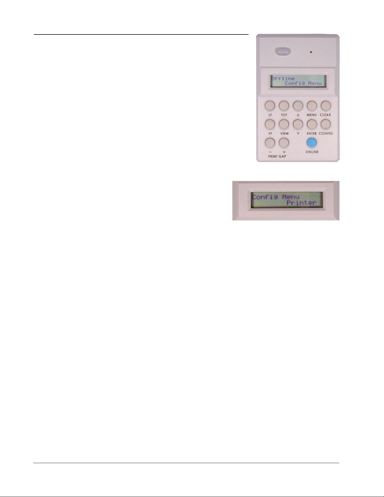
Config Menu ⇒ Printer
Config Menu
Following are explanations of each category and
parameter in the Config Menu. For all available
options under each parameter below, consult the
Help Menu printout. The categories here are
Printer, Codes, Graphics, Configurations, Serial
I/O, Parallel I/O, IntelliFilter, and when the
options are installed, Twinax/Coax and IPDS.
Printer Category
Use the Arrow and Enter keys to select
Menu => Config Menu => Printer to get
here.
Powerup
This parameter sets the printer either Online or Offline when the power switch
is turned on. The default is Offline.
Ser/Par Emulation
This parameter allows you to define which set of printer control commands will
be emulated for data received on the Serial and Parallel ports (except LANIPDS). Epson DFX-9000 is the default selection. Other selections include IBM
Proprinter III XL and MTPL.
LAN Emulation (LAN Interface only)
This parameter is used to select the emulation attached to the Ethernet port
when using the LANPlex interface. The options are the same as for the Ser/Par
Emulation.
Dump Mode
This parameter is used to troubleshoot problems that may arise when processing data. It places the printer into a Hex Dump Mode. You can select three
styles of printouts for use as debugging tools. The selections are:
OFF: Dump Mode is disabled. (Default selection)
Style1: Two column output. Text, spaces, and control codes are printed in
hexadecimal code format in one column and ASCII equivalents in another
column.
Style2: Only control codes are printed in hexadecimal format. ASCII characters are printed as is and escape sequences force a new line.
3–52 Operator Manual
Page 53

IO Hold
Report
Config Menu ⇒ Printer
Style3: Control codes and spaces are printed in hexadecimal format. ASCII
characters are printed as is and escape sequences force a new line.
This parameter allows you to set the amount of time the printer remains locked
onto the I/O on which it is receiving data after data transmission stops. You can
set this to be 5 - 600 seconds. Default is 30 seconds.
Use this parameter to print or display a report of the following, using the arrow
keys to cycle through the list of reports to the one that is needed. Pressing Enter
will start the report printing:
Current Config: This produces a printed report of the current printer configuration. The report contains a header which identifies the installed software and
interface, any options that are installed, and statistics for time powered on, time
printing, and total lines printed.
Configs 1-10: Produces a printed report of any of the saved printer configurations. The report contains a header which identifies the installed software and
interface, any options that are installed, and statistics for time powered on, time
printing, and total lines printed.
Calibrations: Produces a printed report of the printer calibration settings. The
report contains a header which identifies the installed software and interface,
and statistics for time powered on, time printing, and total lines printed. The
body of the report shows the values of the current sensor and print timing
calibrations. It also contains a report of the Ribbon Monitor status.
Ribbon Count: Displays the number of characters printed since the ribbon
count was last reset.
Last Fault: Displays the last fault message on the control panel display.
Fault Log: Displays the fault log on the control panel display.
All Configs: Produces a printed report of all the saved printer configurations.
The report contains a header which identifies the installed software and Version: Displays the version numbers of the installed software on the control
panel display.
IntelliFilter: Prints the currently downloaded IntelliFilter.
Chapter 3: Printer Menus and the Control Panel 3–53
Page 54

Config Menu ⇒ Printer
Beeper Mode
When a fault event occurs, the beeper will sound. There are two options: Single
or Persistent. In the Single mode, each fault event will cause the fault alert
beeper to produce just one short-duration audio tone and then to remain
silent. In the Persistent mode, a fault event will cause the fault alert beeper to
periodically produce a short-duration audio tone that cycles approximately
once per second and will persist until the operator clears the fault.
Beeper Volume
Here the user selects the loudness of the audio tone produced by the fault alert
beeper. The options are Silent, Low, Medium – the default, or High. Pressing
the Enter key will produce a short sample tone that corresponds to the option
selected.
3–54 Operator Manual
Page 55

Codes Category
In this category are choices that allow
you to determine the printer’s response
to certain conditions and to assign values
to parameters that are used by other
commands or escape sequences. Use the
Arrow and Enter keys to select Menu =>
Config Menu => Codes to get here.
Auto LF (Line Feed)
Auto LF causes the printer to perform a Line Feed each time it receives a
Carriage Return Control Code. This option is available for host systems that
cannot send a Line Feed Control Code.
Some computers automatically generate a Line Feed of their own at the right
margin. If your system does this and if Auto LF is enabled, it will result in a
double-space between lines of print. Consult your computer manual to determine whether this function should be turned off or on. Default is OFF.
Auto CR (Carriage Return)
Auto CR allows the printer to perform a Carriage Return (moves print location
to the left margin) when it receives either a Line Feed or Vertical Tab Control
Code. The default value is dependent on the emulation (see the list on page 359 under Ser/Par Emul).
Config Menu ⇒ Codes
Line Wrap
If the printer gets to the right margin without receiving a paper movement
command, the Line Wrap parameter dictates how the rest of the data will be
treated. If Line Wrap is OFF the excess characters are lost. If Line Wrap is ON,
printer response is determined by the Wrap Line Feed (see below).
If Line Wrap is ON and Wrap LF is OFF, the printer performs a Carriage Return only
and overprinting can result.
If Line Wrap is ON and Wrap LF is ON, the printer performs a Carriage Return
plus a Line Feed and excess characters are printed on a new line at the left
margin.
The default value is dependent on the emulation (see the list on page 3-59
under Ser/Par Emul).
Wrap Line Feed
This parameter works in conjunction with the Line Wrap parameter above. The
default value is dependent on the emulation (see the list on page 3-59 under
Ser/Par Emul).
Chapter 3: Printer Menus and the Control Panel 3–55
Page 56

Config Menu ⇒ Codes
Print on CR
This parameter is intended for use by customers whose applications embolden
characters by using a CR-only method to selectively reprint all or parts of a line.
Off: Ignore bolding, print as regular text (Default setting)
Double Strike: Print line, then backup to reprint (bold by overstriking)
Bold: Print line once, bold portions printed with enhanced "bold"
For example, the application may embolden the word "bold" in a sentence by
sending (^ marks a space) the following:
With "Double Strike" selected, bolding is accomplished by re-striking the
characters at the same dot positions. This requires a 1-line backup after printing
each <CR> pass; some applications use many passes to print a single bolded line,
so printing throughput may be reduced accordingly.
With "Bold" selected, bolding is accomplished by rendering the bolded characters twice, one with a small offset to create a "shadow" effect. The resulting print
is thicker and thus appears darker. This is the same technique used with the
"bold" character attribute selected via emulation escape sequences.
style
This is bold<CR>^^^^^^^^bold<CR><LF>
Form Feed at TOF
This dictates how the printer will respond to a Form Feed Control Code received from the host computer when it is already at a top-of-form location. If
set to Disabled, the printer ignores the Form Feed Control Code sent from the
host. If set to Enabled (default selection) the printer performs the requested
form feed and advances to the next top-of-form.
ESC
This parameter is valid only in the Tally ANSI and LG emulations. When set to
Disabled, the ESC control character is ignored. The default is Enabled.
Alt ESC (Alternate Escape)
This parameter is only valid in the Tally ANSI and LG emulations. When set to
Enabled, a "^" (carat) character in column 1 (left margin) followed by a CR or a
CR LF can be used in place of the ESC control code. The default is Disabled.
ESC (see above) must also be Enabled for this to work.
Upper Only
This parameter allows you to set up your printer to print in uppercase characters only from the active Character Set. When this parameter is enabled, the
lowercase characters in Hex positions 61 through 7A are overwritten by the
uppercase characters in positions 41 through 5A. The default selection is
Disabled.
3–56 Operator Manual
Page 57

Code 7F
This parameter allows you to dictate how the printer will react when it receives
a Hexadecimal code 7F. The default value depends on the emulation. (See
the Emulation Parameter, presented earlier in this chapter.)
Ignore: The code is ignored.
Delete Char: The previous character is deleted.
Delete Buffer: The previous characters on the current print line are deleted.
Space: A Space character is substituted.
Fill: A Fill character is substituted.
Print 80 - 9F Hex
This parameter defines whether locations 80 through 9F Hex are to be treated
as control characters or printable characters. The function of the control
characters in this area depends on the emulation. The options are ON (printable characters) – the default, or OFF (control characters).
Ignore Char
This parameter allows you to select a character that will be ignored in the
incoming data stream. Ignore Char functions in all emulations and nondownloadable print modes. It does not function in plot mode, font download,
or VFU download. Options are 0-255, referring to the decimal value of any 8bit character, or OFF. Default is OFF.
Config Menu ⇒ Codes
Sub Char From
This parameter allows you to select a character that will be replaced by the
character designated by the Sub Char To parameter. It functions in all emulations and non-downloadable print modes. It does not function in plot mode,
font download, or VFU download. Default is OFF.
Sub Char To
This parameter allows you to select the character that will replace the character
designated by Sub Char From. It functions in all emulations and nondownloadable print modes. It does not function in plot mode, font download,
or VFU download. Default is OFF.
Chapter 3: Printer Menus and the Control Panel 3–57
Page 58

Config Menu ⇒ Configurations
Configurations Category
The 6300 Series printer can save up to
ten personalized configurations, so you
don't have to recreate configurations you
use frequently. In addition, each configuration you save can be tagged with a label
of up to 15 characters. When you first
receive your printer, each label is a generic "CONFIG" followed by a number 1
through 10. Use the Arrow and Enter keys to select Menu => Config Menu =>
Configurations to get here.
Save
If you have a configuration you are going to use multiple times, you may want
to save it. You use SAVE to do so.
How to Save Configurations:
• Set up all the various printer parameters the way you want them.
• Make sure the printer is Offline by pressing the Online key until the
green light goes off and Offline appears in the LCD
• Press the Menu key.
• Use the Up or Down Arrow keys to find the Config menu, and press
Enter.
• Use the Up or Down Arrow keys to find Configurations. Scroll through
the list of configurations. If you have not labeled them they will be
listed as CONFIG 1 - CONFIG 10. Press Enter to save your configuration into any of these slots.
Next time you want to use this configuration, use LOAD.
Load
You will use this parameter to load any of your saved configurations into the
Current Configuration. Use the Load parameter to choose the configurations
you've previously saved.
Powerup Config
You will use this parameter to designate any of the saved configurations as the
configuration that is loaded when the printer powers up. Scroll through the
Powerup Config list of configurations to select the configuration you want to
use, then press Enter. The default Powerup Config is CONFIG1.
Config n Label - (where n = 1 to 10)
You may want to call your configurations something more intuitive than
CONFIGs 1 through 10. This is used to set 15-character labels for each configuration slot.
3–58 Operator Manual
Page 59

Config Menu ⇒ Configurations
How to label a configuration slot
• Make sure the printer is Offline.
• Press the Menu key to enter Menu mode.
• Use the Up and Down Arrow keys to get to the Config menu, and then
press Enter.
• Use the Up and Down Arrow keys until the display reads Configurations, then press Enter.
• Use the Up and Down Arrow keys until you see Config n label, where n
is the number of the configuration you want to label (1-10). Press Enter.
• A cursor appears underneath the first letter (C). Use the Up and Down
Arrow keys to scroll to the number or letter you want to use. Repeat for
up to 15 characters, pressing Enter after each letter. You must press
Enter 15 times even if your label is shorter.
• Press Clear or Menu to save it. Now, when you use SAVE or LOAD, this
configuration name appears in the slot you've chosen.
Chapter 3: Printer Menus and the Control Panel 3–59
Page 60

Config Menu ⇒ Serial I/O
Serial I/O Category
Serial Interface is a style of host computer-to-printer I/O communications. It
requires certain parameters to be properly set in order for the printer and host
computer to communicate. Use the
Arrow and Enter keys to select Menu =>
Config Menu => Serial I/O to get here.
Baud
The Baud parameter allows the user to set up the printer to receive data at
different transmission speeds. The baud rate must be the same value at both ends of
the communication line. 9600 is the default.
Data Bits
You can choose the number of data bits per byte. 8 bits is the default.
Stop Bits
This parameter sets the number of serial stop bits. 1 is the default.
Parity
8th Bit
Protocol
Parity is a method the printer uses to verify that each byte of data it receives is
exactly what the host computer transmitted. When selected, it keeps track of
the number of high bits in each byte (either odd or even). Default is None. The
printer must match the parity of the host computer.
If 8 bits per byte is selected under Data Bits above, you use this parameter to
determine how the 8th bit is to be used. If this bit is to be ignored, the parameter should be set to Unused. If the bit is to be used, the parameter should be
set to Data. Data is the default, used for 8-bit characters.
The printer and host computer must establish common signals, understood by
both units, for indicating when to send new data and when to stop sending
data. For IPDS, this parameter allows the serial protocol to be set to either
Ready/Busy or XON/XOFF. For all other printers, there are six additional
block mode protocols. The eight protocols are:
Ready/Busy (Default selection)
Xon/Xoff
and six Block Mode protocols:
Enq/Ack (Enquiry/Acknowledge)
Etx/Ack (End of Text/Acknowledge )
Etx/Ack/Nak (End of Text/Acknowledge/Neg. Acknowledge )
Ack/Nak (Acknowledge/Negative Acknowledge )
Xon/off/Etx/Ack (XON/XOFF/End of Text/Acknowledge )
Xon/off/Enq/Ack (XON/XOFF/Enquiry/Acknowledge)
The above protocols are explained in detail in the Applications Manual.
3–60 Operator Manual
Page 61

Status Enquiry
When this parameter is enabled, the host may send an enquiry packet to the
printer requesting status. The printer will then send back a 1 byte packet
denoting the status of the printer. If this option is set to OFF (the default), no
packet will be sent back. The Status Enquiry feature may be enabled in conjunction with any other protocol. When enabled and the host sends an ENQ
character, the printer responds by sending a printer status byte. The status byte
is designed to be a printable code and is the only printable code the printer can
transmit.
The bit pattern is as follows:
Bit Meaning/Value
7 Parity if 7 bit data and parity enabled (MSB)
6 Always a 1
5 1 if Data Overrun
4 Always a 0
3 1 if Parity Error
2 1 if Paper System Error or Platen Open
1 1 if Offline
0 1 if Busy (fault or buffer full) (LSB)
Config Menu ⇒ Serial I/O
The Status Enquiry Feature is slightly different when the current emulation is
the HP2564C. Instead of responding to the ENQ character, the printer will
respond to the ESC ? DC1 sequence. The bit pattern of the status response is as
follows:
Bit Meaning/Value
7 Parity if 7 bit data and parity enabled (MSB)
6 Always a 0
5 Always a 1
4 Always a 1
3 0 if Parity Error, Data Overrun, or Buffer Overflow
2 1 if Offline
1 1 if Busy (fault or buffer full)
0 1 if Paper System Error or Platen Open (LSB)
DTR Function
This parameter allows the user to change the operation of the Data Terminal
Ready (DTR) line on the printer interface. The DTR line is used to indicate
printer status to the host computer.
Busy (Default): In this mode the DTR line is used to signal the host to stop
sending data because the printer buffer is 85% full. However, some cabling
systems require the DTR Line of the printer to be configured differently. This
cabling scheme can interfere with printer transmission or host reception of the
Xoff signal when using the Xon/Xoff Serial Protocol. This situation can result
in Buffer Overflow and Data Overrun situations and loss of data.
Chapter 3: Printer Menus and the Control Panel 3–61
Page 62

Config Menu ⇒ Serial I/O
DTR Function continued...
Offline: When this option is active, the DTR Line is used to signal only that the
printer is Online or Offline. Unlike the Busy option, the Offline option will
not interfere with operation of the Xon/Xoff Communication Protocol.
Power: When this option is active, the DTR Line is used to signal the host that
the printer is powered up. This DTR Selection will not interfere with host
reception of the Xoff/Xon Serial Protocol, because unlike the Busy selection,
the DTR Signal is not toggled at the same time as the Xoff Signal. When using
this option, the DTR Polarity parameter must be set to Actv Hi.
If your system is configured to use Xon/Xoff Protocol, using the Busy option above will
cause interference with printer to host communication. You may however, use the DTR
Line to signal the host that the printer is Offline or that the printer is powered up (Offline and Power options, respectively).
DTR Polarity
This parameter is used to set the DTR Signal polarity. Active Low is the default.
Busy Polarity
This parameter allows you to control the polarity of the Busy Signal. Active Low
is the default.
RTS Function
The RTS line of the serial interface has been used to indicate Busy in addition
to the DTR line. This option allows the RTS line to either be continuously
High or to function as Busy (default).
Robust Xon
This parameter behaves the same as a normal Xon/Xoff protocol, except that
with this parameter enabled, the Xon code will be sent every 5 seconds when
the printer is ready to accept data. OFF is the default.
3–62 Operator Manual
Page 63

Parallel I/O Category
The Parallel Category on your printer
has three parameters that can be
changed according to user needs. Use
the Arrow and Enter keys to select Menu
=> Config Menu => Parallel I/O to get
here.
POPC (Print On Paper Command)
The POPC parameter can be set up so that each time a paper advance command is received (such as a Line Feed, Form Feed, or Vertical Tab), any data
currently held in the buffer will be printed before the command is carried out.
The default is On.
8th Bit
The 8th Bit can serve several functions, depending on the software manufacturer. Check your software manual for information concerning the functions of
this bit. Data is the default.
Bi-Directional
This parameter controls the bidirectional operation of the Parallel interface.
The default selection is On (enabled).
Config Menu ⇒ Parallel I/O
When ON, the Parallel interface operates in IEEE-1284 Bidirectional Nibble
Mode. This mode enables features dependent on bidirectional “reverse channel” communicaiton via the parallel port, such as HP PJL Status and Windows
Plug-n-Play. Note that the host computer or print server attached to the parallel
port must be configured to use IEEE-1284 Nibble Mode, otherwise it may not
function correctly with your printer. ECP Mode is not compatible with Nibble
Mode.
When OFF, the Parallel interface operates in the Centronics Compatibility
Mode (“standard” mode). This mode does not support bidirectional communication. If there are parallel interface compatibility problems between the host
computer and the printer, setting Bi-Directional = OFF may resolve the problem.
Chapter 3: Printer Menus and the Control Panel 3–63
Page 64

Config Menu ⇒ Intellifilter
Intellifilter Category
Use the Arrow and Enter keys to select
Menu => Config Menu => Intellifilter to
get here.
Intellifilter is a programmable feature,
standard on TallyGenicom line printers. Without having to touch an otherwise
well-working host system, Intellifilter permits users to free their systems from
hard coded dependence on a specific printer that is no longer maintainable, or
able to meet the demands of the application.
Serial
Parallel
Twinax/Coax
LAN
These four parameters can be set to either Enable or Disable the IntelliFilter on
their respective ports.
File Management
Selecting Download, places the printer in the IntelliFilter download mode.
Delete will delete the currently downloaded IntelliFilter.
Use the Arrow and Enter keys to select Menu => Config Menu => Printer =>
Report => IntelliFilter to print the currently downloaded IntelliFilter.
3–64 Operator Manual
Page 65

TCP/IP Menu (LAN Interface Only)
TCP/IP Menu
The TCP/IP Menu only appears if a
TCP/IP LAN network interface card is
installed in the printer.
IP Addr Category
This lets you to set up the four OCTETS
of the IP Address. Use the Arrow and
Enter keys to select Menu => TCP/IP => IP Addr to get here.
Parameter Option
IP OCTET 1 0-255
IP OCTET 2 0-255
IP OCTET 3 0-255
IP OCTET 4 0-255
Gateway Category
This lets you to set the four OCTETS
of the Gateway. Use the Arrow and
Enter keys to select Menu => TCP/IP => Gateway to get here.
Parameter Option
IP OCTET 1 0-255
IP OCTET 2 0-255
IP OCTET 3 0-255
IP OCTET 4 0-255
Chapter 3: Printer Menus and the Control Panel 3–65
Page 66

TCP/IP Menu ⇒ Subnet
Subnet Category
This option allows you to set up the
four OCTETS of the Subnet mask. Use
the Arrow and Enter keys to select
Menu => TCP/IP => Subnet to get
here.
Parameter Option
IP OCTET 1 0-255
IP OCTET 2 0-255
IP OCTET 3 0-255
IP OCTET 4 0-255
Make sure that the LAN cable is attached when the printer is powered on. If it is not,
attach the cable and cycle power on the printer.
3–66 Operator Manual
Page 67

Test Menu
Pattern Category
TestMenu ⇒ Pattern
In TEST Menu you will find diagnostic test print
patterns used to check printer functions and a
parameter that allows you to control paper motion sensing.
Use the Up and Down Arrow keys to scroll to the
desired selection.
The Pattern Category has a series of
printer self-tests which have predefined
patterns used to test the basic printer
functions. Selection of the patterns is
done by scrolling with the Up or Down
Arrow keys to the desired option, and
pressing the Enter key. The test begins based on the current margins and font
information selected. All of the panel keys are disabled while the test is running except for the View key and the Enter and Clear keys, which terminate the
test. Once the test is terminated, all of the keys are activated. Use the Arrow
and Enter keys to select Menu => Test Menu => Pattern to get here.
Print
Option Prints
Upper Rolling ASCII characters between 0x20 and 0x5E
All Characters All characters from the available character sets
63/69 63 uppercase characters followed by 69 spaces.
ECMA A pattern specified by the European Computer
Manufacturers Association. Used for acoustic testing.
Columns Number of columns on the line, based on margin distances.
Test Page Pressing Enter when this option is displayed will print a test
page.
Chapter 3: Printer Menus and the Control Panel 3–67
Page 68
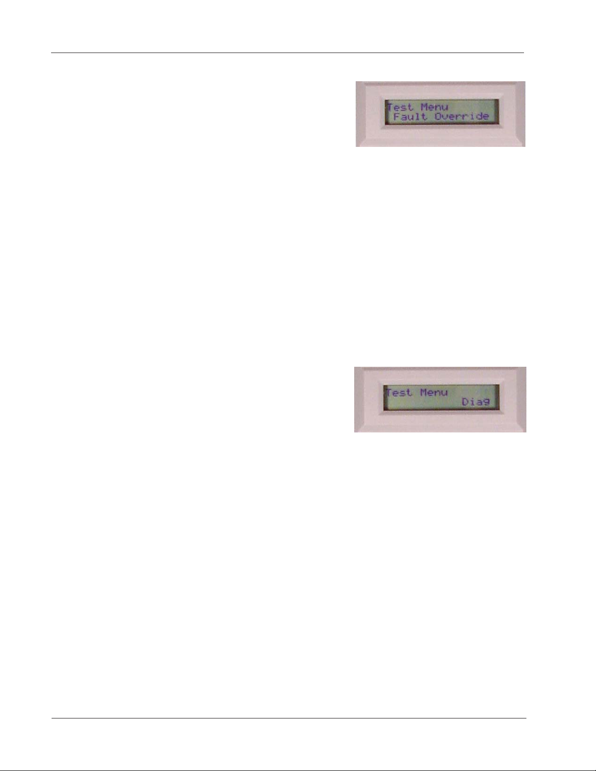
Test Menu ⇒ Fault Override
Fault Override Category
This category deals with the configuration of fault information from the
Engine Manager and the Control
Processor. If the option is set to On,
then the fault is overridden and won't
be reported on the panel. If the option
is set to Off, then the override is disabled and the fault is reported if it occurs.
Use the Arrow and Enter keys to select Menu => Test Menu => Fault Override to
get here.
Paper Motion
This parameter controls paper motion fault reporting status. This setting is
saved in NVRAM so that it does not need to be set up on powerup each time.
Automatic Paper Motion Fault Retry is a feature that has been implemented to
eliminate intermittent false paper motion faults. When a paper motion fault is
detected while printing is in progress, the paper is reversed approximately 3
inches, then moved forward again. If the paper motion fault persists, the
printer is placed offline and the fault is reported. This feature can eliminate
false paper motion faults caused by random electrical noise or paper chads/
dust that can be removed by the paper reversal.
Diag Category
This is a diagnostics and calibration
category. Use the Arrow and Enter keys
to select Menu => Test Menu => Diag to
get here.
Cal-Paper (Calibrate Paper Out)
This parameter allows users to calibrate the paper-out detection sensor if the
factory default settings fail to detect when the paper really is out, or when false
paper-out faults occur. Pressing Enter will initiate a series of messages instructing the operator to calibrate the detection sensor:
• Remove the paper from the printer, close the tractor door, and press
Enter. A numeric value will be displayed briefly. A new message appears
instructing the user to load the printer with paper.
• Press Enter. A new numeric value is displayed briefly, ending the calibration sequence.
3–68 Operator Manual
Page 69

Help Menu
Help Menu
There are no categories in this menu. Its purpose
is to allow the user to print out a list of all of the
selected options in a single report. See page 3-45
for how to do this.
This graphic summarizes navigation through the menus, categories, and options of the control panel.
Offline
ONLINE
OFFLINE
Online
Menu
Categories
Category
Parameters
Parameter
Settings
Navigations
within
Operator,
Config,
and Test
menus
MENU
CLEAR
ONLINE
OFFLINE
ONLINE
OFFLINE
CLEAR
ONLINE
OFFLINE
CLEAR
Operator
Menu
Arrow Keys
Config
Menu
Arrow Keys
Test
Menu
Arrow Keys
Help
Menu
Arrow Keys
Figure 3 - 5. Control Panel Navigation
Chapter 3: Printer Menus and the Control Panel 3–69
Page 70

Blank
Page
3–70 Operator Manual
Page 71

Appendix A: Troubleshooting
Introduction
This chapter deals with troubleshooting problems on a 6300 Series printer.
Messages that indicate printer faults and errors are explained and corrective
action given. The few paper handling and print quality problems that may
occur are also explained.
Messages
Messages on the Control Panel Display report both normal operation and fault
situations. In Table A-1 is presented a listing of the Display Messages that need
explanation or action on the part of the operator or repair person. Each
message listing includes causes and corrective actions where necessary.
Faults
When a fault occurs, it will cause the printer to cease operation and go Offline.
The printer alarm will sound, the Fault Indicator will illuminate, and the display
will report a fault message.
In some cases it is possible to clear an error message and continue using the
printer by depressing the Clear key. However, the quality of the print may be
questionable and collateral damage to other parts may result. If the fault
message returns, perform the required corrective action.
If a nondestructive fault occurs in the middle of printing a document, one line
of text may be lost after the error condition is corrected and the printer put
back Online.
If the fault is in the control panel or
interprocessor link, the fault message may not
be displayed, and the beeper and Fault LED
may not operate.
Fault Correction Procedure
Step 1. First check the fault message on
the Control Panel Display and look it up
in the Fault Message tables provided
here.
Step 2. Perform the required corrective
action. Some Fault and Error messages
will automatically clear as soon as the
problem is corrected (for example, the
Paper Out message will clear when a
new stack of paper is loaded).
Step 3. If a faulty piece of hardware is
indicated, call your Customer Service
Representative for repair.
Appendix A: Troubleshooting A–71
Page 72

Error Messages
Step 4. If any other faults appear on the display after you have corrected the
original problem, go back to Step 1 and perform required corrective actions
for the new problem. Otherwise place the printer back Online and test it
during normal print operations.
Table A - 1. Display Messages
MESSAGE Explanation and Corrective Action
ATTENTION Explanation:
Corrective Action:
Bad Packet Explanation:
Corrective Action:
Bad TWICO Int. Explanation:
Corrective Action:
Bad VFU Channel Explanation:
Corrective Action:
Bad VFU Count Explanation:
Corrective Action:
Buffer Overflow Explanation:
Corrective Action:
Chnl Not Found Explanation:
Corrective Action:
Ctrl Fault Explanation:
Corrective Action:
Ctrl Link Flt Explanation:
Corrective Action:
Data Overrun Explanation:
Corrective Action:
Font Dnld Error Explanation:
Corrective Action:
The host has sent the Bell Command.
Corrective action depends on the reason the Bell Command was sent.
Contact your system operator.
This message indicates that a fault has occurred in the communica-
tions between the I/O processor and the main processor.
Cycle power and try again. If the problem returns, remove and replace
the Engine Controller Board. If the problem returns, download new
printer firmware.
The Twinax PSIO is damaged or corrupted.
Cycle power and try again. If this does not clear the problem, remove
and replace the Twinax PSIO Assembly.
A VFU channel command has been received from the host requesting
an illegal channel.
1. Correct data from host and retransmit.
2. Ensure the integrity of the printer ground connection.
An incorrect number of bytes has been detected in a VFU download.
Correct data from host and retransmit.
A buffer overflow has been detected on the currently active host
interface. This is most likely caused by a host failure to respond to a
busy signal.
1. Ensure correct protocol has been selected.
2. Check wiring of I/O cable between host and printer. (See the
Applications Manual for a detailed explanation.)
VFU Channel requested by the host computer cannot be found.
1. Correct data from host, then retransmit it to the printer.
2. Ensure the integrity of the printer ground connection.
This message indicates that a fatal fault has occurred in the control
processor.
Call your Customer Service Representative for repair.
The Control Processor has detected a fault in the Main Processor to
Control Processor link.
Call your Customer Service Representative for repair.
A data overrun has been detected on the currently active host
interface. This is most likely caused by an incorrectly configured serial
baud rate, data bits, or parity.
Check setting on Serial Baud Rate, Data Bits, and Parity parameters
through the printer control panel.
An error has been detected uring a font download.
Correct data and retransmit from host.
A–72 Operator Manual
Page 73

Error Messages
Graphic Check Explanation:
Corrective Action:
HammerTime Explanation:
Corrective Action:
HammerVoltage1 Explanation:
Corrective Action:
HammerVoltage2 Explanation:
Corrective Action:
Heap Overflow Explanation:
Corrective Action:
Key Disabled Explanation:
Corrective Action:
Lost Adrs (27) Explanation:
Corrective Action:
Lost Sync (28) Explanation:
Corrective Action:
No VFU Loaded Explanation:
Corrective Action:
NVRAM Fault Explanation:
Corrective Action:
This message indicates that the printer has received an unprintable
graphic. This message only appears if the Set Graphic Error Action
Command has been set properly.
Clear the message (Clear key), then place the printer back Online.
Confirm with host why Graphic check message was sent.
The software controlling the print hammer timing has detected an
internal inconsistency.
Press the Clear key. If it faults repeatedly, call your Customer Service
Representative and skip to the next print job.
One of the hammer drive circuits was turned on when it shouldn’t
have been, so all printing has been disabled. The usual cause is a
failed drive transistor.
Call your Customer Service Representative for repair.
A high resistance coil fault has likely occurred in one or more of the
hammer coils. Note: this fault message will have been preceded by
printing slow-down attempts associated with On-The-Fly thermal
monitoring of hammer bank temperature.
Check the hammer bank for defective coils. Confirm that the hammer
driver board is functioning properly. Replace the hammer driver
board. Call your Customer Service Representative for repair.
Graphics memory space is full and the printer cannot accept or
process data. Printer will reset and data will be lost.
Insert line terminators in data stream so the printer will process the
data, then retransmit the data.
Key has no function for this printer model or mode of operation.
No corrective action.
Certain communication signals have been lost between the printer
and the host computer.
Check cable connection, setup of host, and printer address setting.
The host is not communicating with the printer.
Verify address of computer and host setup. Check I/O cables.
When this message is displayed during printer installation, you may
continue to test the printer by placing the printer Offline and entering
Menu mode to select print tests or calibration routines.
A VFU command was received from the host before a VFU was
downloaded.
Download the required VFU information, then retransmit the data.
The nonvolatile data checksum has failed because of one of the
following conditions:
(1) A new RAM has been installed.
(2) New software with different nonvolatile variables has been
installed.
(3) The variable values have been altered in a destructive manner.
Depress the Clear key. If the message does not clear, cycle printer
power. If the message still does not clear, call your Customer Service
Representative for repair.
Appendix A: Troubleshooting A–73
Page 74

Error Messages
Offline Data In Explanation:
Corrective Action:
Offline Dump On Explanation:
Corrective Action:
Online Download Explanation:
Corrective Action:
Online Dump On Explanation:
Corrective Action:
Overflow VFU Explanation:
Corrective Action:
Paper Motion Flt Explanation:
Corrective Action:
Paper Out Explanation:
Corrective Action:
Parity Error Explanation:
Corrective Action:
Print Fault Explanation:
Corrective Action:
Replace Rbn Explanation:
Corrective Action:
The printer is in Offline condition and nonprinted data is in the buffer.
There is no corrective action required. Under normal conditions, the
printer continues to print when it is placed back Online. If you do not
want the buffered data to print, enter the Clear menu by depressing the
Clear key before going back Online and select the Clear Buffers entry to
clear the buffered data.
The printer is in Offline condition and Dump Mode is enabled.
No corrective action is necessary. Place the printer back Online when
you are ready to print.
The printer is receiving downloaded fonts or VFU information.
This message will clear when the download is complete.
The printer is ready to accept and print data from the host through
Dump Mode. All data received from the host will be printed in hexadeci-
mal format.
No corrective action is required.
An excessive number of bytes has been sent by the host in a VFU
download.
Correct data and retransmit from host.
The control processor has detected that the paper has failed to move the
required distance after sending a command to the Paper Drive Motor.
Check for paper feed problems. If there are any paper feed problems,
correct them, then press the Clear key to clear the fault. If there are no
paper feed problems and the condition does not clear, call your Cus-
tomer Service Representative.
Paper is not being detected by the Paper Out sensor.
If this message is correct, refer to the Paper Loading sections in Chapter
2, then load paper. If the fault does not clear, call your Customer Service
Representative for repair.
Parity is enabled and a mismatch on Bit 8, between the computer and
the printer, has been detected on the currently active host interface.
If there is a mismatch between the setting of the printer and the setting
of the host, you can change printer parity. See the Config Menu section
in Chapter 3.
If there is no mismatch between the printer and host settings, then the
data sent from the host has been corrupted. Retransmit the data from
the host. If the condition repeats, set up the printer for Dump Mode (see
the Config Menu section in Chapter 3), and retransmit the data again. If
you find no errors in the Dump Mode data, call your Customer Service
Representative for repair.
Faulty communication between the main and control processor has
occurred causing a dot row to misprint. The printer automatically
recovers from this condition.
Under normal circumstances there is no corrective action other than to
depress the Clear key to remove the fault message from the display. If,
however, this problem persists, call your Customer Service Representa-
tive for repair.
Caused when Rbn Monitor has reached its set level.
Check/Replace the ribbon then reset the Rbn Monitor.
A–74 Operator Manual
Page 75

Error Messages
Ribbon Fault Explanation:
Corrective Action:
Setup Address Explanation:
Corrective Action:
Shuttle Fault Explanation:
Corrective Action:
Testing Hardware Explanation:
Corrective Action:
The Ribbon Fault Detector is not reading any movement in the printer
ink-ribbon.
Depress the Clear key and try to print again. If the fault returns, try to
turn the Ribbon Knob. If the Ribbon Knob will not turn, check to see if
the ribbon is caught on the hammer bank or one of the other mecha-
nisms through which the ribbon moves. If the Ribbon Knob does not
turn and the ribbon is not caught somewhere, install a new ribbon
cartridge. Another possible cause of this error is a print gap that is too
tight. Increase the print gap by using the “+” Print Gap key or rerun a
print gap operation using the Detect parameter (Operator Menu =>
Print Gap => Detect). If the Ribbon Knob turns and the print gap is fine
and the fault does not clear, call your Customer Service Representative for repair.
The printer address has not been set up or a configuration with
address set to UNDEFIN has been loaded.
Set up the printer address using the multilevel menus on the printer.
See the Config Menu in Chapter 3.
If the control processor detects the shuttle operating either above or
below the proper frequency, it shuts down the shuttle and attempts to
restart it. If the shuttle still operates incorrectly after three consecutive
attempts, the Control Processor goes Offline, and the Shuttle Fault
message is displayed.
Depress the Clear key, then put the printer back Online. If this doesn’t
work, turn the power switch off, then back on again. Another possible
cause of this error is a print gap that is too tight. Increase the print gap
by using the “+” Print Gap key or rerun a print gap operation using the
Detect parameter (Operator Menu => Print Gap => Detect). If the error
condition persists after performing the above actions, call your
Customer Service Representative for repair.
The printer is performing internal diagnostic tests when the printer is
powered up.
If this message does not clear after a few seconds, then the Main CPU
is dead. Under normal circumstances there is no corrective action. If
the message does not clear automatically, call your Customer Service
Representative for repair.
Appendix A: Troubleshooting A–75
Page 76

Paper Problems
Table A - 2. Paper/Printing Corrective Action
Problem
The paper holes are wider
than normal after passing
through the tractors.
Printed characters on
heavyweight or multi-part
paper are smeared.
The printed characters are
too light.
The printed characters are
shaky.
Cause
Horizontal paper tension is
too tight.
The Print Gap is too tight. Increase the Print Gap by using
The Print Gap is too loose or
the ribbon is worn out.
The Print Gap is not set
correctly.
Unlock and readjust the tractors
so that the paper holes line up
evenly with the tractor pins.
the “+” Print Gap key or rerun a
print gap operation using the
Detect parameter (Operator
Menu => Print Gap => Detect).
Decrease the Print Gap by using
the “-” Print Gap key or rerun a
print gap operation using the
Detect parameter (Operator
Menu => Print Gap => Detect).
If this does not correct the
problem, replace the ribbon
cartridge with a new one.
Adjust the Print Gap by using
the “+” or “-” Print Gap keys or
rerun a print gap operation
using the Detect parameter
(Operator Menu => Print Gap
=> Detect).
Corrective Action
The paper comes out of the
tractors or the paper tears at
the right or left holes along
the edges.
A–76 Operator Manual
(1) The horizontal paper
tension is incorrect.
(2) The Print Gap is too tight.
(1) Unlock and readjust the
right tractor so the paper holes
line up evenly with the tractor
pins.
(2) Increase the Print Gap by
using the “+” Print Gap key or
rerun a print gap operation
using the Detect parameter
(Operator Menu => Print Gap
=> Detect).
Page 77

Appendix B: Specifications
Industry and Agency Standards
The 2900 printer is designed to meet the requirements of several industry and
government agency standards.
Electro-Magnetic Emissions
EMI: FCC part 15, subpart J, Class A and EN55022 Class B
Harmonics: EN 61000-3-2
Flicker: EN 61000-3-3
Electro-Magnetic Immunity
ESD: EN 61000-4-2
RF EMF: EN 61000-4-3
EFT/B: EN 61000-4-4
Surge: EN 61000-4-5
RF CM: EN 61000-4-6
PF MF: EN 61000-4-8
V Dips/Int: EN 61000-4-11
Energy Conservation
ENERGY STAR® compliant
Safety
IEC 60950:1991 plus Amendment 1, 2, 3, and 4, and National Deviations AT,
AU, BE, CA, CH, CZ, DE, DK, ES, FI, FR, GB, GR, HU, IE, IT, JP, KR, NL, NO,
SE, SG, SL, US and Group Differences per CB Bulletin 94AI (Mar 99).
ANSI UL 1990-95, CAN/CSA-C22.2 No. 950-95, and EN6950:1992, including
Amd 1, 2, 3, and 4 safety requirements.
Acoustic
ISO 7779:1988(E)
ISO 9296:1988(E)
Marking
The printer complies with the CE mark requirements, per European norms.
Appendix B: Specifications B–77
Page 78

Industry and Agency Standards
Physical Configurations
Weight
115.4 lbs.
Dimensions
Width: 28.3 inches
Height: 13.0 inches
Depth: 14.4 inches
Depth with paper exit guide assembly: 23.4 inches
Preventive Maintenance
This printer is designed to eliminate the requirement of scheduled maintenance procedures, such as alignment, adjustment, or lubrication. Preventive
maintenance is limited to periodic cleaning. Dust and paper fibers should be
removed periodically with a soft cloth and brush or a vacuum cleaner. Clean
the printer case with a damp cloth and soapy water. DO NOT use any abrasive
cleaners or solvents, as they will damage the case.
Environment
Operating
Temperature (Dry Bulb): 50°F to 104°F (10°C to 40°C)
Humidity: 10 to 90% noncondensing with a maximum wet bulb
Altitude: To 8,000 ft. (2438 meters)
Nonoperating
Temperature:
Humidity: 10 to 95% noncondensing
Altitude: To 10,000 ft. (3048 meters)
Thermal Shock: 61°F (20°C) per hour
Vibration: Units meet NSTA (National Safe Transit Association)
temperature of 82°F (28°C) and a minimum dew point of
36°F (2°C )
Boxed: -40°F to 151°F (-40°C to 66°C)
Unboxed: 14°F to 122°F (-10°C to 50°C)
requirements.
Safety
Personnel hazard areas have restricted access with appropriate warning labels.
Catastrophic equipment failures are inhibited with protective functions in
major areas of overload potential.
B–78 Operator Manual
Page 79

Cooling System
Cooling system malfunctions are detected and a failure will result in shuttle
motion, paper motion, and printing functions being inhibited. The malfunction Hammer Voltage1 will be reported on the control panel display.
Acoustics
The Sound Power Level is a 9 position average, per ISO 7779. The Sound
Pressure Level is a 4 position average, per ISO 9296.
Sound Pressure Level Sound Power Level
55 dB(A) 7.0 Bel
Power Supply
The printer requires single phase, 47 to 63 Hz. 90 to 264 VAC input power. The
printer’s universal power supply automatically adjusts to the correct values. A
fuse is provided to interrupt power to the power supply. The following table
gives typical current values.
2900 Current/Wattage Requirements @ Nominal Voltage
Environment
AC Volts Freq. Average Peak AverageAverage
(RMS) (Hz) Operating Operating Idle (<5 min.) Idle (>5 min.)
110 50 1.0 A/055 W 2.3 A/250 W 0.3 A/35 W 0.2 A/19 W
110 60 1.0 A/105W 2.3 A/250W 0.3 A/35W 0.2 A/19 W
220 50 0.5 A/105W 1.2 A/250W 0.2 A/35W 0.1 A/19W
Heat Load Contribution
The average heat load contribution to the environment is approximately 735
BTUs per hour (215 Watts). The minimum heat load contribution is approximately 100 BTUs per hour (30 watts). The maximum is 2050 BTUs per hour
(600 Watts), under continuous full-load printing conditions.
Printing Conditions (110 VAC/60 Hz) Wattage
BTU/Hr
Power On, not printing 55 W 188
100% Uppercase Rolling ASCII 400W 1370
Black Page Plot 600 W 2050
Appendix B: Specifications B–79
Page 80

Emulations and Fonts
Emulations
Emulations available on the 2900 Series:
Epson DFX-9000, IBM Proprinter III XL, MTPL
Characters Per Inch
Seven basic Characters Per Inch (CPI) settings are available through the Control Panel. They include 10, 12, 13.33, 15, 16.67, 17.14, and 20. These character
matrices can be doubled to produce 5, 6, 6.67, 7.5, 8.33, and 8.57 CPI. In some
emulations the availability of certain CPIs is restricted. Some emulations provide
proportional spacing and justification features.
Lines Per Inch
Ten Lines Per Inch (LPI) settings are available through the Control Panel.
They include 1.5, 2, 3, 4, 5, 6, 8, 9, 10, and 12 LPI. In some emulations the
availability of certain LPIs is restricted. Some emulations provide variable line
spacing.
Type Styles
There are six resident type styles available on your printer. They include Draft,
Data Processing (DP), Gothic, Courier, OCR-A, and OCR-B. All type styles and
the two output modes (for Draft and DP) are selectable through the printer
control panel.
Draft and Data Processing
Draft and Data Processing type styles print in two modes: Constant Density
Fonts (CDF) and Enhanced.
Constant Density Fonts print at the same dot density regardless of the CPI. This
produces consistent print speed even when changing from one CPI to another.
Enhanced Mode provides higher resolution and a greater range of CPIs than
CDF Mode. Because Enhanced Mode uses a variety of dot densities you should
expect a change in print speed of text when switching from one CPI to another.
Gothic and Courier
These two type styles provide Near Letter Quality (NLQ) printing. They print at
higher dot densities and use denser character matrixes for greater readability.
OCR–A and OCR–B
These print at 10 CPI only, mostly for Optical Character Recognition applications. There are three possible OCR-A densities: Standard, Enhanced, and High
Density. OCR-B always prints at High Density.
Large Character Printing
In certain emulations, large character printing is available. These characters are
printed using the TallyGenicom MonoBlock Bold TrueType font. This is a
monospaced san-serif font.
B–80 Operator Manual
Page 81

Fonts, Languages and Characters
Standard Languages and Character Sets
There are two ways to select a language or character set.
One method is by substituting certain characters in the lower half of the character set, such as # $ @ [ \ ] ^ ` { | } and ~. This can be done by using the control
panel Language selection, or through the emulation. The language substitutions available through the emulation differ by emulation.
The other method is by selecting an entire set of the characters (also called
code pages) for the upper half of the character set. This can be done by using
the control panel Character Set selection, or through the emulation. The
character sets available through the emulation differ by emulation.
Language substitutions and character set selections are valid for all font styles
except OCR-A and OCR-B. In the case of OCR-A and OCR-B, the only available
options are DIN and ANSI, selected through the OCR Style selection on the
control panel.
Language Substitutions
There are 42 available language substitutions, including Canadian, Canadian
Alternate, Chinese, Danish MT660, Danish 2 Epson, Dutch LG, Finnish LG,
French (ISO 69), French Epson, French MT660, French Withdrawn, German
(ISO 21), Hebrew LG, Hungarian, International Reference Version (ISO 2),
Italian (ISO 15), Italian Epson, Italian MT660, Japanese (ISO 14), JIS Roman
LG, Latin American Epson, Norwegian Epson, Norwegian / Danish (ISO 60),
Norwegian / Danish Epson, Norwegian / Danish ISO LG, Norwegian / Danish
LG, Norwegian / Danish MT660, Portuguese (ISO 16), Portuguese LG, Spanish
(ISO 17), Spanish Epson, Swedish LG, Swedish / Finnish (ISO 11), Swedish /
Finnish Basic (ISO 10), Swedish / Finnish MT660, Swiss LG, Turkish LG, UK
(ISO 4), UK Epson, UK LG, US (ISO 6), and VT100.
Character Sets
There are 40 available character sets / code pages, including Bulgarian (Code
Page 866B), Cyrillic (Code Page 866), Cyrillic (Code Page 1251), Cyrillic (ISO
8859-5), DEC Greek Supplemental, DEC Hebrew Supplemental, DEC Multinational, DEC Supplemental, DEC Technical, DEC Turkish Supplemental, French
Canadian (Code Page 863), Greek (Code Page 437G), Greek (Code Page 851),
Greek (Code Page 869), Greek (Code Page 928), Greek (Code Page 1253),
Greek (ISO 8859-7), Hebrew (Code Page 862), Hebrew (Code Page (1255),
Hebrew (ISO 8859-8), IBM Proprinter (Code Page 437), Katakana (ISO 13),
Latin 1 (Code Page 850), Latin 1 (Code Page 1252), Latin 1 (ISO 8859-1),
Latin 2 (Code Page 852), Latin 2 (Code Page 1250), Latin 2 (ISO 8859-2),
Latin 9 (ISO 8859-15), Line Draw (MT660), Roman-8 (HP), Russian Cyrillic
(Code Page 855), SAP 8859-1, SAP 8859-2, SAP 8859-5, Turkish (Code Page
857), Turkish (Code Page 1254), Turkish (DEC), Turkish (ISO 8859-9), and
Turkish (Siemens).
Appendix B: Specifications B–81
Page 82

Configurations, Paper and Speed
Nonvolatile Memory
Your printer stores up to 10 printer configurations in nonvolatile memory.
Paper Description
The printer uses continuous, sprocket-fed type paper, 2.5 inches (64 mm) to 18
inches (457 mm) outside width and 3.0 inches (76 mm) to 12.0 inches (305
mm) in length. One- to six-part paper may be used with a maximum thickness
of .025 inches (0.64 mm). (Reference specifications: ISO 2784, DIN 9771 and
DIN 6721.)
Paper Movement Speed
The default paper slew speed is 25 IPS. If the Fast Slew control panel option is
enabled, the slew speed is 36 IPS unless heavy forms are detected based on the
print gap setting, in which case the slew speed is automatically reduced to 31
IPS.
Throughput
Maximum Print Speed - Character per Second 1630
Graphics Throughput - Inches per Minute
60 X 48 75
60 X 72 50
120 X 72 DPI 25
ECMA 132 - Pages Per Hour
#2 Letter Performance 10 CPI Draft 825
#3 Letter Performance 10 CPI NLQ 252
#4 Letter Endurance 10 CPI NLQ 252
#5 Spreadsheet Perf. 17 CPI Draft 983
#6a Spreadsheet Perf. 17 CPI Draft 983
#6b Spreadsheet Perf. 17 CPI NLQ 342
#7 Graphics Performance 573
B–82 Operator Manual
Page 83

Blank
Page
Appendix B: Specifications B–83
Page 84

4500 Daly Drive, Suite 100 T 703.833.8700
255069-001A
Chantilly, VA 20151 F 703.222.7629
www.tallygenicom.com
 Loading...