

Page 1

User Guide 7006 7008 Thermal Printer
Page 2

Page 3

Table of Contents
TOC-1
Table of Contents
Welcome . . . . . . . . . . . . . . . . . . . . . . . . . . . . . . . . . . . . . . . . . . . . . .1-1
Getting Started . . . . . . . . . . . . . . . . . . . . . . . . . . . . . . . . . . . . . . . .2-1
Parts and Functions . . . . . . . . . . . . . . . . . . . . . . . . . . . . . . . . . . . . . . . . . 2-1
Outside the Printer . . . . . . . . . . . . . . . . . . . . . . . . . . . . . . . . . . . . . . . . . . . 2-1
Inside the Printer . . . . . . . . . . . . . . . . . . . . . . . . . . . . . . . . . . . . . . . . . . . . . 2-3
Paper Media Guide Bar . . . . . . . . . . . . . . . . . . . . . . . . . . . . . . . . . . . . . . . . 2-4
Connection Ports and Power Connector. . . . . . . . . . . . . . . . . . . . . . . . . . . 2-5
Take Up Spindle and Take Up Clutch (Gears) . . . . . . . . . . . . . . . . . . . . . . . 2-6
Supply Spindle and Supply Clutch. . . . . . . . . . . . . . . . . . . . . . . . . . . . . . . . 2-6
Printhead Assembly (TPH, Shield, Bracket, and LED Array) . . . . . . . . . . . . 2-7
Platen and Index Sensor. . . . . . . . . . . . . . . . . . . . . . . . . . . . . . . . . . . . . . 2-7
Understanding the Control Panel Buttons and the LCD (7008 only) . . 2-8
Understanding the LCD Menu Structure . . . . . . . . . . . . . . . . . . . . . . . . . 2-10
Setting Up the Printer . . . . . . . . . . . . . . . . . . . . . . . . . . . . . . . . . . . . . . 2-12
Printer Requirements . . . . . . . . . . . . . . . . . . . . . . . . . . . . . . . . . . . . . . . . 2-12
Unpacking the Printer . . . . . . . . . . . . . . . . . . . . . . . . . . . . . . . . . . . . . . . . 2-13
Controls, Indicators, and Connectors . . . . . . . . . . . . . . . . . . . . . . . . . . . . 2-14
Connecting Data Cables to the Printer . . . . . . . . . . . . . . . . . . . . . . . . . . . 2-15
USB-A HOST Connectivity . . . . . . . . . . . . . . . . . . . . . . . . . . . . . . . . . . . . 2-16
Connecting Power to the Printer. . . . . . . . . . . . . . . . . . . . . . . . . . . . . . . . 2-17
Printer Power Test . . . . . . . . . . . . . . . . . . . . . . . . . . . . . . . . . . . . . . . . . . 2-20
Thermal Transfer Ribbon Loading (TT Printers Only) . . . . . . . . . . . . . . . . 2-22
Loading Media. . . . . . . . . . . . . . . . . . . . . . . . . . . . . . . . . . . . . . . . . . . . . . 2-32
Loading Large Roll OD Media . . . . . . . . . . . . . . . . . . . . . . . . . . . . . . . . . . 2-41
Performing the Self Test . . . . . . . . . . . . . . . . . . . . . . . . . . . . . . . . . . . . 2-44
Software Installation . . . . . . . . . . . . . . . . . . . . . . . . . . . . . . . . . . . .3-1
METHOD A: Install Software Using the Installation CD . . . . . . . . . . . . 3-1
METHOD B: Install Software Using the Web Site . . . . . . . . . . . . . . . . . 3-1
Page 4

Table of Contents
TOC-2
Windows Driver Installation . . . . . . . . . . . . . . . . . . . . . . . . . . . . . . . . . . 3-2
Setting Printing Preferences . . . . . . . . . . . . . . . . . . . . . . . . . . . . . . . . . . . . 3-2
Installing and Running the Administrator Software . . . . . . . . . . . . . . . 3-3
Installing the Administrator Configuration Software . . . . . . . . . . . . . . . . . . 3-3
Using the Administrator Tool. . . . . . . . . . . . . . . . . . . . . . . . . . . . .4-1
Administrator Sections . . . . . . . . . . . . . . . . . . . . . . . . . . . . . . . . . . . . . . 4-2
I/O Settings . . . . . . . . . . . . . . . . . . . . . . . . . . . . . . . . . . . . . . . . . . . . . . . . . 4-2
Printer Settings . . . . . . . . . . . . . . . . . . . . . . . . . . . . . . . . . . . . . . . . . . . . . . 4-2
Calibrating the Printer . . . . . . . . . . . . . . . . . . . . . . . . . . . . . . . . . . . . . . . . . 4-2
Method 1: Calibrate using the Administrator configuration software. 4-3
Method 2: Calibrate by Performing a Self Test. . . . . . . . . . . . . . . . . . 4-3
Method 3: Calibrate Using the Programming Language (CPL) . . . . . . 4-3
Advanced Printer Settings. . . . . . . . . . . . . . . . . . . . . . . . . . . . . . . . . . . . . . 4-3
Fonts/Objects . . . . . . . . . . . . . . . . . . . . . . . . . . . . . . . . . . . . . . . . . . . . . . . 4-4
Profile Management . . . . . . . . . . . . . . . . . . . . . . . . . . . . . . . . . . . . . . . . . . 4-4
Firmware Upgrade . . . . . . . . . . . . . . . . . . . . . . . . . . . . . . . . . . . . . . . . . . . 4-4
PCL Windowing . . . . . . . . . . . . . . . . . . . . . . . . . . . . . . . . . . . . . . . . . . . . . 4-5
CPL Editor . . . . . . . . . . . . . . . . . . . . . . . . . . . . . . . . . . . . . . . . . . . . . . . . . . 4-6
USB A Host. . . . . . . . . . . . . . . . . . . . . . . . . . . . . . . . . . . . . . . . . . . .5-1
Loading Firmware Using a USB Flash Drive . . . . . . . . . . . . . . . . . . . . . 5-1
Loading firmware using the USB A Host . . . . . . . . . . . . . . . . . . . . . . . . 5-2
. . . . . . . . . . . . . . . . . . . . . . . . . . . . . . . . . . . . . . . . . . . . . . . . . . . . . . . . . . 5-2
Network Printing . . . . . . . . . . . . . . . . . . . . . . . . . . . . . . . . . . . . . . .6-1
Assigning a Static Address . . . . . . . . . . . . . . . . . . . . . . . . . . . . . . . . . . . 6-1
Using Automatic Address Assignment. . . . . . . . . . . . . . . . . . . . . . . . . . 6-2
Verifying Network Settings . . . . . . . . . . . . . . . . . . . . . . . . . . . . . . . . . . . 6-3
Configuring a Printer Driver for Network Use . . . . . . . . . . . . . . . . . . . . 6-4
Sharing the Printer on a Network . . . . . . . . . . . . . . . . . . . . . . . . . . . . . . 6-6
Network Support Materials . . . . . . . . . . . . . . . . . . . . . . . . . . . . . . . . . . . 6-6
Page 5

Table of Contents
TOC-3
Printing Standard Labels and Tags . . . . . . . . . . . . . . . . . . . . . . . .7-1
Using CPL Programming . . . . . . . . . . . . . . . . . . . . . . . . . . . . . . . . . . . . . 7-1
Using Third-Party and Proprietary Applications . . . . . . . . . . . . . . . . . . 7-3
Printing from Microsoft Word . . . . . . . . . . . . . . . . . . . . . . . . . . . . . . . . . . . 7-3
To Configure the Software for the Printer. . . . . . . . . . . . . . . . . . . . . . . . . . 7-3
Setting Label Size . . . . . . . . . . . . . . . . . . . . . . . . . . . . . . . . . . . . . . . . . . . . 7-5
Creating a Label and Barcode . . . . . . . . . . . . . . . . . . . . . . . . . . . . . . . . . . . 7-8
Printing a Label . . . . . . . . . . . . . . . . . . . . . . . . . . . . . . . . . . . . . . . . . . . . . . 7-8
Printing from Proprietary Applications. . . . . . . . . . . . . . . . . . . . . . . . . . . . . 7-9
Troubleshooting. . . . . . . . . . . . . . . . . . . . . . . . . . . . . . . . . . . . . . . .8-1
Isolating Problems . . . . . . . . . . . . . . . . . . . . . . . . . . . . . . . . . . . . . . . . . . 8-1
Run a Printer Self Test . . . . . . . . . . . . . . . . . . . . . . . . . . . . . . . . . . . . . . . . 8-1
Print a Proven Label Format . . . . . . . . . . . . . . . . . . . . . . . . . . . . . . . . . . . . 8-1
Print a New Label Format . . . . . . . . . . . . . . . . . . . . . . . . . . . . . . . . . . . . . . 8-2
Check the Label Format Header Line . . . . . . . . . . . . . . . . . . . . . . . . . . . . . 8-2
“Comment Out” Portions of the Non-Working Label Format. . . . . . . . . . . 8-2
Common Issues. . . . . . . . . . . . . . . . . . . . . . . . . . . . . . . . . . . . . . . . . . . . . 8-3
Labels Skipping or Printer Feeding Blank Labels . . . . . . . . . . . . . . . . . . . . 8-3
READY Light is Red . . . . . . . . . . . . . . . . . . . . . . . . . . . . . . . . . . . . . . . . . . 8-3
Printer Drivers . . . . . . . . . . . . . . . . . . . . . . . . . . . . . . . . . . . . . . . . . . . . . . . 8-3
Setting Up an Ethernet Printer . . . . . . . . . . . . . . . . . . . . . . . . . . . . . . . . . . 8-3
Serial Communication . . . . . . . . . . . . . . . . . . . . . . . . . . . . . . . . . . . . . . . . . 8-4
Parallel Communication. . . . . . . . . . . . . . . . . . . . . . . . . . . . . . . . . . . . . . . . 8-4
Printing Too Light . . . . . . . . . . . . . . . . . . . . . . . . . . . . . . . . . . . . . . . . . . . . 8-5
General Troubleshooting Tips . . . . . . . . . . . . . . . . . . . . . . . . . . . . . . . . . 8-5
Equipment and Cabling . . . . . . . . . . . . . . . . . . . . . . . . . . . . . . . . . . . . . . . . 8-5
Printing a Diagnostic or Self Test Page . . . . . . . . . . . . . . . . . . . . . . . . . . . . 8-5
Cleaning the Printhead . . . . . . . . . . . . . . . . . . . . . . . . . . . . . . . . . . . . . . . . 8-5
Paper is Jammed in the Printer. . . . . . . . . . . . . . . . . . . . . . . . . . . . . . . . . . 8-6
Tips for Avoiding Paper Jams . . . . . . . . . . . . . . . . . . . . . . . . . . . . . . . . . . . 8-6
Blank Label is Printing . . . . . . . . . . . . . . . . . . . . . . . . . . . . . . . . . . . . . . . . . 8-6
Page 6

Table of Contents
TOC-4
Printer Specifications . . . . . . . . . . . . . . . . . . . . . . . . . . . . . . . . . . .9-1
Technical Specification Information . . . . . . . . . . . . . . . . . . . . . . . . . . . . 9-1
Standard Features . . . . . . . . . . . . . . . . . . . . . . . . . . . . . . . . . . . . . . . . . . . . 9-1
Optional Features . . . . . . . . . . . . . . . . . . . . . . . . . . . . . . . . . . . . . . . . . . . . 9-2
Printing Specifications. . . . . . . . . . . . . . . . . . . . . . . . . . . . . . . . . . . . . . . . . 9-2
Media Specifications . . . . . . . . . . . . . . . . . . . . . . . . . . . . . . . . . . . . . . . . . . 9-3
Media Indexing . . . . . . . . . . . . . . . . . . . . . . . . . . . . . . . . . . . . . . . . . . . . . . 9-3
Ribbon Specifications . . . . . . . . . . . . . . . . . . . . . . . . . . . . . . . . . . . . . . . . . 9-4
Label Roll Changes per Ribbon . . . . . . . . . . . . . . . . . . . . . . . . . . . . . . . . . . 9-4
Font Specifications . . . . . . . . . . . . . . . . . . . . . . . . . . . . . . . . . . . . . . . . . . . 9-4
Bar Code Symbologies and Specifications . . . . . . . . . . . . . . . . . . . . . . . . . 9-5
Programming Language (CPL) . . . . . . . . . . . . . . . . . . . . . . . . . . . . . . . . . . 9-5
Communications Specifications . . . . . . . . . . . . . . . . . . . . . . . . . . . . . . . . . 9-6
Electrical Specifications. . . . . . . . . . . . . . . . . . . . . . . . . . . . . . . . . . . . . . . . 9-6
International Environment Compliance . . . . . . . . . . . . . . . . . . . . . . . . . . . . 9-6
International Regulatory Compliance . . . . . . . . . . . . . . . . . . . . . . . . . . . . . 9-6
Environmental Specifications . . . . . . . . . . . . . . . . . . . . . . . . . . . . . . . . . . . 9-6
Physical Specifications . . . . . . . . . . . . . . . . . . . . . . . . . . . . . . . . . . . . . . . . 9-7
Software . . . . . . . . . . . . . . . . . . . . . . . . . . . . . . . . . . . . . . . . . . . . . . . . . . . 9-7
Preventive Maintenance . . . . . . . . . . . . . . . . . . . . . . . . . . . . . . . . . . . . . . . 9-7
Cleaning . . . . . . . . . . . . . . . . . . . . . . . . . . . . . . . . . . . . . . . . . . . . . . . . . . . 9-7
Consumables . . . . . . . . . . . . . . . . . . . . . . . . . . . . . . . . . . . . . . . . .10-1
Compatible Media. . . . . . . . . . . . . . . . . . . . . . . . . . . . . . . . . . . . . . . . . . 10-1
Consumables . . . . . . . . . . . . . . . . . . . . . . . . . . . . . . . . . . . . . . . . . . . . . . 10-1
TT Butterfly Labels . . . . . . . . . . . . . . . . . . . . . . . . . . . . . . . . . . . . . . . . . . 10-6
DT Rattail Labels . . . . . . . . . . . . . . . . . . . . . . . . . . . . . . . . . . . . . . . . . . . . 10-7
TT Rattail Labels . . . . . . . . . . . . . . . . . . . . . . . . . . . . . . . . . . . . . . . . . . . . 10-7
DT Non-Adhesive Tags . . . . . . . . . . . . . . . . . . . . . . . . . . . . . . . . . . . . . . . 10-8
TT Non-Adhesive Tags . . . . . . . . . . . . . . . . . . . . . . . . . . . . . . . . . . . . . . . 10-8
Metric Labels . . . . . . . . . . . . . . . . . . . . . . . . . . . . . . . . . . . . . . . . . . . . . . 10-9
Ribbons . . . . . . . . . . . . . . . . . . . . . . . . . . . . . . . . . . . . . . . . . . . . . . . . . . 10-11
Options. . . . . . . . . . . . . . . . . . . . . . . . . . . . . . . . . . . . . . . . . . . . . . . . . . 10-12
Page 7

Table of Contents
TOC-5
Cleaning and Preventive Maintenance . . . . . . . . . . . . . . . . . . . .11-1
Cleaning Instructions . . . . . . . . . . . . . . . . . . . . . . . . . . . . . . . . . . . . . . . 11-1
Printhead Assembly Removal and Replacement . . . . . . . . . . . . . . . . . 11-3
Printhead Assembly Removal . . . . . . . . . . . . . . . . . . . . . . . . . . . . . . . . . . 11-3
Printhead Assembly Replacement . . . . . . . . . . . . . . . . . . . . . . . . . . . . . . 11-5
Platen Assembly Removal and Replacement. . . . . . . . . . . . . . . . . . . . 11-8
Platen Assembly Removal . . . . . . . . . . . . . . . . . . . . . . . . . . . . . . . . . . . . 11-8
Platen Assembly Replacement . . . . . . . . . . . . . . . . . . . . . . . . . . . . . . . . 11-12
Index . . . . . . . . . . . . . . . . . . . . . . . . . . . . . . . . . . . . . . . . . . . . . . . . .1-1
Page 8

Page 9

1-1
Chapter
1
Welcome
Congratulations on the purchase of this thermal label printer. With its 2-year warranty,
mid-range performance, and customer service, the printer will provide you continuous
label printing with very little downtime and at the highest quality. Tally Dascom is committed to providing a high-performance and reliable user experience. This User’s Manual
provides information on how to install the printer and includes all necessary user support
information.
The following list of the documentation is located on the Installation CD, which ships
with every printer.
World Wide Web — Visit http://jadmin.dascom.com to download the latest firmware,
the current printer drivers, or to download or view documentation support.
Quick Start Guide — The Quick Start Guide provides illustrated high-level printer
setup information including media loading, ribbon loading for thermal transfer models,
and software/drivers installation instructions. A printed copy of this document is provided with every printer. Chapter 2, “Getting Started”, of this User’s Guide provides further instructions on setting up your printer.
Programmer’s Guide — The Programmer’s Guide provides information about how to
program all printer models. For up-to-date firmware release notes and to download the
most recent firmware required for the printers visit:
http://jadmin.dascom.com
Ethernet Printer Information — The Ethernet Printer Information provides information for configuring and troubleshooting the internal Ethernet print server. The Ethernet
Printer Information is a section of the Programmer’s Guide.
Printer Drivers (Microsoft Windows® only) — Printer drivers required for the printer
are provided on the Installation CD which ships with the printer. The latest drivers can
also be found on Tally Dascom's web site http://jadmin.dascom.com. Full instructions on
how to load these drivers are located in Chapter 3, “Software Installation”, of this User’s
Guide.
Marketing and Sales Support – The Tally Dascom web site has additional information
and sales support such as product brochures, presentations, and product images. The
files are available in many formats for easy-to-use downloads.
Page 10

Welcome
1-2
Technical Support — For technical support please contact your dealer or the Technical
Support Team of your Tally Dascom Representatives – see last page of this manual.
Page 11

2-1
Chapter
2
Getting Started
First, take a tour around the printer to understand its parts and functions.
Parts and Functions
Outside the Printer
Figure 2-1: Top and Front View
Device Use
A – CD control panel (7008 only) Back-lit, two-line, 16-character display with full menus to change
setup options
B – POWER LED Shows power status
GREEN – Power switch is turned on
A
B
C
D
E
F
G
H
I
J
L
M
K
Page 12

Getting Started
2-2
C – READY LED Shows printer status
GREEN – Printer ready to accept data
RED – Printer error, empty media roll, or paused operation during batch mode processing
D – User interface menu buttons
(7008 only)
Controls user interface
E – FEED/Enter button Advances print media/Enters user menu commands
F – Front bezel Covers the front of the printer
G – Lower case Covers the sides of the printer
H – Case base Covers the base of the printer
I – High-lift printhead latches Pushes upward to release the printhead
J – ON/OFF switch Controls printer power
K – Cast metal user interface cover Contains user interface buttons
L – Dust cover Protects print media
M – Hinged media window Contains a large clear window to view media
Device Use
Page 13

Getting Started
2-3
Inside the Printer
Figure 2-2: Side View
Device Use
A – Large roll spindle slot Holds large roll media
B – Standard roll spindle slot Holds standard roll media
C – Cast metal user interface cover Contains user interface buttons
D – Printhead Printing mechanism
E – Printhead bracket Holds the printhead
F – Ribbon drive gear Feeds ribbon through the printer
Page 14

Getting Started
2-4
Paper Media Guide Bar
Figure 2-3: Inner Side View of Media Bar
Figure 2-4: Top View of Media Guide from Behind Printer
Device Use
A – Media guide (silver bar) Guides the labels through the printer
Page 15

Getting Started
2-5
Connection Ports and Power Connector
Figure 2-5: Connections Ports and Power Connector (Back View)
Connector Use
A – ON/OFF switch Controls printer power
B – Power connector Connects to power supply
C – Ethernet connector (RJ-45) Ethernet communications port for network connectivity
D – USB-B device port USB communications port
E – USB-A host port USB communications port
F – Serial/Parallel port Serial/parallel data communications port
Page 16

Getting Started
2-6
Take Up Spindle and Take Up Clutch (Gears)
Figure 2-6: Take Up Spindle, Clutch, and Side view of Clutch Gears
Supply Spindle and Supply Clutch
Figure 2-7: Supply Spindle and Clutch
Components Description
A Take Up Spindle
B Take Up Clutch
Components Description
A Supply Spindle
B Supply Clutch
Page 17

Getting Started
2-7
Printhead Assembly (TPH, Shield, Bracket, and LED Array)
Figure 2-8: Printhead Assembly
Platen and Index Sensor
Figure 2-9: Platen Assembly and Index Sensor
Components Description
A Index Sensor
BPlaten
Page 18

Getting Started
2-8
Understanding the Control Panel Buttons and the LCD
(7008 Only)
When the printer is powered on, the LCD displays “Tally Dascom 7008”. After approximately 2 seconds, the LCD displays “Tally Dascom”. This is an indication that the menu
is at its highest level.
From this menu level, the LEFT button displays the current status of the printer; either
a READY condition, or the most recent error encountered.
To begin navigation through the menu, press the RIGHT button to enter the MAIN
MENU. Pressing the UP/DOWN buttons and the ENTER button allows movement
throughout the menu tree. Pressing the ENTER button selects a menu item, allowing
navigation deeper into that menu. At any time, the LEFT button may be pressed to return
to the previous menu level, or to escape without making a selection. Repeatedly pressing
the LEFT button returns the user to the highest menu level.
Summary of the keypad button functions:
Figure 2-10: 7008 Printer User Interface Menu Buttons
Key Description
AUp
BLeft
CDown
D Right
E Enter
Page 19

Getting Started
2-9
LEFT button (B): Press the LEFT button to display the current printer status. From
within the menu, pressing the LEFT button returns to the previous menu level.
UP (A) and DOWN (C) buttons: Allows menu navigation up and down through the
menu tree, and allows the user to increase or decrease numeric values in some menu
items.
RIGHT button (D): Allows the user to enter the menu system, and controls horizontal
movement of the menu cursor for certain menu items.
ENTER button (E): In the menu mode, selects a menu item for further navigation.
ENTER also selects a value in a menu item. The LCD displays the confirmation message
VALUE HAS BEEN SET.
At the highest menu level, when the manufacturers name is displayed on the LCD, or
when the printer is ready to print, this button acts as a FORM FEED.
When the ENTER button is pressed, a single label is fed if the printer is in an indexing
mode. When the button is pressed continuously for longer than two seconds, the printer
feeds labels until the button is released. When indexing is disabled, the printer feeds
media continuously when the ENTER button is pressed.
Page 20

Getting Started
2-10
Understanding the LCD Menu Structure
MAIN MENU
USER MENU
LCD
Contrast
Contrast 0 … 8
Backlight
Control
ON or OFF
Keyboard
Layout
English, French
Beeper
Volum e
Volume 0 … 3
Set Date
and Time
Date (MM/DD/YY)
Time (HH:MM:SS)
SETUP MENU
COMM Menu
Serial BAUD 1200, 2400, 4800, 9600, 19200,
38400, 57600, 115200
PARITY Even, Odd, None
DATA Bits 7 or 8
STOP Bits 1 or 2
Ethernet DHCP ON or OFF
Set Static IPXXX.XXX.XXX.XXX
Set Subnet XXX.XXX.XXX.XXX
Set Gateway
XXX.XXX.XXX.XXX
Transfer
Mode
Direct Thermal or Thermal Transfer
Speed High, Normal, Low
DPI Select 200dpi Selectable 200 or 100 dpi or
300dpi Selectable 300 or 150 dpi
Index Bar Black bar
Gap Gap between labels
Notch Notch
Page 21

Getting Started
2-11
Width 16 … 425 Quick UP / DWN key press increments by 1;
Press and hold increments by 10
Top Of
Form
Adjust
0 … 2000 Quick UP / DWN key press increments by 1;
Press and hold increments by 10
Darkness -200 … 813 Quick UP / DWN key press increments by 1;
Press and hold increments by 10
Feedback ON or OFF
Report
Level
0 = None, 1 = Serial, 2 = Label-Print
Timeout 0 … 65535 Quick UP / DWN key press increments by 1;
Press and hold increments by 10
CALIBRATION
MENU
Calibration Menu Start? Based on Bar, Gap or Notch index setting
TEST MENU Label or Objects
OPTIONS
MENU
External 5 volts ON or OFF
SETTINGS
MENU
Save Settings Yes? Or No?
Read Settings Yes? Or No?
Factory Defaults Yes? Or No?
CUSTOMER
SUPPORT
For technical support please contact your dealer or the Technical Support
Team of your Tally Dascom Representatives – see last page of this manual.
Web: http://jadmin.dascom.com
RETURN Return to Main Menu
Page 22

Getting Started
2-12
Setting Up the Printer
Setting up the printer is an easy process. This chapter describes printer requirements,
printer controls, loading thermal transfer ribbon, and loading print media. The printer
self test is also described. Be sure to follow all steps in sequential order as listed in this
User’s Guide to avoid electric shock or damage to the printer.
Printer Requirements
The printer has the following operational requirements.
` Communications
• Serial – Standard RS-232 (requires a custom cable, refer to Chapter 10)
• Parallel – Uni-directional parallel interface (requires a custom cable, refer to Chapter 10)
• USB A Host Interface – USB cable, MSD, HID
• USB B 2.0 Device Interface – USB cable
• Ethernet 10/100 (Optional) – Standard 10Base-T Cat 5e interface cable
` Auto-detectable 90-264VAC, 24VDC 150 W power supply
` Operating environment: 41ºF to 104ºF (5ºC to 40ºC)
20% to 85 % non-condensing R. H. (relative humidity)
` Storage/transportation environment: -4.0ºF to 122ºF
(-20ºC to 50ºC) 5% to 95% non-condensing R. H. (relative humidity)
Page 23

Getting Started
2-13
Unpacking the Printer
Figure 2-11: Packaging Diagram
Power cord
Power
supply
Printer
Accessories
Page 24

Getting Started
2-14
Controls, Indicators, and Connectors
Controls and indicators for the printer are located on the front panel and right side of the
printer. 7008 printers also have an LCD display on the user interface.
Figure 2-12: Printer Controls and Indicators
Device Primary Function Use
A – POWER light Shows power status ON – printer on and ready to print
OFF – no power applied
B – READY indicator Shows printer status GREEN – printer ready to accept data
RED – printer error, empty media roll, or paused
operation during batch mode processing
OFF – no power applied
C – FEED button Advances print media Press to advance media
Press and hold while turning unit on to initiate self test
and print current configuration
D – ON/OFF switch Controls printer power Press to turn printer on and off
Page 25

Getting Started
2-15
Connecting Data Cables to the Printer
Connect one of the following data cables to the matching located on the back of the
printer:
` Ethernet cable
` USB cable (compatible with both USB-A and USB-B)
` Tally Dascom custom parallel cable
` Tally Dascom custom serial cable or serial adapter cable
Figure 2-13: (Back View) Connections and Power
NOTE: For parallel and serial connections, a custom cable is required. A standard parallel or serial cable will not work with this printer. To obtain more
information on how to order a custom serial and/or parallel cable compatible
for the printer, please refer to Chapter 10, “Consumables”, of this user’s guide.
A standard USB cable is shipped with the printer. It is located in the accessories box.
Connector Use
A – ON/OFF switch Controls printer power
B – Power connector Connects to power supply
C – Ethernet connector (RJ-45) Ethernet communications port for network connectivity
D – USB-B device port USB communications port
E – USB-A host port USB communications port
F – Serial/Parallel port Serial/parallel data communications port
Page 26

Getting Started
2-16
USB-A HOST Connectivity
The printer supports hubs, USB keyboards, USB keyboard wedge scanners, and USB
flash drives.
These devices can be used to input data directly to the printer. They are most commonly
used in conjunction with CPL scripting language, for example, menus and stored formats,
to produce labels.
The USB flash drive can be used upgrade printer firmware. This topic is discussed further in Chapter 5, “Loading Firmware Using a USB Flash Drive”.
Page 27

Getting Started
2-17
Connecting Power to the Printer
The next step is to provide power to the printer. Use only the AC adapter supplied with
the printer. Using a power adapter not certified for use is both unsafe and voids the warranty on the printer.
IMPORTANT NOTE: Follow these steps in order to safely connect power to the
printer.
1. Connect the provided power supply cord into the power supply unit.
Figure 2-14: Connecting the Power Cord into the Power Supply
Page 28

Getting Started
2-18
2. Connect the power supply cord into the power connector located in the back corner of
the printer. The flat end of the power supply cord, listed as B below in Figure 2-15,
has an arrow to indicate which end is on top. There is also an indented key, shown as
A below in Figure 2-15, to illustrate which end should be inserted upright into the
power connector.
Figure 2-15: Connecting the Power Supply to the Printer
Page 29

Getting Started
2-19
3. Connect the power cord into the power source by carefully plugging the power cord
into the wall outlet or other power source.
NOTE: Once the power supply is plugged into the wall, the green LED illuminates on the power supply unit.
Figure 2-16: The Green Power Light on the Power Supply
Page 30

Getting Started
2-20
Printer Power Test
The power supply indicates power with a green light. The next step verifies the printer is
receiving power.
4. Press the power switch (D in Figure 2-17 below) to the ON position.
NOTE: The power light on the top user interface cover turns green to indicate
the unit is receiving power.
The READY light first turns red, then auburn, then green when the printer is
ready to print.
Figure 2-17: Powering ON the Printer
Device Primary Function Use
A – POWER light Shows power status ON – printer on and ready to print
OFF – no power applied
B – READY indicator Shows printer status GREEN – printer ready to accept data
RED – printer error, empty media roll, or paused
operation during batch mode processing
OFF – no power applied
C – FEED button Advances print media Press to advance media
Press and hold while turning unit on to initiate self test
and print current configuration
D – ON/OFF switch Controls printer power Press to turn printer on and off
Page 31
Getting Started
2-21
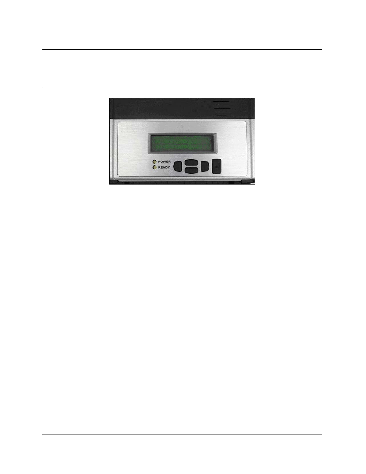
NOTE: (7008 printers only) the LCD briefly displays PRESS RIGHT ARROW FOR
MENU. Then the LCD displays “Tally Dascom 7008” for about one second. When
the printer is ready to print, the LCD displays “Tally Dascom” (see Figure 2-18
below).
Figure 2-18: LCD Display
5. Press the Power Switch to OFF and confirm the Power and Ready Light turn off
before proceeding to the next steps. Refer to Figure 2-12 in step 1 of the Power Test
section of this manual, to locate the power button on the printer.
Page 32
Getting Started
2-22
Thermal Transfer Ribbon Loading (TT Printers Only)
To run the printer in thermal transfer mode, a ribbon must be loaded properly into the
printer in order to print. This section details step-by-step instructions on how to load
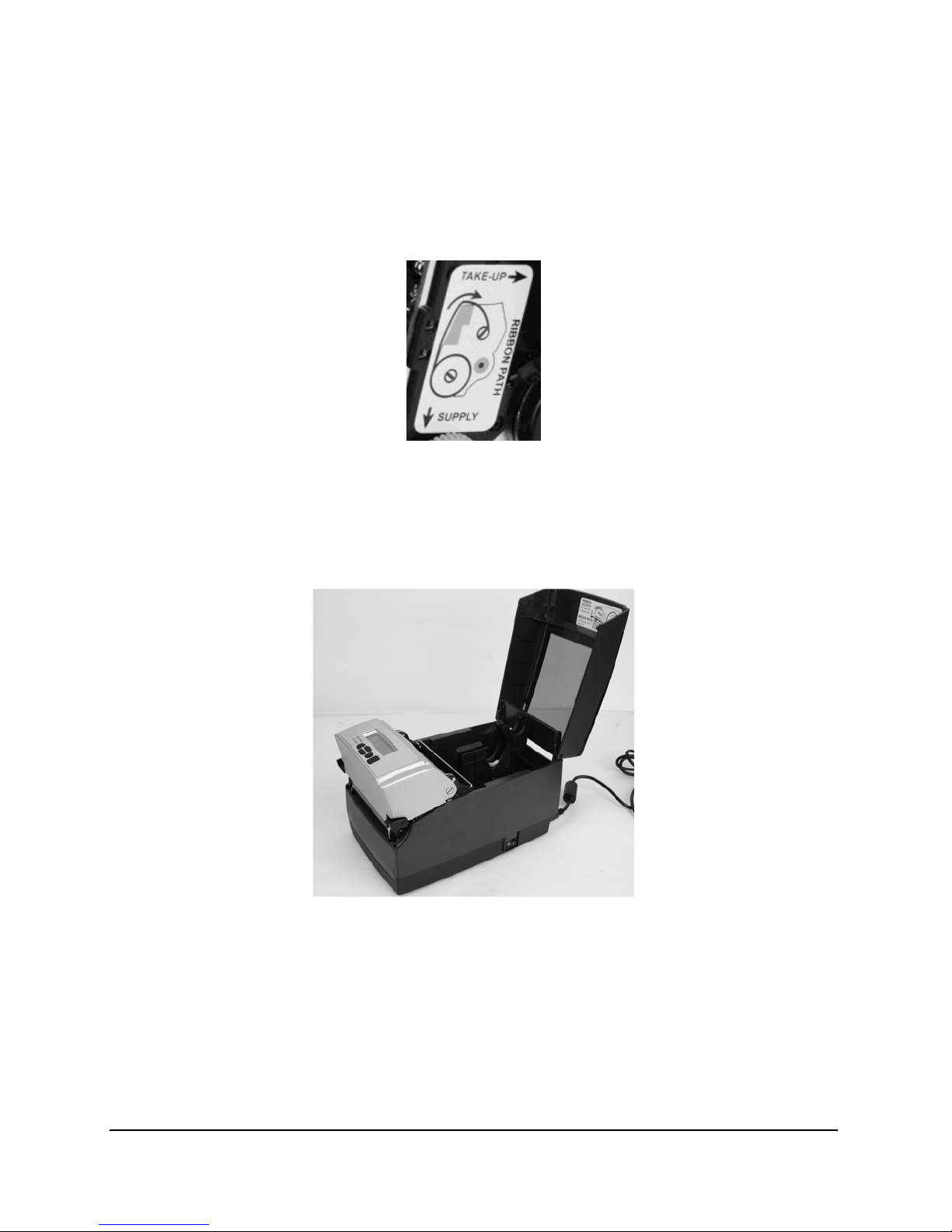
thermal transfer ribbon into the printer. There is a ribbon loading label on the side of the
printhead mechanism for all thermal transfer printers as shown in Figure 2-19 below.
Figure 2-19: Ribbon Loading Label
For ribbon specifications and details please refer to the Consumables Guide on the Installation CD or the manufacturers web site.
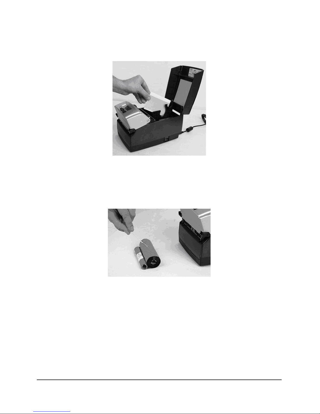
1. Lift the top hinged dust cover.
Figure 2-20: Lifting the Dust Cover
Page 33
Getting Started
2-23
2. Remove the Test Sample from inside the printer, and store it with other documenta-
tion for future reference.
Figure 2-21: Removing the Test Sample from the Printer
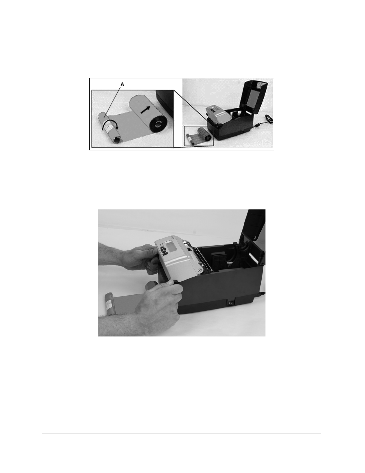
3. Place the sample ribbon provided with the printer, in front of the printer for loading.
Place the large media end towards the printer with the small take up roll end facing
away from the printer as shown in Figure 2-22 below. Gently remove the tape off the
ribbon to prepare for ribbon loading.
Figure 2-22: Removing Tape Off of the Ribbon
Page 34
Getting Started
2-24
4. Once the tape is removed, discard the tape, and spread the ribbon out so the text on
the leader A is facing down. Make sure the ribbon does not roll off the table when
setting it down.
Figure 2-23: Ribbon Layout Before Loading Into the Printer
5. Next, unlatch the printhead mechanism to load the ribbon into the printer. To do
this, pull up on the black latches with both hands. Refer to the figure below to
release the printhead mechanism.
Figure 2-24: Unlatching the Printhead Mechanism
Page 35
Getting Started
2-25
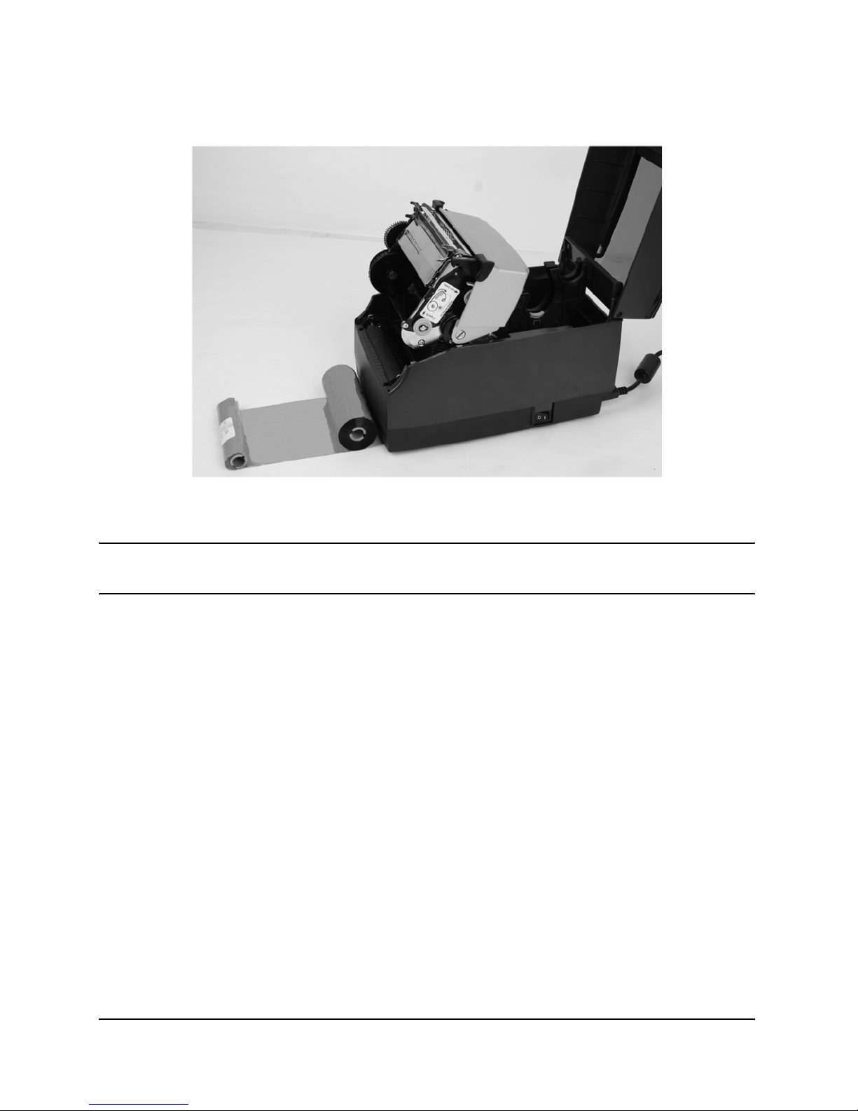
6. Next, raise the printhead mechanism fully. Refer to the figure below.
Figure 2-25: Fully Raised Printhead Mechanism
CLEANING NOTE: This is the ideal position for cleaning the printhead, printhead
shield, and platen.
Page 36
Getting Started
2-26
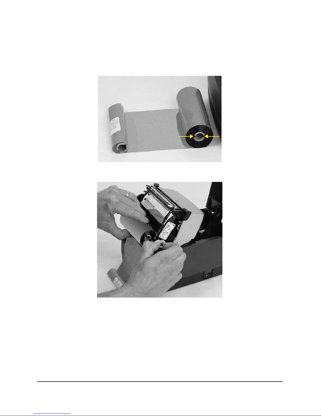
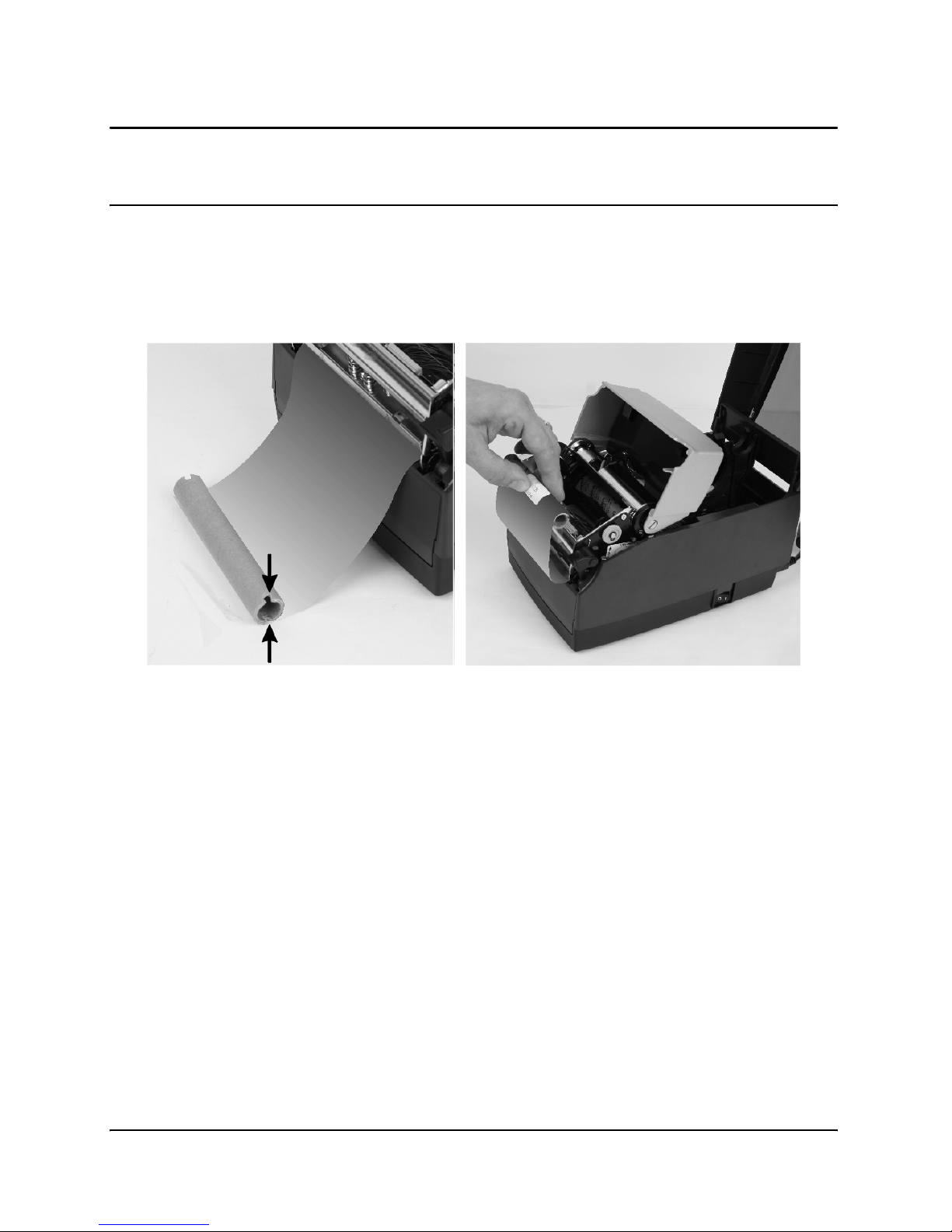
7. Next, insert the ribbon supply roll. Lift the ribbon supply roll, as shown in
Figure 2-26, with one hand as it currently is positioned with the leader text showing.
Examine the ends of the ribbon supply roll and notice the notches on the roll. These
notches fit into the printer. Refer to Figure 2-27 for clear pictures of the notches.
Figure 2-26: Ribbon Supply Core Notches
Figure 2-27: Lining up the Ribbon Supply Core Notches with the Supply Spindle Notches
Page 37
Getting Started
2-27
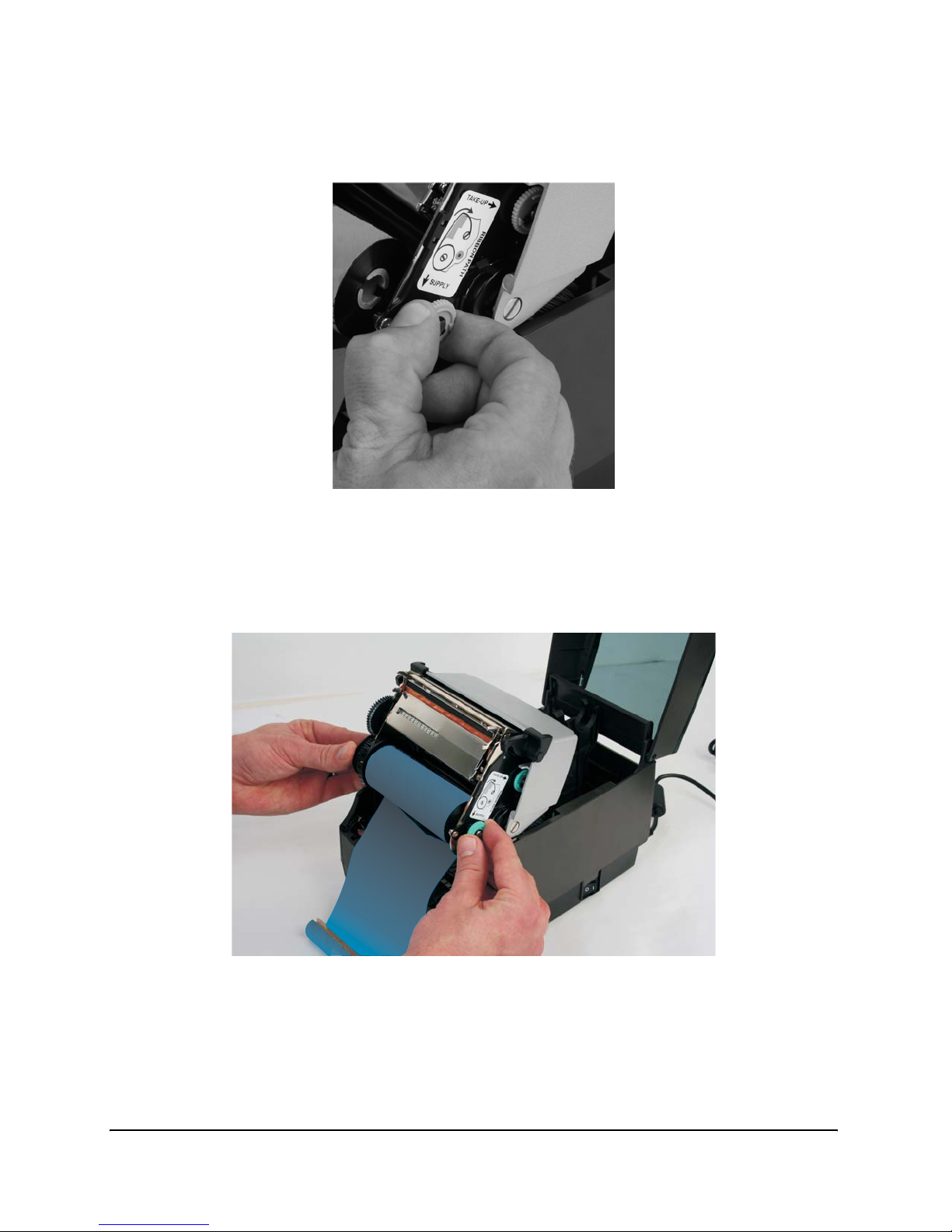
8. While holding the ribbon in place, pull gently on the green supply spindle to insert
the ribbon supply roll into place.
Figure 2-28: Pulling Out the Ribbon Supply Spindle
9. Place the ribbon supply roll into position as shown in Figure 2-29 below. Line up the
notches on the ribbon supply roll with the printer supply spindle tabs to secure the
ribbon supply roll into place.
Figure 2-29: Lining up the Supply Roll Core with the Ribbon Spindle tabs
Page 38
Getting Started
2-28
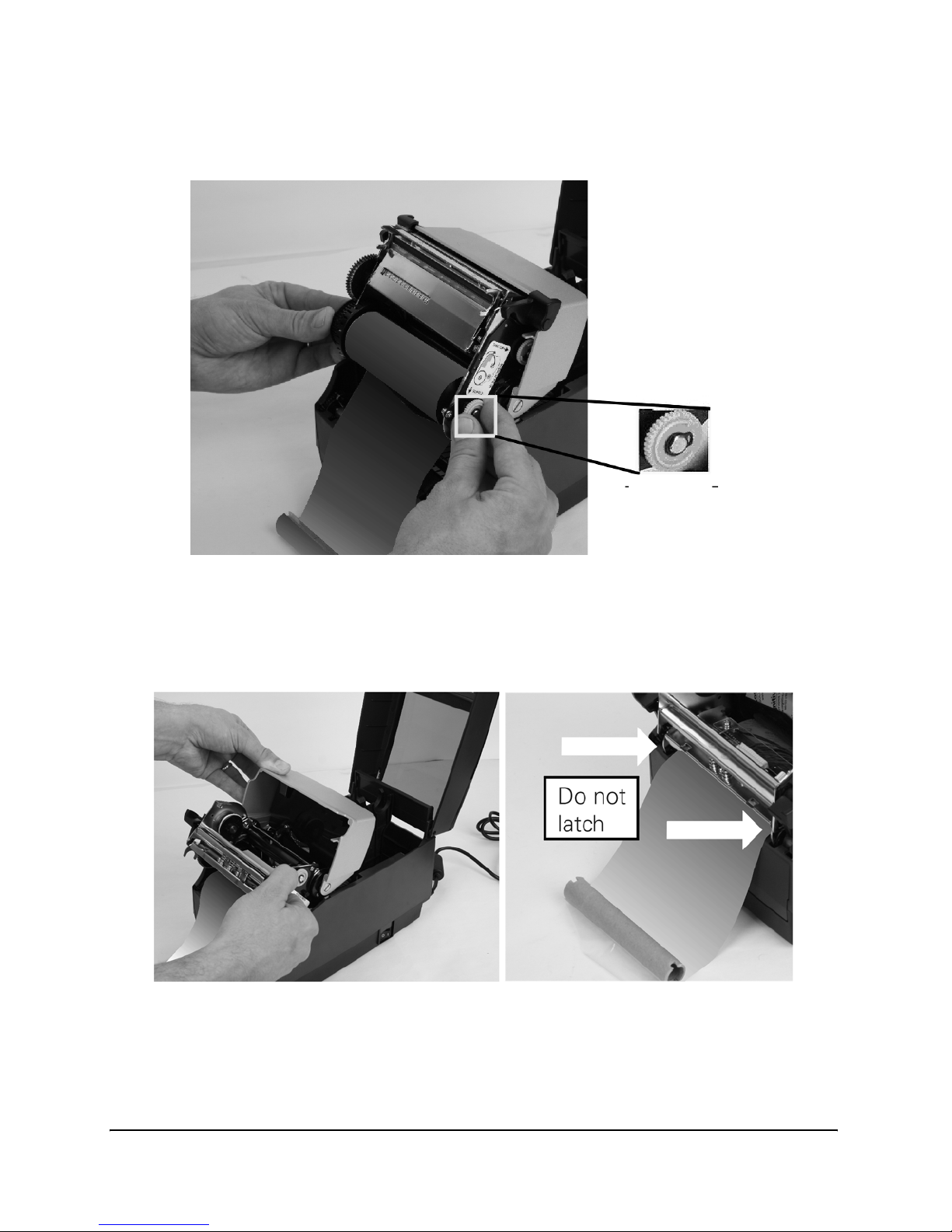
10. When the ribbon feels secure, gently push and rotate the green supply spindle clock-
wise, while holding the supply clutch hug, until the ribbon seats properly.
Figure 2-30: Supply spindle Rotation to Secure Supply Roll In Place
11. Once the ribbon supply roll is loaded, gently lower the printhead mechanism down
with one hand while holding the user interface cover with the other hand. DO NOT
LATCH the printhead mechanism. Refer to Figure 2-31.
Figure 2-31: Separating and Lowering the Printhead Mechanism from the User Interface
Without Latching the Mechanism
Page 39
Getting Started
2-29
NOTE: If the printhead mechanism latches, a clicking noise will sound. If the
printhead mechanism is latched by mistake, push up the black printhead
latches to release the printhead mechanism as shown in Figure 2-24.
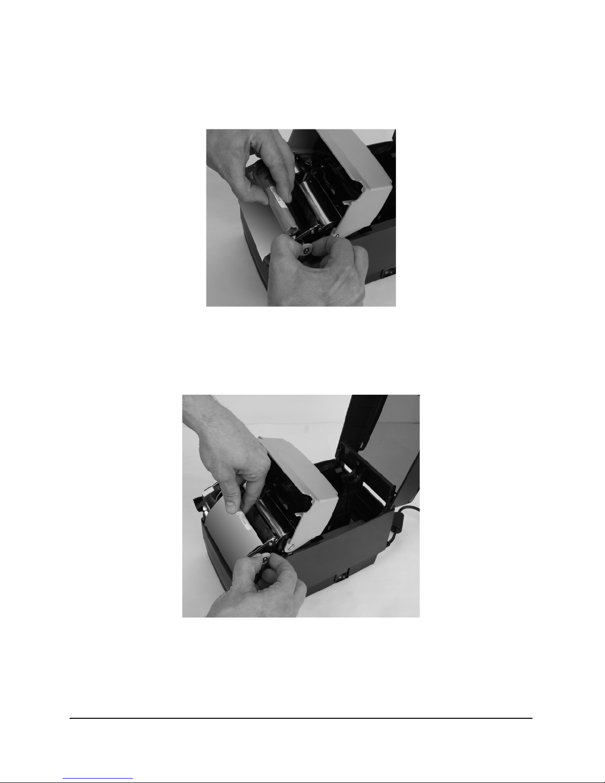
12. Next, install the ribbon take up roll. Examine the ends of the ribbon take up core
and notice the notches on the ribbon core. These notches fit into the printer. Refer to
Figure 2-32 for clear pictures of the notches. Lift the ribbon take up roll as shown in
the figures below.
Figure 2-32: Take up Roll Notches and Loading the Take Up Roll
Page 40
Getting Started
2-30
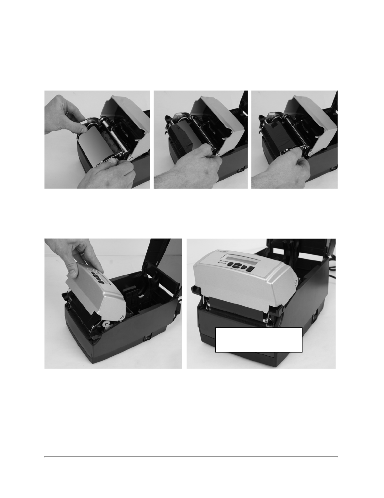
13. Pull gently on the green take up spindle to insert the ribbon take up roll into place.
Line up the notches on the ribbon take up core with the printer take up spindle
notches to secure the take up roll into place.
Figure 2-33: Pulling the Take Up Spindle Out to Insert Take Up Roll
14. Place the ribbon take up roll into position as shown in Figure 2-34. Once the ribbon
feels secure, gently push and rotate the green take up spindle clockwise to make
sure the ribbon take up core is engaged with the notches on the printer.
Figure 2-34: Seating the Ribbon Take Up Core Into the Take Up Spindle Notches
Page 41
Getting Started
2-31
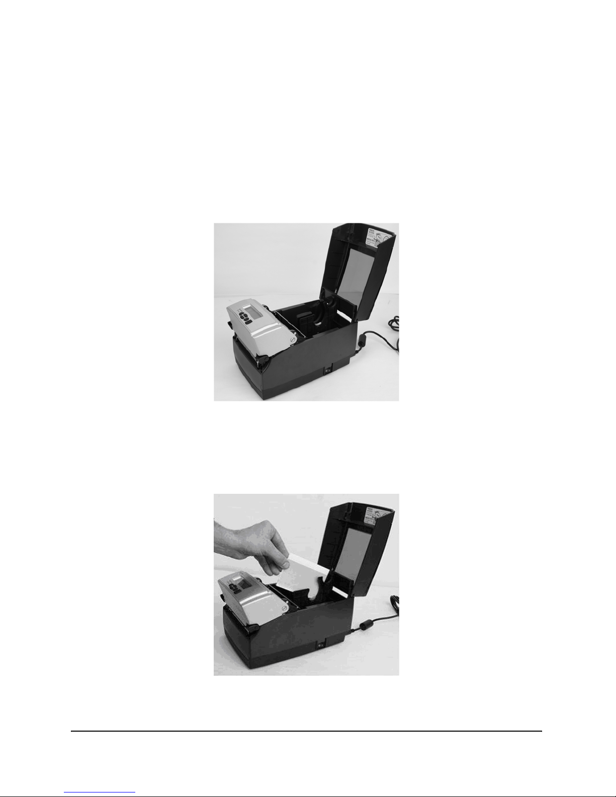
15. Once the ribbon take up core has been installed, turn the take up spindle clockwise
to wind the ribbon leader onto the take up core. Rotate the green take up spindle
clockwise until the black ribbon begins winding on the take up core as shown in
Figure 2-35.
Figure 2-35: Winding the Ribbon Onto the Take Up Core
16. Gently lower the user interface but DO NOT LATCH the printer. Refer to
Figure 2-36.
Figure 2-36: Lowering the User Interface without Latching the Mechanism
Set User Interface Down:
DO NOT LATCH
Page 42
Getting Started
2-32
Loading Media
All printers have media loading instruction labels on the bottom of the dust cover.
To increase the life of the printhead, we recommend using media approved by the manufacturer with all printer models. The printhead warranty requires approved media. For
more information regarding approved media please contact a local reseller or the manufacturer
1. Lift the top dust cover (Thermal Transfer printers have already completed this step
in the ribbon loading section).
Figure 2-37: Lifting the Dust Cover
2. Remove the Manufacturing Test Sample from inside the printer and file the Manu-
facturing Test Sample with the other documentation for future reference (Thermal
Transfer printers have already completed this step in the ribbon loading section).
Figure 2-38: Removing the Manufacturing Test Sample from the Printer
Page 43
Getting Started
2-33
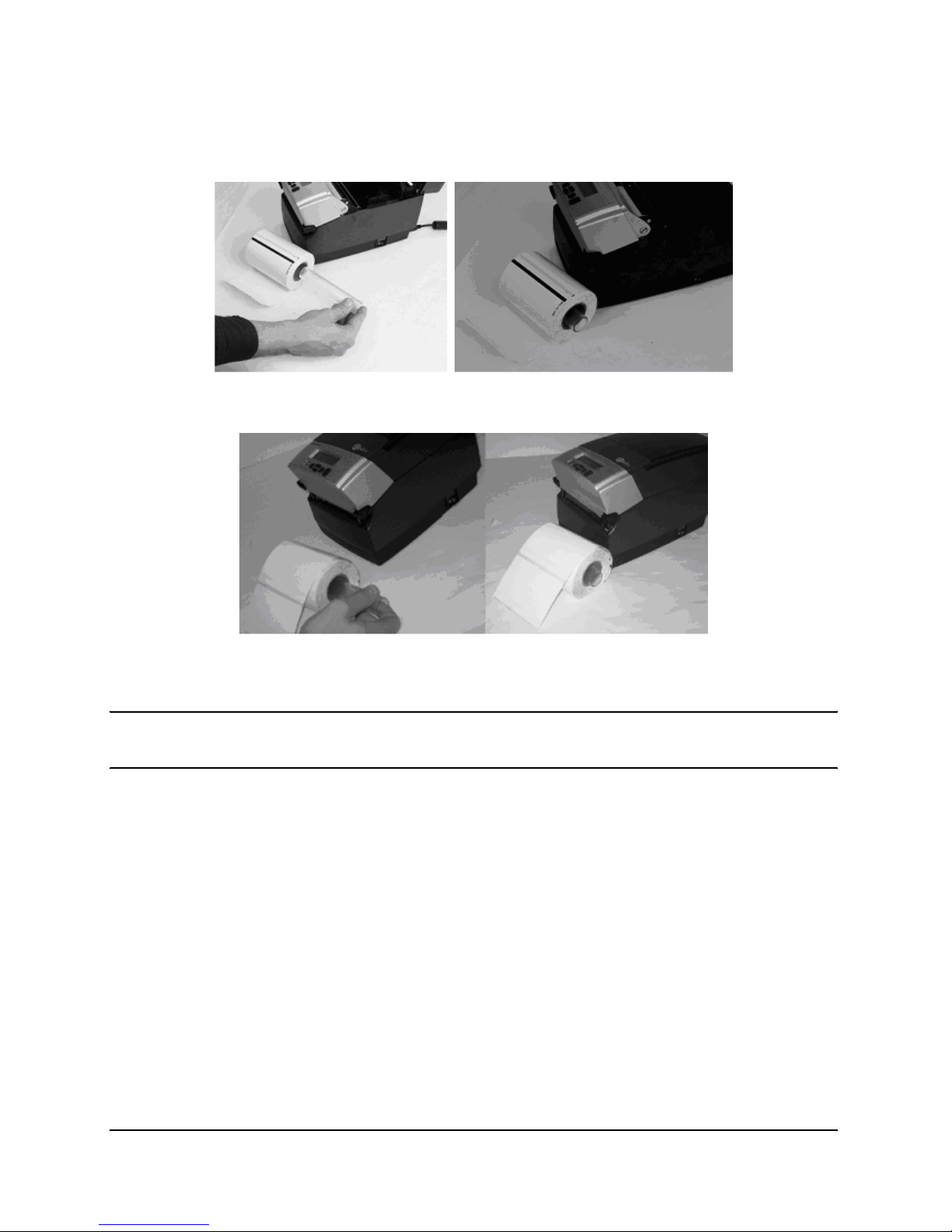
3. Insert the spindle into the approved sample media roll (see inward and outward
wound media figures below).
Figure 2-39: Inserting the Spindle Into the Approved Inward Wound Media
Figure 2-40: Inserting the Spindle into Outward Wound Media
NOTE: For more information regarding approved media please contact a local
reseller or the manufacturer.
Page 44
Getting Started
2-34
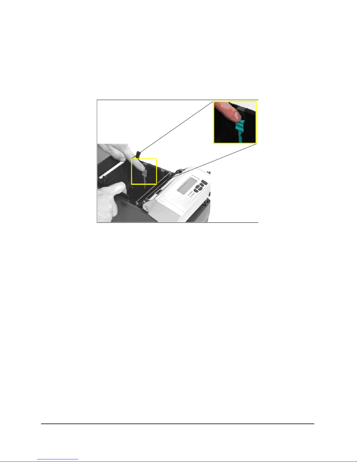
4. Prior to loading media, take a moment to review operation of the media guides. The
guides are spring loaded in order to provide proper media control during printing.
The right media guide has a green locking tab as shown in Figure 2-41, that holds
the guides in any position. This is useful if the same width media is often used. Once
the guide is set to the width of the media, it can be locked in place and future loading
of media is simplified.
Figure 2-41: Media Guide Locking Tab
Page 45
Getting Started
2-35
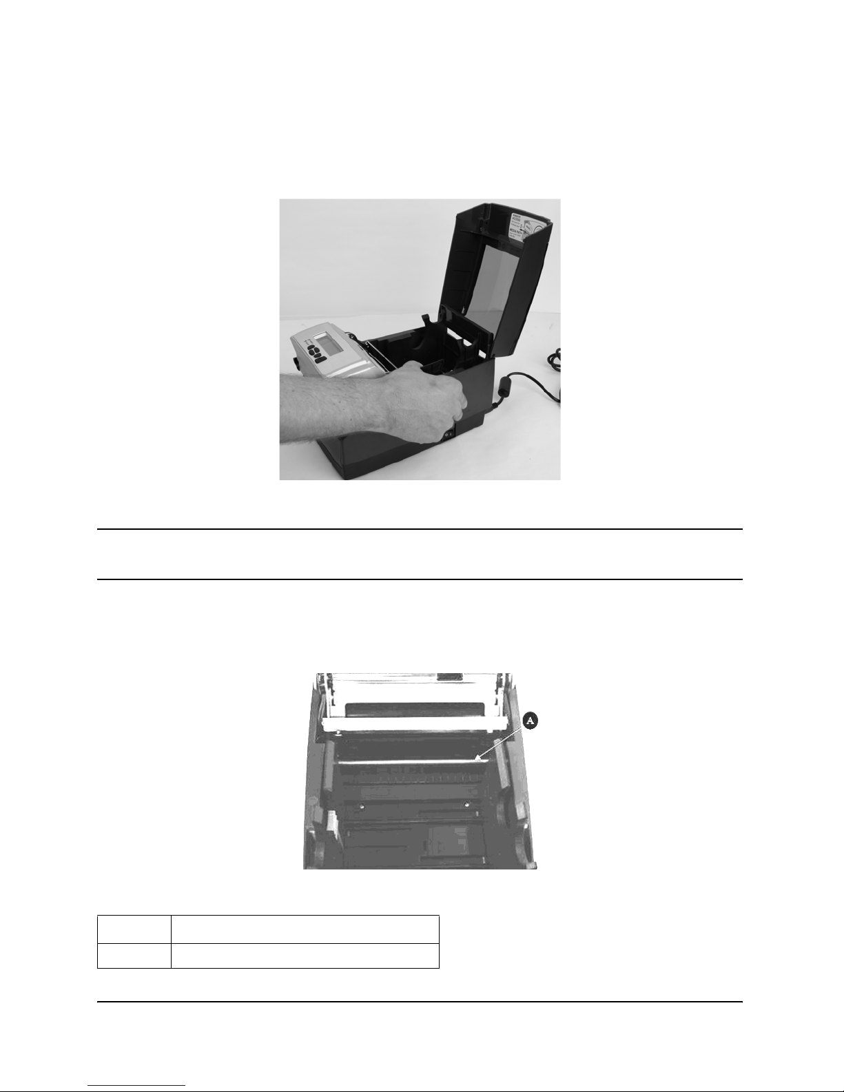
5. To initially set the media guides to the proper setting, try to push either guide to the
outside of the printer. If the guide does not move, lift up slightly on the green lock
until it stops in the upright position. Move the media guide to the outside of the
printer as shown in Figure 2-42.
Figure 2-42: Spread the media guides apart
NOTE: The lock can be removed if it is pulled up too hard. If this happens, reinsert the lock in the media guide.
6. Locate the media guide bar in the rear of the mechanism, indicated by the arrow in
Figure 2-43 below. The media must be placed under the media guide bar, or media
wandering can occur.
Figure 2-43: Top View of Media Guide from Behind Printer
Device Use
A Guides the labels through the printer
Page 46
Getting Started
2-36
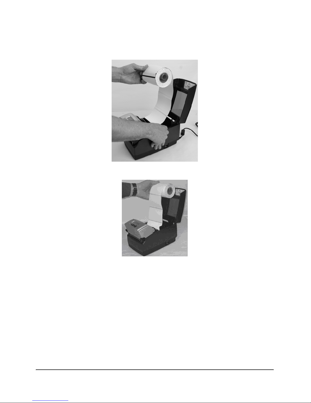
7. Unroll a few labels. Position the media, print side up, into the printer as shown in
Figure 2-44 and 2-45.
Figure 2-44: Media Print Side Must be Facing Up for Inward Wound Media
Figure 2-45: Media Print Side Must be Facing Up for Outward Wound Media
Page 47
Getting Started
2-37
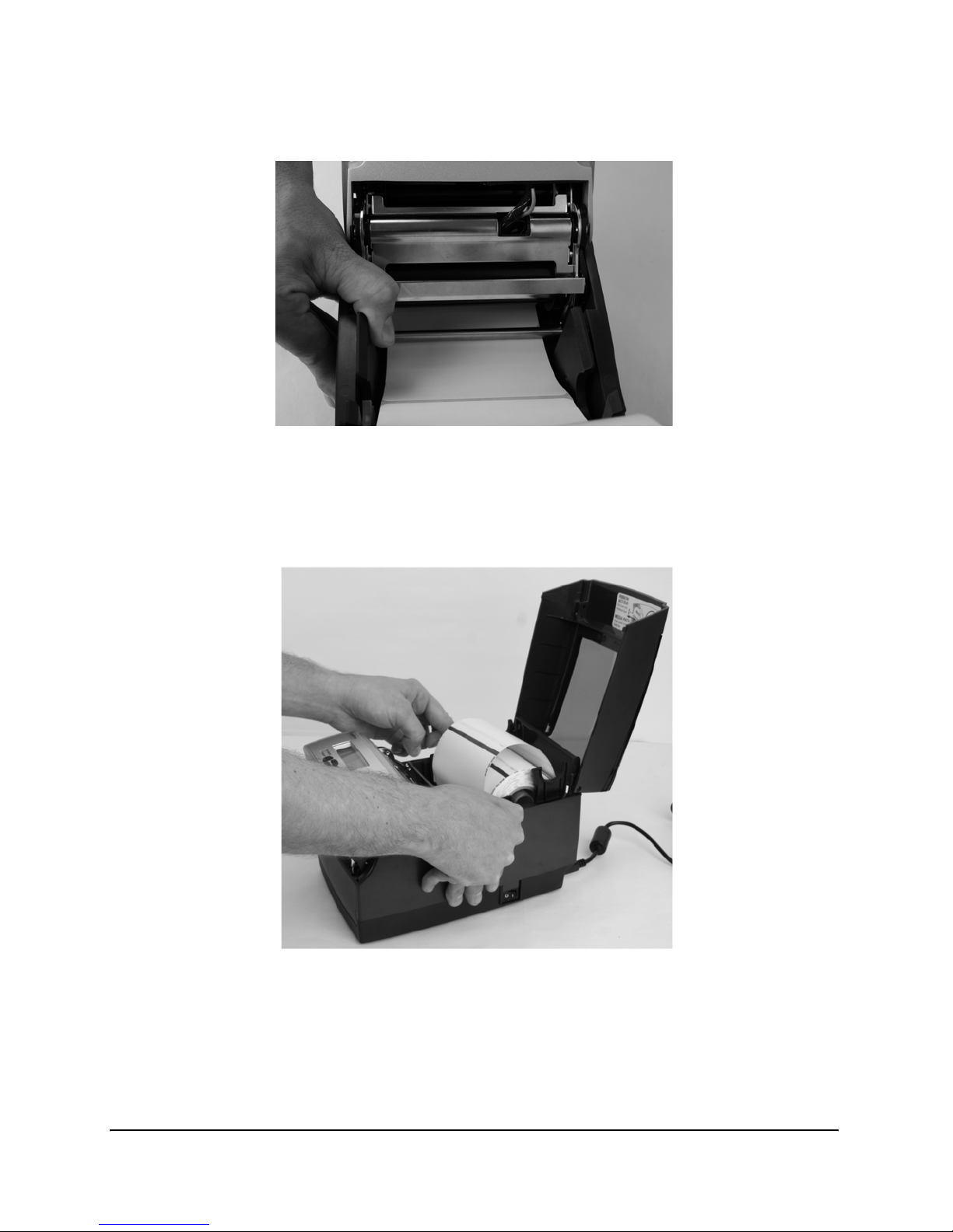
8. Place the media under the media guide bar as shown in Figure 2-46.
Figure 2-46: Place the Media Under the Media Guide Bar
9. Lower the media between the two media guides. Position the media as shown in Fig-
ure 2-47. Before completely lowering the spindle in the slots as shown, unlock the
guides if they are locked, so they can spring load against the sides of the media roll.
Figure 2-47: Lower the Media Roll Into Lower Media Guide Slots
Page 48
Getting Started
2-38
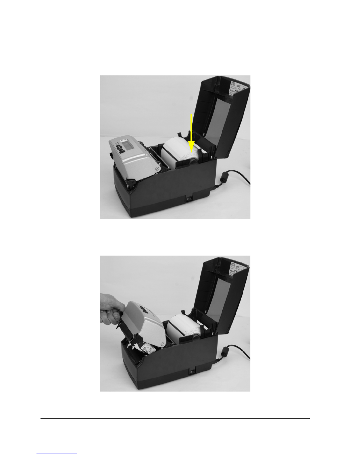
10. Once the guides are against the sides of the roll, push the roll down in the slot as
shown in Figure 2-48. This locks the media guide in the proper position. The media
should look as shown.
Figure 2-48: Push Down on the Right Side of the Roll to Lock the Media Guide
11. Lift the mechanism as shown in Figure 2-49.
Figure 2-49: Lift the Mechanism
Page 49
Getting Started
2-39
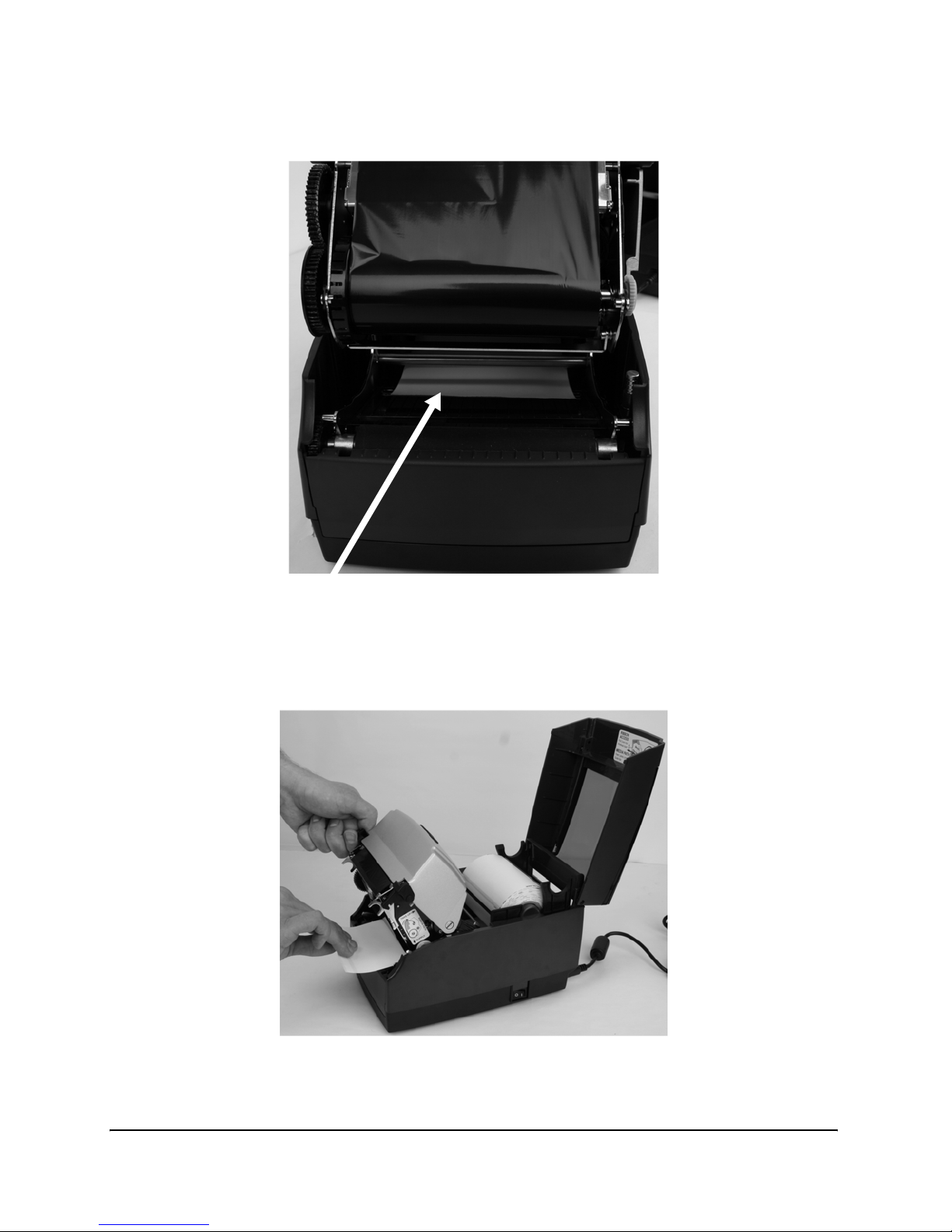
12. The media should be visible as shown in Figure 2-50 below the round metal rod.
Figure 2-50: Front View of Media Being Loaded Under Media Guide
13. Pull the media forward three to four inches from within the mechanism, past the
drive platen, as shown in Figure 2-51. Center the media on the platen before proceeding to the next step.
Figure 2-51: Pulling the Media Three to Four Inches then Centering on the Platen
Page 50
Getting Started
2-40
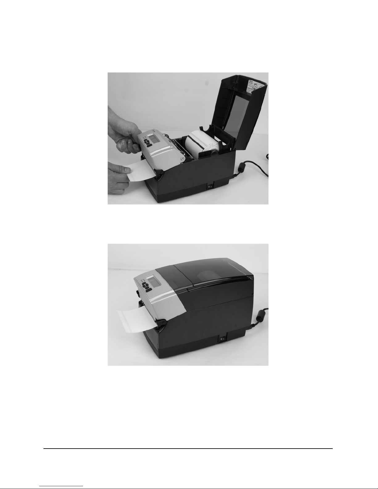
14. Once the media is pulled forward three to four inches, latch the mechanism as
shown in Figure 2-52.
Figure 2-52: Latching the Mechanism
15. Close the dust cover to enclose standard size media while printing.
Figure 2-53: Closed Dust Cover
Page 51
Getting Started
2-41
Loading Large Roll OD Media
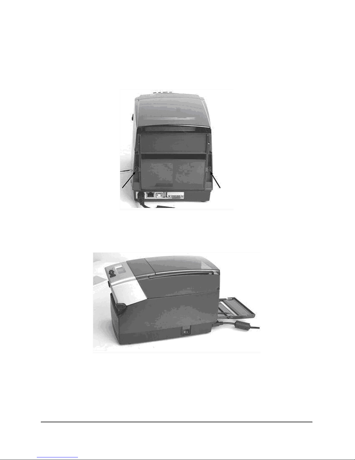
1. Locate the rear door screws at the rear of the printer as identified with the arrows in
Figure 2-54. Remove the screws with a #2 Phillips screwdriver. Keep the screws for
future usage.
Figure 2-54: Rear Door Screws Identified by Arrows
2. Open the rear door and leave it in the position shown in Figure 2-55.
Figure 2-55: Open Rear Door as Shown
Page 52
Getting Started
2-42
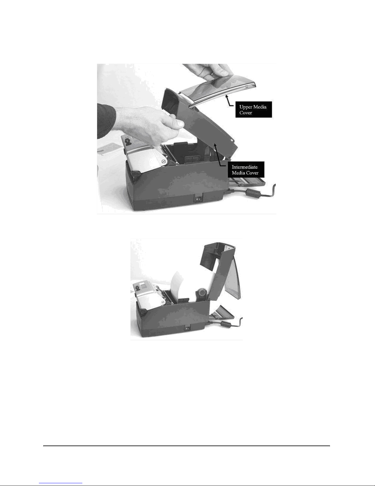
3. Open the media covers as shown in Figure 2-56.
Figure 2-56: Loading Large Media Roll, Print Side Up
Figure 2-57: Large Media Roll in Position
Page 53
Getting Started
2-43
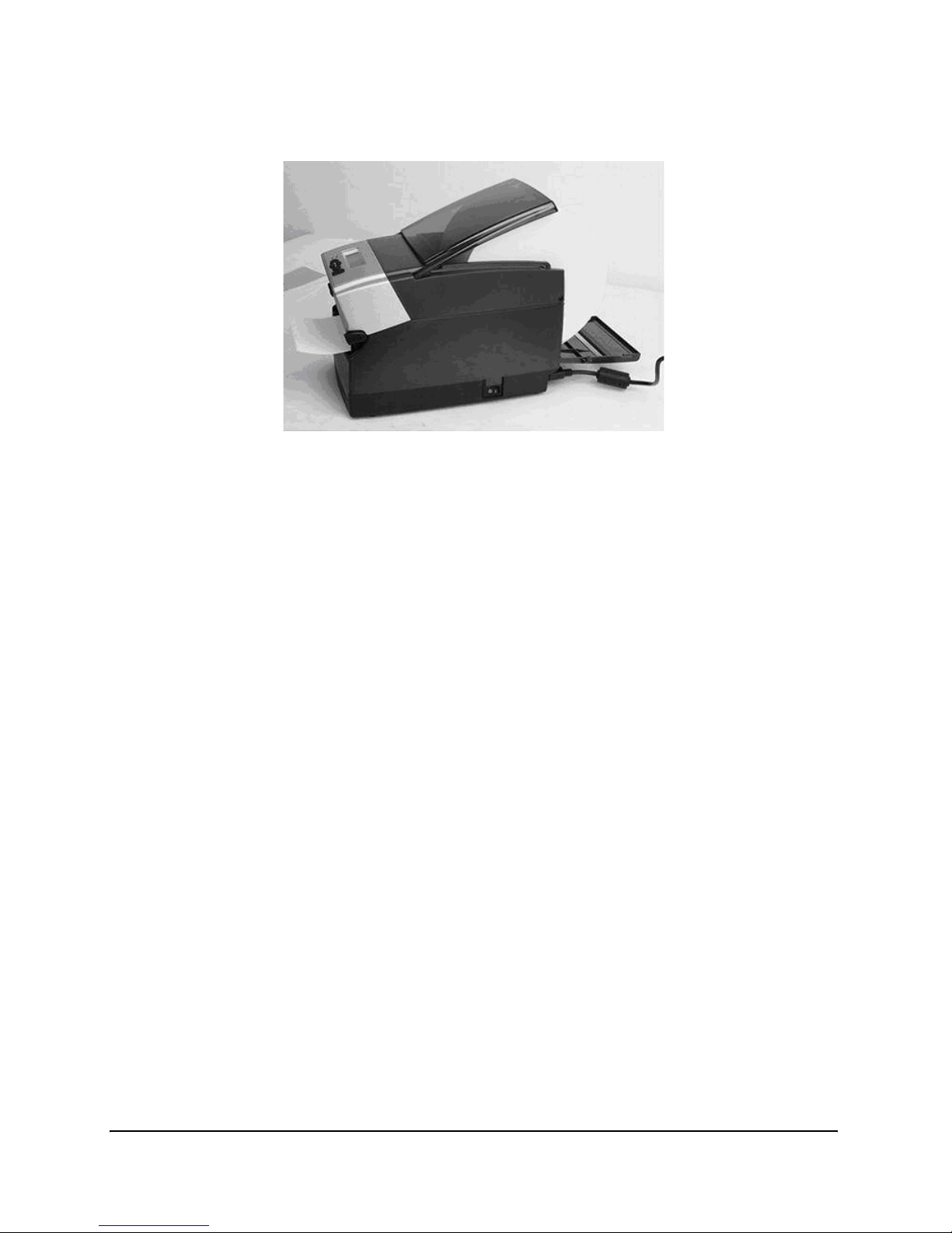
4. Close the top cover and let the dust cover rest on the large media roll.
Figure 2-58: Closing the Top Cover
Page 54
Getting Started
2-44
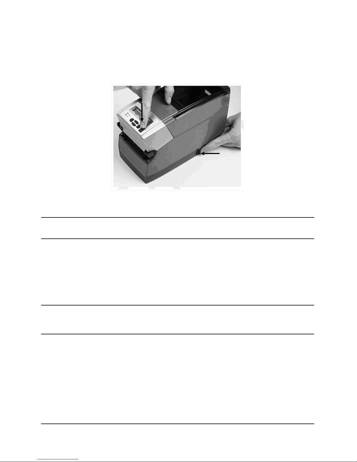
Performing the Self Test
The self test checks the printer’s overall operability, and lists the printer’s current settings. Refer to the figures and instructions below to perform the printer self test.
Figure 2-59: Performing the Printer Self Test
IMPORTANT! The printer should be loaded with media, connected to AC power,
and turned on.
1. Press and hold the FEED button.
2. Turn the printer ON while holding the FEED button.
3. Release the FEED button when the self test starts to print.
4. Turn the printer off and then on again to return to normal printing operation.
IMPORTANT! After performing the self test, the printer is in hexadecimal dump
mode and cannot print normally until the power is cycled (turned off, then
turned on again).
Page 55
Getting Started
2-45
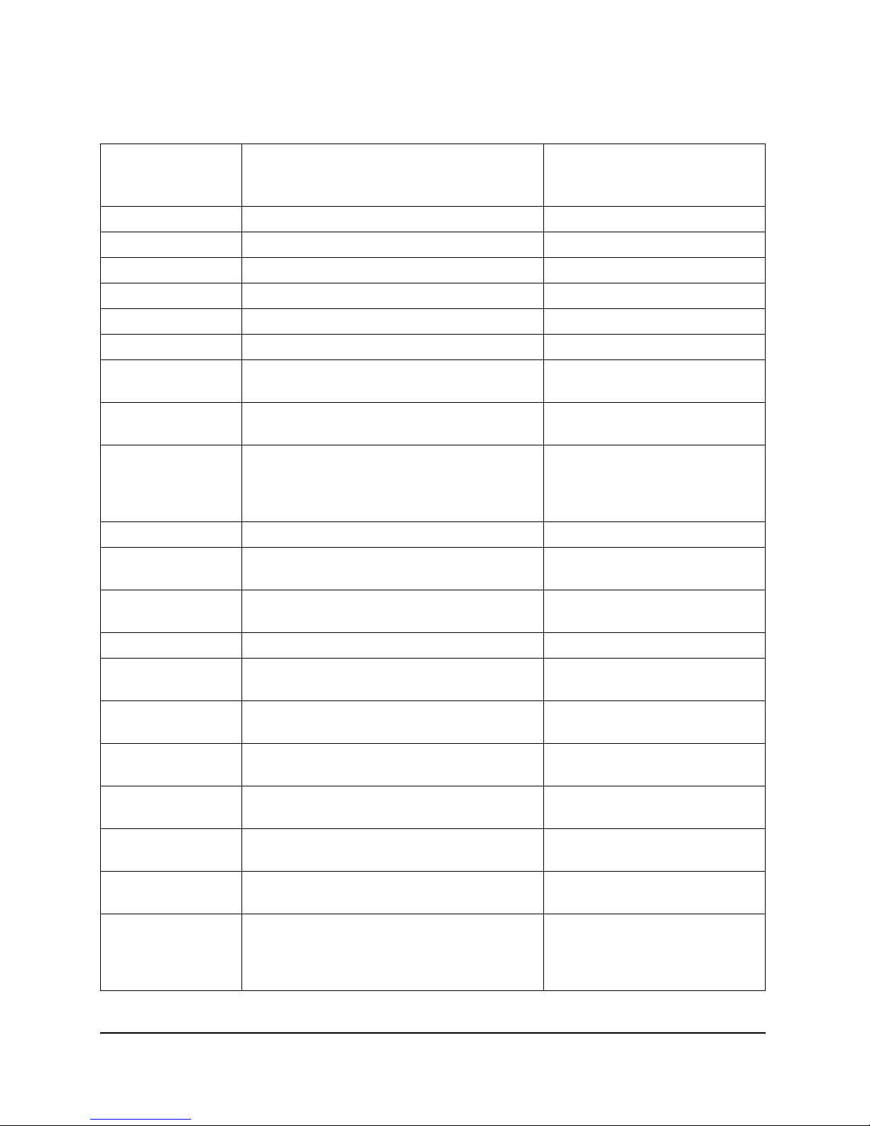
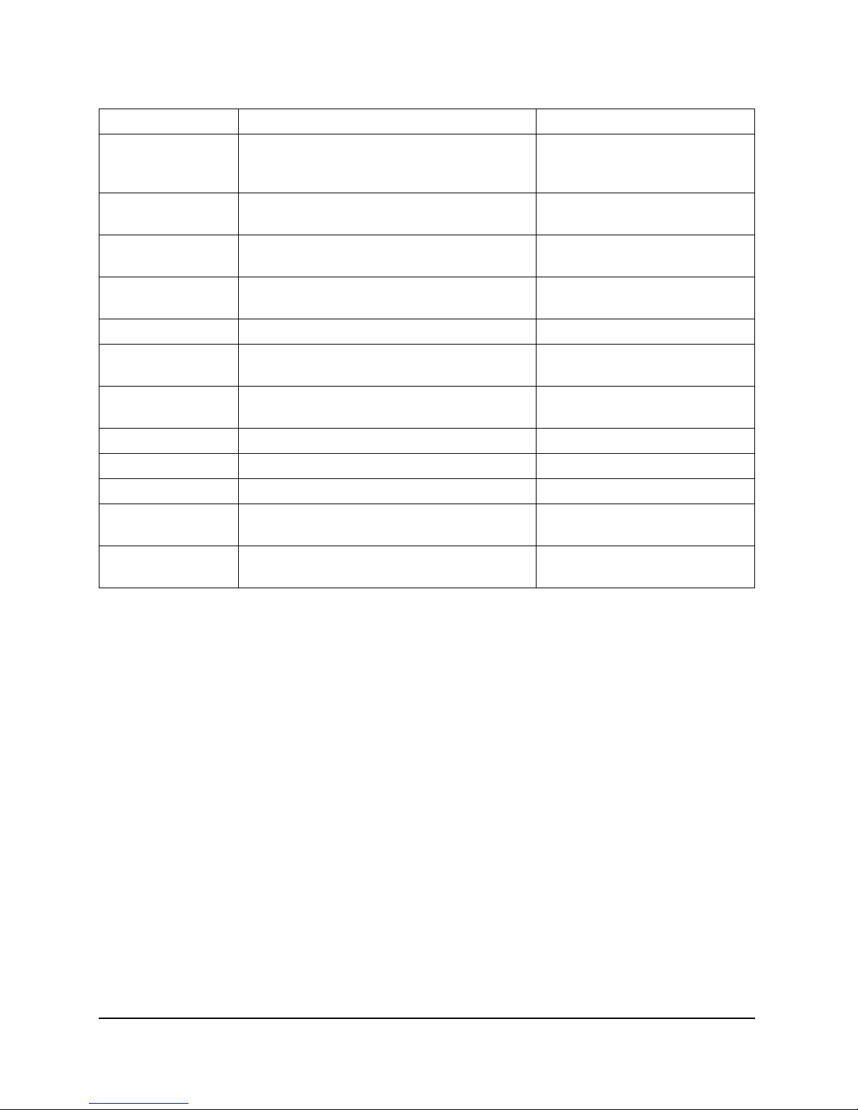
The output from the self test is described in the table below.
Setting Description
Example (Actual settings may
vary from examples listed
below)
FW Firmware version and date FW: 195-170-149 V1.49
S/N Printer serial number S/N: P012345678
RAM, FLASH RAM and FLASH size RAM=18MB, FLASH=8MB
Inches Printed Total inches printed Inches Printed: xxxx
Printer Settings
Aux. Power Enable 5 VDC output through Serial port. Aux. Power: OFF
Buffer Reset
(1/10sec)
Enables or disables the buffer reset timer. Buffer Reset (1/10sec): 65535
Comm Communications port configuration values
(Baud, Parity, Data Bits, Stop Bits)
Comm: 9600,N,8,1,OFF
Darkness Darkness setting of printer. First number is
factory setting (not user modifiable). Second
number is the variable, user modifiable setting.
Darkness: 0 (0)
Energy Offset Adjusts the Energy Density. Energy Offset: 0 (0)
Feed Speed Speed at which media is fed using the FEED
button.
Feed Speed : NORMAL
Index Enabled Current state of Indexing. Either enabled or
disabled (No Index).
Index Enabled
Feed Type Current Indexing mode. GAP, BAR or Notch. Feed Type: GAP
DTBAR Index sensor settings for Black Bar indexing
in Direct Thermal print mode.
DTBAR: R=56 T=13 G=0
TTBAR Index sensor settings for Black Bar indexing
in Thermal Transfer print mode.
TTBAR: R=50 T=15 G=0
DTGAP Index sensor settings for Gap indexing in
Direct Thermal print mode.
DTGAP: R=1 T=16 G=0
TTGAP Index sensor settings for Gap indexing in
Thermal Transfer print mode.
TTGAP: R=1 T=40 G=0
DTNOTCH Index sensor settings for Notch indexing in
Direct Thermal print mode.
DTNOTCH: R=20 T=5 G=0
TTNOTCH Index sensor settings for Notch indexing in
Thermal Transfer print mode.
TTNOTCH: R=50 T=1 G=0
No Media (inches) Distance (in inches) the label travels before
the printer either attempts to recalibrate, or
errors out with a red ready light. (Gap indexing mode only)
No Media (inches): 1
Page 56
Getting Started
2-46
Pitch (dots) Print density in dots per inch Pitch (dots): 200
Present Label When ON, Printer will advance and reverse
the distance specified below for each label
printed.
Present Label: ON
Advance With PRESENTLABEL ON, the distance that
a label is advanced, in hundredths of an inch
Advance: 15
Reverse With PRESENTLABEL ON, the distance that
a label is retracted, in hundredths of an inch
Reverse: 15
Print Mode DT indicates direct thermal printing, TT indi-
cates thermal transfer printing
Print Mode: DT (TT)
Print Speed Displays the current printing speed setting. Print Speed: HIGHSPEED
Report Level Sets the manner in which the printer reports
recoverable errors.
Report Level: 2
Shift left: (1/100)
inches)
Distance the image is shifted to the left, in
hundredths of an inch
Shift left: (1/100) inches): 0
Text Buffer:
Size Size of the text buffer Size: 65535
Overflow Overflow value for the text buffer Overflow: 1024
User Feedback Shows the status of VARIABLE
USER_FEEDBACK
User Feedback: OFF
Width Default label width (approximate), in hun-
dredths of an inch
Width: 425 (864 dots)
Page 57

3-1
Chapter
3
Software Installation
For all models there are two methods to install the required software.
METHOD A: Install Software Using the Installation CD
Place the Installation CD into the computer and the CD automatically runs through all
the required steps to properly install the required software for the printer. When the
installation is complete, proceed to Chapter 4 of this User’s Guide.
METHOD B: Install Software Using the Web Site
Our web site (http://jadmin.dascom.com) will be permanently updated with the newest
version of software and documentation. You are able to find the following data:
` Printer driver.
Install the printer driver software.
` Administrator Tool.
Install the Administrator configuration software.
` Java
TM
Runtime Environment (automatically installed).
Page 58

Software Installation
3-2
Windows Driver Installation
NOTE: Please ensure to install the drivers BEFORE connecting the printers to
the PC.
1.
Browse to the drivers directory: [Drive]:\Users\<logon_name>\TallyDascom\Drivers
2. Run the PrnInst.exe.
3. Select the printer model you want to install (see the rating plate for details)
4. Proceed with Next.
5. Select and/or create the port you intend to connect the printer.
6. Finish the installation process.
7. Now, connect the printer.
8. Switch on the printer.
9. The printer will be available in your windows system.
Setting Printing Preferences
The printer driver must be configured for the user’s specific needs. Use the following
steps to set the default printer driver preferences.
1.
Click Start.
2. Click Settings and choose Printers and Faxes.
3. Right-click on the printer icon and choose Properties from the shortcut menu. The
Properties dialog box appears.
4. Click Printing Preferences. The Printing Preferences dialog box appears.
5. Click each tab and set the options to match the user’s specific printing requirements.
6. Click OK to close the Printing Preferences dialog box.
7. Click OK to save the printing preference and close the Properties dialog box.
Page 59

Software Installation
3-3
Installing and Running the Administrator Software
The Administrator configuration software allows the user to configure, test, and operate
the printer.
Installing the Administrator Configuration Software
1. Navigate to the temporary folder the file was copied.
2. Double-click the CAdminInstall.exe file. The InstallShield Wizard starts.
3. Please follow the instruction on the screen.
Page 60

Page 61
4-1
Chapter
4
Using the Administrator Tool
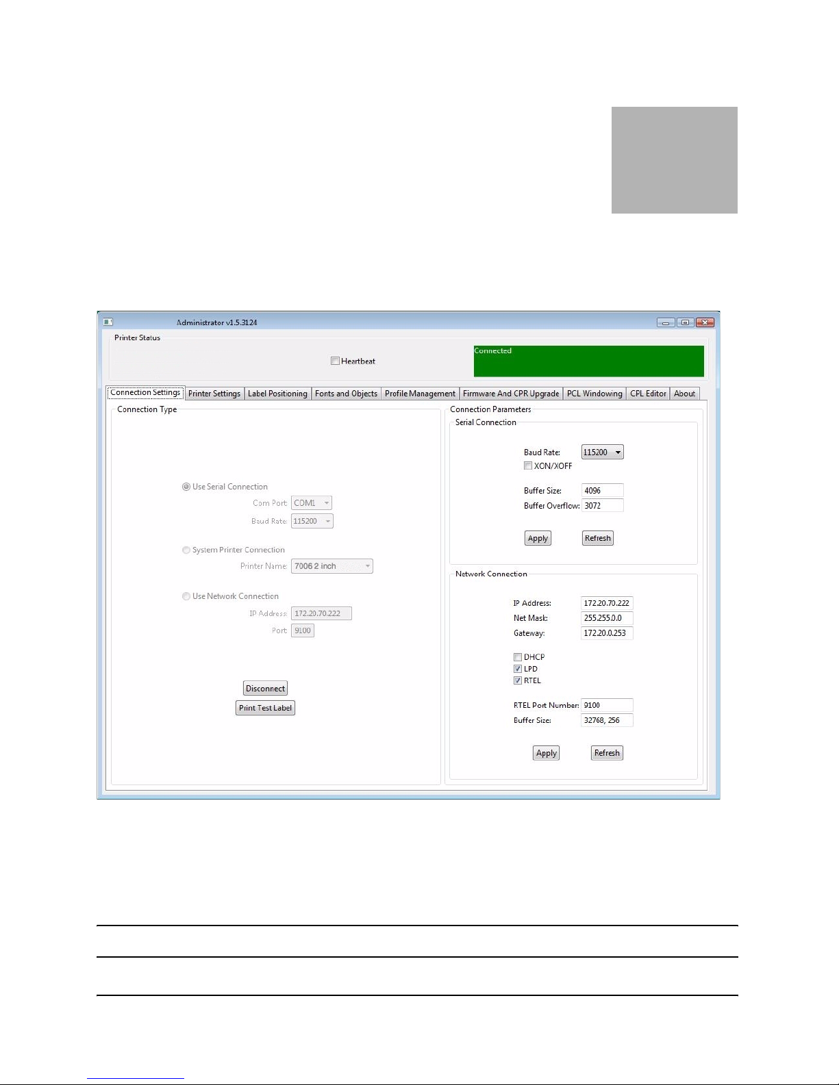
Select the connection method being used between computer and printer.
` If using serial, select the appropriate communication port and baud rate. The default
serial baud rate is 9600.
` If using USB, select the appropriate printer driver.
NOTE: Refer to Chapter 3, “Windows Driver Installation” for more details.
Page 62

Using the Administrator Tool
4-2
` If using Parallel, select the appropriate LPT port
` If using Network, select the correct IP address.
NOTE: Refer to Chapter 6 “Network Printing” and Chapter 2, “Connecting Data
Cables to the Printer” for more details.
Once connected, the software will display the connection method in green with a “Connected” message as shown below. On the right side of the window, the printer’s settings
will be displayed.
Next, print a self test label by selecting the “Print Self-Test Label” button located in the
lower right of the window. This will verify connection to the printer.
To change the printer’s setting, select the section to change and either manually enter the
new value, or select the new value from a list.
Select the apply button to send the new setting to the printer.
Selecting the “Refresh” button will refresh the printers current settings to verify the new
change.
Administrator Sections
The Administrator is divided into tabs. Each tab represents different abilities that the
software provides. Below is a brief description.
I/O Settings
Controls Host PC to Printer communication options, Printer Serial and Network options,
and Self-Test label printing.
Printer Settings
Printer settings control thermal printing method, darkness, print speed, pitch, indexing,
and real time clock settings.
For more details on printer settings please reference the Programmer’s Guide.
Calibrating the Printer
Calibrate the printer when the following occurs:
` Print media type changes
` Printer skips labels
` Printer feeds blank labels
We recommend using Method 1 listed below to calibrate the printer, however, users may
calibrate using any of the three listed methods below.
Page 63

Using the Administrator Tool
4-3
Method 1: Calibrate using the Administrator configuration software
Once properly installed as shown in Chapter 3 “Installing and Running the Administrator Software”, calibration may be performed using the Index Setting field in the Printer
Settings tab of Administrator.
To calibrate the printer, select the appropriate Index Setting (BAR, GAP or NOTCH),
then select “Apply”. This sets the correct indexing method.
To run a calibration, select the “Calibrate” button. The printer will respond with a ‘Successful’ or ‘Unsuccessful’ status message.
Method 2: Calibrate by Performing a Self Test
NOTE: See Chapter 2 “Performing the Self Test”.
When the Self Test has finished printing the printers default settings, the text ‘Press
Feed Switch Now to Calibrate Index’ will appear on the media. Press the Feed switch at
this time to perform the calibration.
Once completed, the Printer must be power cycled to return to its proper printing state.
If calibration was successful, pressing the Feed button will eject only one label at a time.
Method 3: Calibrate Using the Programming Language (CPL)
Calibration may also be performed using CPL commands via an available text editor.
Create a text file as shown below with the text editor:
! 0 0 0 0
VARIABLE INDEX SETTING CALIBRATE
VARIABLE WRITE
END
Send this file to the printer by selecting File-->Print. The printer will not print anything
but will move approximately one to two inches of media.
Advanced Printer Settings
Controls present label, print width, no media timeout, top of form, and various advanced
settings.
Select the field to modify and select the section’s apply button. Select “Refresh” to verify
the new settings were set.
Page 64

Using the Administrator Tool
4-4
Fonts/Objects
View the printer’s fonts, stored objects and graphics. Delete and loading objects is also
available with this setting.
The printer will display the list of installed fonts, stored objects, and graphics.
To delete an item, highlight the item and select “Delete Selected Object”.
WARNING! If an item is deleted, it is permanently removed from the printer.
To load an item, select “Load Object to Printer” and browse to the location of the file on
the host pc.
Profile Management
Profile Management provides the ability to download, save, open and apply printer profiles to printers. This is useful in updating multiple printers with the same settings.
To load the printer’s current profile, select “Get Current Printer’s Profile”. The printer
will display its settings.
To save the printer’s profile to a file, select “Save Profile to File” This creates a text file
with a .pfl extension. This profile can later be opened and sent to other printers connected
to the Administrator.
To open a previously saved file, select the “Open Stored Profile.”
To apply the displayed profile to a printer, select the “Apply Profile to Current Printer”.
Firmware Upgrade
Ability to view the current firmware version as well as upgrading firmware.
The current firmware version will display automatically.
To upgrade firmware, select “Select Firmware From Local Machine”.
Change files of type to “All Files” and browse to the directory with the firmware. Select
OK.
Select the Update Firmware button. This process can take 30 seconds to several minutes
depending on connection speed. Please allow the firmware to full update.
Page 65
Using the Administrator Tool
4-5
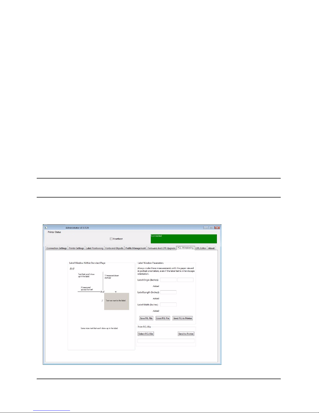
PCL Windowing
This tab is useful only for PCL-equipped printers (4 inch 300 dpi printers). It allows you
to make a label out of a full-page PCL document by specifying the small region of that
document you wish to print.
Since many PCL print images were designed to fit on 8-1/2”x11” or A4 paper, much of the
image won’t fit on a typical thermal printer label. Administrator provides a simple means
of cropping the desired image area to send to your printer. Here’s a quick example of how
to do this:
` In the “Label Window Parameters” area of the PCL Windowing page, simply enter the
upper left corner coordinates of the desired windowed area you wish to print from your
original image. View the page in portrait orientation when performing this operation.
` Enter the length and width of the label you’ll be using to print on with your printer. A
test print will appear to ensure your label size settings are correct. The box printed
should fit within the edges of your label.
` Test your PCL print file on the thermal printer by selecting the PCL file to be printed
using the “Select PCL File” button, located in the “Print PCL File” section.
NOTE: PCL is a true PCL HP5 compatible language. If the print file you’re using
is not compatible with PCL HP5, the print results may not be correct.
` If the desired print position isn’t correct, adjust the “Label Origin” values until the
desired print is located correctly.
Page 66

Using the Administrator Tool
4-6
CPL Editor
The CPL editor is a text editor/terminal program for communicating with the printer.
This editor allows the user to create, open or save text files, and send them to the printer.
To send a file to the printer, either type the information in the Printer Input side or select
“Open File” select the file and select “OK”.
To send the data to the printer, select “Send to Printer.” Any response that the printer
returns will be displayed in the Printer Indications section.
To save any printer response, select “Save Output”.
To clear the response, select “Clear Output”.
Page 67
5-1
Chapter
5
USB A Host
Loading Firmware Using a USB Flash Drive
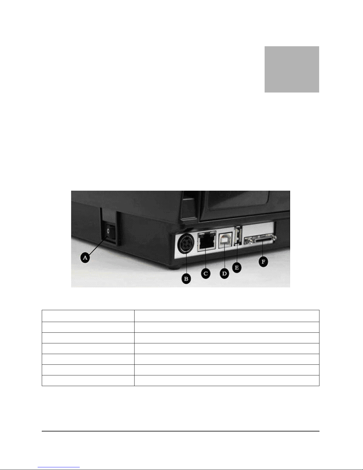
When a USB flash drive is inserted into the USB A port (referred to as “E” below in Figure
5-1), the printer looks at the content of the flash drive, following a set of rules, and determines if the drive contains a firmware upgrade.
Figure 5-1: Connections Including the USB A Host Port
Connector Use
A – ON/OFF switch Controls printer power
B – Power connector Connects to power supply
C – Ethernet connector (RJ-45) Ethernet communications port for network connectivity
D – USB-B device port USB communications port
E – USB-A host port USB communications port
F – Serial/Parallel port Serial/parallel data communications port
Page 68

USB A Host
5-2
Loading firmware using the USB A Host
1. Create a folder on the flash drive at the root level named TallyDascom.
2. Inside this folder create a folder named Firmware.
3. Copy the firmware file (obtained, for example, from the manufacturers web site) in
the Firmware folder.
4. After the printer has fully booted and is displaying a ready state, insert the USB
flash drive in the printer’s USB A connector.
5. The printer reads the file in the
TallyDascom\Firmware folder, and determines if it
contains a firmware upgrade.
6. If a firmware upgrade is needed, the printer reads the contents of the firmware file,
then re-programs the printer flash memory, and finally reboots. At this time, the
new firmware is loaded and executed in the printer.
NOTES: The printer will only read the contents of the usb flash drive if it is
inserted after the printer is ready.
Do not modify the firmware file name as distributed by the manufacturer. The
printer uses the filename to know whether the firmware image contained in the
file represents an upgrade. Changing the filename will result in unexpected
results.
To get consistent results, there should be only one file in the
TallyDas-
com\Firmware folder.
If the file will not load from the usb flash drive, it may be incompatible or it may
contain firmware that is earlier than what is currently running. Please verify
that the firmware file contained in the folder is proper for the printer. If it still
will not load, use the administrator configuring tool to load the firmware.
Page 69

6-1
Chapter
6
Network Printing
Network-enabled printers can be connected directly to a network, providing the flexibility
of printing to the same printer from multiple workstations.
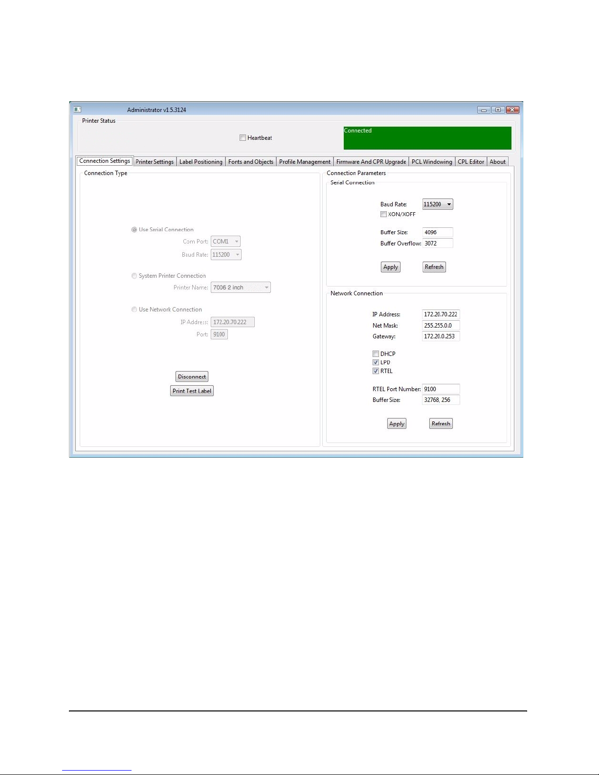
To configure the printer’s network settings, connect to the Administrator program over a
local USB or serial or parallel port. Refer to Chapter 4 “Using the Administrator Tool” for
instructions on connecting to the printer using a local port.
With the Administrator communicating with the printer over a local port, select the
Administrator’s first tab, I/O Settings, and look at the lower-right section of the screen
labeled Printer Ethernet Settings.
There are two ways to determine the printer’s address on the network. One is to assign
the printer an address by entering it in this settings window, and the other is to allow the
network to automatically assign an address to the printer.
Assigning a Static Address
To assign a static address, first obtain an address from the network administrator. In
addition to the address for the printer, the network administrator must report the proper
net mask for the network and the address of the gateway for the network.
Type the printer’s address in the IP ADDRESS field, type the net mask in the IP NET
MASK field, and type the gateway address in the IP GATEWAY field.
Select the LPD and RTEL check boxes, and deselect the DHCP checkbox. Type 9100 in
the RTEL Port Number field and type 32768 in the Ethernet Text Buffer Size field.
After typing in all the entries, click the Apply button.
Page 70
Network Printing
6-2
The screen should look like this:
Using Automatic Address Assignment
Automatic address assignment, known as DHCP configuration, is only possible if the network being used supports it. If the network does support DHCP, put the printer into
DHCP mode by selecting the DHCP checkbox under the address fields in the Ethernet
Settings area. It is not necessary to enter any addresses in the fields above.
In addition to the DHCP check box, select the LPD and RTEL check boxes. Type 9100 in
the RTEL Port Number field and type 32768 in the Ethernet Text Buffer Size field.
For the printer to receive its address from the network, it must be connected to the network when it is turned on. If the printer is not connected to the network when set to
DHCP mode, the mode setting will take effect, but the printer will not actually receive a
new address until it is connected to the network and restarted.
Page 71

Network Printing
6-3
Verifying Network Settings
When a static address was assigned or configured for DHCP, after clicking the Apply
button, disconnect the Administrator from the printer, power-cycle the printer, and then
connect to it once again using the USB, serial, or parallel port. Once the connection is
established, the Printer Ethernet Settings fields will be populated either with the
addresses entered (for static addressing) or with addresses received from the network (for
DHCP configurations.) Make note of the printer’s IP address.
Print a test label by clicking the Print Self-Test Label button at the bottom-right of the
I/O Settings tab. The network settings are printed near the end of the test label.
Once the network settings are made, disconnect the printer from the USB/serial/parallel
port (both physically and in the Administrator). It is possible to physically relocate the
printer and still be able to communicate with it as long as the printer has a network connection.
To connect to the printer using the Administrator through the network, go to the I/O Set-
tings tab and select the Network Printer method of connection. Type the IP address
assigned or received from the network, and click the Connect button. Once connected,
the Administrator functions as it did with a local connection.
Page 72
Network Printing
6-4
Configuring a Printer Driver for Network Use
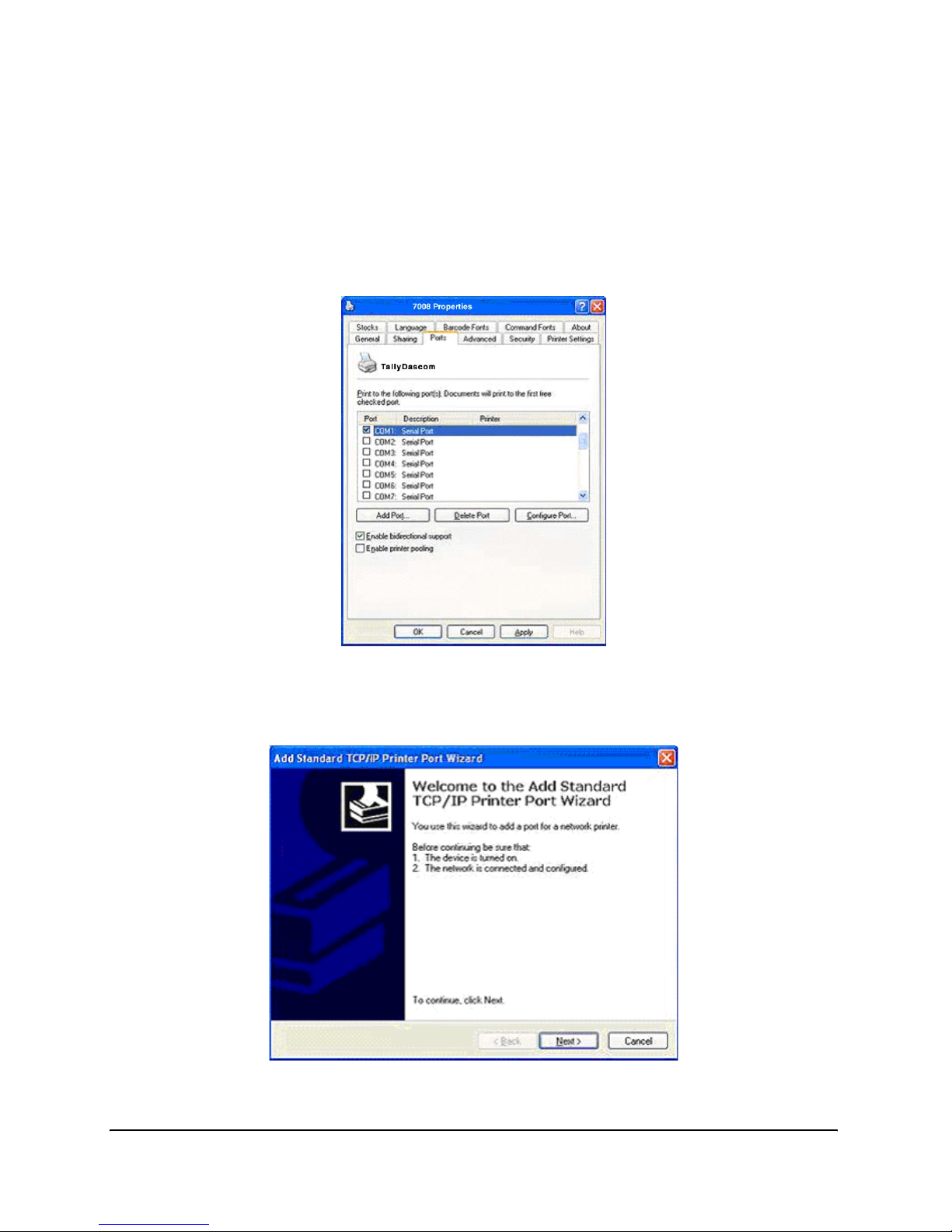
In order to print using the driver, a new port must be configured within the printer driver.
1.
Locate the appropriate driver in the Windows Printers folder.
2. Right-click on the driver and select Properties.
3. Click on the Ports tab.
4. Choose Add Port.
5. Highlight Standard TCP/IP Port and click New Port.
6. Click Next.
Page 73
Network Printing
6-5
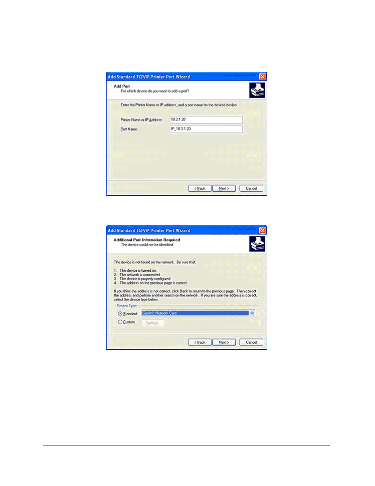
7. In the Printer Name or IP Address box, enter the IP address assigned to the
printer. The Port Name box is auto-populated. Click Next.
8. If necessary, choose Generic Network Card as shown below and then click Next.
9. Click Finished. The driver is now configured and ready to use.
Page 74
Network Printing
6-6
Sharing the Printer on a Network
ASSUMPTION: It is assumed that the printer is connected to a local machine
already on a network.
1.
Locate the appropriate Driver in the Windows Printers folder.
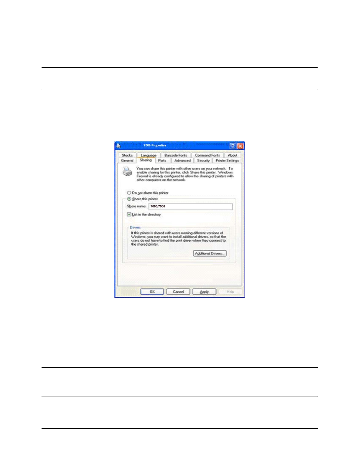
2. Right-click on the driver and select Properties.
3. Click on the Sharing tab.
4. Select Share this printer and give the printer a Share name.
5. Once a share name has been typed, click Apply.
Network Support Materials
NOTE: For more information on configuring Ethernet settings on the printer,
please refer to the Ethernet Printing Information section of the Programmer’s
Guide.
Page 75

7-1
Chapter
7
Printing Standard Labels and Tags
Sources for printed label and tag data include the following:
` Label software
` CPL programming
` Third party applications or interfaces
Using CPL Programming
A common method of printing labels is CPL programming. Commands and data are sent
to the printer using the Administrator. These commands prepare the printer to receive
the label, establish print position and characteristics, and terminate printing operation.
To begin, start the Administrator program and connect to the printer (see Chapter 4
“Using the Administrator Tool”).
After connecting to the printer, select the CPL Editor tab and enter the following text in
the Printer Input text area on the left.
! 0 100 100 1
WIDTH 224
PITCH 200
DRAW_BOX 20 0 200 30 2
TEXT 2 20 0 TEST LABEL
BARCODE CODE39 20 70 40 1234567894567
END
This series of CPL commands instructs the printer to print a simple label with text and
a barcode. To print this label, after entering the text, click the Send To Printer button
below the text area. The printer prints the following image.
Page 76

Printing Standard Labels and Tags
7-2
To save this label format for future use, click the Save to File button. To reload it, or any
other label format, click the Open File button.
For more detail on the CPL language, please refer to the CPL Programmer’s Guide.
Page 77
Printing Standard Labels and Tags
7-3
Using Third-Party and Proprietary Applications
Labels are frequently printed from commercial software or proprietary applications.
Printing from Microsoft Word
The instructions below describe how to create both simple and complex labels using
Microsoft Word software. The instructions assume the following conditions:
` The user has a basic understanding of Microsoft software and the Windows operating
system
` Printer drivers are installed correctly
` The printer is connected, powered on, and ready to print
NOTE: Examples shown here were created using Microsoft Windows XP and
Microsoft Word 2002.
To Configure the Software for the Printer
1. Open Microsoft Word.
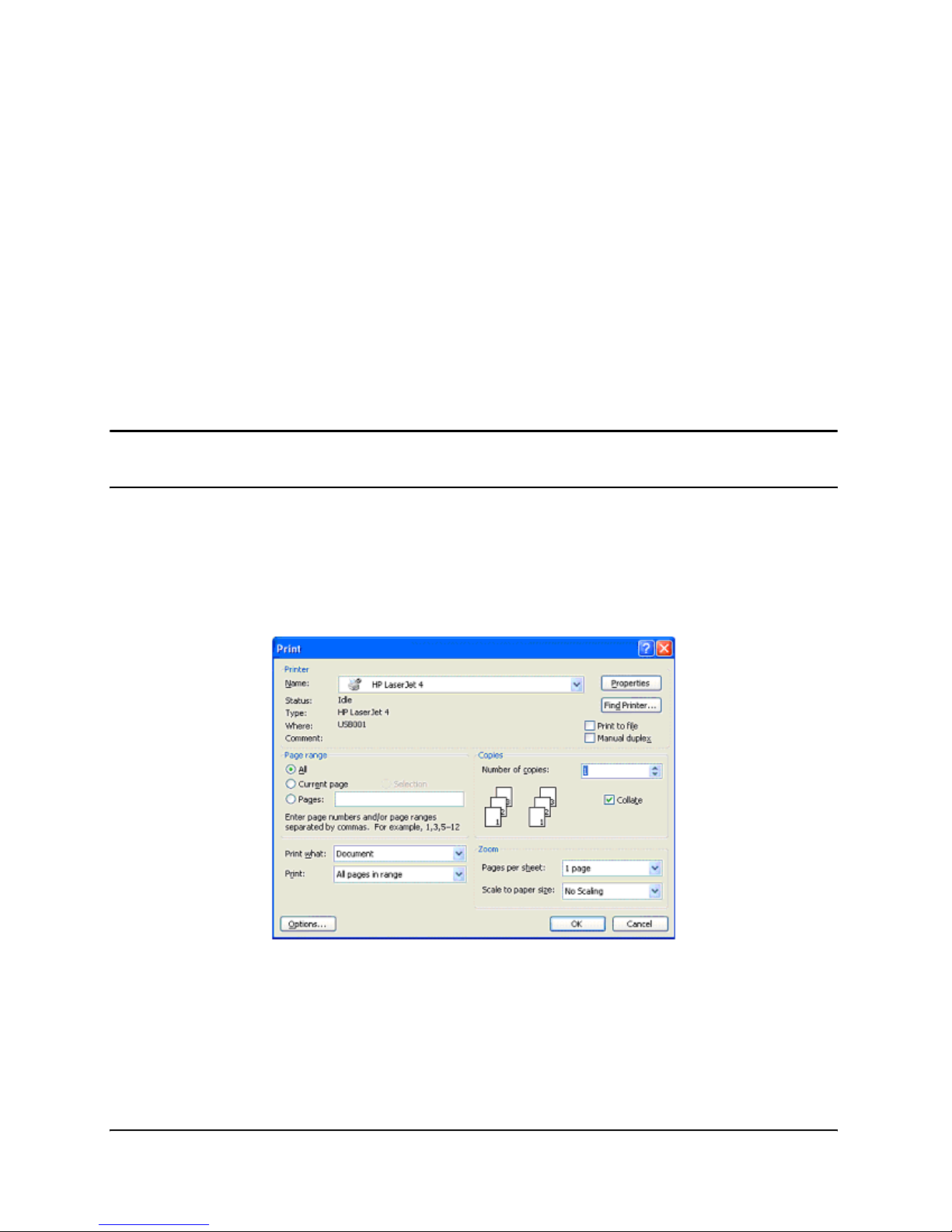
2. Press Ctrl+P or, on the File menu, choose Print. The Print dialog box appears.
Page 78
Printing Standard Labels and Tags
7-4
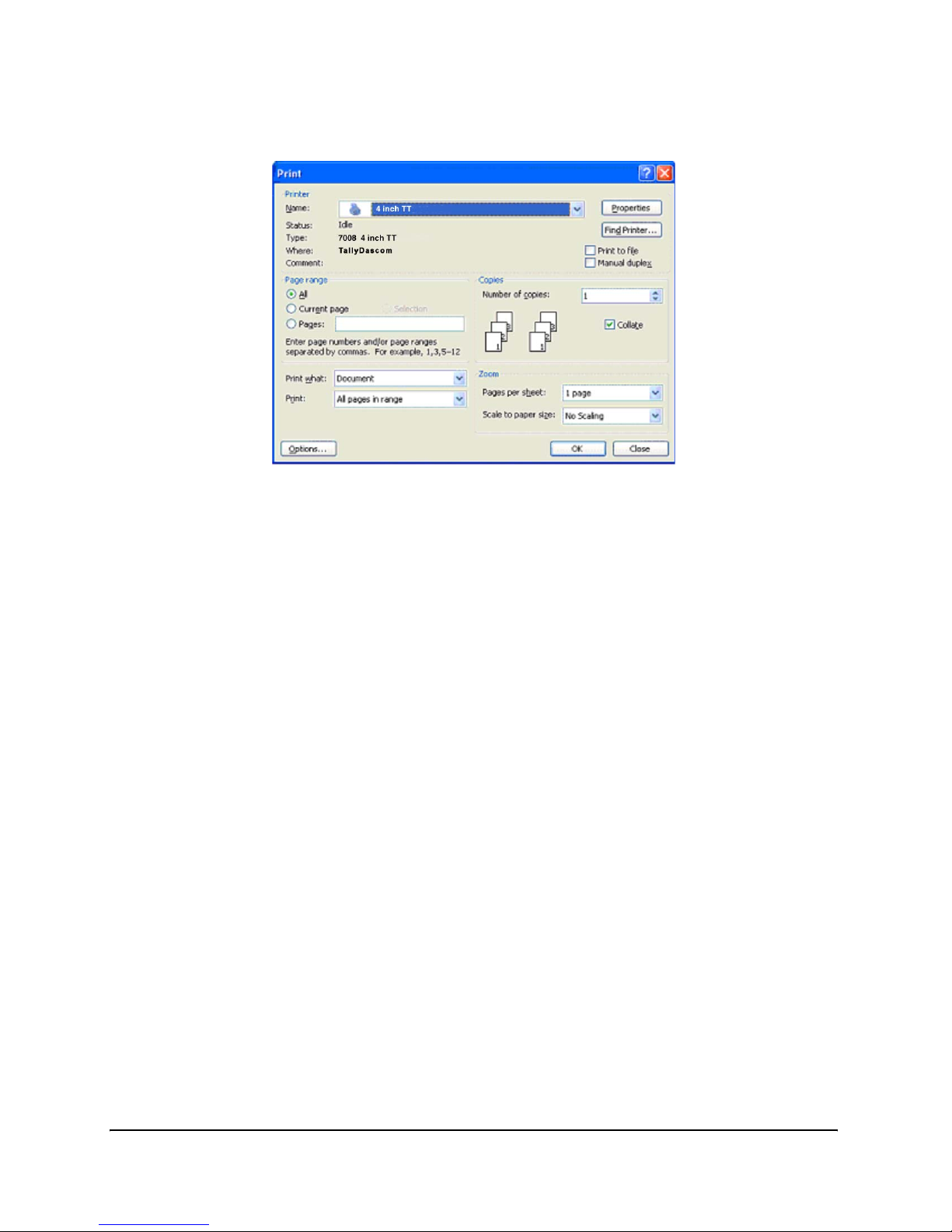
3. Select a printer.
4. Click Close to close the Print dialog box.
Page 79
Printing Standard Labels and Tags
7-5
Setting Label Size
Set up the Word document for the desired label size.
1.
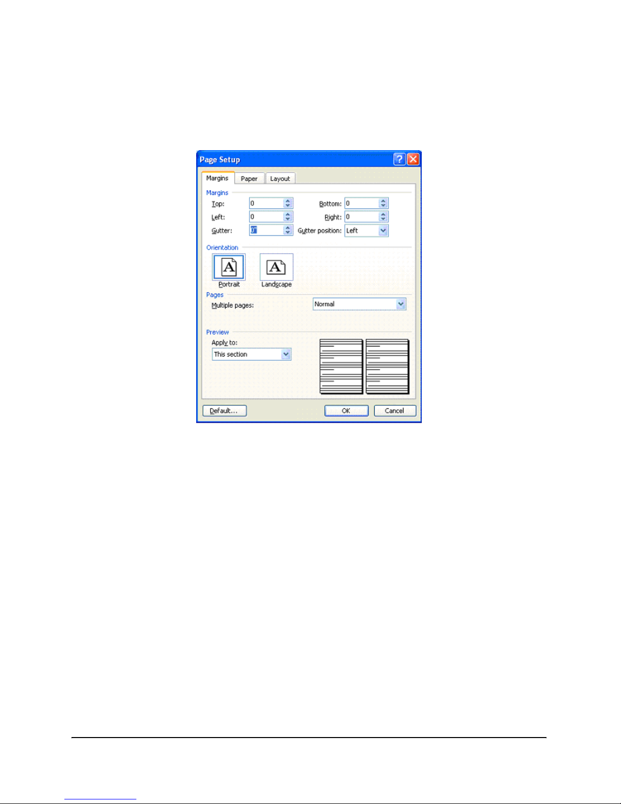
On the File menu, click Page Setup. The Page Setup dialog box displays.
2. Set all margins to 0.
Page 80
Printing Standard Labels and Tags
7-6
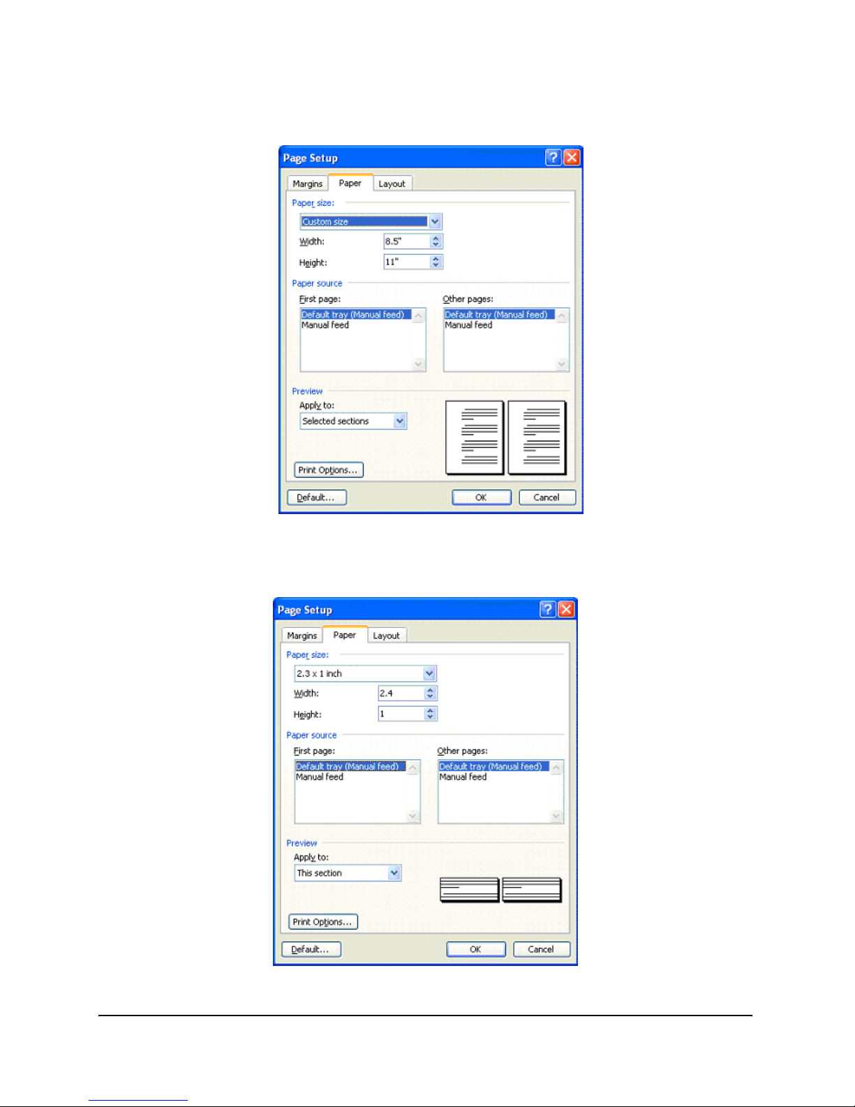
3. Click the Paper tab.
4. Set the correct width and height for the label. The example shows a 2.4” wide by 1”
tall label.
Page 81
Printing Standard Labels and Tags
7-7
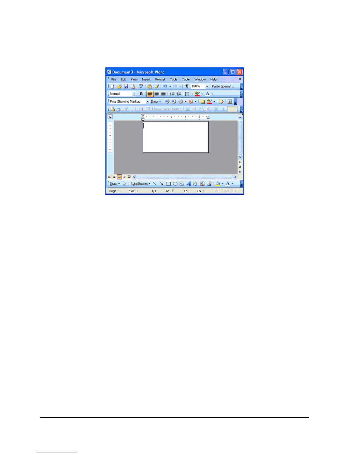
5. Click OK and, if necessary, Fix to reset the margins. The Word document should
look similar to the figure below.
Page 82
Printing Standard Labels and Tags
7-8
Creating a Label and Barcode
Design the label in a Word document. Use the following steps to design a barcode.
1.
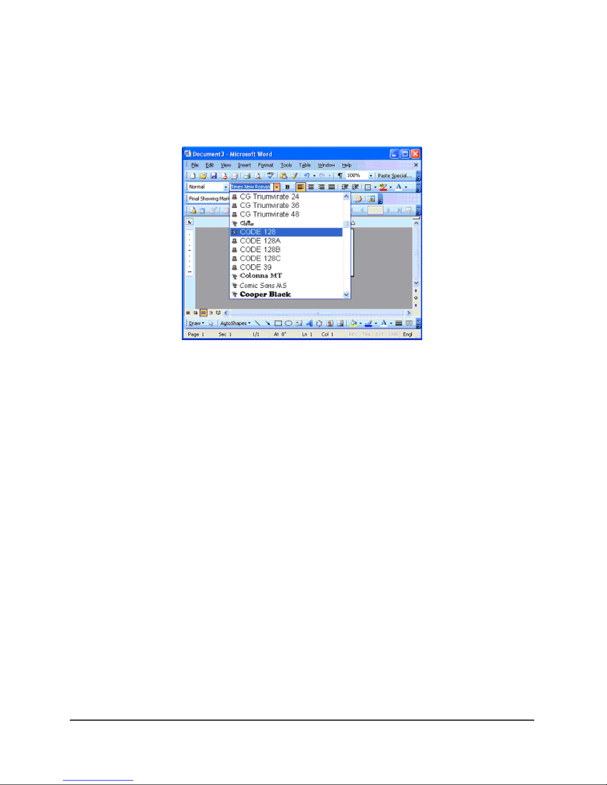
Select the desired Barcode Font/Type.
2. Enter the numbers for the barcode. A barcode will not display on the screen, but is
printed on the label.
3. Set the height of the barcode by adjusting the font size. Use trial and error to adjust
the size correctly.
Printing a Label
Make sure that the printer is connected to the computer and powered on. Ensure that the
media is loaded correctly. Use the following steps to print the label:
1.
Press Ctrl+P or, on the File menu, choose Print. The Print dialog appears.
2. Verify that the printer is selected.
3. Click OK.
Page 83

Printing Standard Labels and Tags
7-9
Printing from Proprietary Applications
There are a variety of applications that are industry or function specific. Some of these
require a generic text printer driver. Others have built-in printer drivers. Refer to the
software documentation or contact the software vendor to determine the appropriate
method for printing labels with proprietary software.
NOTE: Apart from the CPL emulation there are some other emulations available
for the printer, e.g. the ZcPL, EcPL, PcCl emulations.
Page 84

Page 85

8-1
Chapter
8
Troubleshooting
The printer requires minimal user maintenance. When problems do occur, however, it is
important to isolate the root cause between hardware or programming issues.
Isolating Problems
Programming issues can often make problems appear hardware related. Use the following steps to determine the source of the problem.
Run a Printer Self Test
A self test will help determine possible printer hardware issues since the test is performed independently from all external software, cabling, and configurations.
To perform a printer self test please refer to Chapter 2 “Performing the Self Test”.
NOTE: Leaving the printer in hex dump mode following a self test allows the
user to see every character that reaches the printer. Use of hex dump mode can
help resolve some programming problems.
If the printer will not print a self test label, the problem is most likely hardware related
and the printer will not respond to incoming data. In this case please contact technical
support.
Print a Proven Label Format
Select a label format that has previously printed successfully on the system being used.
If the proven format will not print, inspect the system for possible communication problems, for example, cables are connected properly and configuration settings are correct.
If the proven format prints successfully, then most possible hardware issues have been
eliminated.
Page 86

Troubleshooting
8-2
Print a New Label Format
If a known printable format is unavailable then a new format may be created using an
available text editor. Creating and sending the simple format listed below should help
isolate the problem.
! 0 100 120 1
TEXT 2 25 25 This is a test
END
If the printer does not print this label but does print labels that were prepared on another
system, the system being used may not be compatible with the printer. The most common
cause of this is improper end-of-line termination.
Check the Label Format Header Line
When a particular label format does not print properly or is cut off at the bottom, the
problem commonly occurs in the header line. Refer to the Programmer’s Guide header
line section before continuing.
“Comment Out” Portions of the Non-Working Label Format
Improper printer commands can be isolated by placing a "C" before selected CPL command lines. Begin by commenting out the most complex lines first and try printing the
format again. If the problem persists, try commenting out every line between the header
line and the END statement and then add lines one at a time until the problem recurs in
order to see which lines are at fault.
Once the flawed portion of the format has been isolated, reference the Programmer’s
Guide to examine the code for errors or test the co de by itse lf in a simp l ified for m at. When
examining label formats, look for instances where the letters "O" or "I" have been incorrectly entered for the numbers 0 and 1. These are very common typographical errors.
Page 87

Troubleshooting
8-3
Common Issues
The following issues are based on technical support records of user questions.
Labels Skipping or Printer Feeding Blank Labels
Label skipping can frequently be corrected by performing a printer calibration. Refer to
the calibration section of Chapter 4 (“Calibrating the Printer”).
If label skipping continues to occur, inspect the label or software application to verify the
page length being sent to the printer does not exceed the physical length of the label.
READY Light is Red
Make sure that the printhead mechanism is firmly latched into position on both sides.
Make sure that the printer is in the proper print mode and the correct accessories are
installed. Thermal Transfer printers set to TT mode create errors when printing a label
if a ribbon is not installed.
If the printer feeds out multiple blank labels, it needs to be calibrated. Refer to the calibration section of Chapter 4 (“Calibrating the Printer”).
Make sure that the correct power supply for the printer is being used. The printer uses a
90-264VAC output power supply. The output voltage is printed on the power supply.
Printer Drivers
Printer drivers are available for download from the manufacturers web site. For more
information on where to download printer drivers please reference Chapter 3 “Windows
Driver Installation” part of this User’s Guide.
Setting Up an Ethernet Printer
Download the Administrator Configuration tool for easy access to setting these values
from the Installation CD included with the printer or from the manufacturers web site.
These settings can also be configured by connecting the printer to a PC using the parallel
or serial port (Refer to Chapter 2 “Connecting Data Cables to the Printer”for details
regarding parallel or serial port set up).
Type in the following commands to a text editor on the computer:
! 0 0 0 0 (Must use zero; space between each character)
VARIABLE ETHERNET IP xxx,xxx,xxx,xxx
VARIABLE NETMASK xxx,xxx,xxx,xxx
VARIABLE GATEWAY xxx,xxx,xxx,xxx
VARIABLE WRITE
VARIABLE ETHERNET RESET
END
Page 88

Troubleshooting
8-4
Send this file to the printer by selecting File then selecting Print. The printer will not
print anything but the ready light will blink on and off. Once a solid Green ready light is
visible, cycle the power to the printer. To verify the settings have taken effect, perform a
self test and verify the settings are now set in the printer. For more instructions on performing a self test, please refer to Chapter 2 “Performing the Self Test” of this User’s
Guide.
Serial Communication
If a serial port will be used for printing to the printer, a custom null-modem serial cable
from the manufacturer is required. Refer to the accessories section listed in Chapter 10
“Consumables” or the Printer Product Guide for ordering information.
The default serial communications settings are: 9600, N, 8, 1.
Parallel Communication
If a parallel port will be used for printing to the printer, a custom uni-directional cable
from the manufacturer is required. Refer to the accessories section listed in Chapter 10
“Consumables” or the Printer Product Guide for ordering information.
When printing in parallel the port must be set up as an LPT port, not an ECP port. If the
port is configured as ECP, printing may be inconsistent.
Page 89

Troubleshooting
8-5
Printing Too Light
Download and install the Administrator configuration software for simplified setting of
these values from the Installation CD included with the printer or from the manufacturers web site. These values may be changed using the Printhead Darkness setting
located in the Printer Settings tab.
If unable to use the Administrator to configure this setting, type the following commands
into a text editor on the computer:
! 0 0 0 0 (Must use zero; space between each)
VARIABLE DARKNESS ##
VARIABLE WRITE
END
The ## indicates the desired value to which the Darkness will be set. This should be a
value slightly larger than the original one in order to increase the darkness.
For example, type the line as VARIABLE DARKNESS 20. Continue to gradually increase
the number to 30, 40, 50, and so on until the desired darkness is achieved. The higher the
number the darker the print will be.
Send this file to the printer by selecting File then selecting Print. The printer will not
print anything but the ready light will blink on and off. Once a solid Green ready light is
visible, cycle the power to the printer. To verify the settings have taken effect, perform a
self test and verify the settings are now set in the printer. For more instructions on performing a self test, please refer to Chapter 2 “Performing the Self Test” of this User’s
Guide.
General Troubleshooting Tips
Equipment and Cabling
Make sure that all cables and connectors are installed and secure. Before printing, make
sure there is media in the printer and the power and ready green lights are illuminated.
If the printer is a thermal transfer unit it requires ribbon to print, and a ribbon will need
to be installed in the printer.
Printing a Diagnostic or Self Test Page
Please refer to Chapter 2 of this User’s Guide, to the section on “Performing the Self Test”
for full detailed instructions.
Cleaning the Printhead
Refer to Chapter 11 of this User’s Guide, “Cleaning and Preventive Maintenance”.
Page 90

Troubleshooting
8-6
Paper is Jammed in the Printer
Turn the printer off before attempting to un-jam the printer. If a label is jammed in the
printer, unplug the printer from its power source and remove the jammed label by hand
only. If needed, clean any remaining adhesive on the printer with a lint-free cloth, and
98% to 99 % pure isopropyl or denatured alcohol. Refer to Chapter 11: “Cleaning Instructions” for more information regarding suggesting cleaning and preventive maintenance.
NOTE: Do not use blades, sharp tools, etc. to prevent damage to the rubber
platen.
Tips for Avoiding Paper Jams
Make sure the roll of media is aligned in the center of the printer and the printer’s spring
loaded media guides are firmly pressed against both sides of the roll.
Blank Label is Printing
Make sure all cables and connectors are installed and secure. Before printing, make sure
media is loaded into the printer and both the power and ready green lights are on. If the
printer is a thermal transfer unit it requires ribbon to print, and a ribbon will need to be
installed in the printer.
Page 91

9-1
Chapter
9
Printer Specifications
Specifications are provided for reference and are based on printer tests using Tally Dascom brand ribbons and labels. Results may vary in actual application settings or when
using products other than recommended supplies. We recommend always qualifying any
application with thorough testing. For updated technical specifications please visit us
online at:
http://jadmin.dascom.com
Technical Specification Information
Standard Features
` Compact printer design, small footprint high performance
` Administrator Configuration Software
` Bi-directional USB Drivers
` LCD control panel: Back-lit, 2 line, 16 characters (7008 only)
` 200 MIPS, 180MHz, 32 bit RISC Processor
` 16 MB SDRAM memory
` 8 MB flash memory for firmware and stored objects.
` Hinged media cover to accommodate oversized rolls
` Double clamshell design for easy access user setup menus, easy ribbon loading and sim-
ple media loading.
` Rugged die-cast metal user interface.
` Audible indicator for error warning or document alert.
` Wide path indexing sensor range.
` 203 dpi print resolution (8 dots/mm)
` 2” and 4” Print width models
Page 92

Printer Specifications
9-2
` Upgradeable firmware and stored objects
` Direct thermal printing
` CPL programming language
` Parallel, Serial, USB-A, and USB-B communication ports
` USB-A Host Control available early November 2006
` Adjustable position transmissive and reflective index sensing technology to accommo-
date a wide variety of print media.
` Printer driver for Windows™ NT, 2000, XP and Windows 7 operating systems.
Optional Features
` 300 dpi Print Resolution (12 dots/mm)
` Ethernet 10/100 Base-T interface
` Thermal Transfer Printing
` PCL (4” printers with 300 dpi printhead only)
Printing Specifications
Nominal
Printer Size
2” 7006 or 7008 4” 7006 or 7008
Print
Resolutions
203 dpi Standard 300 dpi Optional 203 dpi Standard 300 dpi Optional
Max Print
width
2.118" (53.8mm) 2.205" (56.0mm) 4.094" (104.0mm) 4.153" (105.5mm)
Print Speeds 7006: 4-6 ips
7008: 4-8 ips
7006: 2-6 ips
7008: 2-6 ips
7006: 4-6 ips
7008: 4-8 ips
7006: 2-6 ips
7008: 2-6 ips
Max Print
Lengths
322” (8179mm) 218” (5537mm) 322” (8179mm) 153” (3886mm)
Print Position
Tolera nce
±0.0625" (1.6mm) Left and right
Page 93

Printer Specifications
9-3
Media Specifications
Media Types: Direct thermal or thermal transfer labels, tags, wristbands, static labels,
and receipt paper.
Media Thickness: 0.010” (0,25mm) thickness max.
Index types: Reflective and transmissive sensors to detect gaps between labels, die-cuts,
black-marks, notches, and holes.
Media Format: Continuous fanfold (external) or roll with optional inter-sheet perforations for easy media separation.
Media Web Width (label and liner):
` 2” Printer: 0.5” (12.7mm) to 2.84” (72mm)
` 4” Printer: 2.4" (60.96mm) to 4.63" (117.6mm)
` Minimum label length: 0.375” (9.5mm) with .125” gap
` Maximum media roll size: 7.750" (194mm) O.D. on a 1.5" (38.1mm) ID. Core
Media Indexing
Indexing Sensing Methods: None, gap, bar, notch, and hole.
Gap and notch sensing standards: Minimum Inter-label gap: 0.125” (3.18mm)
Gap Sensing Width Range:
` 2” Printer: User adjustable 1” right of center to 1.2” left of center.
` 4” Printer: User adjustable from center to 2.2” left of center.
Black mark sensing standards: Black mark length (parallel to inside media edge):
0.125”(3.18mm)- 1.0”(2.54mm)
Black Mark Sensing Range: User adjustable in increments of 0.2” left and right to
within 0.5” of edge of the maximum media web width.
Page 94

Printer Specifications
9-4
Ribbon Specifications
Ribbon width:
` 2” Printer: 2.4" (61mm) Max.
` 2” Nominal Length: 6500” (approx. 165m) Max.
` 4” Printer: 4.25" (108mm) Max.
` 4” Nominal Length: 6500” (approx. 140m) Max.
Types: Available in Wax, Wax/Resin, and Premium Resin varieties
Label Roll Changes per Ribbon
7” Label Roll OD = equivalent to 8” Roll
Font Specifications
Bitmapped: 7 styles with up to 10x10 magnification, variable boldness and spacing.
International AGFA Fonts: Sans-serif font in 7 pt. sizes, up to 4x4 magnification, vari-
able boldness and spacing.
Scalable Vector Fonts: 3 ultra font styles for smooth characters in any size and boldness.
Rotations: 0, 90, 180, 270 degrees
Label Roll OD Label Roll ID 2” Label Rolls per
Ribbon Roll
4” Label Rolls per
Ribbon Roll
5” 1.5” 2.4 2
7” 1.5” 1 .85
Page 95

Printer Specifications
9-5
Bar Code Symbologies and Specifications
Programming Language (CPL)
` Communicates in printable ASCII characters
` Compatible with mainframe, mini, and PC hosts
` Downloadable objects include graphics and bitmap fonts
` Automatic serialization of fields
` Format inversion (white on black)
` Four position field rotation (0°, 90°, 180°, 270°)
` Programmable label quantities with print and pause control
` Status messages to host upon request
UPCA ADD 2 EAN 8 128C
UPCE ADD 5 EAN 13 CODE128
UPCE1 CODE 39 PLESSEY EAN128
POSTNET I 2OF5 128A CODABAR
Maxicode mode 0 CODE 93 128B MSI
PDF417 DataMatrix QR Code Aztec
UPCA+ MSI1 S20F5 D20F5
RSS
Page 96

Printer Specifications
9-6
Communications Specifications
Parallel Interface: Centronics compatible parallel interface (requires a special cable).
High-speed serial interfaces:
` Serial RS-232 (requires a special cable)
` Configurable baud rate (1,200 – 115,200 baud), parity, and data bits. Stop bits at 1 or 2.
` Software (XON/XOFF) or hardware (DTR/DSR) communication handshake protocols
` USB 2.0 compatible interface
` Ethernet 10/100 Base-T interface, Cat 5e cable (Optional)
Electrical Specifications
` Auto-detectable 90-264VAC, 24VDC 150W power supply
International Environment Compliance
Compliant with the following international environmental directives:
` Directive 2002/95/EC on the restriction of Use of certain Hazardous Substances in Elec-
trical and Electronic Components (RoHS)
` Directive 2002/96/EC on Waste Electrical and Electronic Equipment (WEEE)
International Regulatory Compliance
` Printer and Power Supply: UL, FCC Class A, CCC, CE, CiSPR22/CB.
` Power Supply Only: CSA GS/TUV/VDE/PSE
Environmental Specifications
Operating environment: 41° to 104°F (5° to 40°C) 20% to 85% non-condensing R.H.
Page 97
Printer Specifications
9-7
Physical Specifications
Software
Administrator: Printer with USB/Serial bi-directional configuration software, included
with printer requires Windows driver installation.
Clean Driver Utility: Self contained driver cleanup utility that entirely removes old
drivers.
Windows™ OS Drivers: Printer drivers that allow applications running on Windows
operating systems to print to the printer.
Preventive Maintenance
We recommend cleaning the printer on a regular basis using standard cleaning supplies.
Cleaning
The exterior is cleaned with a lint-free cloth, and if necessary, a mild detergent solution
in a damp cloth. It is recommended that interior components are cleaned with authorized
cleaning supplies every 20,000 inches (508 m) or blown air to remove any particles. The
printhead should be cleaned every 5000 inches if preprinted labels are used. The platen
should be cleaned at the same interval, using the same cleaning materials as applied to
the printhead. Please refer to Chapter 11 “Cleaning and Preventive Maintenance” for
more details on cleaning the printer.
Characteristic 2” Printer 4” Printer
Height 7.1” (181mm) 7.1” (181mm)
Width 5” (127mm) 6.9” (175mm)
Depth 10.04” (255mm) 10.04” (255mm)
DT Weight 5.02 lbs (7008) 4.91 lbs (7006) 5.91 lbs (7008) 5.88 lbs (7006)
TT Weight 5.23 lbs (7008) 5.00 lbs (7006) 6.10 lbs (7008) 6.00 lbs (7006)
Page 98

Page 99

10-1
Chapter
10
Consumables
Compatible Media
The manufacturer stocks a wide variety of labels and tags for use in thermal printers.
Items range from paper labels and tags in various sizes and synthetic jewelry labels to
RFID labels and hospital wristbands.
If the standard items will not fit your application needs, the manufacturer offers custom
options for compatible labels and tags.
The manufacturer offers a full range of printing capabilities, from sequential numbering
and barcodes to full-color labels.
The manufacturer uses only the highest-quality facestocks and adhesives. A wide range
of paper, cardstock and synthetic/film materials for thermal printers, along with specialized materials. Adhesives ranging from super-aggressive to ultra-removable, plus specialty adhesives that can withstand extreme.
The manufacturer has a full selection of inks and specialty dyes that can be matched to
any color with superior lamination and varnish options.
Consumables
Please contact a local reseller, or contact the manufacturer for information on media and
consumable parts.
Page 100

Consumables
10-2
DT Inch Labels and Tags
Size
(WxH”)
# up
Print
type
Material Adhesive Wind OD” Core”
Items
per roll
Rolls per
case
Index
Stock
Item
Roll # Part #
.75x.75 1 DT Paper Permanent In 4.75 1.5 2285 12 Gap N 03-02-1825
1.15x1 1 DT Paper Permanent In 4.75 1.5 1685 12 Gap N 03-02-3004
1.15x1 2 DT Paper Permanent In 4.75 1.5 3370 12 Gap N 03-02-1520
1.15x1 2 DT Paper Permanent In 4.75 1.5 3370 12 Bar N 03-02-1545
1.15x1 2 DT Paper Removable In 4.75 1.5 3370 12 Gap N 03-02-1897
1.15x1 2 DT Paper Permanent In 5 1.5 4700 12 Gap N 03-02-2100
1.15x1 2 DT Paper Removable In 5 1.5 4700 12 Gap N 03-02-2101
1.15x1 2 DT Paper Permanent In 7 1.5 10610 6 Gap N 03-02-2590
1.15x1 2 DT Paper Removable In 7 1.5 10610 6 Gap N 03-02-2588
1.2x1 2 DT Paper Removable In 4.75 1.5 3370 12 Bar N 03-02-1150
1.2x1 2 DT Paper Permanent In 4.75 1.5 3370 12 Bar N 03-90-1045
1.5x1 1 DT Paper Permanent In 2 1.5 255 36 Gap N 03-02-2606
1.5x1 1 DT Paper Permanent In 3 1.5 880 36 Gap N 03-02-2607
1.5x1 1 DT Paper Permanent In 3.5 1.5 750 12 Bar N 03-89-1041
1.5x1 1 DT Vinyl Permanent In 3.5 1.5 750 12 Bar N 03-89-1037
1.5x3 1 DT Paper Permanent In 3.5 1.5 280 12 Bar N 03-89-1040
1.5x3 1 DT Vinyl Permanent In 3.5 1.5 280 12 Bar N 03-89-1036
2x.56 1 DT Paper Permanent In 4.75 1.5 2665 12 Gap N 03-02-3006
2x0.56 1 DT Paper Permanent In 4.75 1.5 2665 12 Bar N 03-02-1368
2x1 1 DT Paper Permanent In 3 1.5 880 36 Gap N 03-02-2611
2x1 1 DT Vinyl Permanent In 2 1.5 255 36 Gap N 03-02-2624
2x1 1 DT Vinyl Permanent In 3 1.5 880 36 Gap N 03-02-2625
2x1.25 1 DT Paper Permanent In 2 1.5 210 36 Gap N 03-02-2612
2x1.25 1 DT Paper Permanent In 3 1.5 720 36 Gap N 03-02-2613
2x2 1 DT Paper Permanent In 3 1.5 465 36 Gap N 03-02-2615
2x3 1 DT Paper Permanent In 3 1.5 310 36 Gap N 03-02-2617
2.3x1 1 DT Paper Permanent In 5 1.5 2350 12 Gap N 03-02-2102
2.3x1 1 DT Paper Removable In 7 1.5 5305 6 Gap N 03-02-2566
2.3x1 1 DT Paper Permanent In 7 1.5 5305 6 Gap N 03-02-2586
2.3x1 1 DT Paper, yellow Permanent In 4.75 1.5 1685 12 Gap N 03-02-3002
2.3x1 1 DT Paper Permanent In 4.75 1.5 1685 12 Gap N 03-02-1519
2.3x1 1 DT Paper Permanent In 4.75 1.5 1685 12 Bar N 03-89-1006
2.4x.75 1 DT Vinyl Permanent In 5 1.5 2880 12 Gap N 03-02-2111
2.4x.75 1 DT Vinyl Permanent In 4.75 1.5 2130 12 Gap N 03-02-1648
 Loading...