

Page 1

Tally Dascom 1140
Mantenimiento Periféricos Informáticos SL C/Canteras, 15 28860 Paracuellos de Jarama Tel: 00 34 917481604 WEB: https://mpi.com.es
I
Page 2

Tally Dascom 1140
Mantenimiento Periféricos Informáticos SL C/Canteras, 15 28860 Paracuellos de Jarama Tel: 00 34 917481604 WEB: https://mpi.com.es
Page 3

Tally Dascom 1140
Mantenimiento Periféricos Informáticos SL C/Canteras, 15 28860 Paracuellos de Jarama Tel: 00 34 917481604 WEB: https://mpi.com.es
Important Safety Instructions (English)
Read the following instructions thoroughly before starting up your printer.
Never carry out maintenance or repair work yourself. Always contact a qualified service technician.
Keep this Operator’s Manual in a place which is easily accessible at all times.
Place the printer on a solid and even base so that it cannot fall.
Never place the printer in the vicinity of inflammable gas or explosive substances.
Ensure the printer is connected to a socket with the correct mains voltage.
Always disconnect the printer from the mains before opening the device to perform maintenance work or
remedy errors.
Do not expose the printer to high temperatures, direct sunlight or dust.
Keep all liquids away from the printer.
Protect the printer from shock, impact and vibration.
Make sure that the printer and computer are switched off before connecting the data cable.
The print head will become very hot during printing; avoid contact with the print head after printing has
finished.
Do not perform any operation or action in any way other than those provided in this manual. When in
doubt, contact your dealer or your customer support.
The device and mains-socket must all times be easily accessible.
I
Page 4

Tally Dascom 1140
Mantenimiento Periféricos Informáticos SL C/Canteras, 15 28860 Paracuellos de Jarama Tel: 00 34 917481604 WEB: https://mpi.com.es
Wichtige Sicherheitshinweise (German)
Lesen Sie bitte diese Sicherheitshinweise durch, bevor sie den Drucker in Betrieb nehmen.
Führen Sie Wartungsarbeiten und Reparaturen keinesfalls selbst aus, sondern verständigen Sie immer
einen qualifizierten Servicetechniker.
Bewahren Sie diese Dokumentation an einem jederzeit zugänglichen Ort auf.
Den Drucker auf stabilem und ebenem Untergrund so aufstellen, dass er nicht zu Boden fallen kann.
Stellen Sie den Drucker keinesfalls in der Nähe von leicht entzündlichen Gasen oder explosiven Stoffen
auf.
Den Drucker nur an eine Steckdose mit der richtigen Spannung anschließen.
Wenn Sie den Drucker vom Netz trennen wollen, den Drucker ausschalten und immer den Netzstecker
an der Steckdose ziehen.
Den Drucker weder hohen Temperaturen noch direktem Sonnenlicht und Staub aussetzen.
Keine Flüssigkeiten mit dem Drucker in Berührung bringen.
Den Drucker keinen Erschütterungen, Stößen oder Vibrationen aussetzen.
Sicherstellen, dass der Drucker und der Computer ausgeschaltet sind, bevor das Datenkabel
angeschlossen wird.
Der Druckkopf wird während des Druckens heiß. Vor dem Berühren deshalb einige Zeit abkühlen lassen.
Weichen Sie bei der Bedienung des Druckers nicht von den Anweisungen in der Dokumentation ab.
Bei Unklarheiten wenden Sie sich bitte an Ihren Händler oder Ihren Kundendienst.
Maschinenlärminformations – Verordnung – 3.GPSGV, der höchste Schalldruckpegel beträgt 70 dB(A)
oder weniger gemäß EN ISO 7779.
Das Gerät und die Netzsteckdose müssen jeder Zeit leicht zugänglich sein.
II
Page 5

Tally Dascom 1140
Mantenimiento Periféricos Informáticos SL C/Canteras, 15 28860 Paracuellos de Jarama Tel: 00 34 917481604 WEB: https://mpi.com.es
Consignes importantes de sécurité (French)
Lire attentivement les instructions suivantes avant de mettre l’imprimante en service.
Ne jamais effectuer soi-même les travaux d’entretien et de réparations. Contacter toujours un
dépanneur qualifié.
Placer l’imprimante sur un support stable de façon à ce qu’elle ne puisse pas tomber.
Ne jamais placer l’imprimante à proximité de sources de gaz aisément inflammables ou de substances
explosives.
Ne connecter l’imprimante à une prise que lorsque la tension est correcte.
Pour déconnecter l’imprimante de l’alimentation principale, mettre l’imprimante hors tension et toujours
débrancher le connecteur secteur de la prise murale.
Ne pas exposer l’imprimante à des températures élevées, à la lumière directe du soleil ou à la poussière.
Ne pas mettre l’imprimante en contact avec des liquides.
Ne pas exposer l’imprimante à des chocs, impacts ou vibrations.
S’assurer que l’imprimante et l’ordinateur sont hors tension avant de connecter le câble de données.
La tête d’impression est brûlante pendant l’impression. C’est pourquoi laissez-la refroidir quelques
instants avant d’y toucher.
N'exécutez aucune opération ni action d'une autre manière que celle indiquée dans ce manuel. En cas
de doute, veuillez contacter votre distributeur ou service après-vente.
Le dispositif et la prise principale doivent toujours être accessibles facilement.
III
Page 6

Tally Dascom 1140
Mantenimiento Periféricos Informáticos SL C/Canteras, 15 28860 Paracuellos de Jarama Tel: 00 34 917481604 WEB: https://mpi.com.es
Indicazioni di sicurezza importanti (Italian)
Prima di mettere in funzione la stampante, leggere attentamente le seguenti indicazioni.
Non eseguire mai da sé gli interventi di manutenzione e riparazione, ma rivolgersi sempre a un tecnico
di assistenza qualificato.
Conservare le presenti istruzioni per l’uso in un luogo sempre accessibile.
Collocare la stampante su una superficie stabile, per evitare che cada a terra.
Non collocare la stampante in prossimità di gas facilmente infiammabili o di sostanze esplosive.
Collegare la stampante a una presa di corrente con tensione adeguata.
Per scollegare la stampante dalla rete di alimentazione, spegnere la stampante e disinserire sempre il
connettore di rete dalla presa.
Non esporre la stampante ad elevate temperature né alla luce solare diretta e alla polvere.
Evitare il contatto della stampante con liquidi.
Non esporre la stampante a colpi, scosse o vibrazioni.
Verificare che la stampante e il computer siano spenti prima di collegare il cavo di trasmissione dati.
Durante la stampa, la testina si surriscal-da notevolmente. Prima di toccarla, se necessario opportuno
quindi lasciarla raffreddare qualche istante.
Non eseguire alcuna operazione o azione se non nella maniera descritta nel presente manuale. In caso
di dubbio, contattare il rivenditore o dalla società incaricata dell’assistenza.
Il dispositivo e la presa di corrente devono essere sempre facilmente accessibili.
IV
Page 7

Tally Dascom 1140
Mantenimiento Periféricos Informáticos SL C/Canteras, 15 28860 Paracuellos de Jarama Tel: 00 34 917481604 WEB: https://mpi.com.es
Instrucciones de seguridad importantes (Spanish)
Lea las siguientes instrucciones con esmero antes de poner la impresora en servicio.
Nunca lleve a cabo trabajos de mantenimiento o reparación Ud. mismo, sino consulte a un técnico de
servicio calificado.
Guarde las presentes instrucciones de servicio en un lugar de fácil acceso en cualquier momento.
Ponga la impresora sobre un base estable de manera que no pueda caer al suelo.
Nunca coloque la impresora en la vecindad de gases de fácil inflamabilidad o sunstancias explosivas.
Asegure conectar la impresora sólo a un enchufe con un voltaje correcto.
Cuando quiera desconectar la impresora de la red, apague la impresora y siempre tire la clavija de
alimentación del enchufe.
No exponga la impresora a temperaturas altas, a la luz solar directa y al polvo.
No ponga la impresora en contacto con fluidos.
Nunca exponga la impresora a sacudidas, choques o vibraciones.
Asegúrese de que la impresora y el ordenador estén apagdos antes de conectar el cable de datos.
La cabeza de impresión se pone muy caliente durante la impresión. Por lo tanto, deje enfriarlo algún
tiempo antes de tocarla.
No permita que se realice cualquier operación o acción de una forma diferente a lo que se señala en el
manual. En caso de duda, póngase en contacto con su comerciante o con su servicio post-venta.
El dispositivo y la toma de corriente deben estar ubicados de forma que sea fácil acceder a ellos.
V
Page 8

Tally Dascom 1140
Mantenimiento Periféricos Informáticos SL C/Canteras, 15 28860 Paracuellos de Jarama Tel: 00 34 917481604 WEB: https://mpi.com.es
Правила по технике безопасности. (Russian)
Прочитайте, пожалуйста, инструкцию по технике безопасности перед включением в работу принтера.
Не выполняйте технические работы и ремонт техники самостоятельно, но сообщайте о
неисправностях квалифицированным сервисным техникам.
Данная инструкция должна быть всегда доступна каждому пользователю.
Установите принтер на ровном и стабильном месте так, чтобы он не смог упасть на пол.
Ни в коем случае не ставьте принтер вблизи легко воспламеняющихся газов и взрывчатых
веществ.
Включайте принтер в розетку только с соответствующим напряжением.
Если Вы хотите отключить принтер от напряжения, сначала выключите принтер сам и затем
выньте штекер из розетки.
Берегите принтер от нагревания, от попадания на него прямых солнечных лучей и пыли.
Не допускайте попадания жидкости на принтер.
Нельзя подвергать принтер тряске, ударам и вибрации.
Убедитесь, что принтер и компьютер выключены, только после этого соедините принтер с
компьютером.
Печатающая головка нагревается во время работы принтера. Поэтому подождите какое-то время,
прежде чем дотронуться до нее.
Пользуйтесь принтером так, как это написано в документации. Если у Вас возникают неясности,
обращайтесь с вопросами к Вашим продавцам или в сервисный центр.
Устройство и розетка должны быть всегда легко доступна.
VI
Page 9

Tally Dascom 1140
Mantenimiento Periféricos Informáticos SL C/Canteras, 15 28860 Paracuellos de Jarama Tel: 00 34 917481604 WEB: https://mpi.com.es
Instruções Importantes sobre Segurança (Portuguese)
Leia as instruções de segurança antes de usar a impressora.
Consulte sempre um técnico qualificado para executar uma reparação .
Coloque a impressora sobre uma base sólida e nivelada, para que ela não sofra quedas.
Jamais instale a impressora nas proximidades de lugares onde haja gás inflamável ou substâncias
explosivas.
Assegure-se de conectar a impressora à tomada elétrica com a voltagem apro-priada.
Quando desligar a impressora da rede, desligue sempre a impressora e retire o cabo da tomada.
Não exponha a impressora a temperaturas altas ou luz solar direta.
Não aproxime substâncias líquidas da impressora.
Proteja a impressora de choques, impactos e vibrações.
Desligue a impressora e o computador antes de conectar o cabo da rede.
A cabeça da impressora pode ficar muito quente . Portanto, espere algum tempo antes de tocá-la.
Não faça nenhuma operação ou ação além das recomendadas neste manual. Em caso de dúvida,
contate seu revendedor ou companhia de serviço.
A impressora e a tomada devem ser facilmente em todos os momentos acessíveis.
VII
Page 10

Tally Dascom 1140
Mantenimiento Periféricos Informáticos SL C/Canteras, 15 28860 Paracuellos de Jarama Tel: 00 34 917481604 WEB: https://mpi.com.es
Önemli Güvenlik Talimatları (Turkish)
Lütfen, yazıcıyı işletime geçirmeden önce bu güvenlik talimatlarını bütünüyle dikkatle okuyun.
Bakım ve tamir çalışmalarını kesinlikle ve hiçbir surette kendi başınıza yapmayın; her zaman kalifiyebir
uzman servis-teknisyenine haber verin.
Yazıcıyı, üzerinden yere düşmesi mümkün olmayacak sabit ve düz bir zemine yerleştirin.
Yazıcıyı kesinlikle ve hiçbir surette kolayca yanabilecek gaz veya patlayıcı maddeler içeren nesnelerin
yakınına koymayın.
Yazıcı akım kablosunu sadece doğru gerilime sahip bir prize takın.
Yazıcıyı şebeke ağından ayırmak istediğinizde, yazıcıyı kapatın ve ağ-fişini her zaman prizden çıkartın.
Yazıcıyı ne yüksek ısılı ne de doğrudan güneş ışığına ve toza mâruz kalan mekânlarda bulundurun.
Yazıcı hiçbir sıvı maddeyle temasta olmamalıdır.
Yazıcı hiçbir sarsıntıya, darbeye veya titreşime mâruz kalmamalıdır.
Veri kablosu bağlanmadan önce hem yazıcının hem de bilgisayarın kapalıolduklarından emin olmalısınız.
Yazıcının başı basma esnasında yüksek ısıya ulaşıyor. Bu yüzden lütfen dokunmadan önce kısa süre
soğumasını bekleyin.
Yazıcının işletimi ve kullanımında bu dokümantasyondaki talimatların hiç dışına çıkmayın. Sorunlu
görünen hususlarda lütfen imâlatçınıza veya müşteri hizmetleri servisinize başvurun.
Cihaz ve elektrik prizinin her zaman kolayca erişilebilir olması gerekir.
VIII
Page 11

Tally Dascom 1140
Mantenimiento Periféricos Informáticos SL C/Canteras, 15 28860 Paracuellos de Jarama Tel: 00 34 917481604 WEB: https://mpi.com.es
TRADEMARK ACKNOWLEDGEMENTS
“IBM” is a trademark of International Business Machines Corporation.
“EPSON” is a trademark of Epson America Incorporated.
“DEC” is a trademark of Digital Equipment Corporation.
“Centronics” is a trademark of Centronics Data Computer Corporation.
“DOS” is a trademark of Microsoft Corporation.
“SAP” is a trademark of SAP AG.
“Windows”, “Windows 7”,”Windows 8”, “Windows 95”, “Windows 98“, “Windows NT”, “Windows 2000”,
“Windows 2003/2008/2013 Server”, “Windows XP” and “Windows Vista” are trademarks of Microsoft
Corporation.
All other product names and company names appearing in this manual are the registered trademarks or
trademarks of the individual companies.
IX
Page 12

Tally Dascom 1140
Mantenimiento Periféricos Informáticos SL C/Canteras, 15 28860 Paracuellos de Jarama Tel: 00 34 917481604 WEB: https://mpi.com.es
X
Page 13

Tally Dascom 1140
Mantenimiento Periféricos Informáticos SL C/Canteras, 15 28860 Paracuellos de Jarama Tel: 00 34 917481604 WEB: https://mpi.com.es
TABLE OF CONTENTS
1 Unpacking Guide ....................................................................................................................................... 1
1.1 Unpacking the Printer ...................................................................................................................................... 1
1.2 Placing the Printer ............................................................................................................................................ 2
1.3 Printer Components ......................................................................................................................................... 3
2 Setting Up Printer ...................................................................................................................................... 4
2.1 Install Ribbon .................................................................................................................................................... 4
2.2 Install the Single Sheet Feeder ...................................................................................................................... 5
2.3 Connecting the Interface Cable ...................................................................................................................... 6
2.4 Connecting the Power Supply ........................................................................................................................ 7
2.5 Installing the Windows Driver ......................................................................................................................... 8
3 Paper Installation Guide ......................................................................................................................... 14
3.1 Adjusting the Print Gap Lever ....................................................................................................................... 14
3.2 Friction Feed Handling .................................................................................................................................. 14
3.3 Tractor Feed Handling ................................................................................................................................... 15
3.4 Continuous Paper Placement ....................................................................................................................... 16
4 Control Panel Operation ......................................................................................................................... 17
4.1 LED Indicators ................................................................................................................................................ 17
4.2 Control Panel Keys ........................................................................................................................................ 18
4.3 Panel Operation .............................................................................................................................................. 19
4.4 Online State ..................................................................................................................................................... 20
4.5 Setup State ...................................................................................................................................................... 21
4.6 Power-On State .............................................................................................................................................. 21
5 Printer Setting Changes .......................................................................................................................... 23
5.1 System Setup .................................................................................................................................................. 23
5.2 Paper Setup .................................................................................................................................................... 24
5.3 Interface Setup ................................................................................................................................................ 26
5.4 Character Setup .............................................................................................................................................. 27
5.5 Other Setup ..................................................................................................................................................... 28
5.5.1 German (Deutsch)................................................................................................................................. 28
5.5.2 Russian (Россия) .................................................................................................................................. 30
5.5.3 Italian (Italiano) ...................................................................................................................................... 32
5.5.4 French (Français) .................................................................................................................................. 33
5.5.5 Spanish (Español) ................................................................................................................................. 35
5.5.6 Turkish (Türkce) .................................................................................................................................... 37
5.5.7 Portuguese (Português) ....................................................................................................................... 38
5.6 Black Mark Parameters ................................................................................................................................. 41
5.7 Bidirectional Alignment .................................................................................................................................. 43
5.8 Restore Factory Default................................................................................................................................. 44
6 Customized Form .................................................................................................................................... 45
6.1 Customize Cut Sheet Form Length ............................................................................................................. 45
6.2 Customize Cut Sheet TOF ............................................................................................................................ 47
6.3 Customize Cut Sheet Bottom Margin .......................................................................................................... 47
Page 14

Tally Dascom 1140
Mantenimiento Periféricos Informáticos SL C/Canteras, 15 28860 Paracuellos de Jarama Tel: 00 34 917481604 WEB: https://mpi.com.es
6.4 Customize Cut Sheet Left Margin ................................................................................................................ 47
6.5 Customize Fanfold Page Formatting Parameters ..................................................................................... 48
7 Maintenance ............................................................................................................................................. 49
7.1 Cleaning ........................................................................................................................................................... 49
7.2 Cleaning and Vacuuming the Printer ........................................................................................................... 49
7.3 Cleaning the Paper Rollers ........................................................................................................................... 50
8 Troubleshooting ...................................................................................................................................... 51
8.1 Print Quality Problems and Solutions .......................................................................................................... 51
8.2 Paper Handling Problems and Solutions .................................................................................................... 52
8.3 Operating Problems and Solutions .............................................................................................................. 53
8.4 Printer Failures ................................................................................................................................................ 53
8.5 Error Indications on LEDs ............................................................................................................................. 54
8.6 Diagnostic Functions ...................................................................................................................................... 54
8.7 Firmware Update ............................................................................................................................................ 55
9 General Specifications ............................................................................................................................ 57
10 Interfaces ................................................................................................................................................ 60
10.1 Parallel Interface .......................................................................................................................................... 60
10.2 USB Interface ................................................................................................................................................ 61
10.3 Serial interface .............................................................................................................................................. 61
11 Character sets & Code Pages .............................................................................................................. 63
11.1 Character Sets .............................................................................................................................................. 63
11.2 Code Page Commands ............................................................................................................................... 68
11.3 Code Page Tables ........................................................................................................................................ 69
12 Control Codes Summary ...................................................................................................................... 84
12.1 ESC/P2 Emulation Command List ............................................................................................................. 84
12.2 IBM Emulation Command List .................................................................................................................... 86
FCC STATEMENT ....................................................................................................................................... 89
Page 15

Tally Dascom 1140
Mantenimiento Periféricos Informáticos SL C/Canteras, 15 28860 Paracuellos de Jarama Tel: 00 34 917481604 WEB: https://mpi.com.es
Symbols used Important information is highlighted in this manual by
two symbols.
CAUTION highlights information which must be
observed in order to prevent injuries to user and
damage to the printer.
NOTE highlights general or additional information
about a specific topic.
Page 16

Tally Dascom 1140
Mantenimiento Periféricos Informáticos SL C/Canteras, 15 28860 Paracuellos de Jarama Tel: 00 34 917481604 WEB: https://mpi.com.es
1 Unpacking Guide
1.1 Unpacking the Printer
1. Place your packaged printer on a solid base.
2. Make sure that the “Up” symbols point in the correct direction.
3. Open the packaging, lift the printer out of the cardboard box and remove the remaining
packaging material.
4. Check the printer for any visible transport damage and missing items. If you find any
transport damage or if any accessories are missing, please contact your dealer. The
following items are included:
o Printer
o Paper feed knob
o Sheet feeder
o Power cord
o Ribbon cartridge
o CD-ROM
o Installation Guide
o USB cable
Remove the packaging materials from the printer as follows:
1. Open and remove the top covers of the printer following the below picture.
1
Page 17

Tally Dascom 1140
Mantenimiento Periféricos Informáticos SL C/Canteras, 15 28860 Paracuellos de Jarama Tel: 00 34 917481604 WEB: https://mpi.com.es
2. Remove the shipping cardboard from around the print head.
3. Install the paper feed knob. Rotate the paper feed knob to make it fix with the latch.
And then press it to lock. (Step ④ of above picture)
1.2 Placing the Printer
Place the printer on a solid, flat, stable surface; ensuring that the printer is positioned in such
a way that it cannot move, and that there is easy access to the control panel and paper input
devices. Also ensure that there is enough space for sufficient ventilation and for the printed
output.
When selecting the printer location, observe the following additional instructions:
1. Never place the printer near to any flammable gas or explosive substances.
2. Do not expose the printer to direct sunlight. If you cannot avoid placing the printer near
a window, protect it from the sunlight with a curtain.
3. When connecting a computer to the printer, make sure the maximum recommended
cable length is not exceeded.
4. Ensure sufficient distance between the printer and any heating devices/radiators.
5. Avoid exposing the printer to extreme temperature or air humidity fluctuations. Avoid
exposure to dusty environments.
6. It is recommended the printer is installed in a position which reduces noise exposure to
the work place during printing.
7. The power-outlet shall be installed near the equipment and shall be easily accessible.
2
Page 18

Tally Dascom 1140
Component
Function
Gap Lever
Adjusts the print gap lever according to the thickness of paper
Paper Guides
Adjusts positioning of single sheet paper
Print Head
9-pin printing mechanism
Cover
Protects print head and other components inside, and reduce noise
Control Panel
Shows printer status, for printer setup
Paper Feed Lever
Two positions: = continuous forms; = single sheet paper
Paper Feed Knob
Manual feed or vertical positioning of paper
Power Switch
Power printer ON or OFF
Ribbon Cartridge
Install ribbon in the printer
Ribbon Guide
For guiding ribbon installation on print head
Tractors
For feeding and adjustment of continuous forms
Power Socket
Connects power cord to the printer
Interface
Connects interface cables from the host
Mantenimiento Periféricos Informáticos SL C/Canteras, 15 28860 Paracuellos de Jarama Tel: 00 34 917481604 WEB: https://mpi.com.es
1.3 Printer Components
3
Page 19

Tally Dascom 1140
Mantenimiento Periféricos Informáticos SL C/Canteras, 15 28860 Paracuellos de Jarama Tel: 00 34 917481604 WEB: https://mpi.com.es
2 Setting Up Printer
2.1 Install Ribbon
Take special caution: The print head may be hot!
1. Ensure the power to the printer is off and the print gap lever “A” is set to the furthest
open position. Move the carriage to the center of the print platen.
2. Install the recess positions ①-② on the ribbon cassette into the printer mounting.
3. Press the ribbon frame ③ onto the print head.
4. Turn the ribbon knob ④ in clockwise direction until the ribbon fabric is taut. Move the
carriage left and right to ensure the carriage and ribbon fabric can move smoothly.
5. Ensure the print gap lever “A” is set to the original position.
6. Close the printer’s cover. When printer is in operation, ensure the printer’s cover is
closed to keep the noise level to a minimum.
Notes on Ribbon Cartridge Removal:
1. Eject any paper loaded in the printer.
2. Turn off the printer power.
3. Open and remove the cover.
4. Set the gap lever to the most open position labeled “RIBBON”.
5. Move the carriage to the middle. Be careful not to touch the print head if printing had
just been performed, as the print head may be hot.
6. Remove the ribbon frame from the print head.
7. Use fingers to take hold of the handle on the ribbon cartridge firmly, and lift the cartridge
upwards to unlatch it. Some force may be needed to unlatch the cartridge.
4
Page 20

Tally Dascom 1140
Mantenimiento Periféricos Informáticos SL C/Canteras, 15 28860 Paracuellos de Jarama Tel: 00 34 917481604 WEB: https://mpi.com.es
2.2 Install the Single Sheet Feeder
Install the single sheet feeder into the rear of the printer. If you intend to use this paper way,
assure having removed the fanfold paper out of the rear tractor paper way by pressing
Eject way.
Then switch the paper feed lever to Single.
1. As shown in the picture below, unfold the Paper Guides first.Then put the Single Sheet
Feeder into its installation position and push it down to latch.
2. Push the Single Sheet Feeder backward to make it latch again.
5
Page 21

Tally Dascom 1140
Mantenimiento Periféricos Informáticos SL C/Canteras, 15 28860 Paracuellos de Jarama Tel: 00 34 917481604 WEB: https://mpi.com.es
2.3 Connecting the Interface Cable
The USB port is located at the rear of the printer.
IMPORTANT: Make sure the printer and the computer are switched off before connecting or
disconnecting the interface cable to prevent electrical damage to the interface ports.
The printer may also be purchased with an additional interface. The additional
interface can be one of the followings: Parallel, Serial, Ethernet, WIFI or
Bluetooth.
6
Page 22

Tally Dascom 1140
Make sure that the power
switch “A”, located to the left
side of the printer, is in the
“O” (off) position.
Connect the power cord to
the power inlet of the printer.
Connect the power cord plug
to a mains socket. Switch on
the printer.
Mantenimiento Periféricos Informáticos SL C/Canteras, 15 28860 Paracuellos de Jarama Tel: 00 34 917481604 WEB: https://mpi.com.es
2.4 Connecting the Power Supply
Checking the printer voltage
Make sure that the device has been set according to your country’s power supply voltage. To
do this, check the rating plate at the back of the printer. Contact your dealer if the setting is
incorrect.
Never switch on the printer if the voltage setting is incorrect; This may result in
electrical damage to the printer.
7
Page 23

Tally Dascom 1140
Mantenimiento Periféricos Informáticos SL C/Canteras, 15 28860 Paracuellos de Jarama Tel: 00 34 917481604 WEB: https://mpi.com.es
2.5 Installing the Windows Driver
(Windows 2000 / XP / Vista / 7 / 8 / 8.1 and 2003 / 2008 / 2012 / 2012R2 Server)
1. Your printer CDROM comes
with Windows drivers. Go to
the Drivers folder and run the
Installer “DriverSetup.exe”.
You will see the screen on the
right. Select language, and
click “Next” to continue.
2. A picture shown on the right
side appears. Click “Next” to
continue.
8
Page 24

Tally Dascom 1140
Mantenimiento Periféricos Informáticos SL C/Canteras, 15 28860 Paracuellos de Jarama Tel: 00 34 917481604 WEB: https://mpi.com.es
3. As shown in the picture on
the right side, click “OK” to
select automatical
installation and click
“Cancel” to select manual
installation.
If you have selected automatical installation in the third step, please refer to
following three steps:
1) If you want to select
automatical installation,
make sure that the printer is
connected with USB cable
and power on. If the printer
is not connected with USB
cable or power off, a prompt
on right side will appear if
you select automatical
installation. Click “OK” to
select manual installation
and click “Cancel” to cancel
installation.
9
Page 25

Tally Dascom 1140
Mantenimiento Periféricos Informáticos SL C/Canteras, 15 28860 Paracuellos de Jarama Tel: 00 34 917481604 WEB: https://mpi.com.es
2) If automatical installation is
selected and the printer is
connected with USB cable
and power on, the printer
model will be detected
automatically. As shown in
picture on the right side,
click “Next” to continue.
3) As shown in picture on right
the side, USB port will be
detected automatically. Click
“Next” to continue.
10
Page 26

Tally Dascom 1140
Mantenimiento Periféricos Informáticos SL C/Canteras, 15 28860 Paracuellos de Jarama Tel: 00 34 917481604 WEB: https://mpi.com.es
If you have selected manual installation in the third step, please refer to
following two steps:
1) If manual installation is
selected, picture on right
side will appear after you
click “Cancel”. Select the
desired printer model and
click “Next” to continue.
2) Picture on the right side will
appear after you click “Next”.
Select installation port and
click “Next” to continue.
11
Page 27

Tally Dascom 1140
Mantenimiento Periféricos Informáticos SL C/Canteras, 15 28860 Paracuellos de Jarama Tel: 00 34 917481604 WEB: https://mpi.com.es
4. Here you can choose
whether to set the driver as
the system default driver, and
whether you want to print the
Test Page after installation is
completed. Click “Next” to
continue.
5. As shown in the picture on
right side, click “Finish”.
12
Page 28
Tally Dascom 1140
Mantenimiento Periféricos Informáticos SL C/Canteras, 15 28860 Paracuellos de Jarama Tel: 00 34 917481604 WEB: https://mpi.com.es
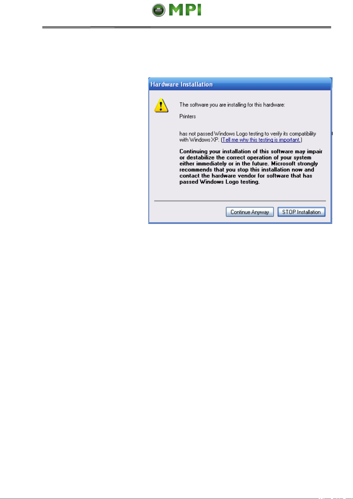
For XP system, the following situation may appear after you click “Finish” in
above step:
1) If the driver is not yet
Microsoft Certified, the
message on the right would
appear. Click “Continue
Anyway”. (As we continue to
expand our product portfolio,
not all of our drivers may be
certified yet. Please check our
website www.dascom.com for
the latest certified drivers.)
2) Installation in progress.
6. After installation is completed
successfully, you will see the
message on the right.
13
Page 29

Tally Dascom 1140
Paper type
Weight (g/m2) / ply
Thickness (mm)
Gap lever position
Single sheet
52~100
0.06~0.12
1P~2P
3-ply
40~52
0.12~0.14
3P~4P
4-ply
40~52
0.17~0.22
4P~5P
5-ply
40~52
0.23~0.27
5P
Change ribbon
---
Above 0.58
RIBBON
Mantenimiento Periféricos Informáticos SL C/Canteras, 15 28860 Paracuellos de Jarama Tel: 00 34 917481604 WEB: https://mpi.com.es
3 Paper Installation Guide
The printer can handle either single sheets or continuous forms. Single sheets, also called
cut sheets, include envelopes and non-continuous, multipart forms. Continuous forms
include labels and multipart forms fed into the printer using the forms tractors. The printer is
able to print 1~5 plies multipart paper.
Remove the paper-clips. Do not load paper that has been folded or damaged,
wrinkled, or curled.
3.1 Adjusting the Print Gap Lever
The print gap lever is on the left side of the printer inside the top cover. Take care to adjust
the print gap lever to a suitable position whenever you change the number of copies being
printed. Using the wrong print gap may cause print head damage or paper jams.
There are 2 paper feed modes: friction feed and tractor feed.
3.2 Friction Feed Handling
1. Raise the single sheet feeder until it locks into its mounting.
2. Move the paper-feed lever forward to “ ” for friction feed mode. Make sure that no
paper is in the printer when you switch the paper path.
3. Adjust the print gap lever if necessary.
4. Align the left paper guide with the mark on the left of the single sheet feeder.
14
Page 30

Tally Dascom 1140
Mantenimiento Periféricos Informáticos SL C/Canteras, 15 28860 Paracuellos de Jarama Tel: 00 34 917481604 WEB: https://mpi.com.es
5. Adjust the right paper guide to the width of the paper used.
6. Insert a sheet of paper. Make sure that the bottom edge of the paper engages snugly
with the platen. Please push the paper in manually if the paper does not feed in while
the friction roller is running.
7. The paper should advance automatically to the print position. The printer is now ready
to print in the online state.
3.3 Tractor Feed Handling
1. Move the paper-feed lever backward to “ ” for continuous paper position.
2. Adjust the print gap lever if necessary.
3. Raise the tractor doors and fit the first 3 paper holes onto the left tractor pins. Close the
left tractor door. In the same way, install the paper on the right tractor.
4. Adjust the right tractor to the width of the paper until the paper is flat. Do not stretch the
paper too taut. Push the right lock lever down to secure the right tractor in place.
5. Press the【Load/Eject】key to load the paper to the starting print position. The printer
is now ready to print in the online state.
15
Page 31

Tally Dascom 1140
Mantenimiento Periféricos Informáticos SL C/Canteras, 15 28860 Paracuellos de Jarama Tel: 00 34 917481604 WEB: https://mpi.com.es
3.4 Continuous Paper Placement
1. Place the printer on a solid base. The minimum suitable height of the solid base is
75 cm.
2. Left and right positioning: The direction of continuous paper should be parallel with the
paper guide. The tolerance should be less than 3 cm.
3. Front and back positioning: The distance between the rear of printer and the wall
should be more than 60cm. To avoid paper jam, the distance between the continuous
paper and the edge of desk should be 10~15 cm.
16
Page 32

Tally Dascom 1140
Mantenimiento Periféricos Informáticos SL C/Canteras, 15 28860 Paracuellos de Jarama Tel: 00 34 917481604 WEB: https://mpi.com.es
4 Control Panel Operation
Note: A black filled circle means LED off; A white circle means LED on.
There are 4 switches S1~S4 and 4 LEDs L1~L4. The meaning and application of each
switch and LED are described below:
4.1 LED Indicators
“Power/Paper Out” LED:
On: Power on
Flashing: Paper out
Flashing + buzzer: Paper jam
“Font 1 and Font 2” LED:
Flashing together: Indicates continuous paper is at tear-off position; otherwise it indicates the
selected font. See table 4.1.
“Online” LED:
On: The printer is in online state and ready to receive data from the computer.
Off: The printer is in offline state and cannot receive data.
17
Page 33

Tally Dascom 1140
Font Selection Label
L2 State
L3 State
Tear Off
Blink
Blink
Draft
Off
Off
Draft Condensed
Off
On
Quadrato
Off
Blink
Quadrato Condensed
On
Off
Courier
On
On
Courier Condensed
On
Blink
OCR B
Blink
Off
OCR A
Blink
On
Switch
Label
S1
Tear off
S2
LF/FF
S3
Load/Eject
S4
Online
Mantenimiento Periféricos Informáticos SL C/Canteras, 15 28860 Paracuellos de Jarama Tel: 00 34 917481604 WEB: https://mpi.com.es
4.2 Control Panel Keys
“Tear Off” Key:
When online, this key will move any loaded continuous paper to the tear-off position. When
in setup state, this key is used to select the desired font.
“LF/FF” Key:
Pressing this key will feed paper one line forward. By holding down this key, the printer will
initially feed a few lines, then perform a form feed (continuous paper mode) or eject the form
(single sheet mode).
“Load/Eject” Key:
When paper is loaded, pressing this key will eject the paper (single sheet mode) or park the
paper (continuous paper mode). When paper is not loaded, pressing this key will load the
paper to the starting print position.
“Online” Key:
This key switches the printer between online and offline states. Printing is stopped when the
printer is switched to offline state. When printer is switched to online state again, printing will
resume.
Table 4.1
Table 4.2
18
Page 34

Tally Dascom 1140
LED
Function
L1
Power/Paper Out
L2
Font1
L3
Font2
L4
Online
Mantenimiento Periféricos Informáticos SL C/Canteras, 15 28860 Paracuellos de Jarama Tel: 00 34 917481604 WEB: https://mpi.com.es
Table 4.3
4.3 Panel Operation
There are 3 states of operation: Online, Setup and Power On.
In the Online state, the keys provide the following functions: Go to Tear Off position, Line
Feed/Form Feed, Load/Eject, Clear Buffer and switch to offline state for accessing to Setup
state.
In the Setup state, the keys provide font selection, and micro feed paper.
To enter the Power On state, the user holds down a key or a combination of keys while
powering up the printer. This state provides the following functions: Hex-dump, Main Menu
setup, print Main Menu, Customize Form, restore factory defaults, and firmware update.
The followings describe the 3 states in details.
Legend:
[A] = press and hold switch A
{B} = press and then release switch B
[A]+ {B} = press switch B while holding A
19
Page 35

Tally Dascom 1140
Function
Name
Switch
Operation
LED
Function Description
Tear Off
{S1}
L2, L3 flash
This is valid for tractor mode only. It feeds the form
to the tear-off position. After tearing off the form,
printing starts on the next TOF by pressing any key
or receiving print data from the host.
LF
{S2}
-
Feeds one line with every press of S2
FF
[S2]
-
Pressing this key will feed paper one line forward.
By holding down this key, the printer will initially feed
a few lines, then perform a form feed (continuous
paper mode) or eject the form (single sheet mode).
Load/Eject
{S3}
-
● Load: Automatically loads the paper (according to
path selection) when no paper is on the platen.
● Eject: For rear tractor, it retracts the form from the
platen to allow users to install cut sheets. (NOTE:
Users have to toggle the path selection lever.) For
cut sheets, it ejects the form on the platen.
Online
{S4}
L4
Toggles between Online and Offline states.
Setup State
[S4]
L4
Hold the S4 key for 3 seconds. Toggles to 3s Setup
state. Indicated by flashing L4.
Clear Buffer
and Reset
[S4]+{S1}
--
● Clears the print buffer. Beeps once upon
completion.
● Pressing S1 longer initializes the printer to
default settings.Beeps 3 times upon completion.
Mantenimiento Periféricos Informáticos SL C/Canteras, 15 28860 Paracuellos de Jarama Tel: 00 34 917481604 WEB: https://mpi.com.es
4.4 Online State
20
Page 36

Tally Dascom 1140
Function
Name
Switch
Operation
LED
Function Description
Online state
{S4}
L4
Toggling to the Online state will cause the printer to
go into a ready-to-print state. Any changes made in
Setup state will be saved permanently. Lighting up
L4 indicates the Online state.
Micro UP
{S3}
--
Press S3 to micro feed paper up.
Micro Down
{S2}
--
Press S2 to micro feed paper down.
Font Select
{S1}
L2, L3
Refer to Table 4.1 for details.
Mantenimiento Periféricos Informáticos SL C/Canteras, 15 28860 Paracuellos de Jarama Tel: 00 34 917481604 WEB: https://mpi.com.es
4.5 Setup State
4.6 Power-On State
21
Page 37

Tally Dascom 1140
Function
Name
Switch
Operation
LED
Function Description
Hex Dump
[S3]
-
Beeps once to indicate going into hex dump mode:
● Prints data from host in hexadecimal
representation.
● Pressing S4 suspends the printing.
● When the hex dump has finished, pressing S4
forces the printing of the last line of data, as any
line termination control code from host has no
function.
● Switch off the power to terminate the hex dump.
Menu Setup
/ EDS
[S1]
-
Allows for Main Menu setting changes. Please read
the instructions printed on how to change settings
when this mode is activated. (EDS: Electronic DIP
Switch)
Self Test /
Status Page
[S4]
-
Prints the printer settings and self-test pattern.
Firmware
Update
[S1]+[S2]+[S3]
+ [S4]
L3, L4
● Alternate flashing of L3 and L4 indicates ready
for firmware update from host.
● When new firmware is being received: L3 and L4
flash together, while L1 and L2 LEDs are
constantly on.
When downloading is completed, the carriage
returns to home position. Printer initializes normally.
Restore
Factory
Defaults
[S2] + [S4]
-
Restore all settings to factory defaults.
The carriage initializes and the printer beeps once
after restoration.
Customize
Form
[S3] + [S4]
To customize the margins and tear-off position,
please refer Chapter 6 for details.
Mantenimiento Periféricos Informáticos SL C/Canteras, 15 28860 Paracuellos de Jarama Tel: 00 34 917481604 WEB: https://mpi.com.es
22
Page 38

Tally Dascom 1140
System setup
Valid Settings
Function
Language
English,Deutsch,
Poccия,
Italiano,Français,Españ
ol, Türkçe, Português
Allows user to select one of the following
languages: English, German, Russian, Italian,
French, Spanish and Turkish, Portuguese
Emulation
ESC/P2, IBM 2380+
Selects the printer emulation. This should be the
same as the host printer driver.
Auto CR
(ESC/P2)
No, Yes
Yes: LF = LF+CR; No: LF = LF
(Applies to ESC/P2 emulation only)
Auto CR(IBM)
No, Yes
Yes: LF = LF+CR; No: LF = LF
(Applies to IBM emulation only)
Auto LF
No, Yes
Yes: CR = CR+LF; No: CR = CR
Print Dir
Bi-Dir, Uni-Dir
Bi-Dir: Graphics and text are printed in both
directions, resulting in faster printing speed.
Uni-Dir: Graphics and text are printed from left to
right, resulting in higher precision.
Zero
0, Ø
0: No-slashed Zero 0.
Ø: Slashed Zero Ø.
Graphic Speed
Normal, Fast
Selects different print quality and print speed for
graphic.
Change Pin#1:
No, 1, 2, 3, 4, 5, 6, 7, 8,
9
Defines the first broken / worn out pin. This pin
will be substituted by an adjacent pin in the
second pass printing.
No: Not to substitution of the worn out pin.
Change Pin #2
No, 1, 2, 3, 4, 5, 6, 7, 8,
9
Defines the first broken / worn out pin. This pin
will be substituted by an adjacent pin in the
second pass printing.
No: No substitution.
Mantenimiento Periféricos Informáticos SL C/Canteras, 15 28860 Paracuellos de Jarama Tel: 00 34 917481604 WEB: https://mpi.com.es
5 Printer Setting Changes
In order to meet specific print requirements, the printer configurations may be changed as
follows: Hold down the Load/Eject key while powering on the printer and then release the
key when the print head starts to move. The printer will enter Main Menu setup state. Follow
the instructions printed on how to make setting changes. When a new setting is saved, it is
retained after the printer has been powered off.
The Printer Settings menu contains 8 sub-menus: System Setup, Paper Setup, Interface
Setup, Character Setup, Other Setup, Bi-directional Alignment, BlackMark Mode,Restore
Facotry Defaults.
5.1 System Setup
23
Page 39

Tally Dascom 1140
System setup
Valid Settings
Function
Power-Saving
OFF, 1min, 2min, 5min,
10min
Defines the idle period before the printer gets
into Save-energy Mode.
OFF: The printer never goes into Save-energy
Mode.
Impact
Normal, Heavy
Normal: The print speed is faster causing head
hot easily and the impact force is weaker.
Heavy: The print speed is reduced, resulting
better thermal performance and copy capability.
Paper Setup
Valid Settings
Function
Single FormLen
2.5, 11/4, 3, 3.5,
11/3, 4, 5, 5.5, 6, 7,
8, 9, 10, 11, 12, 14,
A4, B4, Define
Sets the page length for single paper
Single Top
0, 1/6, 1/4, 1/3, 1/2,
2/3, 3/4, 1, Define
Defines the separation in inches from the top edge
of a single paper to the first print line.
Single Bottom
0, 1/6, 1/4, 1/3, 1/2,
2/3, 3/4, 1, Define
Defines the separation in inches from the bottom
edge of a single paper to the last print line.
Single Left Mrg
(1.00mm)
-7, -6, -5, -4, -3, -2, -
1, 0, 1, 2, 3, 4, 5, 6,
7, Define
Compensation value added to Single Left Mrg.
Single Top
Mrg (0.01”)
-7, -6, -5, -4, -3, -2, -
1, 0,1, 2, 3, 4, 5, 6, 7
Compensation value added to Single Top.
Single Auto Load
Disable, 0.5sec,
1sec, 1.5sec, 2sec
Defines the settling time before a single sheet is
loaded.
Disable: Press the【Load/Eject】key manually to
load a single sheet.
Fanfold FormLen
2.5, 11/4, 3, 3.5,
11/3, 4, 5, 5.5, 6, 7,
8, 9, 10, 11, 12, 14,
A4, B4, Define
Sets the Page Length for fanfold.
Fanfold Top
0, 1/6, 1/4, 1/3, 1/2,
2/3, 3/4, 1, Define
Defines the separation in inches from the top edge
of a fanfold to the first print line.
Fanfold Bottom
0, 1/6, 1/4, 1/3, 1/2,
2/3, 3/4, 1, Define
Define the separation in inches from the bottom
edge of a fanfold to the last print line.
Fanfold Left Mrg
(1.00mm)
-7, -6, -5, -4, -3, -2, -
1, 0, 1, 2, 3, 4, 5, 6,
7, Define
Compensation value added to Fanfold Left Mrg.
Fanfold Top Mrg
(0.01”)
-7, -6, -5, -4, -3, -2, -
1, 0, 1, 2, 3, 4, 5, 6, 7
Compensation value added to Fanfold Top.
Mantenimiento Periféricos Informáticos SL C/Canteras, 15 28860 Paracuellos de Jarama Tel: 00 34 917481604 WEB: https://mpi.com.es
5.2 Paper Setup
24
Page 40

Tally Dascom 1140
Paper Setup
Valid Settings
Function
Skip
No, Yes
Skips printing on perforation area.
Only valid to fanfold.
Yes: Blank lines between 2 pages.
No: No blank lines between 2 pages.
Tear
Auto, Manual,
View, Auto @ FF
Auto: No incoming print data in 1~2 seconds after
printing completed, the printer advances the form
to the tear-off position. When the printer receives
new print data, the form is ejected to the top-ofform.
Manual: After the completion of a print job, press a
panel key to advance the paper to the tear-off
position.
View: No incoming print data in 1~2 seconds after
printing completed causes the printer to advance
the paper by 2 lines. Printing resumes 2 lines
below the torn edge.
Auto @FF: a form feed command is necessary to
auto feed the form to tear position.
Buzzer
No, Yes
No: Buzzer does not sound if out of paper.
Yes: Buzzer sounds if out of paper.
BlackMark
No, Yes
No: Disables black mark sensor.
Yes: Enables black mark sensor.
When “Yes” and online, pressing the Load/Eject
key advances the paper to the tear-off position.
BlackMark commands: (also see section 5.6)
1D 0C:
Feeds paper to the print position designated by
the black mark. Advance the paper to the tear-off
position after printing.
1C 28 4C 03 00 42 m:
m = 0: feeds paper to the print position
designated by the black mark.
m = 1: feeds paper to the black mark tear-off
position.
Mantenimiento Periféricos Informáticos SL C/Canteras, 15 28860 Paracuellos de Jarama Tel: 00 34 917481604 WEB: https://mpi.com.es
25
Page 41

Tally Dascom 1140
Paper Setup
Valid Settings
Function
Bail mode
Invalid,Standard,
Special
The pressure lever presses the paper against the
print platen during printing, but it is released for
paper loading.
Invalid: If you uninstall the lever or want to disable
the function, set this setting to “invalid”.
Standard: Release the lever for paper loading and
lower the lever to press the paper against the
platen during printing.
Special: When the paper is in tear-off position, after
the printer received printing data, the printer will
judge whether tear-off was implemented first. If
tear-off was implemented and printing position is in
lever area, then the printer will press the lever; If
tear-off was not implemented, the printer will not
press the lever.
Roll Paper
No, Yes
In friction mode, 【LF/FF】will not eject the paper
and feed to next page. (Assume roll paper)
Interface setup
Valid Settings
Function
PnP
No, Yes
No: Disables plug and play for USB
Yes: Enables plug and play.
USB ID
No, Yes
No: Disables USB ID.
Yes: Enables USB ID
Mantenimiento Periféricos Informáticos SL C/Canteras, 15 28860 Paracuellos de Jarama Tel: 00 34 917481604 WEB: https://mpi.com.es
5.3 Interface Setup
26
Page 42

Tally Dascom 1140
Character setup
Valid Settings
Function
Character Table
Italic, Graphic
Italic: Selects standard character sets.
Please refer to UG for details.
Graphic: Selects IBM character sets.
Please refer to UG for details.
Character Group
Group 1, Group 2
The interpretation of ASCII codes
between 0x80~0x9F:
Group 1: as control codes.
Group 1: as printable characters.
Int'l Char Set
USA, France, Germany, UK,
DenmarkI, Sweden, Italy, SpainI,
Japan, Norway, DenmarkII, Spain
II, LatinAm, Denmark, China
International character set selections
Font
Draft,DraftCond,Quadrato,Quadr
atoCond,Courier,CourierCond,
OCR B,OCR A
Selects the font.
Pitch(cpi)
10, 12, 15, 17, 20, PS
Controls the characters per inch
setting.
Code Page
CP 437, CP 737, CP 850, CP
851, CP 852, CP 857, CP 858,
CP 860, CP 861, CP 863, CP
1252, CP 1253, CP 1254, 88591, 8859-1 (SAP), 8859-2, 8859-5,
8859-7, 8859-9, 8859-15,
Kamenicky , Mazovia, 866
Bulgaria, CP 1250, CP 1251.
BRASCII, Abicomp, CP 865, CP
866, CRO-ASCII
Code page selections
HS-Draft
No, Yes
Yes: Prints High Speed Draft when
Draft font is selected.
Mantenimiento Periféricos Informáticos SL C/Canteras, 15 28860 Paracuellos de Jarama Tel: 00 34 917481604 WEB: https://mpi.com.es
5.4 Character Setup
27
Page 43
Tally Dascom 1140
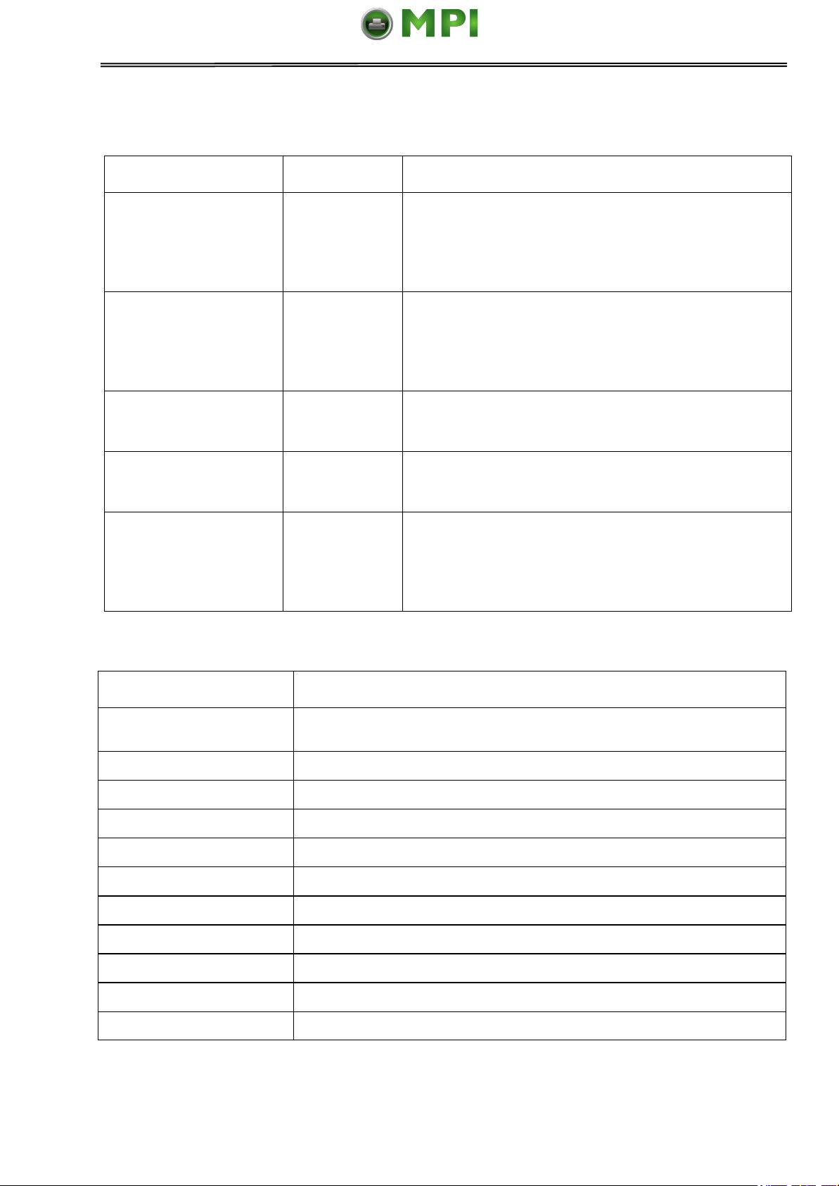
Other setup
Valid Settings
Function
Form Length Ctrl
No, Yes
No: Form length commands are invalid in neither
of the emulation.
Yes: Form length commands are valid in either of
the emulations.
Print Speed Ctrl
No, Yes
No: Print speed commands are invalid in neither of
the emulation.
Yes: Print speed commands are valid in either of
the emulations.
Pitch Ctrl
No, Yes
No: Ignores CPI commands
Yes: CPI commands are valid
Font Ctrl
No, Yes
No: Ignores font select commands
Yes: font select commands are valid
Uni-Dir Ctrl
No, Yes
No: Uni-Direction print commands are invalid in
neither of the emulation.
Yes: Uni-Direction print commands are valid in
either of the emulations.
System Setup
Gültige Werte
Sprache
English, Deutsch, Poccия, Italiano, Français, Español, Türkçe,
Português
Emulation
ESC/P2, IBM 2380+
Auto CR (ESC/P2)
Nein, Ja
Auto CR (IBM)
Nein, Ja
Auto LF
Nein, Ja
Druck Dir
Bi-Dir, Uni-Dir
Null
0, Ø
Graphikgeschw.
Normal, Schnell
Ersetze 1.Nadel
No, 1, 2, 3, 4, 5, 6, 7, 8, 9
Ersetze 2.Nadel
No, 1, 2, 3, 4, 5, 6, 7, 8, 9
Impact Mode
Normal, Stark
Mantenimiento Periféricos Informáticos SL C/Canteras, 15 28860 Paracuellos de Jarama Tel: 00 34 917481604 WEB: https://mpi.com.es
5.5 Other Setup
5.5.1 German (Deutsch)
28
Page 44

Tally Dascom 1140
Papier Setup
Gültige Werte
Einzel Länge
2.5, 11/4, 3, 3.5, 11/3, 4, 5, 5.5, 6, 7, 8, 9, 10, 11, 12, 14, A4, B4,
Definiert
Einzel Ob Rand
0, 1/6, 1/4, 1/3, 1/2, 2/3, 3/4, 1, Definiert
Einzel Unt Rand
0, 1/6, 1/4, 1/3, 1/2, 2/3, 3/4, 1, Definiert
Einzel Li Rand
-7, -6, -5, -4, -3, -2, -1, 0, 1, 2, 3, 4, 5, 6, 7, Definiert
Einzel Ob Rand Fein
-7, -6, -5, -4, -3, -2, -1, 0, 1, 2, 3, 4, 5, 6, 7
Auto Laden
Ungültig, 0.5sec, 1sec, 1.5sec, 2sec
Endlos Form Länge
2.5, 11/4, 3, 3.5, 11/3, 4, 5, 5.5, 6, 7, 8, 9, 10, 11, 12, 14, A4, B4,
Definiert
Endlos Ob Rand
0, 1/6, 1/4, 1/3, 1/2, 2/3, 3/4, 1, Definiert
Endlos Unt Rand
0, 1/6, 1/4, 1/3, 1/2, 2/3, 3/4, 1, Definiert
Endlos Li Rand
-7, -6, -5, -4, -3, -2, -1, 0, 1, 2, 3, 4, 5, 6, 7, Definiert
Endlos Ob Rand Fein
-7, -6, -5, -4, -3, -2, -1, 0, 1, 2, 3, 4, 5, 6, 7
Perforationssprung
Nein, Ja
Abreissen
Auto, Manuell, Kurz, Auto@FF
Summer
Nein, Ja
Black Mark
Nein, Ja
Andruckbügelmodus
Ungültig, Standard, Spezial
Schnittstellen Setup
Gültige Werte
PnP
Nein, Ja
USB ID
Nein, Ja
Zeichen Setup
Gültige Werte
Zeichentabelle
Italic, Graphik
PC-Zeichensatz
Gruppe 1, Gruppe 2
Land
USA, Frankreich, Deutschland, UK, Dänemark I, Schweden,
Italien, Spanien I, Japan, Norway, Dänemark II, Spanien II, LatAmerika, Dänemark/Norwegen, China
Font
Draft, DraftCond, Quadrato, QuadratoCond, Courier,
CourierCond, OCR B, OCR A
Laufweite(cpi)
10, 12, 15, 17, 20, PS
Zeichensatz
CP 437, CP 737…
HS-Draft
Nein, Ja
Formularlänge Strg
Nein, Ja
Geschwindigkeit Strg
Nein, Ja
Laufweite Strg
Nein, Ja
Font Strg
Nein, Ja
Uni-dir Strg
Nein, Ja
Mantenimiento Periféricos Informáticos SL C/Canteras, 15 28860 Paracuellos de Jarama Tel: 00 34 917481604 WEB: https://mpi.com.es
29
Page 45
Tally Dascom 1140
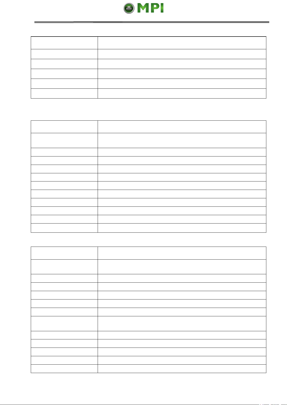
Erweitertes Setup
Gültige Werte
Formularlänge Strg
Nein, Ja
Geschwindigkeit Strg
Nein, Ja
Laufweite Strg
Nein, Ja
Font Strg
Nein, Ja
Uni-dir Strg
Nein, Ja
обновление системы
Правильные значения
Яэык
English, Deutsch, Poccия, Italiano, Français, Español, Türkçe,
Português
Эмуляция
ESC/P2, IBM 2380+
Авто CR( ESC/P2)
НET, Да,
Авто CR (IBM)
НET, Да,
Авто LF
Нem, Да
направлениe пeчaти
Однонаправ, Двунаправ
Ноль
0, Ø
Скнпнсть oечатк
Hopмaльнo, быстро
Заменa 1.иглы
No, 1, 2, 3, 4, 5, 6, 7, 8, 9
Заменa 2 иглы
No, 1, 2, 3, 4, 5, 6, 7, 8, 9
воздействия
Нормaльно, сильно
Настройка бумаги
Правильные значения
Длина отдельн. листов
2.5, 11/4, 3, 3.5, 11/3, 4, 5, 5.5, 6, 7, 8, 9, 10, 11, 12, 14, A4, B4,
определен
Верх. поле oтд. лист
0, 1/6, 1/4, 1/3, 1/2, 2/3, 3/4, 1, определен
нижн. поле отд. лист
0, 1/6, 1/4, 1/3, 1/2, 2/3, 3/4, 1, определен
Слевa отстyл лист
-7, -6, -5, -4, -3, -2, -1, 0, 1, 2, 3, 4, 5, 6, 7, определен
Верх отс. л. тонко
-7, -6, -5, -4, -3, -2, -1, 0, 1, 2, 3, 4, 5, 6, 7
Автозагрузка
недейств, 0.5sec, 1sec, 1.5sec, 2sec
Длина непрер. бумаги
2.5, 11/4, 3, 3.5, 11/3, 4, 5, 5.5, 6, 7, 8, 9, 10, 11, 12, 14, A4, B4,
определен
Верх. поле непр. бум
0, 1/6, 1/4, 1/3, 1/2, 2/3, 3/4, 1, определен
нижн. поле непр бум
0, 1/6, 1/4, 1/3, 1/2, 2/3, 3/4, 1, определен
Слевa отстyл нeпpep
-7, -6, -5, -4, -3, -2, -1, 0, 1, 2, 3, 4, 5, 6, 7, определен
Верх отс. тонко нeпp
-7, -6, -5, -4, -3, -2, -1, 0, 1, 2, 3, 4, 5, 6, 7
Пропуск перфорации
Нет, Да
Mantenimiento Periféricos Informáticos SL C/Canteras, 15 28860 Paracuellos de Jarama Tel: 00 34 917481604 WEB: https://mpi.com.es
5.5.2 Russian (Россия)
30
Page 46

Tally Dascom 1140
Настройка бумаги
Правильные значения
Отрыв бумаги
Авто, ручной, короткий, Auto@FF
Звук
НET, Да
черной метки
Нет, Да
Мод. прижимн. скоба
Недопустимо, Cтандарт, Специально
Настройка интерфейс
Правильные значения
PnP
НET, Да
USB ID
Нет, Да
Настройка символов
Правильные значения
Таблица знаков
Курсив, Графика
Группа символов
Группа I, группа II
Набор знаков
USA, France, Germany, UK, Дания-I, Sweden, Italy, Spain-I,
Japan, Норвегия, Дания II, Spain II, Латинская Америка,
Дания/Норвегия, Китай
шрифт
Draft, DraftCond, Quadrato, QuadratoCond, Courier,
CourierCond, OCR B, OCR A
знаков/дюйм (cpi)
10, 12, 15, 17, 20, PS
Кодовая таблица
CP437, CP737…
Высокaя скорость
НET, Да
Другие настройки
Правильные значения
длинa формyляp Ctrl
НET, Да
скорости Ctrl
НET, Да
Шaг Ctrl
НET, Да
ШpиФт Ctrl
НET, Да
однонаправленной Ctrl
Нет, Да
Mantenimiento Periféricos Informáticos SL C/Canteras, 15 28860 Paracuellos de Jarama Tel: 00 34 917481604 WEB: https://mpi.com.es
31
Page 47
Tally Dascom 1140
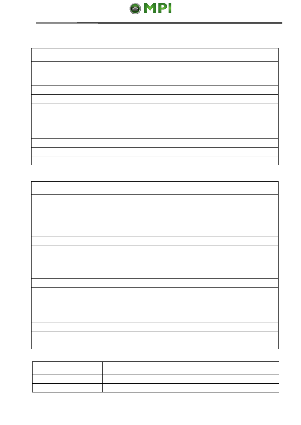
Setup sistema
Impostazioni Valide
Linguaggio
English, Deutsch, Poccия, Italiano, Français, Español, Türkçe,
Português
Emulazione
ESC/P2, IBM 2380+
Auto CR (ESC/P2)
No, Si
Auto CR (IBM)
No, Si
Auto LF
No, Si
Direz. Stampa
Bi-Dir, Uni-Dir
Zero
0, Ø
Veloc. Grafica
Normale, Veloce
Primo ago rotto
No, 1, 2, 3, 4, 5, 6, 7, 8, 9
Secondo ago rotto
No, 1, 2, 3, 4, 5, 6, 7, 8, 9
Modo Impatto
Normale, Pesante
Imposta carta
Impostazioni Valide
Lunghezza Foglio
2.5, 11/4, 3, 3.5, 11/3, 4, 5, 5.5, 6, 7, 8, 9, 10, 11, 12, 14, A4, B4,
Definito
Margine Sup. Foglio
0, 1/6, 1/4, 1/3, 1/2, 2/3, 3/4, 1, Definito
Margine Infer. Foglio
0, 1/6, 1/4, 1/3, 1/2, 2/3, 3/4, 1, Definito
Regola foglio a SX
-7, -6, -5, -4, -3, -2, -1, 0, 1, 2, 3, 4, 5, 6, 7, Definito
Regola Sup. Foglio
-7, -6, -5, -4, -3, -2, -1, 0, 1, 2, 3, 4, 5, 6, 7
Autocaricamento
Non valid, 0.5sec, 1sec, 1.5sec, 2sec
Lungh. Mod. Continuo
2.5, 11/4, 3, 3.5, 11/3, 4, 5, 5.5, 6, 7, 8, 9, 10, 11, 12, 14, A4, B4,
Definito
Margine Superiore
0, 1/6, 1/4, 1/3, 1/2, 2/3, 3/4, 1, Definito
Mar. Inf. Continuo
0, 1/6, 1/4, 1/3, 1/2, 2/3, 3/4, 1, Definito
Regola a SX continuo
-7, -6, -5, -4, -3, -2, -1, 0, 1, 2, 3, 4, 5, 6, 7, Definito
Regola Sup. continuo
-7, -6, -5, -4, -3, -2, -1, 0, 1, 2, 3, 4, 5, 6, 7
Salto Perforazione
No, Si
Strappo
Auto STP, STP manuale, STP corto, Auto@FF
Cicalino
No, Si
Segno nero riferim
No, Si
Barra rullini
Non valido, Standard, Speciale
Setup IF
Impostazioni Valide
PnP
No, Si
ID USB
No, Si
Mantenimiento Periféricos Informáticos SL C/Canteras, 15 28860 Paracuellos de Jarama Tel: 00 34 917481604 WEB: https://mpi.com.es
5.5.3 Italian (Italiano)
32
Page 48
Tally Dascom 1140
Imposta caratteri
Impostazioni Valide
Tabella Caratteri
Italico, Grafica
Gruppo Carattere
Groupo 1, Groupo 2
Set Carat. Int.
USA, Francia, Germania, Regno Unito, Danimarca I, Svezia,
Italia, Spagna I, Giappone, Norvegia, Danimarca II, Spagna II,
Sudamerica, Danimarca/Norvegia, Porcellana
Fonte
Draft, DraftCond, Quadrato, QuadratoCond, Courier,
CourierCond, OCR B, OCR A
Spaziatura (cpi)
10, 12, 15,17, 20,PS
Code Page
CP437, CP737…
HS-Bozza
No, Si
Altri Setup
Impostazioni Valide
Comando lunghezza
No, Si
Comando velocità
No, Si
Comando Spaziatura
No, Si
Comando Fonte
No, Si
Comando stampa mono
No, Si
Réglage Système
Paramètres Valides
Language
English, Deutsch, Poccия, Italiano, Français, Español, Türkçe,
Português
Emulation
ESC/P2, IBM 2380+
RC-Auto (ESC/P2)
Non, Oui
RC-Auto (IBM)
Non, Oui
SL-Auto
Non, Oui
Dir Impr
Bidir, Unidir
Zéro
0, Ø
Vitesse graphiq.
Normal, Rapide
Changer aiguille 1
Non, 1, 2, 3, 4, 5, 6, 7, 8, 9
Changer aiguille 2
Non, 1, 2, 3, 4, 5, 6, 7, 8, 9
Mode Impact
Normal, Fort
Mantenimiento Periféricos Informáticos SL C/Canteras, 15 28860 Paracuellos de Jarama Tel: 00 34 917481604 WEB: https://mpi.com.es
5.5.4 French (Français)
33
Page 49
Tally Dascom 1140
Réglage papier
Paramètres Valides
Feuille LongPage
2.5, 11/4, 3, 3.5, 11/3, 4, 5, 5.5, 6, 7, 8, 9, 10, 11, 12, 14, A4, B4,
Définie
Bord Sup. Feuille
0, 1/6, 1/4, 1/3, 1/2, 2/3, 3/4, 1, Définie
Bord Inf. Feuille
0, 1/6, 1/4, 1/3, 1/2, 2/3, 3/4, 1, Définie
Marge Gauche Feuille
-7, -6, -5, -4, -3, -2, -1, 0, 1, 2, 3, 4, 5, 6, 7, Définie
Marge Haute Feuille
-7, -6, -5, -4, -3, -2, -1, 0, 1, 2, 3, 4, 5, 6, 7
Chargem. Autom
Non, 0.5sec, 1sec, 1.5sec, 2sec
Listing Longpage
2.5, 11/4, 3, 3.5, 11/3, 4, 5, 5.5, 6, 7, 8, 9, 10, 11, 12, 14, A4, B4,
Définie
Listing Bord Sup.
0, 1/6, 1/4, 1/3, 1/2, 2/3, 3/4, 1, Définie
Listing Bord infér
0, 1/6, 1/4, 1/3, 1/2, 2/3, 3/4, 1, Définie
Listing Marge Gauche
-7, -6, -5, -4, -3, -2, -1, 0, 1, 2, 3, 4, 5, 6, 7, Définie
Listing Marge Haute
-7, -6, -5, -4, -3, -2, -1, 0, 1, 2, 3, 4, 5, 6, 7
Saut perforation
Non, Oui,
Coupe
Auto, Manuelle, Courte, Auto@FF
Alarma
Non, Oui
Mode Repère Noir
Non, Oui
Mode entrainement
Non Valid, Standard, Spécial
Config Interface
Paramètres Valides
PnP
Non, Oui
USB ID
Non, Oui
Config. Caractère
Paramètres Valides
Table caractere
Italique, Graphique
Groupe Caractères
Groupe 1, Groupe 2
Pays
USA, France, Allemagne, Royaume-Uni, Denmark I, Suède,
Italie, Espagne, Japon, Norvège, Denmark II, Espagne II,
Ameriquelat, Denmark/Norvège, Chine
Police
Draft, DraftCond, Quadrato, QuadratoCond, Courier,
CourierCond, OCR B, OCR A
Espacement (cpi)
10, 12, 15, 17, 20, PS
Code Page
CP437, CP737…
HS-Draft
Non, Oui
Mantenimiento Periféricos Informáticos SL C/Canteras, 15 28860 Paracuellos de Jarama Tel: 00 34 917481604 WEB: https://mpi.com.es
34
Page 50

Tally Dascom 1140
Autre réglage
Paramètres Valides
Ctrl LongPage
Non, Oui
Ctrl Vitesse Impr.
Non, Oui
Ctrl Espacement
Non, Oui
Ctrl Fonte
Non, Oui
Ctrl Impr. Uni-Dir
Non, Oui
Config. Sistema
Ajustes validos
Lenguage
English, Deutsch, Poccия, Italiano, Français, Español, Türkçe,
Português
Emulación
ESC/P2, IBM 2380+
Auto CR (ESC/P2)
No, Si
Auto CR (IBM)
No, Si
Auto LF
No, Si
ModoImpresión
Bi-Dir, Uni-Dir
Cero con barra
0, Ø
Imp. Grafica
Normal, Rápido
Sust. 1er pin roto
Non, 1, 2, 3, 4, 5, 6, 7, 8, 9
Sust. 2do pin roto
Non, 1, 2, 3, 4, 5, 6, 7, 8, 9
Modo de Impacto
Normal, Fuerte
Config. Papel
Ajustes validos
Tam. Hojas Sueltas
2.5, 11/4, 3, 3.5, 11/3, 4, 5, 5.5, 6, 7, 8, 9, 10, 11, 12, 14, A4, B4,
Definido
Margen Sup. Hoja S.
0, 1/6, 1/4, 1/3, 1/2, 2/3, 3/4, 1, Definido
Margen Inf. Hoja S
0, 1/6, 1/4, 1/3, 1/2, 2/3, 3/4, 1, Definido
Marg. Izq. Hoja S.
-7, -6, -5, -4, -3, -2, -1, 0, 1, 2, 3, 4, 5, 6, 7, Definido
Marg. Sup. Hoja S.
-7, -6, -5, -4, -3, -2, -1, 0, 1, 2, 3, 4, 5, 6, 7
Auto Carga
Inválido, 0.5sec, 1sec, 1.5sec, 2sec
Tam. Papel Continuo
2.5, 11/4, 3, 3.5, 11/3, 4, 5, 5.5, 6, 7, 8, 9, 10, 11, 12, 14, A4, B4,
Definido
Mar. Sup. Pap. Con
0, 1/6, 1/4, 1/3, 1/2, 2/3, 3/4, 1, Definido
Mar. Inf. Pap. Cont.
0, 1/6, 1/4, 1/3, 1/2, 2/3, 3/4, 1, Definido
Marg. Iz. Pap. Cont.
-7, -6, -5, -4, -3, -2, -1, 0, 1, 2, 3, 4, 5, 6, 7, Definido
Marg. Sup. Pap. Cont.
-7, -6, -5, -4, -3, -2, -1, 0, 1, 2, 3, 4, 5, 6, 7
Salto perforación
No, Si
Corte
Automático, Manual, Corto, Auto@FF
Alarma
No, Si
Mantenimiento Periféricos Informáticos SL C/Canteras, 15 28860 Paracuellos de Jarama Tel: 00 34 917481604 WEB: https://mpi.com.es
5.5.5 Spanish (Español)
35
Page 51

Tally Dascom 1140
Config. Papel
Ajustes validos
Modo Marca Negra
No, Si
Modo de barra de
presión
Inválido, Estándar, Especial
Conf. Interface
Ajustes validos
PnP
No, Si
ID USB
No, Si
Config. Carácter
Ajustes validos
Tabla de Caracteres
Italic, Grafica
Grupo de Caracteres
Grupo 1, Grupo 2
Juego Carácter Int.
USA, Francia, Alemania, Reino Unido, Dinamarca I, Suecia,
Italia, España, Japón, Noruega, Dinamarca II, España II,
AméricaLat, Dinamarca, China
Tamaño Letra (cpi)
10, 12, 15, 17, 20, PS
Fuente
Draft, DraftCond, Quadrato, QuadratoCond, Courier,
CourierCond, OCR B, OCR A
Tabla Carácter
CP437, CP737…
Alta Velocidad
No, Si
Config. Otros
Ajustes validos
Cmd. Long. de Hoja
No, Si
Cmd. Vel. Impresión
No, Si
Cmd. Tamaño Letra
No, Si
Cmd. Fuente
No, Si
Cmd. Imp. Uni-dir
No, Si
Mantenimiento Periféricos Informáticos SL C/Canteras, 15 28860 Paracuellos de Jarama Tel: 00 34 917481604 WEB: https://mpi.com.es
36
Page 52
Tally Dascom 1140
Sistem Ayarı
Geçerli ölçüler
Lisan
English, Deutsch, Poccия, Italiano, Français, Español,
Türkçe, Português
Emülation
ESC/P2, IBM 2380+
Otom. Satırbaşı
(ESC/P2)
Hayır, Evet
Otom. Satırbaşı (IBM)
Hayır, Evet
Otom. Satır besleme
Hayır, Evet
Yazdırma yön ü
Ÿki-Yöne Tek-Yöne
Sıfır Sayısı
0, Ø
Grafik Hızı
Normal, Hızı
Arızalı 1. iğne yed
Hayır, 1, 2, 3, 4, 5, 6, 7, 8, 9
Arızalı 2. iğne yed
Hayır, 1, 2, 3, 4, 5, 6, 7, 8, 9
Vuruş modu
Normal, Güçlü
Kağıt Ayarı
Geçerli ölçüler
Tek kağıt uzunluğu
2.5, 11/4, 3, 3.5, 11/3, 4, 5, 5.5, 6, 7, 8, 9, 10, 11, 12, 14, A4, B4,
Oto.Tanım.
Tek-kağıt Üst boşluğu
0, 1/6, 1/4, 1/3, 1/2, 2/3, 3/4, 1, Oto.Tanım.
Tek-kağıt Altkenar
0, 1/6, 1/4, 1/3, 1/2, 2/3, 3/4, 1, Oto.Tanım.
Tek-kağıt Sol ayar
-7, -6, -5, -4, -3, -2, -1, 0, 1, 2, 3, 4, 5, 6, 7, Oto.Tanım.
Tek-kağıt Üst ayar
-7, -6, -5, -4, -3, -2, -1, 0, 1, 2, 3, 4, 5, 6, 7
Otom. Yükleme
Geçersiz, 0.5sec, 1sec, 1.5sec, 2sec
Sürekli Kağıt Uzunluğu
2.5, 11/4, 3, 3.5, 11/3, 4, 5, 5.5, 6, 7, 8, 9, 10, 11, 12, 14, A4, B4,
Oto.Tanım.
Sürekli Üst Marj
0, 1/6, 1/4, 1/3, 1/2, 2/3, 3/4, 1, Oto.Tanım.
Sür. Form Kğt Alt
0, 1/6, 1/4, 1/3, 1/2, 2/3, 3/4, 1, Oto.Tanım.
Sür Form Kğt Sol
-7, -6, -5, -4, -3, -2, -1, 0, 1, 2, 3, 4, 5, 6, 7, Oto.Tanım.
Sür Form Kğt Üst
-7, -6, -5, -4, -3, -2, -1, 0, 1, 2, 3, 4, 5, 6, 7
Delik atlama
Hayır, Evet
Kağıt Kesme
Oto.kesim, Elle kesim, kisa kesim, Auto@FF
ikaz
Hayır, Evet
Siyah Çizgi algı
Hayır, Evet
basınç yay modu
Geçersiz, Standart, özel
Bağlantı Ayarı
Geçerli ölçüler
PnP
Hayır, Evet
USB ID
Hayır, Evet
Mantenimiento Periféricos Informáticos SL C/Canteras, 15 28860 Paracuellos de Jarama Tel: 00 34 917481604 WEB: https://mpi.com.es
5.5.6 Turkish (Türkce)
37
Page 53
Tally Dascom 1140
Karakter ayarı
Geçerli ölçüler
Karakter tablosu
ÿtalik , Grafik
Karakter Grubu
Grup 1, Grup 2
Karakter setleri
Amerika, Fransa, Almanya, İngiltere, Danimarka I, İsveç, İtalya,
İspanya, Japonya, Norveç, Danimarka II, İspanya II, Ltn
Amerika, Danimarka, Çin
Yazı Karakteri
Draft, DraftCond, Quadrato, QuadratoCond, Courier,
CourierCond, OCR B, OCR A
Karakter Sıklığı (cpi)
10, 12, 15, 17, 20, PS
Kod Sayfası
CP437, CP737.
Yük.Hız-Taslak
Hayır, Evet
Diğer Ayarlar
Geçerli ölçüler
Kğt Uzunluk Komutu
Hayır, Evet
Baskı Hızı Komutu
Hayır, Evet
Karak. Aralık Kont.
Hayır, Evet
YazıTipi Komutu
Hayır, Evet
Tek yön bask Komutu
Hayır, Evet
Config. Sistema
Valores válidos
Linguagem
English, Deutsch, Poccия, Italiano, Français, Español,
Türkçe, Português
Emulação
ESC/P2, IBM 2380+
Auto CR (ESC/P2)
Não, Sim
Auto CR (IBM)
Não, Sim
Auto LF
Não, Sim
Direção Imp.
Bi-Dir, Uni-Dir
Zero
0, Ø
Imp. Grafica
Normal, Rápido
Substituiço Pino 1
No, 1, 2, 3, 4, 5, 6, 7, 8, 9
Substituiço Pino 2
No, 1, 2, 3, 4, 5, 6, 7, 8, 9
Modo de Impacto
Normal, Forte
Mantenimiento Periféricos Informáticos SL C/Canteras, 15 28860 Paracuellos de Jarama Tel: 00 34 917481604 WEB: https://mpi.com.es
5.5.7 Portuguese (Português)
38
Page 54
Tally Dascom 1140
Config. Papel
Valores válidos
Tam. Folha Solta
2.5, 11/4, 3, 3.5, 11/3, 4, 5, 5.5, 6, 7, 8, 9, 10, 11, 12, 14, A4, B4,
Definido
Margem Topo Folha
0, 1/6, 1/4, 1/3, 1/2, 2/3, 3/4, 1, Definido
Margem Inf. Folha
0, 1/6, 1/4, 1/3, 1/2, 2/3, 3/4, 1, Definido
Margem Esq. Folha
-7, -6, -5, -4, -3, -2, -1, 0, 1, 2, 3, 4, 5, 6, 7, Definido
Margem Dir. Folha
-7, -6, -5, -4, -3, -2, -1, 0, 1, 2, 3, 4, 5, 6, 7
Carreg. Auto
Desativo, 0.5sec, 1sec, 1.5sec, 2sec
Tam. Form. Cont.
2.5, 11/4, 3, 3.5, 11/3, 4, 5, 5.5, 6, 7, 8, 9, 10, 11, 12, 14, A4, B4,
Definido
Mar. Topo Form. Cont.
0, 1/6, 1/4, 1/3, 1/2, 2/3, 3/4, 1, Definido
Mar. Inf. Form. Cont.
0, 1/6, 1/4, 1/3, 1/2, 2/3, 3/4, 1, Definido
Mar. Esq. Form. Cont.
-7, -6, -5, -4, -3, -2, -1, 0, 1, 2, 3, 4, 5, 6, 7, Definido
Marg. Topo Form. Cont.
-7, -6, -5, -4, -3, -2, -1, 0, 1, 2, 3, 4, 5, 6, 7
Salte perfuração
Não, Sim
Corte
Automático, Manual, Curto, Auto@FF
Cigarra
Não, Sim
Modo Marca Preta
Não, Sim
Modo De Pressão
Invalido, Norma, Especial
Confi. Interface
Valores válidos
PnP
Não, Sim
ID USB
Não, Sim
Config. Caráter
Valores válidos
Tabela de carateres
Italic, Graphic
Grupo de carateres
Group 1, Group 2
Conj. carateres Int.
EUA, França, Alemanha, Reino Unido, Dinamarca, Suécia,
Itália, Espanha, Japão, Noruega, Dinamarca II, Espanha II,
América Lat, Dinamarca, China
Fonte
Draft, DraftCond, Quadrato, QuadratoCond, Courier,
CourierCond, OCR B, OCR A
Passo (cpi)
10, 12, 15, 17, 20, PS
Página de Código
CP437, CP737
Alta Velocidad
Não, Sim
Mantenimiento Periféricos Informáticos SL C/Canteras, 15 28860 Paracuellos de Jarama Tel: 00 34 917481604 WEB: https://mpi.com.es
39
Page 55

Tally Dascom 1140
Config. Outros
Valores válidos
Cmd. Tam. de Folha
Não, Sim
Cmd. Vel. Impresso
Não, Sim
Cmd. Passo
Não, Sim
Cmd. Fonte
Não, Sim
Cmd. Imp. Uni-dir
Não, Sim
Mantenimiento Periféricos Informáticos SL C/Canteras, 15 28860 Paracuellos de Jarama Tel: 00 34 917481604 WEB: https://mpi.com.es
40
Page 56

Tally Dascom 1140
Mantenimiento Periféricos Informáticos SL C/Canteras, 15 28860 Paracuellos de Jarama Tel: 00 34 917481604 WEB: https://mpi.com.es
5.6 Black Mark Parameters
This printer uses tractors to load fanfold forms with pre-printed black marks.
The printer requires 3 parameters to print on paper with black marks:
1. Horizontal offset of black mark from the edge of page (called Black Mark Physical
Horizontal Position); later on, this value facilitates the printer to locate its scanner
preparing for identifying the black marks.
2. Vertical offset of the first print line from the black mark (called Distance Offset From
BlackMark To Print Position); later on, the print makes use of this value to print the first
line relative to the black mark.
3. Vertical offset of the tear-off edge from the black mark (called Distance Offset From
BlackMark To Tear Position); this value informs the printer the tear-off position of the
page.
Not to skip or change the order of setting the above 3 parameters.
The procedures to set the parameters:
1. Hold down the Tear key while powering on the printer and then release the key when
the print head starts to move. After loading paper, the printer prompts the Printer
Settings
Printer Settings
[TEAR]=Back, [LF]=Next, [LOAD/EJECT]=OK, [ONLINE]=Exit,
[ONLINE]+[LOAD/EJECT]=Save and restart the printer.
System Setup
2. Press the Next or Back keys to scroll forward or backward the sub-menus till the
printer shows:
BlackMark Mode
3. Press OK to go into the BlackMark menu. The printer prompts:
[Black Mark Adjustment Mode]
[TEAR]= Back, [LF]= Next, [LOAD/EJECT]=OK, [ONLINE]=Exit,
[ONLINE]+[LOAD/EJECT]= Save and restart the printer.
Black Mark Physical Horizontal Position
Press any key to eject the paper, and load paper with black mark in the Fanfold
Path.
4. The last prompt above advises you to press any key to unload the dialog form. Then
load a fanfold form with black mark.
41
Page 57

Tally Dascom 1140
Mantenimiento Periféricos Informáticos SL C/Canteras, 15 28860 Paracuellos de Jarama Tel: 00 34 917481604 WEB: https://mpi.com.es
5. Ensure to place the lever at position. Then press the Load/Eject key to load the
black marked form. The top edge of the form will then align with the printer’s tear-off
blade. Press Next or Back until you see the black mark marginally exposed out of the
tear-off blade. Then press OK to allow the printer to scan the horizontal offset of the
black mark relative to the left edge of the page. (Meanwhile, the vertical position of the
black mark is measured and recorded.)
When the printer fails to scan the horizontal offset (see the below picture), it prompts
you to repeat the above procedures. If scanning is successful, it prompts:
Successfully setup black mark parameters.
Distance Offset From Black Mark To Print Position
6. The last prompt above invites you to set the next parameter --- vertical offset of the first
print line from the black mark. Like other setting dialogs, you have options:
1) to bypass this setting (by pressing Next or Back), (WARNING: Not to skip or change
the order in Black Mark Setting.)
2) to accept the Distance Offset (by pressing OK),
3) to leave the subsequent settings (by press Exit),
4) to terminate the session and save modified parameter(s) (by pressing Save and
Restart).
7. When you respond with “OK” to set the vertical offset, the printer prompts you to reload
a black marked fanfold form:
Press any key to eject the paper, and load paper with black mark in the Fanfold
Path.
The top edge of the form will then align with the printer’s tear-off blade. Press Next or
Back to feed or reverse-feed the paper till the desired first print line position is reached.
(With the above measured vertical position, the printer will convert the next paper
feeding to the TOF relative to the black mark.) Press OK to confirm the vertical offset.
Then the print prompts the invitation for setting the tear-off position relative to the black
mark:
Successfully setup black mark parameters.
Distance Offset From Black Mark To Tear Position
42
Page 58

Tally Dascom 1140
Mantenimiento Periféricos Informáticos SL C/Canteras, 15 28860 Paracuellos de Jarama Tel: 00 34 917481604 WEB: https://mpi.com.es
8. When you respond with OK to set the tear-off position, the printer prompts you to reload
a black marked fanfold form:
Press any key to eject the paper, and load paper with black mark in the Fanfold
Path.
The printer reloads the form. By default the form stops 5.5 inches away from the
printer’s tear-off blade. Press Next or Back to feed or reverse-feed the paper till the
desired tear-off position is reached. (With the above measured vertical position, the
printer will convert the net paper feeding to the tear-off position relative to the black
mark.) Press OK to confirm the tear-off offset relative to the black mark. Finally, press
Save and Restart to save new settings and terminate the session.
5.7 Bidirectional Alignment
When wiggling vertical grids appears in tabular reports, you should adjust the Bidirectional
Alignment. The procedures to adjust bi-directional alignment across adjacent line grids:
1. Hold down the Tear key while powering on the printer and then release the key when
the print head starts to move. After loading paper, the printer prompts the Printer
Settings.
Printer Settings
[TEAR]=Back, [LF]=Next, [LOAD/EJECT]=OK, [ONLINE]=Exit,
[ONLINE]+[LOAD/EJECT]=Save and restart the printer.
System Setup
2. Press the Next or Back keys to scroll forward or backward the sub-menus till the
printer shows:
Bi-directional Alignment
3. Press OK to go into the Bi-directional Test menu. The printer prompts:
[Bi-direction Alignment]
[TEAR]=-1, [LF]=+1, [LOAD/EJECT]=OK, [ONLINE]=Back,
[ONLINE]+[LOAD/EJECT]=Save and restart the printer
20
| | | | | | | | | | | | | | |
| | | | | | | | | | | | | | |
4. Every press on “+1” or “-1” shifts the second line to the right or left, respectively, relative
to the top line by 1 fine step. After pressing “+1” twice and then “OK”, the printer
prompts:
| | | | | | | | | | | | | | |
| | | | | | | | | | | | | | |
22
43
Page 59

Tally Dascom 1140
Mantenimiento Periféricos Informáticos SL C/Canteras, 15 28860 Paracuellos de Jarama Tel: 00 34 917481604 WEB: https://mpi.com.es
5. Repeat the adjustment till two grid lines align satisfactory as “|”. Press “OK” again. The
printer asks if you want to save the correction:
Save the parameter settings ([LOAD/EJECT] or [ONLINE] = OK, [LF] = Next)?
Yes
At this stage, you have the options to save or give up the correction by pressing OK or Next,
respectively. If you respond with OK, an asterisk “*” appends to “Yes” to confirm saving
change. If you intend to give up the correction by pressing Next, the printer prompts a “No”
Then a confirmative response of OK appends an asterisk “*” to the “No” prompt.
The printer then exits the Bi-directional Test and proceeds with the next setup menu.
5.8 Restore Factory Default
The procedures to restore factory default settings:
1. Hold down the Tear key while powering on the printer and then release the key when
the print head starts to move. After loading paper, the printer prompts the Printer
Settings
Printer Settings
[TEAR]=Back, [LF]=Next, [LOAD/EJECT]=OK, [ONLINE]=Exit,
[ONLINE]+[LOAD/EJECT]=Save and restart the printer.
System Setup
2. Press the Next or Back keys to scroll forward or backward the sub-menus till the printer
shows:
Restore Factory Defaults
3. Press OK to go into restore factory default dialog. The printer prompts:
[Restore Factory Defaults]
Restore factory settings ([LOAD/EJECT]=OK, [ONLINE]=Exit)?
Yes
4. At this stage you have the option of OK to restore default setting or Exit to discard the
restoration.
5. If input OK, the printer prints an asterisk “*” appending the “Yes” and prompts
successful restoration:
Restore factory settings successfully
6. The printer beeps once to indicate successful restoration.
44
Page 60

Tally Dascom 1140
Mantenimiento Periféricos Informáticos SL C/Canteras, 15 28860 Paracuellos de Jarama Tel: 00 34 917481604 WEB: https://mpi.com.es
6 Customized Form
This printer allows the customization on the form length, TOF, bottom margin and left margin
for single sheets and fanfold. Restore Factory Defaults can recover these default values.
Selecting the Define value(s) in section 5.2 (Paper Setup menu) allows the printer to take up the
customized page formatting value(s).
The parameter setting procedures involve:
1. The printer prompts the dialogs and you follow the prompts.
2. Before every measurement or change, the print instructs you to unload the
conversation form from the printer.
3. With the exception of measuring the form length for cut sheets, always set the lever to
the tractors position .
4. For form length measurement, insert the customized form from the proper paper path.
The other six settings are actually done on general fanfold forms --- not the actual
customized form. Fanfold paper gives direct visual results on the TOF, bottom and left
margins even though cut sheets will be used in actual application.
6.1 Customize Cut Sheet Form Length
1. Hold down both the Online and Load/Eject keys while powering on the printer and
then release the keys when the carriage initializes and beeps once. After loading a
form the printer prompts:
Customize Form
[TEAR]=Back, [LF]=Next, [LOAD/EJECT]=OK, [ONLINE]=Exit,
[ONLINE]+[LOAD/EJECT]=Save and restart the printer.
Single sheet
2. Press “OK” to start customizing all or part of 4 parameters for single sheet. The printer
prompts:
[Single sheet]
Form Length
45
Page 61

Tally Dascom 1140
Mantenimiento Periféricos Informáticos SL C/Canteras, 15 28860 Paracuellos de Jarama Tel: 00 34 917481604 WEB: https://mpi.com.es
3. You may skip to other customized settings by pressing “Next” or “Back”. Once you
press “OK” to continue with form length measurement, the printer prompts:
1.Press any key to clear the Setup Instructions Page from the printer. Insert
the Customized Page into the corresponding paper path. Press [LOAD/EJECT] to
load and measure the page length.
2.The printer rolls over the entire Customized Page to measure its length.
After measurement, press [LOAD/EJECT] to load a blank Setup Instructions Page
to report the measured value.
3. Press [LOAD/EJECT] to save the measured value.Repeat the above steps if the
printed value is dissatisfactory.
Illustrations for above step 1 and step 2.
4. Follow the given prompt to unload the conversation form. Load the customized form to
allow the printer to scan the page length. After the measurement, load another
conversation form to let the printer print out the measured length.
The measured form length is: 11.0Inch, approximately equal to 279mm,
accuracy of plus or minus 0.1 inches.
The measured value has been saved. Remeasure ( [LOAD/EJECT]=OK, [ONLINE] =Exit)?
Yes
46
Page 62

Tally Dascom 1140
Mantenimiento Periféricos Informáticos SL C/Canteras, 15 28860 Paracuellos de Jarama Tel: 00 34 917481604 WEB: https://mpi.com.es
5. At this stage:
If Load/Eject is pressed, an asterisk “*” is appended to “Yes” and you should repeat the
procedures for form length measurement as mentioned. Or,
If you input “Exit”, the printer saves the measurement value and proceeds with the next
customized setting.
6.2 Customize Cut Sheet TOF
1. After you follow through all the steps in 6.1 or you input “Next” in step 3 in 6.1, the
printer prompts:
Top Margin
2. You may skip to other customized settings by pressing “Next” or “Back”. Once you
press “OK” to continue with customization of cut sheet TOF, the printer prompts:
Press any key to eject current page, load paper in the Fanfold paper path, and then
proceed as follows:
[TEAR] = -(1/72) inch, [LF] = +(1/72) inch, [LOAD/EJECT] = OK, [ONLINE] = Exit,
[ONLINE] + [LOAD/EJECT] = Save and restart the printer.
3. Follow the given prompt to unload the conversation form. Ensure the lever is at
position. Then press the Load/Eject key to load fanfold paper from tractors. The top
edge of the form initially aligns with the printer’s tear-off blade. You may input +/- 1/72”
to adjust the TOF position. When you get the desirable TOF, press OK or Exit. The
printer prompts the customized TOF value:
The defined position is: 4.2 mm.
Save the parameter settings ([LOAD/EJECT] or [ONLINE]=OK, [LF]=Next)?
Yes
4. At this stage:
If Load/Eject is pressed, an asterisk “*” is appended to “Yes” and you should repeat the
procedures for form length measurement as mentioned. Or,
If you input “Exit”, the printer saves the measurement value and proceeds with the next
customized setting.
6.3 Customize Cut Sheet Bottom Margin
1. After you follow through all the steps in 6.2 or you input “Next” twice in step 3 in 6.1, the
printer prompts:
Bottom Margin
2. The remaining operations are nearly the same as described in section 6.2. The only
difference is to input +/- 1/72” till you get the desirable bottom margin.
6.4 Customize Cut Sheet Left Margin
1. After you follow through all the steps in 6.3 or you input “Next” three times in step 3 in
6.1, the printer prompts:
Left Margin
2. The remaining operations are nearly the same as described in section 6.2. The only
difference is to input +/- 1/72” till you get the desirable left margin.
47
Page 63

Tally Dascom 1140
Mantenimiento Periféricos Informáticos SL C/Canteras, 15 28860 Paracuellos de Jarama Tel: 00 34 917481604 WEB: https://mpi.com.es
6.5 Customize Fanfold Page Formatting Parameters
The customizations of the form length, TOF, bottom and left margins for fanfold are exactly
the same as describe. All you need is to bypass the Single Sheet menu under Customize
Form. Follow step 1 in section 6.1:
Customize Form
[[TEAR]=Back, [LF]=Next, [LOAD/EJECT]=OK, [ONLINE]=Exit,
[ONLINE]+[LOAD/EJECT]=Save and restart the printer.
Single sheet
Then hit “Next” instead to get into the fanfold parameter menus:
[Tractor Paper]
Form Length
Refer section 6.1 to 6.4 for details on customizing the form length, TOF, bottom margin, and
left margin for fanfold.
48
Page 64

Tally Dascom 1140
Mantenimiento Periféricos Informáticos SL C/Canteras, 15 28860 Paracuellos de Jarama Tel: 00 34 917481604 WEB: https://mpi.com.es
7 Maintenance
Your printer requires very little care. Occasional cleaning and replacement of the ribbon
cartridge are all that is required. Cleaning is recommended approximately every 6 months or
300 hours of operation, whichever is sooner. Lubrication of the printer is not usually
necessary. If the print head carriage does not move smoothly back and forth, clean the
printer in the manner described in this chapter. If the problem continues, contact your dealer
to determine whether lubrication may be necessary.
Switch printer off and unplug the power cord from the main before doing any
maintenance work.
7.1 Cleaning
The housing and the top cover of the printer help protect it against dust, dirt, and other
contaminants. However, paper produces small particles that accumulate inside the printer.
This section explains how to clean and vacuum the printer and how to clean the paper bail
rollers. It is easier to clean the printer when the cover is open.
7.2 Cleaning and Vacuuming the Printer
If the print head carriage does not move smoothly back and forth or paper particles have
accumulated in the printer, clean the printer.
To clean and vacuum the printer:
1. Remove any paper from the printer. Make sure that the power is off, and then
disconnect the printer power cord.
2. Using a soft vacuum brush, vacuum the exterior of the printer. Also vacuum the cut
sheet edge.
3. Use a soft, damp cloth to wipe the exterior of the printer, including the cover. A mild
detergent may be used. Do not use solvents, kerosene, or abrasive cleaning materials
that may damage the printer.
4. Open the cover of the printer and remove the ribbon cartridge. Using a soft vacuum
brush, gently vacuum the platen, the print head carriage and shaft, and surrounding
areas. You can easily slide the print head to the left or right when the power is off. Be
careful not to press too hard on the flat head cable that extends from the print head
carriage.
5. Re-install the ribbon cartridge.
6. Remove the single sheet feeder and clean the form tractors and the surrounding areas.
7. Re-install the single sheet feeder.
49
Page 65

Tally Dascom 1140
Mantenimiento Periféricos Informáticos SL C/Canteras, 15 28860 Paracuellos de Jarama Tel: 00 34 917481604 WEB: https://mpi.com.es
7.3 Cleaning the Paper Rollers
Clean the platen and paper bail rollers occasionally or when stains or smudges appear on
the paper. Use a mild detergent as appropriate. Do not use alcohol to clean the platen or the
rollers. Alcohol may cause the rubber to harden.
To clean the rollers and the platen:
1. Apply a small amount of water to a soft cloth. Avoid spilling liquid inside the printer.
2. Place the cloth against the platen and manually rotate the paper feed knob.
3. Repeat this procedure for each roller.
4. To dry the platen, place a dry cloth against the platen and the rollers and manually
rotate the paper feed knob.
50
Page 66

Tally Dascom 1140
Problem Solution
Printing is too light or too
dark.
Make sure that the ribbon cartridge is properly installed
and that the ribbon feeds smoothly.
Replace the ribbon if necessary.
Make sure that the print gap lever is set for the thickness
of your paper.
Smears and stains appear on
the page.
Make sure that the print gap lever is set for the thickness
of your paper.
Check for ribbon wear. Replace the ribbon if necessary.
Check whether the tip of the print head is dirty. Clean the
head with a soft cloth if necessary.
The print head may need to be replaced.
Printing is erratic or the wrong
characters are printed. Many
“?” or unexpected characters
are printed.
Make sure that the interface cable is securely connected
to both the printer and computer.
Make sure that the printer driver selected in your software
is the same as the emulation selected on the printer.
Check the length of the interface cable. (Maximum
Parallel & USB: 2 meters, Serial: 15 meters)
Try another interface cable.
The page is blank.
Make sure that the ribbon cartridge is properly installed.
Make sure the gap lever is set correctly.
Printing is vertically
misaligned (jagged).
Use the printer's vertical alignment function to check the
vertical print alignment. If necessary, adjust the print
alignment.
The top margin is wrong.
Check the application top margin setting.
Adjust the Top Margin setting in Page Setup menu if
necessary.
Lines are double spaced
instead of single spaced.
Change the Auto LF setting in the System Setup menu to
No.
The printer overprints on the
same line.
Change the Auto CR setting in the System Setup menu
to No.
Mantenimiento Periféricos Informáticos SL C/Canteras, 15 28860 Paracuellos de Jarama Tel: 00 34 917481604 WEB: https://mpi.com.es
8 Troubleshooting
Your printer is extremely reliable, but occasionally problems may occur. This chapter
provides information on some of the common problems you may encounter and how you
may solve them. If you encounter problems that you cannot resolve, contact your dealer or
service partner for assistance.
8.1 Print Quality Problems and Solutions
51
Page 67

Tally Dascom 1140
Problem Solution
The next print line starts
where the previous line ended
instead of at the left margin.
Change the Auto CR setting in the System Setup menu
to Yes.
Problem
Solution
Paper cannot be loaded or
fed.
Make sure that the paper select lever located on the top
right of the printer is set correctly. Move the lever to the
front for single sheets or to the rear for continuous
forms.
Make sure that the paper covers the paper-out sensor.
Paper jams while loading.
Turn off the printer and remove the jammed paper.
Remove any obstructions from the paper path.
Make sure that the Print Gap lever is set for the
thickness of your paper.
Make sure that the paper is not folded, creased, or torn.
Make sure that the left and right tractors are set so that
the continuous forms are stretched taut.
Paper jams while printing.
Turn off the printer and remove the jammed paper.
Remove any obstructions from the paper path.
Make sure that the Print Gap lever is set for the
thickness of your paper.
For continuous forms, make sure that the incoming and
outgoing paper stacks are correctly placed. Paper
should feed straight.
Paper slips off the forms
tractors or the perforated
holes of the paper tear during
printing.
Make sure that the forms tractors are positioned correctly
for the width of your paper and that the perforated holes of
the paper fit directly over the tractor pins.
Mantenimiento Periféricos Informáticos SL C/Canteras, 15 28860 Paracuellos de Jarama Tel: 00 34 917481604 WEB: https://mpi.com.es
8.2 Paper Handling Problems and Solutions
52
Page 68

Tally Dascom 1140
Problem
Solution
The power does not turn
on.
Check whether the mains voltage is correct.
Make sure that the power cord is securely connected to
both the printer and the mains power outlet.
Make sure that the power outlet is functional. If not so, use
other outlet.
Turn the power off. Wait a minute and then turn the printer
on again. If the printer still has no power, contact your
dealer.
The printer is on but it will
not print.
Make sure that the Online indicator is lit.
If you use the interface cable, make sure it is securely
connected to both the printer and the computer.
Make sure paper is loaded.
Run the printer Status Page. If printing executes normally,
the problem is caused by: the interface, the computer,
incorrect printer settings, or incorrect software settings.
Make sure that the printer driver selected in your software
is the same as the emulation selected on the printer.
Paper select lever error
If paper is loaded and the paper select lever is moved to the
incorrect position, the printer turns offline, and the buzzer
sounds continuously. Switch the paper select lever back to its
correct position.
Mantenimiento Periféricos Informáticos SL C/Canteras, 15 28860 Paracuellos de Jarama Tel: 00 34 917481604 WEB: https://mpi.com.es
8.3 Operating Problems and Solutions
8.4 Printer Failures
A user cannot generally resolve a problem involving defective printer hardware. Power off
and on again the printer to recover any fatal error. If the problem cannot be resolved,
contact your dealer or service partner.
53
Page 69

Tally Dascom 1140
Error Description
Power LED
Font1 LED
Font2 LED
Online
LED
Buzzer Sound
Print head too hot
Flashing
No change
No change
Flashing
None
Paper path
switching problem
Flashing
No change
No change
Flashing
Continuous
Paper jam
Flashing
No change
No change
On
Once
Paper End
Flashing
No change
No change
Off
Once
Carriage initial
position
Off
Off
Flashing
Flashing
Continuous
Code Stripe
problem
Off
Off
Flashing
Flashing
Continuous
Paper sensor
failure
Flashing
No change
No change
Off
Once
Paper width
problem
Flashing
No change
No change
Off
None
Print head
thermal sensor
failure
Off
Off
Off
Flashing
None
Mantenimiento Periféricos Informáticos SL C/Canteras, 15 28860 Paracuellos de Jarama Tel: 00 34 917481604 WEB: https://mpi.com.es
8.5 Error Indications on LEDs
8.6 Diagnostic Functions
The printer diagnostic functions are Self-Test page, hex-dump mode and print alignment
adjustment.
Self-Test page: Tells you whether the printer hardware is functioning correctly. If the
printer hardware is functional, any problems you are having are probably caused by
incorrect printer settings, incorrect software settings, the interface, or the computer.
HEX-DUMP MODE: Allows you to determine whether the computer is sending the correct
commands to the printer, and whether the printer is executing the commands correctly.
This function is useful to programmers or others who understand how to interpret hex
dumps.
PRINTING ALIGNMENT ADJUSTMENT: Allows you to check and, if necessary, correct the
printer’s vertical line print alignment in bi-directional mode.
For details on using these functions, please refer to chapters 4 and 5.
54
Page 70

Tally Dascom 1140
Mantenimiento Periféricos Informáticos SL C/Canteras, 15 28860 Paracuellos de Jarama Tel: 00 34 917481604 WEB: https://mpi.com.es
8.7 Firmware Update
Sometimes it is necessary to update the firmware to solve a problem. The latest firmware file
may be obtained from your dealer or downloaded from our website www.dascom.com.
Before updating firmware, it is strongly recommended to print the Main Menu page to keep a
record of the old settings.
Note: Firmware update should only be performed by an authorized service person. We
disclaim any responsibility for any damage caused if it is performed by any other person.
To load new firmware, proceed as follows:
1. Switch off the printer. Connect your PC to the USB port on the printer.
2. Link Configuration Tool and then click “Firmware Update” as shown in below picture:
3. Click “Browse” to choose program file and character set, then Click “Start” ,following
message is prompted. Click “OK”.
55
Page 71

Tally Dascom 1140
Mantenimiento Periféricos Informáticos SL C/Canteras, 15 28860 Paracuellos de Jarama Tel: 00 34 917481604 WEB: https://mpi.com.es
4. Enter download process and it is shown as below picture. In this process, L1 and L2 are
on; And L3 and L4 are blinking.
5. When download is completed, the carriage returns to home position. Printer initializes
normally.
56
Page 72

Tally Dascom 1140
Print System
Mono-chrome serial impact dot matrix
Print Technology
Uni-/bi-directional logic seeking for text and graphics
Print Speed
Pitch
10 CPI
12 CPI
15 CPI
17CPI
20CPI
NLQ
75/240H
90/240H
75/360H
127/240H
150H/240H
Draft
300/120H
360/120H
300/180H
340/180H
400/180H
HS Draft(CPS/DPI)
400/90H
360/120H
300/180H
340/180H
400/180H
Font Matrix
Pitch
10 CPI
12 CPI
15 CPI
17CPI
20CPI
NLQ
24H*18V/240
20H*18V/240
24H*18V/360
14H*18V/240
12H*18V/240
Draft
12H*9V/120
10H*9V/120
12H*9V/180H
10H*9V/180H
9H*9V/180H
HS Draft(Matrix/DPI)
9H*9V/90
10H*9V/120
12H*9V/180H
10H*9V/180H
9H*9V/180H
Print Head
Number of pins: 9 pins
Firing frequency: Normal mode: 1800 Hz
Pin diameter: 0.3 mm
Life: 400 million strokes/pin @ Draft mode
Graphics
8-bit mode: 8V x 60H, 72H,80H, 90H, 120H, 144H,240H (DPI)
Paper Feed Speed
Continuous feed: 4.0 IPS (inches per second)
Resolution
240x 144 DPI maximum
Printable Columns
Characters per line (CPL)
10 CPI: 80 CPL
12 CPI: 96 CPL
15 CPI: 120 CPL
17.1 CPI: 136 CPL
20 CPI: 160 CPL
Built-In Fonts
Bitmap Fonts:
1.Draft 10, 12, 15, 17.1CPI,
2. Quadrato 10, 12, 15, 17.1, 20CPI,Proportional
3. Courier 10, 12, 15, 17.1, 20CPI, Proportional
4. HS-draft 10CPI
5. OCR-A
6. OCR-B
Barcodes
1. EAN-13
2. EAN-8
3. Interleaved 2 of 5
4. UPC-A
5. UPC-E
6. Code 39
7. Code 128
8. POSTNET
Mantenimiento Periféricos Informáticos SL C/Canteras, 15 28860 Paracuellos de Jarama Tel: 00 34 917481604 WEB: https://mpi.com.es
9 General Specifications
57
Page 73

Tally Dascom 1140
Code Pages
CP 437, CP 737, CP 850, CP 851, CP 852, CP 857, CP 858, CP 860,
CP 861, CP 863, CP 1252, CP 1253, CP 1254, 8859-1, 8859-1 (SAP),
8859-2, 8859-5, 8859-7, 8859-9, 8859-15, Kamenicky , Mazovia,
866 Bulgaria, CP 1250, CP 1251, BRASCII, Abicomp, CP 865, CP 866,
CRO-ASCII
International
Character Sets
USA, France, Germany, UK, Denmark I, Sweden, Italy, Spain I, Japan,
Norway, Denmark II, Spain II, Latin America, Danmark/ Norway, China
Line Spacing
1/6", 1/8", n/72", n/216"
Paper
Specifications
Cut Sheet
Fanfold Paper
Single ply
Multi-part
Width:95mm~267mm
(3.75"~10.5")
Length:114.3mm~363.2mm
(4.5"~14.3")
Width: 95mm~267mm (3.75"~10.5")
Length: 114.3mm~558.8mm (4.5"~22.0”)
Weight: 52~100g/㎡
Thickness:
0.065~0.14mm
(0.0026"~0.0055”)
Weight: 52~100 g/㎡
Thickness:
0.065~0.14mm
(0.0026"~0.0055")
Weight: 40~56g/㎡
Thickness: 0.52 mm max
(0.0204” max)
Paper Handling
Feeding method: Friction/Push tractor/Roll paper
Paper path: Cut sheets: Rear in and top out
Fanfold: Rear in and top out
Copy
Capability
Original + 4 copies
Emulation
ESC/P2, IBM 2380+
Ribbon
Type
Cartridge; Monochrome
Ribbon
Life
9 million characters (rolling Draft 10 CPI)
Input Data Buffer
Up to 256KB
Windows
Drivers
Windows Server 2000/2003/2008
Windows Vista
Windows XP
Windows 98
Windows 7
Windows 8.1
Windows Server 2012
Interface
Standard: USB
Options: Parallel, Serial, Ethernet, WiFi, Bluetooth
Operation
Panel
Switches: 4 pcs
LED indicators: 4 pcs
Noise
Level
Approx. 57 dB(A)
Mantenimiento Periféricos Informáticos SL C/Canteras, 15 28860 Paracuellos de Jarama Tel: 00 34 917481604 WEB: https://mpi.com.es
58
Page 74

Tally Dascom 1140
Ambient
Conditions
Temperature Operating : +5 to +35 °C
Stand-by : -20 to + 55°C
Humidity Operating : 10 to 80% RH ( No condensation)
Stand-by : 5 to 85% RH
Dimensions
369 mm (width) × 283.3 mm (depth) × 130 mm (height)
Weight
approx. 5.5 kg
Power
Supply
Unit type : Switching mode power supply
Power cord : Detachable
Voltage rating : AC 120V~230V, 50Hz to 60Hz
Power
consumption
Average power consumption: 29 W (Test pattern is specified in standard
ISO/IEC 10561.)
Power consumption of sleep mode :1.17W
MTTR
< 20 minutes
MTBF
12,000 hours
MVBF
24 mil lines
Certification
CE, UL, FCC, ES2.0, ISTA, RoHS, WEEE, REACH, ChemVerbotsV,
Microsoft Certified for Windows 7, Windows 8.1,
Windows Server 2012R2
Mantenimiento Periféricos Informáticos SL C/Canteras, 15 28860 Paracuellos de Jarama Tel: 00 34 917481604 WEB: https://mpi.com.es
59
Page 75

Tally Dascom 1140
Pin
Signal Name
Signal Transmission
1
STROBE¯¯¯¯¯¯
Printer Computer
2~9
DATA
Printer Computer
10
ACK¯¯¯
Printer Computer
11
BUSY
Printer Computer
12
PE
Printer Computer
13
SELECT
Printer Computer
14
AFXT¯¯¯¯
Printer Computer
15
Unused
Unused
16
GND
Printer Computer
17
F-GND
Printer Computer
18
+5V
Printer Computer
19~30
GND
Printer Computer
31
INIT¯¯¯¯
Printer Computer
32
FAULT¯¯¯¯¯
Printer Computer
33
GND
Printer Computer
34
Unused
Unused
35
FUSE
Printer Computer
36
SLCTIN¯¯¯¯ ¯¯
Printer Computer
Mantenimiento Periféricos Informáticos SL C/Canteras, 15 28860 Paracuellos de Jarama Tel: 00 34 917481604 WEB: https://mpi.com.es
10 Interfaces
10.1 Parallel Interface
Parallel Interface Pin Assignment
Parallel Interface Connector Diagram
Note: Any external devices connected to the parallel port should not draw current exceeding
200 mA from pin 18; otherwise it may affect the printer operation.
60
Page 76

Tally Dascom 1140
Pin
Signal name
Description
1
2
RXD
Receive data
3
TXD
Send data
4
DTR
Data terminal ready
5
SGND
Signal ground
6
DSR
Data set ready
7
RTS
Request to send
8
CTS
Clear to send
9
Mantenimiento Periféricos Informáticos SL C/Canteras, 15 28860 Paracuellos de Jarama Tel: 00 34 917481604 WEB: https://mpi.com.es
10.2 USB Interface
The USB interface conforms to the Universal Serial Bus 2.0 Specifications. It supports the
Full Speed mode at 12 Mbps. It uses the “B” type USB connector.
10.3 Serial interface
Serial interface pin assignment
Serial interface connector diagram
Serial interface wiring diagram
61
Page 77
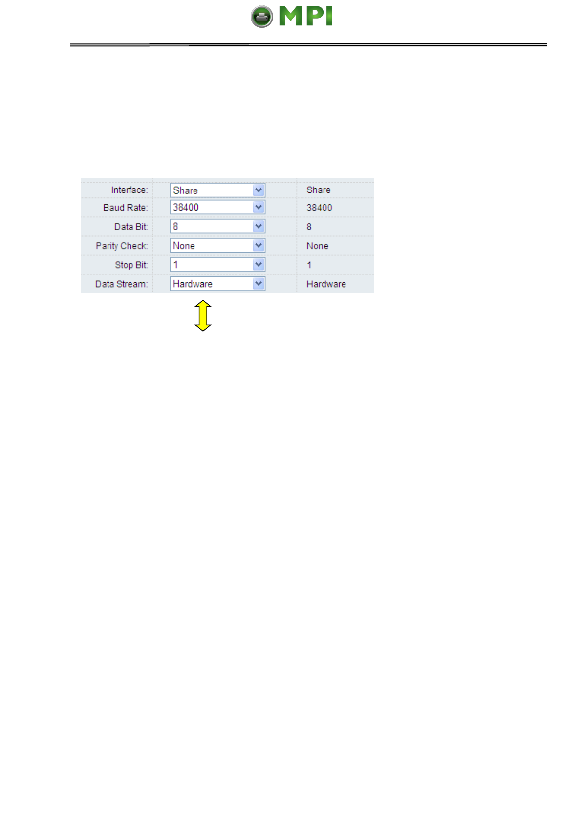
Tally Dascom 1140
Mantenimiento Periféricos Informáticos SL C/Canteras, 15 28860 Paracuellos de Jarama Tel: 00 34 917481604 WEB: https://mpi.com.es
Note:
1. The serial cable length should not exceed 15 meters.
2. Make sure the “Interface Setup” selects serial interface and the settings are the same
as PC communication port settings. Shown as below:
62
Page 78

Mantenimiento Periféricos Informáticos SL C/Canteras, 15 28860 Paracuellos de Jarama Tel: 00 34 917481604 WEB: https://mpi.com.es
Tally Dascom 1140
11 Character sets & Code Pages
11.1 Character Sets
Standard character set 1
Standard character set 2
63
Page 79

Mantenimiento Periféricos Informáticos SL C/Canteras, 15 28860 Paracuellos de Jarama Tel: 00 34 917481604 WEB: https://mpi.com.es
Tally Dascom 1140
IBM character set 1
IBM character set 2
64
Page 80

Mantenimiento Periféricos Informáticos SL C/Canteras, 15 28860 Paracuellos de Jarama Tel: 00 34 917481604 WEB: https://mpi.com.es
Tally Dascom 1140
OCR-A character set 1
OCR-A character set 2
65
Page 81

Mantenimiento Periféricos Informáticos SL C/Canteras, 15 28860 Paracuellos de Jarama Tel: 00 34 917481604 WEB: https://mpi.com.es
Tally Dascom 1140
OCR-B character set 1
OCR-B character set 2
66
Page 82

Country
Basic Command
USA
<ESC>“R”CHR$(0)
FRANCE
<ESC>“R”CHR$(1)
GERMANY
<ESC>“R”CHR$(2)
UK
<ESC>“R”CHR$(3)
DENMARK 1
<ESC>“R”CHR$(4)
SWEDEN
<ESC>“R”CHR$(5)
ITALY
<ESC>“R”CHR$(6)
SPAIN 1
<ESC>“R”CHR$(7)
JAPAN
<ESC>“R”CHR$(8)
NORWAY
<ESC>“R”CHR$(9)
DENMARK 2
<ESC>“R”CHR$(10)
SPAIN 2
<ESC>“R”CHR$(11)
LATINAMERICA
<ESC>“R”CHR$(12)
DENMARK/NORWAY
<ESC>“R”CHR$(13)
CHINA
<ESC>“R”CHR$(16)
Mantenimiento Periféricos Informáticos SL C/Canteras, 15 28860 Paracuellos de Jarama Tel: 00 34 917481604 WEB: https://mpi.com.es
Tally Dascom 1140
International Character Set Commands
International character sets
67
Page 83

Code Page
ESC R Parameter
CP 437
80
CP 737
93
CP 850
82
CP 851
88
CP 852
87
CP 857
8D
CP 858
9E
CP 860
84
CP 861
94
CP 863
85
CP 1252
72
CP 1253
73
CP 1254
74
8859-1
25
8859-1 (SAP)
2B
8859-2
26
8859-5
2A
8859-7
2D
8859-9
2E
8859-15
2F
Kamenicky
91
Mazovia
92
866 Bulgaria
9D
CP 1250
70
CP 1251
71
BRASCII
6D
Abicomp
6E
CP 865
86
CP 866
8E
CRO-ASCII
3C
Mantenimiento Periféricos Informáticos SL C/Canteras, 15 28860 Paracuellos de Jarama Tel: 00 34 917481604 WEB: https://mpi.com.es
Tally Dascom 1140
11.2 Code Page Commands
68
Page 84

Mantenimiento Periféricos Informáticos SL C/Canteras, 15 28860 Paracuellos de Jarama Tel: 00 34 917481604 WEB: https://mpi.com.es
Tally Dascom 1140
11.3 Code Page Tables
CP 437
CP 737
69
Page 85

Mantenimiento Periféricos Informáticos SL C/Canteras, 15 28860 Paracuellos de Jarama Tel: 00 34 917481604 WEB: https://mpi.com.es
Tally Dascom 1140
CP 850
CP 851
70
Page 86

Mantenimiento Periféricos Informáticos SL C/Canteras, 15 28860 Paracuellos de Jarama Tel: 00 34 917481604 WEB: https://mpi.com.es
Tally Dascom 1140
CP 852
CP 857
71
Page 87

Mantenimiento Periféricos Informáticos SL C/Canteras, 15 28860 Paracuellos de Jarama Tel: 00 34 917481604 WEB: https://mpi.com.es
Tally Dascom 1140
CP 858
CP 860
72
Page 88

Mantenimiento Periféricos Informáticos SL C/Canteras, 15 28860 Paracuellos de Jarama Tel: 00 34 917481604 WEB: https://mpi.com.es
Tally Dascom 1140
CP 861
CP 863
73
Page 89

Mantenimiento Periféricos Informáticos SL C/Canteras, 15 28860 Paracuellos de Jarama Tel: 00 34 917481604 WEB: https://mpi.com.es
Tally Dascom 1140
CP 1252
CP 1253
74
Page 90

Mantenimiento Periféricos Informáticos SL C/Canteras, 15 28860 Paracuellos de Jarama Tel: 00 34 917481604 WEB: https://mpi.com.es
Tally Dascom 1140
CP 1254
8859-1
75
Page 91

Mantenimiento Periféricos Informáticos SL C/Canteras, 15 28860 Paracuellos de Jarama Tel: 00 34 917481604 WEB: https://mpi.com.es
Tally Dascom 1140
8859-1 (SAP)
8859-2
76
Page 92

Mantenimiento Periféricos Informáticos SL C/Canteras, 15 28860 Paracuellos de Jarama Tel: 00 34 917481604 WEB: https://mpi.com.es
Tally Dascom 1140
8859-5
8859-7
77
Page 93

Mantenimiento Periféricos Informáticos SL C/Canteras, 15 28860 Paracuellos de Jarama Tel: 00 34 917481604 WEB: https://mpi.com.es
Tally Dascom 1140
8859-9
8859-15
78
Page 94

Mantenimiento Periféricos Informáticos SL C/Canteras, 15 28860 Paracuellos de Jarama Tel: 00 34 917481604 WEB: https://mpi.com.es
Tally Dascom 1140
Kamenicky
Mazovia
79
Page 95

Mantenimiento Periféricos Informáticos SL C/Canteras, 15 28860 Paracuellos de Jarama Tel: 00 34 917481604 WEB: https://mpi.com.es
Tally Dascom 1140
866 Bulgaria
CP 1250
80
Page 96

Mantenimiento Periféricos Informáticos SL C/Canteras, 15 28860 Paracuellos de Jarama Tel: 00 34 917481604 WEB: https://mpi.com.es
Tally Dascom 1140
CP 1251
BRASCII
81
Page 97

Mantenimiento Periféricos Informáticos SL C/Canteras, 15 28860 Paracuellos de Jarama Tel: 00 34 917481604 WEB: https://mpi.com.es
Tally Dascom 1140
Abicomp
CP 865
82
Page 98

Mantenimiento Periféricos Informáticos SL C/Canteras, 15 28860 Paracuellos de Jarama Tel: 00 34 917481604 WEB: https://mpi.com.es
Tally Dascom 1140
CP 866
CRO-ASCII
83
Page 99

Command
Function
BEL
Beeper
BS
Backspace
HT
Horizontal Tab
LF
Line Feed
VT
Vertical Tab
FF
Form Feed
CR
Carriage Return
SO
Double-Wide Printing 1 Line
SI
Select Condensed Mode
DC2
Cancel Condensed Mode
DC4
Cancel Double-Wide Printing 1 Line
CAN
Cancel Line
ESC SO
Double-Wide Printing 1 Line
ESC SI
Select Condensed Mode
ESC SP
Set Inter Character Space
ESC !
Master Select
ESC #
Cancel MSB Control
ESC $
Set absolute horizontal print position
ESC %
Select user-defined set
ESC &
Define user-defined characters
ESC ( -
Select line/score
ESC ( B
Bar code setup and print
ESC ( C
Set page length in define unit
ESC ( G
Select graphics mode
ESC ( U
Set unit
ESC ( V
Set absolute vertical print position
ESC ( ^
Print data as characters
ESC ( c
Set page format
ESC ( t
Assign character table
ESC ( v
Set relative vertical print position
ESC *
Select bit image
ESC +
Select n/360” Line Spacing
ESC -
Auto Underscore
ESC .
Print raster graphics
ESC 0
Select 1/8” Line Spacing
ESC 2
Select 1/6” Line Spacing
ESC 3
Set Graphics Line Spacing (n/180”)
ESC 4
Select Italic Mode
ESC 5
Cancel Italic Mode
ESC 6
Enable Printable Characters
ESC 7
Enable Upper Control Codes
Mantenimiento Periféricos Informáticos SL C/Canteras, 15 28860 Paracuellos de Jarama Tel: 00 34 917481604 WEB: https://mpi.com.es
Tally Dascom 1140
12 Control Codes Summary
12.1 ESC/P2 Emulation Command List
84
Page 100

Command
Function
ESC :
Copy ROM to RAM
ESC <
Select Unidirectional Mode 1 Line
ESC =
Set MSB to 0
ESC >
Set MSB to 1
ESC ?
Reassign Graphics Mode
ESC @
Initialize Printer
ESC A
Set n/60” Line Spacing
ESC B
Set Vertical Tabs
ESC C
Set Page Length in Lines
ESC C 0
Set Page Length in Inches
ESC D
Set horizontal tabs
ESC E
Select Emphasized Mode
ESC F
Cancel Emphasized Mode
ESC G
Select Double-strike Mode
ESC H
Cancel Double-strike Mode
ESC J
Advance print position
ESC K
Select 60-dpi graphics
ESC L
Select 120-dpi graphics
ESC M
Select 12 cpi
ESC N
Set bottom margin
ESC O
Cancel bottom margin
ESC P
Select 10 cpi
ESC Q
Set right margin
ESC R
Select an international character set and code page
ESC S
Select Subscript or Superscript Printing
ESC T
Cancel Subscript or Superscript Printing
ESC U
Turn unidirectional mode on/off
ESC W
Turn Double-wide Mode On/Off
ESC Y
Select 120-dpi, double-speed graphics
ESC Z
Select 240-dpi graphics
ESC \
Set relative horizontal print position
ESC c
Set horizontal motion index(HMI)
ESC g
Select 15 cpi
ESC k
Select Typestyle Family
ESC l
Set left margin
ESC p
Turn Proportional Mode On/Off
ESC q
Select Character Style
ESC t
Select character table
ESC w
Turn Double-high Mode On/Off
ESC x
Select Letter Quality or Draft
ESC y
Select draft/super draft
ESC Y
Select High-speed Double-density Graphics Mode
DEL
Delete Character
Mantenimiento Periféricos Informáticos SL C/Canteras, 15 28860 Paracuellos de Jarama Tel: 00 34 917481604 WEB: https://mpi.com.es
Tally Dascom 1140
85
 Loading...