

Page 1

TECHNICAL MANUAL
OPERATOR'S, ORGANIZATIONAL, DIRECT
SUPPORT, AND GENERAL SUPPORT
BASE
NSN 4120-01-122-0629
MAINTENANCE
AIR CONDITIONER,
MOUNTED, AIR COOLED,
Hz,
MANUAL
HEADQUARTERS, DEPARTMENT OF THE ARMY
21 OCTOBER 1983
Page 2

Page 3

WARNINGS
TM5-4120-375-14
Disconnect main power
connector before attempting any electrical servicing of
air conditioner.
Dry cleaning solvent,
dangerous to personnel and property.
P-D-680 or P-S-661, used to clean parts is potentially
Avoid repeated and prolonged skin contact.
Do not use near open flame or excessive heat. Flash point of solvent is 100
degrees F (38 degrees C).
Avoid bodily contact with liquid refrigerant and avoid inhaling refrigerant gas.
Be especially careful that Refrigerant 22 does not come in contact with eyes.
In case of refrigerant leaks, ventilate area immediately.
Do not use compressed air for cleaning purposes except where reduced to less
than 30 psi and then only with effective chip guarding and personal protective
equipment.
Purge system with dry nitrogen prior to soldering.
Refrigerant heated to 1200
degrees F creates phosgene gas.
Be careful when working with high voltage. Failure
to comply can result in
serious injury or death.
The air conditioner must be grounded prior to operation. Connect one end of a
number 6AWG (American Wire Gage) copper wire ground lead to an underground
metallic water piping system or a driven metal ground rod or buried metal plate.
Connect the other end of the ground lead to the grounding bolt on the upper left
front corner of the unit.
Refrigerant-22 is contained in the refrigerant system under high pressure.
Extreme care must be exercised to prevent refrigerant from coming in contact
with exposed skin and eyes.
Provide adequate ventilation when discharging the
system in a confined area.
Polyurethane foam insulation breaks down to form toxic gases when heated to
brazing temperature.
All refrigerant gas must be discharged from system before
performing any removal procedures of refrigerant components.
Avoid contact with refrigerant acid.
Burns could result from contact with
refrigerant.
Acetone and methylethyl ketone are flammable and their vapors are explosive.
Prolonged or repeated inhalation of fumes on contact with the skin can be toxic.
Use in a well ventilated area, wear gloves and keep away from sparks or flame.
Scrape or pull off as much of the damaged insulation as possible. Soften the
remaining insulation and adhesive with acetone on MEK.
a
/(b blank)
Page 4

Page 5

TM 5-4120-375-14
C3
CHANGE
NO. 3
WASHINGTON, D.C., 28 February 1995
HEADQUARTERS
DEPARTMENT OF THE ARMY
Operator’s, Organizational, Direct Support, and
General Support Maintenance Manual
AIR CONDITIONER, BASE MOUNTED, AIR COOLED,
208 VAC, 3-PHASE, 60 HZ, SINGLE PACKAGE, 36,000 BTU/HR
PART NO. 97403-13219E0790
MODEL UAC40-5/6-08, NSN 4120-01-122-0629
MODEL 2463T100-1 , NSN 4120-01-218-6912
DISTRIBUTION STATEMENT A: Approved for public release; distribution is unlimited
TM 5-4120-375-14, 21 October, 1983, is changed as follows:
1. Remove and insert pages as indicated below. New or changed text material is indicated by a vertical bar
in the margin. An illustration change is indicated by a miniature pointing hand.
Remove pages Insert pages
E-3
and
E-4
2. Retain this sheet in front of manual for reference purpose.
By
Order of the Secretary of the Army:
E-3
and E-4
General, United States Army
Official:
MILTON H. HAMILTON
Administrative Assistant to the
Secretary of the Army
DISTRIBUTION:
To be distributed in accordance with DA
TM 5-4120-375-14.
08105
Form 12-25-E,
block no. 0028, requirements for
GORDON R. SULLIVAN
Chief of Staff
Page 6

Page 7

Page 8

Page 9

Page 10

Page 11

TM 5-4120-375-14
HEADQUARTERS
DEPARTMENT OF THE ARMY
WASHINGTON, D.C., 21 October 1983
OPERATOR’S, ORGANIZATIONAL, DIRECT SUPPORT,
AIR CONDITIONER, BASE MOUNTED, AIR COOLED,
208
VAC, 3-PHASE, 60 HZ,
SINGLE PACKAGE, 36,000 BTU/HR
PART NO. 97403-13219E0790
CHAPTER 1
Section I
Section II
Section III
MODEL
UAC40-5/6-08
2463T100-1
TABLE OF CONTENTS
NSN
4120-01-122-0629
4120-01-218-6912
1-1
1-3
1-6
CHAPTER 2
Section I
Section II
Section III
2-1
2-1
2-5
Change 1
i
Page 12

TM5-4120-375-14
TABLE OF CONTENTS (continued)
Page
Section
CHAPTER
Section
Section
CHAPTER
Section
Section
Section
Section
Section
Section
CHAPTER
IV.
3.
I.
II.
4.
I.
II.
III.
IV.
V.
VI.
5.
Operation Under
Unusual conditions ---------------
2-7
OPERATOR’S MAINTENANCE INSTRUCTIONS
Lubrication Instructions -------------------------
Troubleshooting ----------------------------------
3-1
3-1
ORGANIZATIONAL MAINTENANCE INSTRUCTIONS
Repair Parts, Special Tools, TMDE,
and Support Equipment ---------------------------Service upon Receipt of Equipment ----------------
Preventive Maintenance Checks and Services ------Troubleshooting ----------------------------------Maintenance Procedures --------------------------Preparation for Storage or Shipment --------------
4-1
4-2
4-7
4-12
4-20
4-134
DIRECT SUPPORT MAINTENANCE INSTRUCTIONS
Section
Section
Section
CHAPTER
Section
Section
APPENDIX
I.
II.
III.
6.
I.
II.
A.
B.
C.
D.
E.
F.
Repair parts, Special Tools TMDE,
and Support Equipment ---------------------------Troubleshooting ---------------------------------Maintenance Procedures ---------------------------
5-1
5-2
5-7
GENERAL SUPPORT MAINTENANCE INSTRUCTIONS
Troubleshooting
------------------------ -----------
Maintenance Procedures ----------------------------
References --------------------------------------Maintenance Allocation Chart ---------------------
Components of End Item List ----------------------
Expendable Supplies And Materials List ----------Wire List and Diagram
Glossary
------------------------ -----------------
------------------------ ----
6-1
6-2
A-1
B-1
C-1
D-1
E-1
F-1
ii
ALPHABETICAL INDEX
------------------------- ---------
INDEX- 1
Page 13

TM5-4120-375-14
CHAPTER 1
INTRODUCTION
CHAPTER OVERVIEW
The purpose of this chapter is twofold:
a. To provide you with the standard data required in all manuals
(i.e. forms and record data).
b.
To acquaint you with the air conditioner. This is done by
giving you a physical and functional description of those
major equipment parts that you are likely to come in contact
with.
INDEX
PAGE
I.
II.
III.
General Information.
Equipment Description.
Technical Principles of Operation.
SECTION I. GENERAL
1.
Fresh air dampers
2.
Air filter panel
Return air damper
3.
4.
Condenser coil guard
Main
5.
6.
7.
8.
9.
power connector
Rotary control switch
Thermostat
Evaporator fan outlets
Maintenance panel
1-1
1-3
1-6
INFORMATION
1-1
Page 14

TM5-4120-375-14
1-1.
SCOPE .
a.
Type of Manual: Operator’s, Organizational, Direct
Support, and
General Support Maintenance.
b.
Model Number and Equipment Name: Unifab Industries
Inc. model number
UAC 40-5/6-08, Talley Corporation model number 2463T100-1, Air
conditioner 36,000 BTU/HR, Base Mounted, 208 volt, 3 Phase, 50/60
Cycle, AC, Single Package.
c.
Purpose of Equipment:
Provide filtered, cooled air to a desired
predetermined range and circulating the air to provide cooling of
equipment or personnel within the air conditioned area.
1-2.
MAINTENANCE FORMS AND RECORDS.
Department of the Army forms and procedures used for equipment maintenance will
be those prescribed by DA PAM 378-750, the Army Maintenance Management Systems
(TAMMS).
1-3.
DESTRUCTION OF ARMY MATERIAL TO PREVENT ENEMY USE.
Refer to TM 750-244-3, Procedures for Destruction of Equipment to Prevent Enemy
use, for information about destruction.
1-4.
PREPARATION FOR STORAGE OR SHIPMENT.
Instructions for preparation for storage and shipment are in Chapter 4.
1-5.
If your air conditioner needs Improvement, let us know. Send us an EIR. Y
the user,
equipment.
is hard to perform.
REPORTING EQUIPMENT IMPROVEMENT RECOMMENDATIONS (EIRs).
OU
,
are the only one who can tell us what you do or do not like about your
Let us know why you do not like the design.
Put it on an SF 368 Quality Deficiency Report.
Tell us why a procedure
Mail it
directly to Commander, U.S. Army Troop Support Command, ATTN: AMSTR-QX, 4300
Goodfellow Boulevard, St. Louis; MO 63120-1798.
1-2
Change 1
Page 15

SECTION II. EQUIPMENT DESCRIPTION
TM5-4120-375-14
1-6.
PURPOSE OF AIR CONDITIONER.
The air conditioner is used primarily in van type enclosures. The units provide
filtered, cooled air, as required,
to maintain the service conditions necessary
for the efficient operation of electronic equipment in the vans. The air
conditioner also provide for the comfort of operating personnel housed within
the vans.
1-7.
CAPABILITIES AND FEATURES.
a. Base mounted and air cooled.
b.
Electric motor driven and designed for continuous operation under
varying loads.
c.
Furnishes air circulation.
d.
Furnishes 36,000 BTU/HR for cooling.
e. Furnishes fresh air.
1-3
Page 16

TM5-4120-375-14
1-8.
LOCATION AND DESCRIPTION OF MAJOR COMPONENTS.
Compressor
1.
Evaporator coil
2.
Evaporator fan motor
3.
4.
Expansion valve
Condenser coil
5.
6.
Junction box
Dual pressure switch
7.
Solenoid valve
8.
Condenser fan motor
9.
Dryer
10.
11.
Condensate drain exit
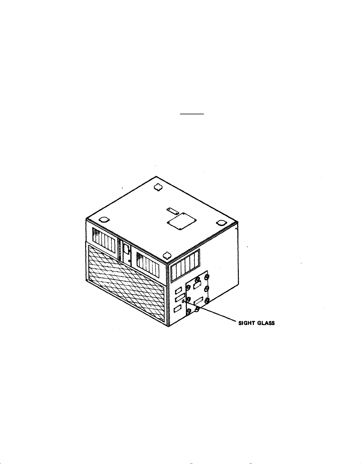
Sight glass
12.
1-4
Page 17

TM5-4120-375-14
1-9. IDENTIFICATION.
The air conditioner has one identification plate, it is located on the front
panel.
It provides the Air Conditioner nomenclature, national stock number,
part number, contract number, serial number, and weight.
1-10.
Air Conditioner, Base Mounting
Unifab Industries, Inc.
UAC 40-5/6-08
4120-01-122-0629
The Talley Corporation
2463T100-1
4120-01-218-6912
97403-13219E0790
36.92 IN. ( .93 m)
42.34 IN. (1.07 m)
27.85 IN. ( .70 m)
475 lbs. (215 kg)
8.5 kw
36,000 BTU/HR
208
60
3
Change 1
1-5
Page 18

TM5-4120-375-14
1-11.
SECTION III.
GENERAL.
TECHNICAL PRINCIPLES OF OPERATION
The air conditioner is a base mounted, self-contained, electric motor driven
unit that provides
36,000 BTU/HR for cooling.
Once started, it operates
automatically due to the relationship of the components, controls and
instruments.
1-12.
VENTILATION.
Placing the selector switch in the FAN position energizes the fan motor which
forces air out of the evaporator
ventilation is determined by the
fan guard. The amount of outdoor air used for
position of the damper control knobs.
1-6
Page 19

TM5-4120-375-14
1-13.
COOLING.
With the selector switch in the COOL position the fan motors and the compressor
are energized.
The fan motors and compressor run continuously. The thermostat
controls the amount of cooling.
1-7/(1-8 blank)
Page 20

Page 21

TM5-4120-375-14
CHAPTER 2
OPERATING INSTRUCTIONS
CHAPTER OVERVIEW
This chapter contains a functional description of’ the major components of the
air conditioner.
It explains how to operate the Air Conditioner.
For your
convenience, below is an index of’ this chapter.
INDEX
SECTION
I.
II.
III.
IV.
2-1.
GENERAL.
TITLE PAGE
Instructions
Under Usual Conditions
Under Unusual Conditions
Preventive Maintenance Checks and Services
SECTION I.
2-1
2-5
2-7
2-2
2-1
Page 22

TM5-4120-375-14
SECTION II. PREVENTATIVE MAINTENANCE CHECKS AND SERVICES
2-2.
GENERAL.
Preventative Maintenance Checks and Services (PMCS, Table 2-1.)
are to be completed to ensure the air conditioner is ready to use at
all times.
defects before the air
2-3.
PMCS PROCEDURES.
a.
These checks and services help you find and repair
conditioner is damaged or fails.
Item numbers
in the first column of Table 2-1 are the order in
which inspections are to be done. Column two “Interval” lists when
to do them.
b.
If minor defects are found when the air conditioner is running
take notes on what they are and notify organizational maintenance.
CAUTION
While the air conditioner is running, if any defect develops
that you think will damage the air condiitioner, stop it at once.
2-2
Page 23

TM5-4120-375-14
Table 2-1.
Operator/Crew
If the equipment must be kept in continuous operation, check
and service only those items that can be checked and serviced
without disturbing operation. Hake the complete checks and
services when
the equipment can be shut down.
B-Before Operation
ITEM INTERVAL ITEM TO BE
NO.
1
BDA
*
INSPECTED
Inspect controls and fittings
for defective or loose parts.
2
*
Screens and Grilles (Cheek for dirt and obstructions).
Preventive Maintenance Checks
NOTE
D-During Operation
PROCEDURE
and Services
A-After Operation
EQUIPMENT
IS NOT READY/
AVAILABLE IF:
2-3
Page 24

TM5-4120-375-14
TABLE 2-1.
B-Before Operation
OPERATOR/CREW PREVENTIVE MAINTENANCE CHECKS AND SERVICE
D-During Operation
A-After Operation
-------------------- ------------------------- ------------------------ ----ITEM INTERVAL
NO.
BDA
ITEM TO BE
INSPECTED
PROCEDURE
EQUIPMENT
IS NOT READY/
AVAILABLE IF:
3
4
5
6*
*
*
*
Be careful when working with high voltage.
Sight Glass (Check for cloudy or bubbles).
Damper Control (Check for Freedom of movement).
Noise or Vibration (Listen for any unusual noise or vibration).
Panels (Check for damage).
Failure to comply can result
in serious injury or death.
7*
Main Power Connector (Inspect for loose connection).
2-4
Page 25

TM5-4120-375-14
2-4.
2-5.
SECTION III.
OPERATION UNDER USUAL CONDITIONS
PREPARATION FOR USE.
a. Inspect the entire unit for external damage. Report any
deficiencies to the proper maintenance level.
Be careful
in serious
b.
Connect power.
when working with
injury or death.
high voltage.
Failure to comply can result
c. Perform preventive maintenance checks and services.
STARTING THE EQUIPMENT.
Before you operate: Always keep in mind the CAUTIONS AND WARNINGS.
a. Ventilation mode.
(1).
(2).
Turn rotary control switch to FAN position.
Adjust damper to admit fresh air as desired.
2-5
2-5
Page 26

TM5-4120-375-14
2-5.
STARTING THE EQUIPMENT (cont.).
CAUTION
Assure that crankcase heater is on six hours prior to operating.
NOTE
For maximum cooling capacity when outside temperature is
high, set damper controls at full MIN position.
b.
Cooling mode.
(1).
(2).
(3)0
Set thermostat for desired
Turn rotary control switch
Turn damper control knobs to desired position from MIN
room temperature.
to
COOL.
(100% RETURN-AIR) to MAX (100% FRESH-AIR).
2-6
Page 27
TM5-4120-375-14
2-6.
Allow 15 minutes operation to ensure unit has stabilized, then check
sight glass for cloudiness.
OPERATION.
If unit does not operate, refer to
troubleshooting procedures in Chapter 3 of this manual.
CAUTION
Check sight glass for bubbles or yellow color.
If sight glass is bubbly yellow color, notify Direct Support
Maintenance.
If the glass is free of bubbles and the dot is
green, the system is properly charged.
Change 1
2-7
Page 28
TM5-4120-375-14
2-7.
2-8.
STOPPING.
Turn rotary control switch to OFF position.
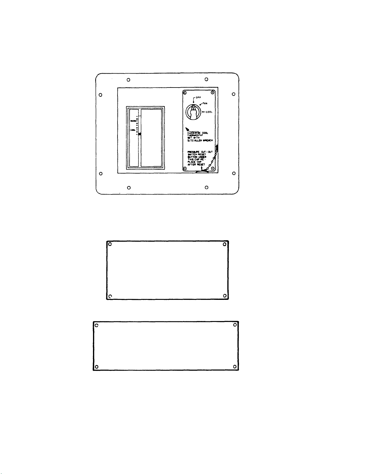
OPERATIONAL INSTRUCTION WARNING PLATES.
DISCONNECT
MAIN POWER PLUG
BEFORE SERVICING ELECTRICAL
SYSTEM
OPERATE
ONLY WITH PANEL
INSTALLED
2-8
Page 29

SECTION IV OPERATION UNDER UNUSUAL CONDITIONS
TM5-4120-375-14
2-9.
OPERATION IN EXTREME COLD.
a. Keep entire unit free of snow and ice.
Cover unit when not in use.
b.
2-10.
b. Cut amount of fresh air used.
2-11. OPERATION IN DUSTY OR SANDY AREAS.
2-12. OPERATION UNDER RAINY OR HUMID CONDITIONS.
a. Keep unit clean and dry.
b. Cover unit when not in use.
c. Remove cover during dry periods and allow unit to
dry.
2-13. OPERATION IN SALT WATER AREAS.
a. Rinse with clean water and dry as much of unit as possible to
prevent corrosion.
b.
Cover
unit when not in use.
2-14. OPERATION IN HIGH ALTITUDES.
a. The operating efficiency of the unit will be reduced at higher
altitudes.
2-9/(2-10 blank)
Page 30

Page 31

TM5-4120-375-14
CHAPTER
3
OPERATOR'S MAINTENANCE INSTRUCTIONS
CHAPTER OVERVIEW
This chapter contains all the necessary maintenance instructions to keep your
air conditioner in good repair.
INDEX
SECTION
I.
II.
III.
TITLE
Lubrication Instructions.
Operator Troubleshooting.
Operator Troubleshooting Table.
PAGE
3-1
3-1
3-2
SECTION I.LUBRICATION INSTRUCTIONS
3-1.
There is no lubrication required for this air conditioner.
SECTION II.
TROUBLESHOOTING
3-2.
GENERAL.
a. Table
3-1
provides information useful in diagnosing and
correcting malfunctions which you may find during the operation
of
or maintenance
the unit or its components.
Perform the
tests/inspections and corrective actions in the order listed.
b.
This manual cannot list all malfunctions that may occur, nor
all tests or inspections and corrective actions.
If a
malfunction is not listed or is not corrected by listed
corrective actions, notify your supervisor.
3-1
Page 32

TM5-4120-375-14
SECTION III. OPERATOR TROUBLESHOOTING TABLE
TABLE
3-1
OPERATOR TROUBLE SHOOTING TABLE
MALFUNCTION
TEST OF INSPECTION
VENTILATION MODE (ONLY)
1.
AIR CONDITIONER FAILS TO OPERATE.
Be careful when working with high voltage.
in serious injury or death.
Step 1.
Check to see if main power cord is plugged in.
Connect power cable to air conditioner.
Step 2.
Check to see that power supply circuit breaker is in the
ON position.
CORRECTIVE ACTION
WARNING
Failure to comply can result
Step 3.
Place circuit breaker to the ON position.
Check to see if selector switch is in fan position.
Place selector switch in fan position.
3-2
Page 33

TM5-4120-375-14
TABLE 3-1
OPERATOR TROUBLESHOOTING TABLE (cont.)
------------------------------------------------------------------------------MALFUNCTION
TEST OF INSPECTION
CORRECTIVE ACTION
-----------------------------------------------------------------------------
COOLING MODE
2.
INSUFFICIENT
Step 1.
COOLING.
Check to see if selector switch is in COOL position.
Place selector switch in COOL position.
Step 2.
Check
to see
if THERMOSTAT is in COOLER position.
Notify Organizational Maintenance.
Step 3. Inspect air filter and return air grilles for
obstructions.
Notify Organizational Maintenance.
Step 4. Inspect sight glass for bubbles.
Notify Organizational Maintenance.
3-3
/(3-4 blank)
Page 34

Page 35

CHAPTER 4
TM5-4120-375-14
ORGANIZATION MAINTENANCE
This chapter contains the following frequently
INSTRUCTIONS
used maintenance information.
The symptom index on page 4-12 is a guide to the troubleshooting information.
There is also an index to the maintenance procedures on page 4-21.
INDEX
SECTION
TITLE
I . Repair Parts, Special Tools, TMDE, and Support Equipment
II. Service Upon Receipt
III. Preventive Maintenance Checks and Services
IV.
V.
VI.
Troubleshooting
Maintenance Procedures
Preparation for Shipment or Storage
Page
4-1
4-2
4-7
4-12
4-20
4-134
For authorized common tools and equipment, refer to the
TabIe of Organizational and Equipment (MTOE) applicable
4-2.
N
SPECIAL TOOLS, TMDE, AND SUPPORT EQUIPMENT.
O special tools, TMDE, or support equipment are required for this
Modified
to your unit.
air conditioner.
4-3.
REPAIR PARTS.
Repair parts are listd and illustrated in TM 5-4120-375-24P.
Page 36

TM5-4120-375-14
SERVICE UPON RECEIPT
4-4.
SECTION II.
UNLOADING THE EQUIPMENT.
The crated air conditioner may be unloaded and moved by any means, provided
the unit weight is supported by the base platform.
4-5.
UNPACKING THE EQUIPMENT.
CAUTION
So that the unit is protected,
it should be left crated until moved
to the location where it is to be installed.
a.
General.
To uncrate the unit,
and lift off the top.
remove the bands from the top panel
Remove sides in a similar manner.
The unit is then ready for inspection.
b.
Depreservation. Prepare the air conditioner for
operation as outlined on DA Form
inspection and
2258
(depreservation Guide for Vehicles and Equipment.
4-6.
INSPECTING AND SERVICING EQUIPMENT.
a.
Inspect the entire air conditioning unit, including motors, fans,
controls, etc.,
to be certain that all parts have been received and
without damage. Report any deficiencies to the proper maintenance
level.
CAUTION
Do not remove tags from equipment until the instructions have been
followed. Failure to follow these instructions can result in serious
damage to the equipment.
b.
Test the joints in the refrigerant circuit for leaks in accordance
with paragraph
5-17.
4-2
Page 37

TM5-4120-375-14
4-7.
1.
SERVICE UPON RECEIPT CHECKLIST.
Exterior
Panels and Grilles
a.
b.
2.
Front
Control Box
a.
b.
Front Panel Main Power Connector a.
3.
b.
Inspect for signs of rough
handling and damage.
Service or reject any component
if damage prevents the air
conditioner from working.
Check for broken or damaged knob.
Insure that switches move freely
from position to position.
Repair any component that is found
to be malfunctioning.
Inspect main power connector
for damage.
Repair of replace main
power connector.
properly.
4-3
Page 38

TM5-4120-375-14
4-7.
SERVICE UPON RECEIPT CHECKLIST. (cont.)
LOCATION
Side
5.
ITEM
Return Air Damper
ACTION
b.
Remove air filters and inspect
the filter for accumulation of
dirt.
c.
Clean filter.
a.
Check to see that the FRESH AIR
control moves freely between the
the MIN and MAX position and that
the return air damper opens and
closes properly.
b.
Adjust or repair FRESH AIR controls.
4-4
Page 39

TM5-4120-375-14
4-8.
INSTALLATION INSTRUCTIONS.
a.
The unit may be supported by, or suspended from, any convenient
part of the van or trailer capable of withstanding a concentrated
load of approximately 550 pounds (292 kg.).
b.
If the unit is to be mounted
near a wall or partition, allow
clearance to permit removal of panels.
c.
Follow the base plan in figures below in selecting a suitable location
or in constructing an installation base. Lift unit by lifting rings
only.
4-5
Page 40

TM5-4120-375-14
4-8.
INSTALLATION INSTRUCTIONS.
d.
Connect a 1/2 inch threaded pipe to the drain connections on
(cont.)
the bottom right side of the unit to remove condensate water.
Extend piping or hose to deposit water in a suitable location or
container. Drain system must have
"U" trap on exterior drain
line.
e.
Be sure the main rotary switch on the control box is in the OFF
position, and connect a 208 volt, 60 cycle, 3 phase power source
to the main power connector at the lower right front corner of
the unit.
WARNING
The air conditioner must be grounded prior to
operation. Connect one end of a
number 6AWG (American Wire Gage) copper wire ground lead to an underground
metallic water piping system or a driven metal ground rod or buried metal
plate. Connect the other end of the ground lead to the grounding bolt on the
upper left front corner of the unit.
f.
The new unit should not require servicing, as it is shipped
completely assembled and ready to operate when power is
applied.
However, if any defects have been found during the
inspection of the equipment they should be corrected as necessary
before the unit is placed into operation.
4-6
Page 41

TM5-4120-375-14
SECTION III.
4-9.
GENERAL.
To insure that the air conditioner is ready for
be inspected systematically so that the defects
before the result is serious damage or failure.
operation of the unit shall be noted for future
as an operation has ceased.
if operation were to continue.
ORGANIZATIONAL
operation at all times, it must
may be discovered and oorrected
Defects discovered during
corrections to be made as soon
Stop operation which would damage the equipment
All deficiencies and shortcomings shall be
recorded together with the corrective action taken on DA Fom 2404 "Equipment
Inspection and Maintenance Worksheet",
equipment fails to operate, troubleshoot with proper equipment.
at the earliest opportunity. If your
Report any
deficiencies using proper forms, (See DA PAM 738-750).
4-10. PREVENTIVE MAINTENANCE CHECKS AND SERVICES (PMCS).
Dry cleaning solvent, P-D-680, or P-S-661, used to clean
parts is potentially dangerous to personnel and property.
Avoid repeated and prolonged skin contact. Do not use
near open flame or excessive heat.
is 100 degrees F
(38 degrees C).
Flash point of solvent
Do not use compressed air for cleaning purposes except where
reduced to less than 30 psi (2.11 km/ cm 2) and then only with
effective chip guarding and personal protective equipment.
Change 1
4-7
Page 42

TM5-4120-375-14
Table 4-1.
ORGANIZATIONAL PREVENTIVE MAINTENANCE CHECKS AND SERVICES.
M-Monthly Q-Quarterly
ITEM INTERVAL
NO.
1.
2.
3.
MQS
*
*
*
ITEM TO BE
INSPECTED
Controls and
fittings
Refrigeration
components
Fresh air filters
PROCEDURE EQUIPMENT
Check for defective
or loose parts. or replace
Check for visable
and audible leaks.
Check for dirt or
damage.
S-Semiannually
IS NOT READY/
AVAILABLE IF:
If damaged repair
controls in
accordance with
paragraph 4-16.
If leak exist
notify Direct
Support Maintenance.
Replace fresh
air filters in
accordance with
paragraph 4-19.
4-8
Page 43
TM5-4120-375-14
Table 4-1. ORGANIZATIONAL
---------------------------------------------------------------------------
ITEM
NO.
INTERVAL
MQS
ITEM TO BE PROCEDURE EQUIPMENT
INSPECTED IS NOT READY;
PREVENTIVE MAINTENANCE CHECKS
Q-Quarterly
AND SERVICES.
S-Semiannually
(cont.)
AVAILABLE IF’:
----------------------------------------------------------------------------
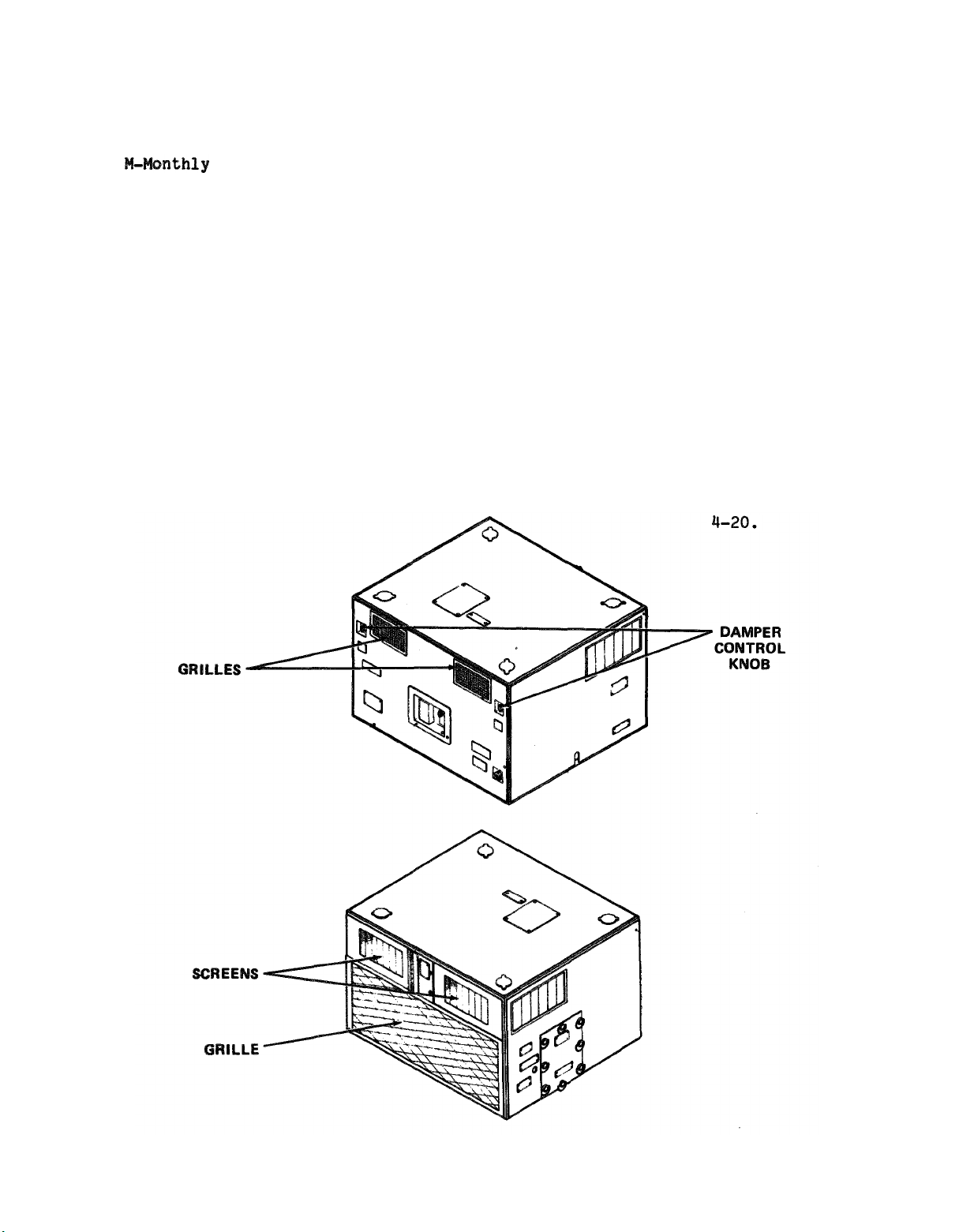
4.
5.
*
Screens and Grilles
*
Damper control
Check for dirt or
damage.
Check for freedom
of movement.
If damaged
repair or replace
screens and
grilles in
accordance with
paragraph 4-17
and 4-18.
Adjust or replace
damper control
in accordance
with paragraph
paragraph 4-20.
4-9
Page 44

TM5-4120-375-14
Table 4-1.
M-Monthly
ORGANIZATIONAL PREVENTIVE MAINTENANCE CHECKS AND SERVICES. (cont.)
Q-Quarterly
S-Semiannually
—---- ------------------------- --------------------- -------------------- ------
ITEM INTERVAL
NO.
MQS
ITEM TO BE
INSPECTED
PROCEDURE
EQUIPMENT
IS NOT READY/
AVAILABLE IF:
6.
*
Fans
Check for security
of attachment, bent
or broken blades.
If damaged repair
or replace fans
in accordance with
paragraphs
4-25
and 4-26.
7.
4-10
*
Thermostat
Check for proper
operation.
Inspect
for security of
If damaged repair
or replace
thermostat in
accordance with
paragraph 4-16.
Page 45

TM5-4120-375-14
Table 4-1.
ORGANIZATIONAL PREVENTIVE MAINTENANCE CHECKS AND SERVICES. (cont.)
M-Monthly
ITEM INTERVAL
No.
8.
9.
MQS
*
*
ITEM TO BE
INSPECTED
Evaporator coil
Condenser coil
Q-Quarterly
PROCEDURE
Check evaporator
coil for cleanliness.
Check for visible
and
audible leaks.
Check condenser
coil for cleanliness.
Check for visible
and audible leaks.
S-Semiannually
EQUIPMENT
IS NOT READY/
AVAILABLE IF:
If leaks exist
notify Direct
Support Maintenance.
If leaks exist
notify Direct
Support Maintenance.
Page 46

TM5-4120-375-14
4-11. TROUBLESHOOTING.
a.
Table 4-2 contains troubleshooting information for locating and cor-
recting most of the operating troubles which are the responsibility
of organizational maintenance. Each malfunction for an individual
component, unit, or system is followed by a list of tests or
inspections which will help you to determine probable causes and
corrective actions to take. Perform the tests/inspections and
corrective actions in the order listed.
b.
This manual cannot list all malfunctions that may occur, nor all
tests or inspections and corrective actions.
not listed or is not corrected by listed corrective actions, notify
your supervisor.
c.
Onlv those functions within the scope of organizational maintenance are listed.
of operator/crew maintenance, refer to Table 3-1
SECTION IV. TROUBLESHOOTING
If a malfunction is
For troubleshooting procedures within the scope
.
4-12. SYMPTOM INDEX.
Locate the malfunction which is the same, or most nearly the same,
as the trouble you are having with the air conditioner.
The Symptom
Index lists the first page of troubleshooting information for that
malfunction. Follow the steps one by one, and perform the corrective
actions listed.
Malfunction
Number Description
1.
2.
3.
4.
5.
Air conditioner fails to operate.
Compressor fails to start.
Insufficient cooling.
Evaporator fan fails to operate
Condenser fan fails to operate
Page
4-13
4-14
4-15
4-15
4-16
4-12
Page 47

TM5-4120-375-14
Table 4-2. TROUBLESHOOTING
--------------------------------------------------------------------------TEST OR INSPECTION
CORRECTIVE ACTION
----------------------------------------------------------------------
VENTILATION MODE ONLY
1.
AIR CONDITIONER FAILS TO OPERATE.
Be careful when working with high voltage. Failure to comply can result in
serious injury or death.
Step 1.
Step 2.
Step 3.
Step 4.
Step 5.
Check to see if main
Connect power
208VAC, three
Check to see if main
power is plugged in.
cable to a source suppling
phase, 60 Hz. power.
power connector is defective in
accordance with paragraph 4-23.
Replace defective main power connector in
accordance with paragraph 4-23.
Check for loose electrical connections.
Tighten electrical connections.
Check for defective wiring in accordance
with paragraph
4-24.
Replace defective wiring. Use identical
wire consult Appendix F-and solder (Item 12,
table D-1) all terminals connectors in
accordance with paragraph 4-24.
Check
to see that selector switch is in FAN position.
Place selector switch in FAN position. If
the air conditioner will NOT operate check
for a defective switch in accordance with
paragraph 4-16.
Replace defective switch
in accordance with paragraph 4-16.
4-13
Page 48

TM5-4120-375-14
Table 4-2.
MALFUNCTION
COMPRESSOR FAILS TO START.
2.
Step 1.
Step 2.
TROUBLESHOOTING (cont.)
TEST OR INSPECTION
CORRECTIVE ACTION
COOLING MODE
Loosen eight turnlock fasteners on maintenance panel.
Remove maintenance panel.
Place circuit breaker in the ON position. If
the air conditioner will not operate in the
COOL position, check for a defective circuit
breaker in accordance with paragraph 4-22.
Replace defective circuit breaker in
accordance with paragraph 4-22.
Check
to see if dual pressure switch contacts are
open.
Push reset button at the dual pressure switch.
If compressor does not start, stop air
conditioner. Notify Direct Support Maintenance.
WARNING
Be careful when working with high voltage.
Failure to comply can
result in serious injury or death.
Step 3.
Check to see that selector switch is in COOL
position.
Place selector switch in COOL position.
air conditioner will NOT operate check for a
defective switch in accordance with paragraph
4-16.
Replace defective switch in accordance with
paragraph 4-16.
If the
4-14
Page 49

TM5-4120-375-14
Table 4-2.
MALFUCTION
INSUFFICIENT COOLING.
3.
Step 1.
TROUBLESHOOTING (cont.)
TEST OR INSPECTION
CORRECTIVE ACTION
Check to see that thermostat (temperature control)
is set correctly.
Place thermostat in cooler position.
Replace defective thermostat in accordance
with paragraph 4-16.
Step 2.
Check for correct operation of evaporator fan
assembly.
Replace or repair damaged evaporator fan
assembly in accordance with paragraph 4-25.
4-15
Page 50

TM5-4120-375-14
MALFUNCTION
Step 3.
Step 4.
Table 4-2.
TROUBLESHOOTING (cont.)
TEST OR INSPECTION
CORRECTIVE ACTION
Check for correct operation of condenser fan assembly.
Replace or repair damaged condenser fan
assembly in accordance with paragraph
4-26.
Check
fresh air dampers.
Remove eight screws and eight rubber washers
securing lifting ring covers to top panel and
frame.
Remove lifting ring covers.
Remove twenty-three screws and eight screws
securing top panel to frame.
Remove top panel.
Inspect for freedom of movement, lubricate if
required (Item 17, table D-1).
Tighten loose mountings.
Replace or repair fresh air dampers, in
accordance with paragraph 4-20.
4-16
Page 51

TM5-4120-375-14
Table 4-2.
MALFUNCTION
TROUBLESHOOTING (cont.)
TEST OR INSPECTION
Step 5.
Check evaporator fresh air filter.
Loosen two turnlock fasteners on air filter
panel door.
Open door.
Slide air filters out of unit and inspect
filters.
Spray filters with a water hose in opposite
direction of air flow (see arrow on filter
frame) .
Shake water from filter and allow to dry
before installing.
CORRECTIVE ACTION
Inspect air filter for damage.
Replace air filter if damaged in accordance
with paragraph 4-19.
CAUTION
Do not use oil on filters.
4-17
Page 52

TM5-4120-375-14
Table 4-2.
Step 6.
TROUBLESHOOTING (cont.)
Check evaporator fan outlets for obstruction.
Remove obstruction.
4-18
Page 53

TM5-4120-375-14
Table 4-2.
MALFUNCTION
TROUBLESHOOTING (cont.)
TEST OR INSPECTION
CORRECTIVE ACTION
--------------------------------------------------------------Step 7.
Check for correct system pressures in accordance
with Table 5-2.
Notify direct support maintenance.
Step 8.
Check for moisture in system.
Notify Direct Support Maintenance.
CAUTION
Check sight
If sight glass is a
glass for green color indicating unit is charged properly.
yellow color, notify Direct support maintenance.
Step 9.
Check for correct discharge pressure in accordance
with Table 5-2.
Notify direct support maintenance.
4-19
Page 54

TM5-4120-375-14
ORGANIZATIONAL MAINTENANCE PROCEDURES
4-13.
SECTION V.
GENERAL INSTRUCTIONS.
Most maintenance instructions in this section will list
resources required, personnel required and equipment for
the start of the procedure.
NOTE
Resources required are not listed unless they apply to the
procedure.
Personnel required are listed only if the task requires more
than one.
If PERSONNEL is not listed,
it means one person can
do the task.
The normal standard equipment condition to start a maintenance
task is air conditioner stopped and control switch OFF.
EQUIPMENT CONDITION is not listed unless some other condition
is required besides the power being
OFF.
4-20
Page 55

TM5-4120-375-14
ORGANIZATIONAL MAINTENANCE PROCEDURES INDEX
Paragraph Page
Air Filters
Condensate Main and Fittings
Condenser Fan Motor and Housing
Condenser Coil Guard
Control Box
a. Rotary Control Switch
b. Thermostat
Dampers and Controls
Evaporator Fan Motor and Housing
Evaporator Fan Guard
Junction Box
a. Circuit Breaker
b. Relays
c. Electrical Connectors
Lifting Ring Covers
Panels
Power Wiring Harness
Wiring Harness
4-19
4-21
4-26
4-18
4-16
4-16
4-16
4-20
4-25
4-17
4-22
4-22
4-22
4-22
4-14
4-15
4-24
4-23
4-47
4-68
4-114
4-45
4-34
4-35
4-36
4-49
4-105
4-43
4-76
4-78
4-79
4-80
4-22
4-24
4-97
4-88
4-21
Page 56

TM5-4120-375-14
4-14.
LIFTING RING COVER
This task cover:
a. Removal
b.
Inspection
c.
Installation
-------------------------------------------------------------------------------INITIAL SETUP
Test Equipment
None
Tool
S
TOOL KIT (SC 5180-90-C-N18)
References
None
Troubleshooting References
None
Special Environmental Conditions
None
General Safety Instructions
Turn air conditioner OFF before performing maintenance.
LOCATION/ITEM
ACTION
REMARKS
REMOVAL
Lifting Ring Cover
1.
a.b.Remove two screws (1), and two rubber washers (2)
securing lifting ring cover (3) to frame and top
panel.
Remove lifting ring cover.
4-22
Page 57

LIFTING RING COVER (CONT. )
TM5-4120-375-14
LOCATION/ITEM
Lifting Ring Cover
2.
Rubber washers are to be placed between lifting ring cover and top panel.
Lifting Ring Cover
3.
ACTION
Inspect for damage.
a.
Repair or replace if damaged.
b.
NOTE
Align holes in
a.
lifting ring cover (3) with frame
and top panel.
Secure lifting
b.
sorews (1) and
ring cover with two
two rubber washers (2) to
frame and-top panel.
REMARKS
4-23
Page 58

TM5-4120-375-14
4-15.
PANELS
------------------------ ------------------------ -------------------- -----------This tasks covers:
Removal
a.
b.
Inspection,
c.
Installation
service and repair
------------------------ ------------------------ ------------------------ -------INITIAL SETUP
Test Equipment
None
Tools
TOOL KIT (SC 5180-90-C-N18)
References
None
Troubleshooting References
None
Special Environmental Conditions
None
General Safety Instructions
Turn air conditioner OFF before performing maintenance.
LOCATIONS/ITEM
ACTION
REMARKS
REMOVAL
Evaporator Fan Guard
1.
Control Box
2.
a.
Remove four screws (1) securing evaporator
fan guard (2) to front panel and frame.
b.
Remove evaporator fan guard.
a.
Remove four screws (3) and four screws (4)
securing control box (5) to frame and front panel.
b.
Disconnect electrical connector plug (P-6).
4-24
Page 59

PANELS (CONT. )
TM5-4120-375-14
LOCATIONS/ITEM
REMOVAL
Front Panel
3.
4.
Right Side
Top Panel
5.
Panel
a.
Remove
ACTION
thirty-four screws (6) and two
REMARKS
screws (7) securing front panel (8) to frame .
Remove front panel.
b.
Remove thirty-one screws (9) securing right
a.
side panel (10).
b.
Remove right side panel.
a.
Remove eight screws (11), eight rubber
washers (12) securing lifting ring covers (13)
to frame and top panel (14).
Remove four lifting ring covers.
b.
c.
Remove
eight screws (15) and twenty-three
screws (16) securing top panel to frame.
d.
Remove top panel.
4-25
Page 60

TM5-4120-375-14
PANELS (CONT.)
LOCATIONS/ITEM
REMOVAL
Air Filter Panel
6.
Maintenance Panel
7.
Left Side Panel
8.
ACTION
a.
Remove two screws
lock fasteners
(17) and loosen two turn
(18)
securing air filter panel (19)
REMARKS
to frame.
Remove air filter panel.
b.
a.
Loosen eight turnlock fasteners (20) securing
maintenance panel
(21) to
left side panel (22)
and frame.
Remove maintenance panel.
b.
a.
Remove twenty-seven screws (23) securing left side
panel (22) to frame.
Remove left side panel.
b.
4-26
Page 61

table D-1
table D-1
TM5-4120-375-14
table D-1
table D-1
4-27
Page 62

TM5-4120-375-14
PANELS (CONT.)
LOCATION/ITEM
INSPECTION, SERVICE AND REPAIR
11. Air Filter Panel
a.
Inspect for loose or damaged insulation.
b.
Replace damaged insulation material and
secure insulation with adhesive in accordance with
item 2, table D-1.
c.
Inspect hinge for damage and freedom of
movement.
d.
Lubricate hinge as required.
Inspect information plates for damage.
e.
f.
If damaged notify Direct Support Maintenance.
Inspect turnlock fasteners for damage.
g.
h.
Replace damaged turnlock fasteners.
i.
Inspect panel for damage.
ACTION
REMARKS
Repair or replace if damaged.
j.
4-28
Page 63

TM5-4120-375-14
PANELS (CONT. )
------------------------------------------------------------------------LOCATION/ITEM
ACTION
REMARKS
INSPECTION, SERVICE AND REPAIR
—
12. Maintenance Panel
a.
Inspect
b.
Replace
gaskets
item 2,
c.
Inspect
Replace
d.
secure insulation with adhesive in accordance with
item 2, table D-1.
e.
Inspect information plates for damage.
f.
If damaged notify Direct Support Maintenance.
Inspect turnlock fastener for damage.
g.
h.
Replace damaged turnlock fastener.
i.
Inspect panel for damage.
for loose or damaged gaskets.
damaged gasket material and secure
with adhesive in accordance with
table D-1.
for loose or damaged insulation.
damaged insulation material and
Repair or replace if damaged.
j.
4-29
Page 64

TM5-4120-375-14
PANELS (CONT.)
LOCATION/ITEM
-------------------------------------------------------------------------------
ACTION
REMARKS
INSTALLATION
13. Left Side Panel
a.
Align holes in left side panel (22) with holes in
frame.
b.
Secure left side panel with twenty-seven
screws (23).
14. Maintenance Panel
a.
Align holes in maintenance panel
(21) with holes in
left side panel and frame.
b.
Secure maintenance panel with eight turnlock
fasteners (20).
4-30
Page 65

PANELS (CONT.)
TM-4120-375-14
LOCATION/ITEM
INSTALLATION
15. Air Filter Panel
a. Align holes in air filter panel (19) with holes in
b.
16. Top Panel
a. Align holes in top panel with holes in frame.
b.
c. Align four lifting ring covers (13) with top
Rubber washers are to be placed between lifting ring cover and top panel.
ACTION
REMARKS
frame.
Secure air filter panel with two screws (17)
and two turnlock fasteners (18).
Secure top panel (14) with twenty-three screws (16)
and eight screws (15).
panel and frame.
NOTE
4-31
Page 66

TM5-4120-375-14
PANELS (CONT.)
LOCATION/ITEM
INSTALLATION
ACTION
REMARKS
17. Right Side Panel
18. Front Panel
Align holes in right side panel (10) with holes in
a.
frame.
Secure right side panel with thirty-one
b.
screws (9).
holes
Align holes in front panel (8) with
a.
b.
Secure front panel with thirty-four
in frame.
screws (6)
and two screws (7).
4-32
Page 67

PANELS (CONT.)
TM5-4120-375-14
LOCATION/ITEM
19. Control Box
Connect electrical connector (P-6) to control box.
a.
b.
Align holes in control box
panel and frame.
c.
Secure control box with four screws (4) and
four screws
20. Evaporator Fan Guard
Align holes in evaporator fan guards (2) with holes
a.
in front panel
b.
Secure evaporator fan guards with eight
screws (1).
ACTION
(3).
(8)
REMARKS
(5) with holes in front
and frame.
4-33
Page 68

TM5-4120-375-14
4-16.
CONTROL BOX
------------------------ --------------------- --------- --------------------------
This task covers:
a.
Removal
b.
Test/Inspection
c.
Installation
-------------------- ------------------------ ------------------------ -----------INITIAL SETUP
Test Equipment
None
Tools
TOOL KIT (SC 5180-90-C-N18)
References
None
Troubleshooting References
None
Special Environmental Conditions
None
General Safety Instructions
Turn air conditioner OFF before performing maintenance.
LOCATION/ITEM
ACTION
REMARKS
----------------- ------------------------------ --------------------------------REMOVAL
Control Box
1.
a.
Remove four screws (1) and four screws (2)
securing control box (3) to frame and front panel.
Disconnect electrical connector
b.
(P-6).
c.
4-34
Page 69

TM5-4120-375-14
CONTROL BOX (CONT.)
---------------------------------------------------------------------------LOCATION/ITEM
ACTION
REMARKS
REMOVAL
Rotary Switch
2.
Remove eight screws (4) securing control box
a.
back panel (5) to control box.
b.
Loosen two set screws (6) securing rotary switch
knob (7) to rotary switch (10).
c.
Remove knob (7).
d.
Remove nut (8) and washer (9) securing rotary switch
to control box.
e.
Tag and remove wires from rotary switch terminal
numbers 11, 12, and 13.
f.
Remove rotary switch (10) from control box.
Control Box
3.
Wiring Harness
Remove four screws (11) and four lock nuts (12)
a.
securing control box wiring harness (13) to
control box back panel (5).
Remove control box wiring harness.
b.
4-35
Page 70

TM5-4120-375-14
LOCATION/ITEM
REMOVAL
4.
Thermostat
ACTION
REMARKS
a. Tag and remove wires from thermostat.
b. Remove three flat nuts (14) and three star
(16)
washers (15) securing thermostat
to control
box .
c. Remove thermostat.
4-36
Page 71

CONTROL BOX (CONT.)
TM5-4120-375-14
LOCATION/ITEM
TESTING/INSPECTION
Rotary Switch
5.
ACTION
REMARKS
a. Place knob in the OFF position.
b. Check for the lack of continuity between terminals
11 and 12, 11 and 13, and 12 and 13.
c. Place knob in the FAN position.
d. Check for continuity between terminals 11 and 12.
Check for lack of continuity between terminals
11 and 13 and 12 and 13.
e. Place knob in the COOL position.
f.
Check for continuity between terminals 11 and 12
and 11 and 13.
Replace defective rotary switch.
g.
4-37
Page 72

TM5-4120-375-14
CONTROL BOX (CONT.)
LOCATION/ITEM
TESTING/INSPECTION
Thermostat
6.
ACTION
a.
Place thermostat in ambient temperature of 80 -90 F
REMARKS
(28-32 C).
b.
Place temperature control on thermostat in
WARM position.
c.
Check for continuity between terminals COM and NC.
d.
If lack of continuity is found replace defective
thermostat.
e.
Place temperature control on thermostat in the COOL
position.
f.
Check for continuity between terminals COM and NO.
If lack of continuity is found replace defective
g.
thermostat.
h.
Place thermostat in ambient temperature of 40 -50 F
(4-10 c).
i.
Place temperature control on thermostat in the WARM
position.
Check continuity between terminals COM and NC.
j.
k.
If lack of continuity is found replace defective
thermostat.
1.
Place temperature control on thermostat in the COOL
position.
m.
Check continuity between terminals COM and NO.
n.
If lack of continuity is found replace defective
thermostat.
4-38
Page 73

CONTROL BOX (CONT.)
TM5-4120-375-14
LOCATION/ITEM
TESTING/INSPECTION
Control Box
7.
a. Inspect
Replace
b.
gaskets
item 2,
c. Inspect
Replace
d.
ACTION
for loose or damaged gaskets.
damaged gasket material and secure
with adhesive in accordance with
table D-1.
for loose or damaged insulation.
damaged insulation
❑ aterial and
REMARKS
secure insulation with adhesive in accordance with
item 2, table D-1.
e. Inspect information plates for damage.
f.
If damaged notify Direct support maintenance.
Inspect panel for damage.
g.
h. Repair or replace damaged panel.
i. Inspect chain assembly for damage.
Replace if damaged.
j.
4-39
Page 74

TM5-4120-375-14
CONTROL BOX (CONT.)
LOCATION/ITEM
INSTALLATION
Thermostat
8.
ACTION
a Align thermostat (16) with holes in control box (3).
b Attach two wires to proper terminals on thermostat
and one wire to thermostat mounting stud.
c. Secure thermostat and wires with three flat
nuts (14) and three star washers (15).
REMARKS
4-40
Page 75
CONTROL BOX (CONT.)
TM5-4120-375-14
LOCATION/ITEM
INSTALLATION
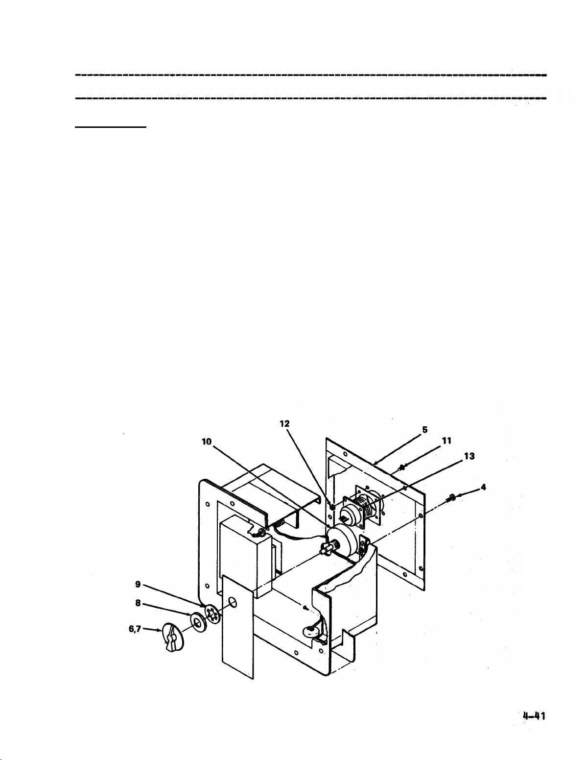
Rotary Switch
9.
10. Control Box
Wiring Harness
ACTION
Attach wires to terminal numbers 11,12 and 13.
a.
Align rotary switch (10) with hole in control box.
b.
Secure rotary switch to control box with
c.
REMARKS
star washer (9) and retaining nut (8).
Attach rotary switch knob to rotary switch.
d.
Secure rotary switch knob (7) to
e.
tightening two set screws (6) on
rotary switch by
rotary switch
knob .
Align control box wiring harness
a.
(13) with control
box back panel (5).
b.
Secure control box wiring harness to control box
back panel with four screws (11) and four
screws (12).
4-41
Page 76

TM5-4120-375-14
CONTROL BOX (CONT.)
LOCATION/ITEM
ACTION
REMARKS
--------------------------------------------------------------------------------
INSTALLATION
110 Control Box
a. Align control box (3) with holes in frame.
b. Secure control box with four screws (2)
and four screws (l).
4-42
Page 77

4-17.
TM5-4120-375-14
4-43
Page 78

TM5-4120-375-14
EVAPORATOR FAN GUARD (CONT.)
LOCATION/ITEM
INSPECTION
Evaporator Fan Guard
2.
INSTALLATION
Evaporator Fan Guard
3.
ACTION
REMARKS
a. Inspect for damage.
b. Repair or replace if damaged.
a. Align evaporator fan guard (2) with holes in
front panel (3) and frame.
b. Secure evaporator fan guard with four
screws (l).
4-44
Page 79

4-18.
TM5-4120-375-14
4-45
Page 80

TM5-4120-375-14
CONDENSER COIL GUARD (CONT.)
------------------------- ------------------------ -------------------------- ----LOCATION/ITEM
ACTION REMARKS
-------------------- -------------------- ------------------------- ---------------
INSPECTION
Condenser Coil Guard
2.
a. Inspect for damage.
b. Repair or replace if damaged.
INSTALLATION
Condenser Coil Guard
3.
a. Align condenser coil guard (3) with
holes in frame.
b. Secure condenser coil guard
with sixteen screws (1)
and two screws (2).
4-46
Page 81

4-19.
TM5-4120-375-14
4-47
Page 82

TM5-4120-375-14
AIR FILTERS (CONT.)
LOCATION/ITEM
INSPECTION AND SERVICE
Air Filters
2.
a. Spray filters with a water hose in opposite
b. Shake water from filter and allow to dry before
c. Inspect for
d. Replace if damaged.
Do not use oil on filters.
ACTION
REMARKS
direction of air flow (See arrow on filter frame)
installing.
damage.
CAUTION
NOTE
Note position arrow on filter frame when installing air filters.
Arrow must point toward evaporator coil.
4-48
Page 83

4-20 DAMPERS AND CONTROLS
THIS TASKS COVERS:
a. Removal
b. Inspection and repair
c. Installation
INITIAL SETUP
Test Equipment
None
Tools
TOOL KIT (SC 5180-90-C-N18)
References
None
Troubleshooting References
None
Special Environmental Conditions
None
General Safety Instructions
Turn air conditioner OFF before performing maintenance.
TM5-4120-375-14
LOCATION/ITEM
REMOVAL
Right Side Panel
1.
ACTION
a. Remove thirty-one screws (1) securing
right side panel (2) to frame.
REMARKS
4-49
Page 84

TM5-4120-375-14
DAMPERS AND CONTROLS (CONT.)
-------------------- ------------------------ ------------------------- ----------LOCATION/ITEM
ACTION
REMARKS
-------------------------------------------- ------------------------ -----------REMOVAL
Lifting Ring
2.
Covers
a.
Remove eight screws
(3)
and eight rubber washers (4)
securing lifting ring cover (5) to top panel (6)
and frame.
Remove lifting ring cover.
b.
Top Panel
39
a.
Remove twenty-three screws (7) and eight
screws (8) securing top panel (6) to frame.
b.
Remove top panel.
4.
Left Side Panel
a.
Loosen bottom center turnlock fastener (9)
in maintenance panel (10).
Remove twenty-seven screws (11) securing left
b.
side panel (12) to frame.
c.
Remove left side panel.
4-50
Page 85

DAMPERS AND CONTROL (CONT.)
TM5-4120-375-14
LOCATION/ITEM
REMOVAL
Left Return Air Damper
5.
ACTION
Loosen two screws (13) on mechanical post (14)
a.
REMARKS
securing control cable (15) to left return air
damper (16) and fresh air damper.
Remove two screws (17) securing left
b.
return air damper to frame.
Loosen screw (18) securing control cable housing (19)
c..
to control mechanism (20).
Pull control cable through control cable housing
d.
until it clears mechanical post on left return air
damper.
Remove left return air damper.
e.
Page 86

TM5-4120-375-14
DAMPERS AND CONTROLS (CONT.)
--------------------------------------------- ---------------------------- ------LOCATION/ITEM
ACTION
REMARKS
-------- --------------------------------- ----------------------------- ---------REMOVAL
Left Fresh Air Damper
6.
and Screen
a.
Loosen screws (21) on mechanical post (22) securing
control cable (23) to left return air damper and
fresh air damper (24).
b.
Pull control cable through control cable housing
until it clears mechanical post on left return air
damper.
c.
Remove four screws (25) and four nuts (26)
securing left fresh air damper (24) and
screen to frame.
Remove fresh air damper and screen.
d.
4-52
Page 87

DAMPERS AND CONTROLS (CONT.)
TM5-4120-375-14
LOCATION/ITEM
REMOVAL
ACTION
a.
Loosen screws (27) on mechanical post (28) securing
REMARKS
control cable (29) to left return air damper (30) and
fresh air damper (31).
b.
Loosen set screw (33) on control cable knob (34).
C..
Remove control cable knob.
d.
Remove retaining nut (35) and
control cable (37) to damper
e.
Remove one screw (39) and one look nut (40)
star washer (36) securing
control box (38).
scouring clamp (41) to frame,
f.
Remove clamp (42) from control cable housing
(43).
Slide control cable and housing out of unit.
Change 1
4-53
Page 88

TM5-4120-375-14
DAMPERS AND CONTROLS (CONT.)
LOCATION/ITEM
REMOVAL
8.
Damper Box
ACTION
a.
Remove four screws (47) and four screws (48)
securing control box
b.
Disconnect electrical connector (P-6) from back of
(49) to
frame and front panel.
REMARKS
control box.
c.
Remove control box.
d.
Remove thirty-four screws (50) and two screws
(51)
securing front panel
e.
Remove front panel.
(52)
to frame.
4-54
f. Remove two screws (54) securing damper box (55)
to frame.
g. Remove
Page 89

a.
b.
c.
d.
TM5-4120-375-14
e.
4-55
Page 90

TM5-4120-375-14
DAMPERS AND CONTROLS (CONT)
____________________________________________ _________________________
LOCATION/ITEM
ACTION REMARKS
_______________________________________________________________________________
REMOVAL
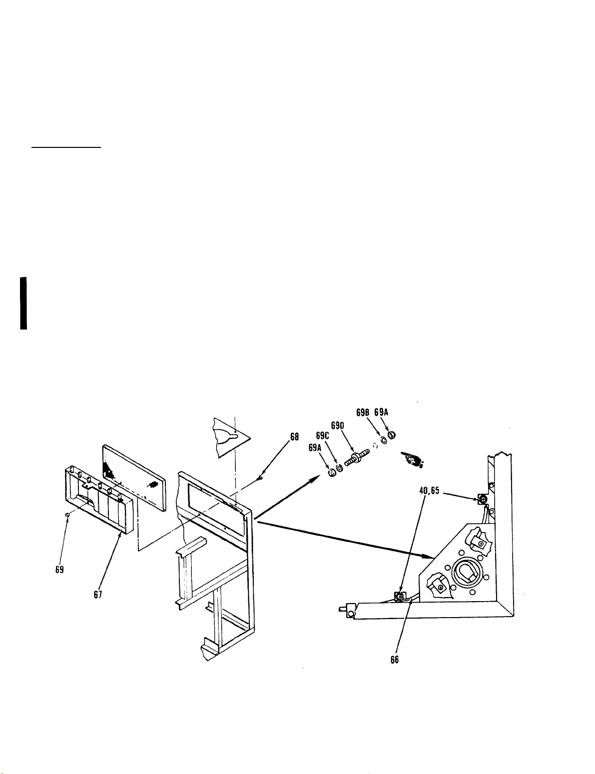
10. Right Fresh Air
Damper and Screen a.
Loosen screws (40) on mechanical post (65) securing
control cable (66) to right return air damper and
fresh air damper (67).
b.
Pull control cable through control cable housing
until it clears mechanical post on right return air
damper.
c.
Remove four screws (68) and four nuts (69)
securing right fresh air damper and
screen to frame.
Remove two lock nuts (69A), lock washer (69B),
d.
flat washer (69C), and grounding stud (69D).
Remove fresh air damper and screen.
e.
4-56
Change 1
Page 91

TM5-4120-375-14
Change 14-57
Page 92

TM5-4120-375-14
DAMPERS AND CONTROLS (CONT.)
LOCATION/ITEM
INSPECTION AND REPAIR
12. Damper Control and Cable
a. Inspect for freedom, of movement, lubricate if
b. Tighten loose mountings.
c. Replace defective controls.
13. Damper
a. Inspect for freedom of movement.
b. Inspect for damage.
c. Straighten bent louver blades.
d. Inspect for damaged gaskets.
e. Replace damaged gasket material and secure
ACTION
REMARKS
required (Table D-1, Item 17).
gasket with adhesive (Table D-1, Item 2).
f. Replace damaged damper.
4-58
Page 93

TM5-4120-375-14
DAMPERS AND
LOCATION/ITEM
CONTROLS (CONT.)
ACTION
NOTE
c.
Secure control cable housing (88) to frame with
one screw (80) and one locknut (81) and one clamp
(82).
REMARKS
d.
Align control cable (73) with damper box.
damper
control box
and star washer (77).
f.
Attach control cable knob to
Tighten set screw on control
g.
h.
Tighten screws (71).
control cable (73).
cable knob.
Change 1
4-59
Page 94
TM5-4120-375-14
Change 1
DAMPERS AND CONTROLS (CONT.)
--------------------------------------------------------------------------LOCATION/ITEM
ACTION REMARKS
------------------------------------------------------------------------------------------
INSTALLATION
15. Right Fresh
and Screen
Air Damper
a. Align right fresh air damper (67) and
b.
c.
d.
screen to frame.
Secure right fresh air damper and
screen to frame with four screws (68)
and four locknuts (69).
Install grounding stud (69D), flat washer (69C),
lock washer (69B), and two lock nuts (69A).
Secure control cable (66) to right fresh air
damper with mechanical post (65) and
tighten screw (40).
4-60
Page 95

DAMPERS AND CONTROLS (CONT.)
TM5-4120-375-14
LOCATION/ITEM
INSTALLATION
16. Right Return Air Damper
a. Align right return air damper (59) to frame.
b. Secure right return air damper to frame
c. Slide control cable (58) into unit insuring that
d.
ACTION
REMARKS
with two screws (60).
cable passes through mechanical post (57) on
right return air damper.
Secure control cable to right return air damper
with mechanical post and tighten screw (40).
4-61
Page 96

TM5-4120-375-14
DAMPERS AND CONTROLS (CONT.)
LOCATION/ITEM
INSTALLATION
17.
Damper Box
ACTION
a.
Align damper box (55) with holes in frame.
b.
Secure damper box to frame with two screws (54).
c.
Align front panel (53) with holes in frame.
Secure front panel to frame with thirty–four
d.
REMARKS
screws (50) and two screws (51).
e.
Connect electrical connector (P-6).
f.
Align control box (49) with holes in front panel
and frame.
Secure control box to front panel and frame with
g.
4-62
Page 97

TM5-4120-375-14
LOCATION/ITEM
INSTALLATION
ACTION
NOTE
b.
c.
d.
Align control cable with damper box (38).
REMARKS
32
Secure control cable (29) to damper control box
e.
with retaining nut (35) and star
f.
Attach control cable knob (34) to control cable
washer
(36).
(29) .
Tighten set screw (33) on control cable knob.
Tighten screws (27).
Change 1
4-63
Page 98

TM5-4120-375-14
DAMPERS AND CONTROLS (CONT.)
-------------------------------------------------------------------------------LOCATION/ITEM
ACTION
REMARKS
—----- --------------------------------------------------------------------------
INSTALLATION
19.
Left Fresh Air Damper
and Screen
a. Align left fresh air damper (24) and
screen to frame.
b.
Secure left fresh air damper and
screen to frame with four screws (25)
and four locknuts (26).
c. Secure control cable (23) to left fresh air
damper with mechanical post
screw
(21)
on mechanical post.
(22) and tighten
4-64
Page 99

DAMPERS AND CONTROL (CONT.)
TM5-4120-375-14
LOCATION/ITEM ACTION
20. Left Return Air Damper
a.
Align left return air damper (16) to frame.
b.
Secure left side return air damper to frame
with two screws (17).
Slide control cable
cable passes through ❑ echanical post (14) on
left return air damper and fresh air damper.
Secure control cable to left return air damper
d.
with mechanical post and tighten screw
mechanical post (14).
e.
Align control cable housing (19) with control
mechanism (20).
f.
Secure control cable housing to control mechanism
with one screw (18).
REMARKS
(15)
into unit insuring that
(13) on
4-65
Page 100

TM5-4120-375-14
DAMPERS AND CONTROLS (CONT.)
LOCATION/ITEM
ACTION
REMARKS
------------------------ --------------------- --------------------------- -------INSTALLATION
21. Left Side Panel
Align holes in left side panel
a.
(12) and maintenance
panel (10) with holes in frame.
Secure left side panel with twenty-seven
b.
screws (11).
Tighten bottom center turnlock fastener
c.
(9)
on maintenance panel.
4-66
 Loading...