

Page 1

TELEPHONE MAN OF AMERICA
Earning Your Business Every Step of the Way!
Specializing in Telecom Equipment of all Brands, Carrier Services, Technician Services, Maintenance
Agreements & Purchasing Excess Telecom Equipment!
I will always do my best to match or beat any competitors bid!
| Local: 863-614-1900| Toll Free: 866-770-4930| Fax: 888-782-3072|
Email: telephoneman@telephonemanofamerica.com |
URL: www.TelephonemanOfAmerica.com| URL: www.shop.telephonemanofamerica.com |
TalkSwitch VoIP
Page 2

The owner friendly™ phone system for small business
Start Guide
Release 6.12
Page 3

E V E R Y C A L L CO U N T S 1
INTRODUCTION
About this guide
This guide describes the steps required to do basic installation and configuration of
your TalkSwitch® telephone system. Once you have completed these steps, your
system can be further customized for your needs. For complete management details,
refer to the TalkSwitch User Guide.
This guide is intended for use with TalkSwitch VS models.
Where to go for further information
You can find additional documentation:
• Within the TalkSwitch management software by clicking the Help icons.
• On the TalkSwitch management software CD.
• By choosing Start > Programs > TalkSwitch 6.12 > Documentation once the
software is installed.
• In the support section at http://global.talkswitch.com.
Documentation
In addition to this guide, the following documentation is available:
• The TalkSwitch User Guide provides complete information about the
TalkSwitch system.
• The VoIP Network Configuration Guide describes setting TalkSwitch up for VoIP
(voice over IP) operation.
• Adding IP Phones to TalkSwitch describes configuring IP extensions.
• TalkSwitch telephone guides show how to use TalkSwitch phones.
• Help built into the TalkSwitch management software describes each window.
Contacting Technical Support
If you encounter difficulties with the installation or management of your
TalkSwitch system, consult the documentation. If you still have questions:
• Contact your authorized TalkSwitch reseller.
• If you purchased directly from TalkSwitch, e-mail support@talkswitch.com,
providing your company name and TalkSwitch product information.
Page 4

2 T A L K S W I TC H S T A R T G U I D E
GETTING STARTED
Checking package contents
Each package has the following, and may include region-specific materials:
• TalkSwitch unit
• TalkSwitch management software CD
• 120V AC adapter, or 230V AC adapter and AC
power cord
• RJ-11 telephone cables for each telephone line
• RJ-45 Ethernet cable
• Quick Reference Cards for each extension
• Wall mounting template, screws and anchors
for optional wall-mounting of your
TalkSwitch unit
• TalkSwitch Start Guide
• VoIP Network Configuration Guide (VoIP-enabled
TalkSwitch units only)
Recommended system specifications
You will need a PC to configure your TalkSwitch system. It should have:
• Windows Vista (32-bit), XP or 2000 operating system (fully updated)
• 220 MB free hard disk space (only 100 MB necessary if Java Runtime
Environment (JRE) is already available)
• 1 GHz CPU
• 1 GB RAM (Vista) or 512 MB RAM (XP or 2000)
• 1024 x 768 video resolution
Network equipment: If your system includes multiple TalkSwitch units, you will
need an Ethernet switch. If you plan on using VoIP or configuring your system
remotely, you will need an Ethernet switch (or router with an integrated switch)
and a broadband Internet connection.
Checking telephone wiring
TalkSwitch systems don’t require telephone wiring beyond the standard
infrastructure in most commercial and residential buildings. If your premises
require additional wiring for extensions, consult an authorized TalkSwitch reseller
in your area.
Caution! Lightning and electrical surges can damage the TalkSwitch unit. We recommend
using surge protection equipment on all external telephone and power lines connected to
this device.
Page 5

E V E R Y C A L L CO U N T S 3
STEP 1 — INSTALL THE TALKSWITCH MANAGEMENT SOFTWARE
1. Ensure you have Administrator privileges on your Windows Vista (32-bit), XP or
2000 system.
2. Turn your computer on and insert the CD into the CD-ROM drive.
3. The Install main window will appear within 20 seconds. Click INSTALL and follow
the instructions.
If the installation program does not automatically start (for example, if Autorun is
disabled on your PC):
1. From the desktop, double-click the My Computer icon.
2. Double-click on the CD drive labeled TalkSwitch.
3. Double-click on startscreen.exe located in the Start folder.
4. Click INSTALL and follow the instructions.
Page 6

4 T A L K S W I TC H S T A R T G U I D E
STEP 2 — CONNECT THE TALKSWITCH UNIT TO YOUR PC
OR NETWORK
The TalkSwitch unit can be set up anywhere in the vicinity of your telephone
lines and computer. Connect the TalkSwitch unit to your PC using a LAN (local
area network) or USB connection.
If you’re installing a TalkSwitch system with multiple units, or you’re adding a
TalkSwitch unit to an existing system, refer to Step 10 — Networking TalkSwitch
units on page 14.
Connecting to a LAN
Connect one end of the provided RJ-45 Ethernet cable to the LAN port at the back
of the TalkSwitch unit and the other end directly to your Ethernet switch. Ensure
your computer is connected to the same switch.
Connecting via USB
Using a USB A-to-B cable, connect the B end to the USB port at the back of the
TalkSwitch unit, and the A end to the USB port of your PC.
Powering up the TalkSwitch unit
1. Connect the provided AC adapter to the power port at the back of the
TalkSwitch unit and plug the adapter into a surge-protected power outlet.
Caution! Never use an AC adapter other than the one provided with the
TalkSwitch unit.
2. Press the Power button on the front of the unit. The lights on the front panel
will flash for a few moments during boot-up, then stop. The Data light will
remain lit, indicating the TalkSwitch unit is on.
USB
Power
LAN
Data
Power
Page 7
E V E R Y C A L L CO U N T S 5
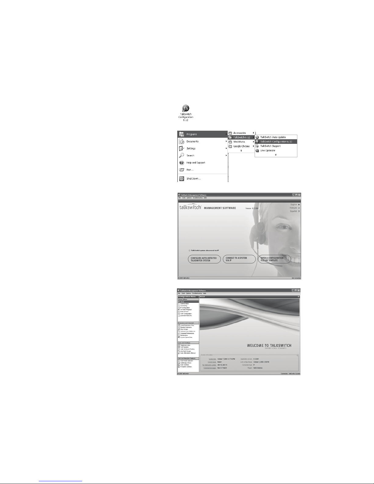
STEP 3 — OPEN THE TALKSWITCH MANAGEMENT SOFTWARE
1. Double-click the TalkSwitch
Configuration 6.12 icon on
your desktop.
You can also click Start > Programs >
TalkSwitch 6.12 > TalkSwitch
Configuration 6.12.
The TalkSwitch Management Software
window appears, and the software
attempts to detect your TalkSwitch unit.
2. Select your language. You can select
English, Français or Español.
3. Once the software detects your
TalkSwitch unit, click Configure
Auto-Detected TalkSwitch System.
The About page appears.
If the software was unable to detect your
TalkSwitch unit, check that all your wires
and plugs are securely connected, and
then click Retry Auto-Discovery. The
About page appears.
If auto-detection does not work, connect
an analog phone to the TalkSwitch unit,
and then dial *56. The TalkSwitch unit
will provide its IP address. Click Connect
to a Different System, and then enter
the IP address. The About page appears.
If you want to open or create a
configuration file, click Open a
Configuration File or Template.
For more information, refer to File menu
in Chapter 2 of the TalkSwitch User Guide.
Page 8

6 T A L K S W I TC H S T A R T G U I D E
STEP 4 — SET THE PASSWORD AND REGION
1. Select the Administration page.
2. Optionally enter the System name. This should be the company name, or a
shortened form suitable for use as caller ID during VoIP calls.
3. Enter a System password. It has to be a 4- to 8-digit numeric password, so you
can also enter it on a touchtone phone. The system password allows access to
the configuration.
4. If the Region Selection area is present, select the country where your
TalkSwitch unit will operate.
5. Optionally load additional languages for system prompts, and set the default
language for system prompts heard by callers and users.
6. Optionally set up how the system will route the call if the user dials 0 (9 in
some countries). For example, the user can dial 0 to reach the receptionist at
extension 114.
CAUTION: Use a system password, otherwise the system will be vulnerable to
configuration changes, misuse and/or lock-out by callers or users. If the router
has port 9393 mapped to the TalkSwitch unit for remote configuration, the
system will also be vulnerable to anyone on the Internet.
Change the system password frequently to prevent unauthorized users from
making calls or changing the configuration.
!
"
#
$
Page 9

E V E R Y C A L L CO U N T S 7
STEP 5 — CONFIGURE AN AUTO ATTENDANT
An auto attendant answers incoming calls and plays a greeting that offers
options. For example, an auto attendant can instruct callers to dial extensions, or
dial 0 to reach the receptionist. It could also tell them how to:
• Hear prompts in a different language.
• Listen to an announcement with store hours and location.
• Access the dial-by-name directory.
• Reach the next available agent in the sales group or support group.
• Leave a voicemail.
If you don’t want to set up an auto attendant now, you can proceed to Step 6 —
Configure telephone lines on page 8.
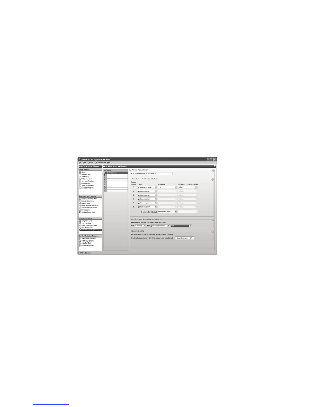
1. Select Auto Attendants (Menus).
2. Click 1 to configure auto attendant 1
(default selection).
3. Select the Activate Auto Attendant 1
check box, and then give your auto
attendant a descriptive name (e.g.
Business Hours).
4. In the drop-down lists next to Caller
presses 0: (‘9’ in some countries), set
Action to go to local extension, and
Resource to 114.
5. Repeat step 4 for other auto
attendant options (e.g. dial 1
for sales).
6. Configure the auto attendant to transfer the call to the receptionist if the
caller doesn’t respond. This can occur if the caller doesn’t have a touchtone
phone, or doesn’t understand the greeting. Select 5 seconds, go to local
extension, and 114.
7. After phones are connected to the TalkSwitch unit, set up your auto
attendant greeting as described in Step 9 — Auto attendant and voicemail
greetings on page 12.
For complete details and options, such as automatic fax detection, refer to Auto
Attendants (Menus) in Chapter 2 of the TalkSwitch User Guide.
!
"
%
#
Page 10

8 T A L K S W I TC H S T A R T G U I D E
STEP 6 — CONFIGURE TELEPHONE LINES
Set up your telephone lines to route incoming calls to an auto attendant,
extensions or a voice mailbox.
1. Select Telephone Lines.
2. Click Unit 1, Line 1 to set up line 1.
3. Select the Activate Line check box.
4. Select the Mode 1 tab in the Main Number tab.
A mode is a period of time with particular call handling. For example, a call
can ring extensions during Mode 1 (business hours), and go to voicemail
during Mode 2 (evenings and weekends).
5. Set up call handling for the telephone line, as described below.
Playing the auto attendant immediately
The auto attendant can immediately answer all incoming calls on this
telephone line.
1. As illustrated above, select go to auto attendant, 1 (or the name of auto
attendant 1), and immediately.
"
%
$
!
Page 11

E V E R Y C A L L CO U N T S 9
Ringing extensions before playing the auto attendant
The system can ring selected extensions, and then play the auto attendant if no
one answers.
1. Select go to auto attendant, 1 (or the name of auto attendant 1), and the
number of rings (e.g. after 3 rings).
2. Click Edit to select which extensions will ring, and to set up their ring
sequence. By default all extensions will ring at the first ring.
Sending calls to voicemail
The system can ring selected extensions, and then send the call to voicemail if no
one answers.
1. Select go to voicemail, the voice mailbox number, and the number of rings
(e.g. after 3 rings).
2. Click Edit to select which extensions will ring, and to set up their ring
sequence. By default all extensions will ring at the first ring.
STEP 7 — SAVE SETTINGS
1. Choose File > Save. The software transfers the configuration settings to the
TalkSwitch system, and backs up the settings to a file.
Page 12

1 0 T A L K S W I TC H S T A R T G U I D E
STEP 8 — CONNECT TELEPHONE LINES AND EXTENSIONS
Caution! Lightning and electrical surges can damage the TalkSwitch unit. We recommend
using surge protection equipment on all external telephone and power lines connected to
this device.
Connecting a single-line telephone line
A single-line wall phone jack has one telephone line.
Use the provided RJ-11 telephone cables to connect telephone lines to the
TalkSwitch unit. These cables have a 2-wire connector for connection to a
single-line wall phone jack.
1. Connect one end of the provided RJ-11 telephone
cable to the wall phone jack of a telephone line, and
the other end to the L1 jack on the back of the
TalkSwitch unit.
2. If necessary, connect additional telephone lines to the
L2–L8 jacks.
Connecting a two-line telephone line
A two-line wall phone jack has two telephone lines.
TalkSwitch VS units require that each telephone line be
connected to a separate jack on the back of the
TalkSwitch unit.
Use two of the provided RJ-11 telephone cables and a
dual-to-two-single-line adapter to connect a pair of
telephone lines to the TalkSwitch unit.
1. Connect the dual-to-two-single-line adapter to the
wall phone jack.
2. Connect one end of the provided RJ-11 telephone
cable to the adapter, and the other end to the L1 jack
on the back of the TalkSwitch unit.
3. Connect one end of the second RJ-11 telephone cable
to the adapter, and the other end to the L2 jack.
4. If necessary, connect additional telephone lines to the
L3–L8 jacks.
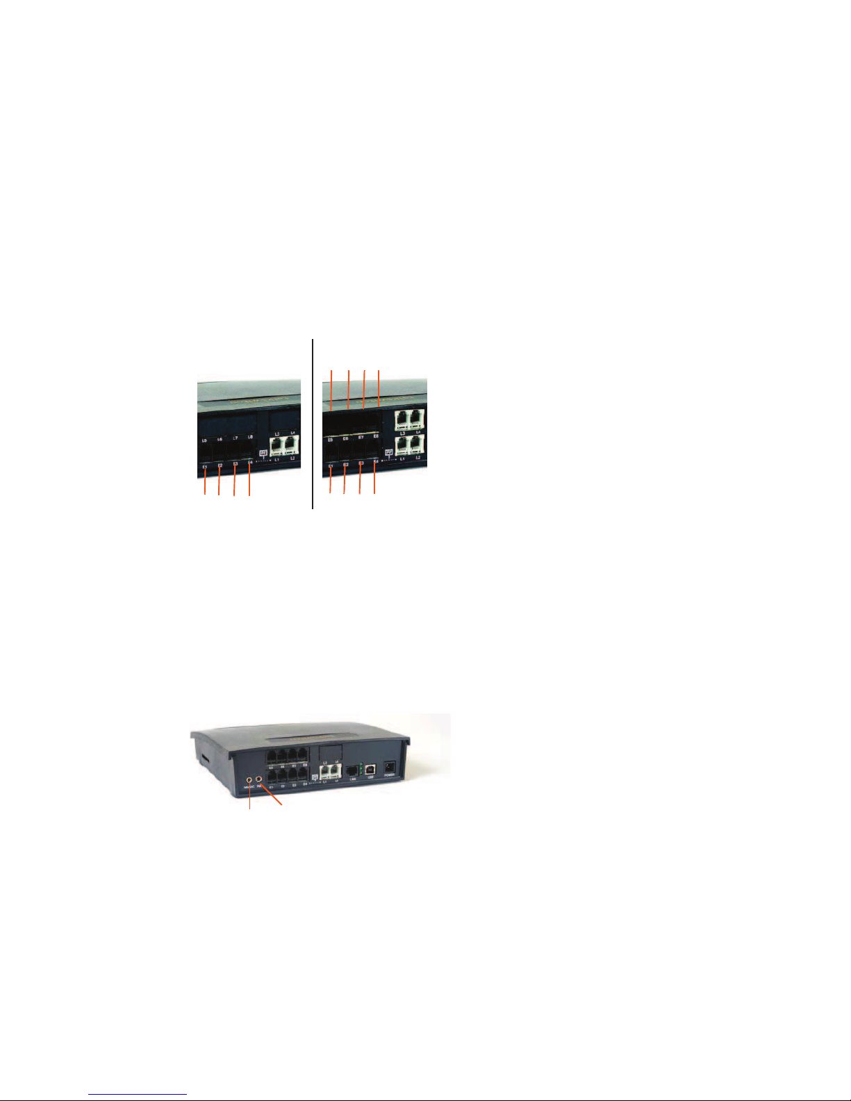
Eight-line unit
L1
L2
L3 L4L5
L6 L7 L8
2-wire connector
Two-line unit
L1
L2
Four-line unit
L3
L1
L2
L4
Page 13
E V E R Y C A L L CO U N T S 1 1
Connecting analog extensions and a fax machine to the TalkSwitch unit
Connect the cables from your analog phones to the E1–E8 jacks on the back of the
TalkSwitch unit. If your system has one TalkSwitch unit, the extension numbers
for these jacks are 111–118.
If you have a fax machine, the Auto Attendant (Menus) page allows you to set
its extension number (e.g. 118). Connect the fax machine to the associated jack
(e.g. E8).
Connecting an external audio source (optional)
You can add music on hold to your system from an external audio source or
internal music file.
Connect a 1/8" (3.5 mm) mono phono connector cable from an isolated external
audio source such as a CD player, tape player, or sound card to the MUSIC jack of
the TalkSwitch unit.
If your system has multiple TalkSwitch units, you will need to provide audio to
the MUSIC jack of each unit.
For complete details on configuring music on hold and for using internal music
files, refer to On-Hold/Ringback in Chapter 2 of the TalkSwitch User Guide.
Four-extension unit
Eight-extension unit
E1 E2 E3 E4 E1 E2 E3 E4
E5 E6 E7 E8
MUSIC
PA
Page 14

1 2 T A L K S W I TC H S T A R T G U I D E
Connecting to a PA system (optional)
You can connect the TalkSwitch unit to a PA amplifier. A user can then dial *0 to
make an overhead page. The PA jack can also be used for voicemail screening. The
TalkSwitch unit will play the call through the PA jack if a caller or user accesses a
voice mailbox.
Connect a 1/8" (3.5 mm) mono phono connector cable from the PA jack of the
TalkSwitch unit to the amplifier.
If your system has multiple TalkSwitch units, you will need to connect the PA jack
of each unit to the amplifier.
For complete details on configuring the PA jack, refer to PA Output in Chapter 2 of
the TalkSwitch User Guide.
STEP 9 — AUTO ATTENDANT AND VOICEMAIL GREETINGS
If you set up an auto attendant, as described in Step 5 — Configure an auto
attendant on page 7, you should record or load a greeting now.
If your system has multiple TalkSwitch units, the greeting will be automatically
copied to each unit.
What should an auto attendant say?
The auto attendant greeting should greet the caller and identify your company. It
should then explain the options you set up in Step 4. For example, if you set up
the auto attendant shown on the following page, the greeting could say:
“Welcome to ABC Company. If you know your party’s three-digit extension, please
dial it now. To reach the receptionist, dial 0 or stay on the line.”
Sample auto attendant greeting
The following sample auto attendant greeting is in C:\Program
Files\TalkSwitch\TalkSwitch Configuration 6.12\Greetings\Auto Attendant
Sample.wav.
“Welcome. If you know the three-digit extension of the person you wish to reach,
please dial it now. Otherwise press ‘0’ to reach the next available representative.
Thank you.”
Page 15
E V E R Y C A L L CO U N T S 1 3
Recording an auto attendant greeting
To record an auto attendant greeting for auto attendant 1:
1. Enter command mode either by pressing # from an analog extension, or *55#
from a TalkSwitch IP phone, followed by the system password, then #. (Other
brands may use *55 SEND or *55 DIAL.)
2. Dial 41#, and then follow the prompts to record your message.
3. When your greeting is complete, press # to end the recording.
Loading a recorded auto attendant greeting
You can load a professionally recorded greeting. The file must be an 8 kHz, 8-bit,
mono, µ-law .wav file.
1. Select Auto Attendant (Menus).
2. Click the Load Greeting button. The Select Wav File window appears.
3. Browse to the .wav file.
Setting up extensions
Each user can set up their own extension. The user should:
1. Pick up their phone, and then dial **#.
2. Follow the prompts to record a greeting, change personal options, and record
their name for the dial-by-name directory.
For complete details, refer to Using the voicemail system in Chapter 3 of the
TalkSwitch User Guide.
!
Page 16

1 4 T A L K S W I TC H S T A R T G U I D E
STEP 10 — NETWORKING TALKSWITCH UNITS
TalkSwitch units and IP phones can be networked over a LAN to increase the
number of lines and extensions in your system.
Note: TalkSwitch unit enclosures are not designed for stacking. We recommend
wall-mounting the units in a horizontal row to maximize airflow and
prevent overheating.
Connecting TalkSwitch units
1. Use RJ-45 Ethernet cables to connect up to four TalkSwitch units to your
Ethernet switch.
Powering up all TalkSwitch units
1. Connect the provided AC adapters to the power ports of each TalkSwitch unit
and plug each adapter into a surge-protected power outlet.
2. Turn on the TalkSwitch units by pressing the Power button on the front of
each unit.
Setting TalkSwitch unit ID numbers
Each TalkSwitch unit is pre-programmed with unit ID 1. When you plug multiple
units in for the first time or add one to an existing network, the newly added
units will automatically choose an available unit ID number. To confirm the unit
ID assigned:
1. Connect a phone to the TalkSwitch unit for which you would like to check the
unit ID.
2. Lift the phone handset.
3. Dial *55, enter the admin. password it assigned, then dial 00#.
Configuring networked units
Now that you have connected your TalkSwitch units and checked the unit ID
numbers, you can configure the new unit(s). Return to Step 3 — Open the
TalkSwitch management software on page 5 and follow the subsequent steps to
complete the configuration of your expanded TalkSwitch system.
Page 17

E V E R Y C A L L CO U N T S 1 5
Extension and voice mailbox numbers
Each local extension, remote extension and voice mailbox has a unique number.
The first digit indicates the type of extension or voice mailbox. The second digit
identifies the unit. The third digit indicates the extension or voice mailbox.
IP extensions
See Adding IP Phones to TalkSwitch for instructions on how to configure IP
extensions. If you are setting up external IP extensions, see the VoIP Network
Configuration Guide as well.
Extension and voice mailbox numbers for networked units
Unit ID 1 Unit ID 2 Unit ID 3 Unit ID 4
Local extensions 111–118
151–158
121–128
161–168
131–138
171–178
141–148
181–188
Remote extensions 210–219 220–229 230–239 240–249
Local voice mailboxes 111–118
151–158
121–128
161–168
131–138
171–178
141–148
181–188
Remote voice mailboxes 210–219 220–229 230–239 240–249
General voice mailboxes 410–419 420–429 430–439 440–449
125
Local extension
TalkSwitch unit ID 2
Extension 5
Page 18

1 6 T A L K S W I TC H S T A R T G U I D E
SETUP COMPLETE
Congratulations!
Your TalkSwitch system is ready to accept incoming calls. Put a Quick Reference
Card next to each extension phone to help employees become familiar with the
TalkSwitch features.
What next
Refer to the built-in Help files or the TalkSwitch User Guide for instructions on
how to set up:
• Modes for handling incoming calls after hours and during holidays.
• Local extensions for placing and receiving calls within the office.
• Remote extensions for receiving calls outside the office.
• Ring groups so callers can reach the first person available in the sales, support
or other team.
• Call cascades to automatically transfer unanswered calls between local
extensions, remote extensions and ring groups.
• Caller ID based routing to automatically transfer calls based on who’s calling.
• Line hunt groups to control access to outbound telephone lines.
• System speed dials to quickly call clients from any extension.
• E-mail to notify users when they have voicemail.
• Auto route selection, call bridge and call back to reduce costs.
• Remote management for using the TalkSwitch system via the Internet.
© 2009 TalkSwitch, a division of Centrepoint Technologies Inc. All Rights Reserved.
TalkSwitch®, the TalkSwitch logo, Concero®, answers with intelligence®, owner friendly™,
seller friendly™, vendor friendly™ and channel friendly™ are registered trademarks or
trademarks of Centrepoint Technologies Inc.
CT.TS005.002509 (October 2009)
We trust your TalkSwitch telephone system will provide exceptional features,
performance and value to your business. Should you have any further questions,
please contact your authorized TalkSwitch reseller. If you purchased directly
from TalkSwitch, visit the support section at http://global.talkswitch.com.
We welcome your feedback, comments and suggestions. Please e-mail us at
info@talkswitch.com or write us at TalkSwitch, 1545 Carling Avenue,
Suite 510, Ottawa, ON Canada K1Z 8P9.
Thank you for choosing TalkSwitch.
 Loading...