

Page 1

CONNECTING PHONES, FAXS & DEVICES TO TALKSWITCH
WHAT WILL MY PHONE SYSTEM DO?
Default Equipment Settings:
Simply connect the Talkswitch to your phone system (as shown below).
Your phone system will do the following:
· An incoming call on any line will ring all local extensions.
· A receptionist can manually transfer calls to local extensions or
voicemail.
· Every local extension gets a voicemail box.
· Extension 114 (E4) works during a power failure.
Additional Capabilities can be added by installing the TalkSwitch Software.
SUGGESTED CONFIGURATION
Connections from the TalkSwitch to all your telephone devices and computer. you
need not add all of the phones. The fax machine should be put into local extension
‘E8’ for a TalkSwitch 48-CA and 48-CVA, or ‘E3’ for the TalkSwitch 24-CA.
WWW.TALKSWITCH.COM 1
TALKSWITCH QUICK GUIDE
CONNECTING PHONES,
FAXES & DEVICES TO
TALKSWITCH
CT.TS005.504.EN - 03
LAN
Music-on-Hold
3.5mm jack
P.A.
3.5mm jack
‘E1’ jack to
Extension 111
‘E2’ jack to
Extension 112
‘E3’ jack to
Extension 113
‘E4’ jack to
Extension 114
‘E5’ jack to
Extension 115
‘E6’ jack to
Extension 116
‘E7’ jack to
Extension 117
‘E8’ jack to
Extension 118
Incoming Phone
Lines
L1 to L4
Remote Extensions 211, 212 ... 218
Serial connection to PC
computer via an RS232
serial cable
USB connection to PC
computer via a USB cable
AC connection to poweroutlet
TalkSwitch Back Panel
TalkSwitch 48-CA/ 48-CVA shown here.
Model Differences:
TalkSwitch 24-CA
2 Lines In (L1/L2 and L2 only)
4 Local Extensions (E1 - E4 only)
No Lan Connection
TalkSwitch 48-CAand -CVA
4 Lines In (as shown)
8 Local Extensions (as shown)
LAN Connection
(receptionist)
(fax)
*Memory card slot on side.
Page 2

?
CONNECTING DEVICES
Move the TalkSwitch to a location where it can be attached to incoming telephone
lines and your telephone devices.
Connect phone devices as shown in the “Suggested Configuration” on the previous
page; this corresponds to the TalkSwitch default settings. TalkSwitch does NOT need to
remain connected to the computer - only when changing configuration settings.
Here are a few things to consider when placing your TalkSwitch:
Incoming Phone Lines
Choose a convenient wall jack for you to attach to your TalkSwitch. Then connect
your telephone lines in the following manner:
- Connect the first incoming phone line to L1/L2.
- Connect the second to L2.
TalkSwitch 48-CA and 48CVA users can then connect remaining lines to
L3/L4 and L4. If you
have 2 lines out of 1
phone jack, you can
plug it into the L1/L2,
and L3/L4 jacks.
Local Extensions
Plug each internal telephone into lines E1
through E8 consecutively.
Make sure the fax line has been put into E8 or E3.
It is a good idea to connect E4 to a phone, as this is the only extension that will
work during a power failure.
Location
Check out the location of electrical wall outlets and telephone jacks in the room. Place
TalkSwitch close enough to these items using your AC Adapter and telephone cords.
Music on Hold
Connect the 1/8" (3.5mm) phono connector from the music jack to an audio source such
as CD player, radio, tape player, or computer sound card.
Need Help Wiring?
Need help wiring your house or small office? Not sure where all the jacks are, or what
colors of wires you should use? Need to do some rewiring?
Make the most out of your phone system with our “Home/Office Wiring” Quick Guide.
WWW.TALKSWITCH.COM 2
CONNECTING PHONES, FAXES AND DEVICES TO TALKSWITCH
TalkSwitch
System
!
Page 3
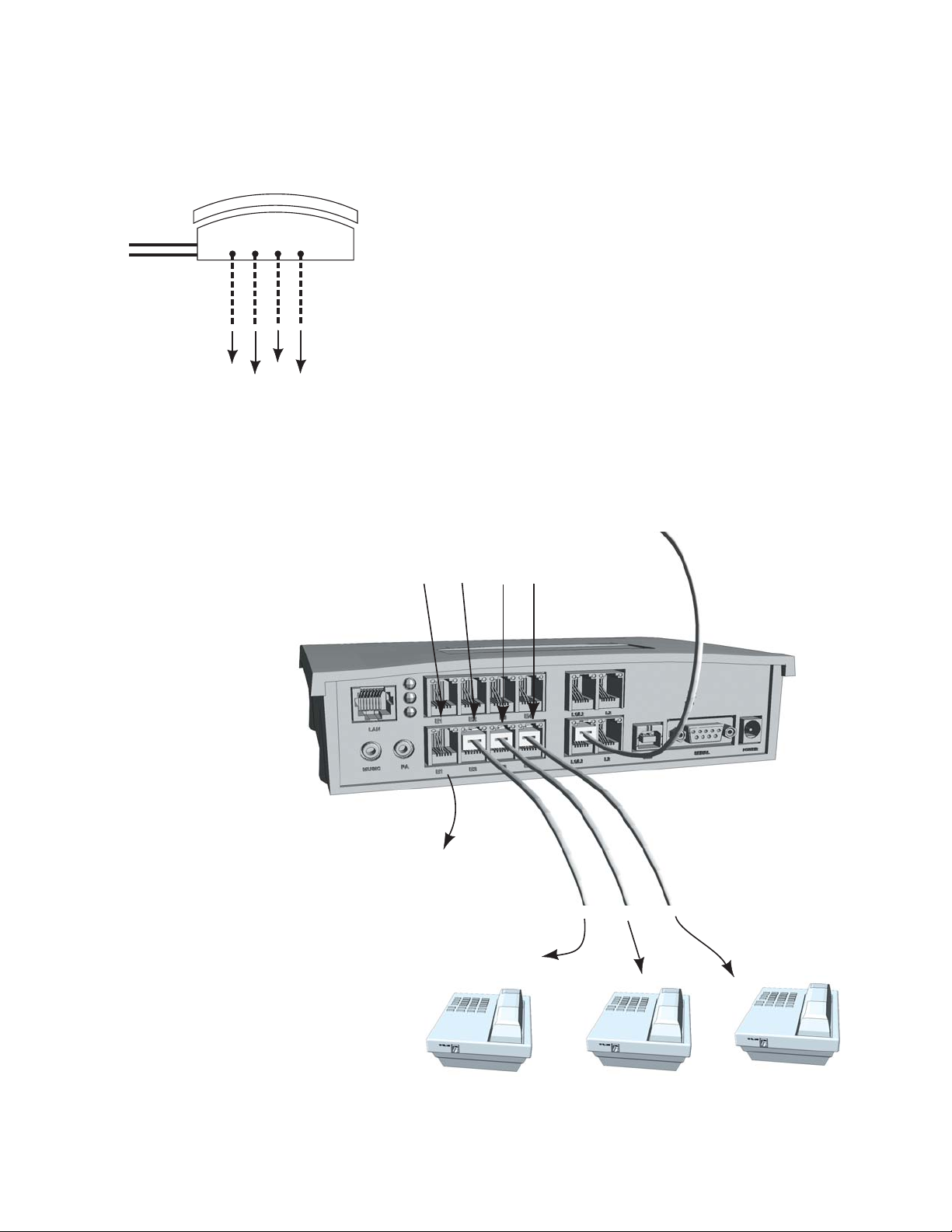
WIRING PHONES
Call Handling:
All incoming calls will be routed to the individual phones by TalkSwitch. All
call handling such as call forwarding, transferring, voicemail etc., is done by
TalkSwitch.
NOTE: Incoming lines are not directly connected to any of the local exten-
sions, instead the software determines which incoming lines are routed to
what local extensions.
By default all incoming lines ring all local extensions. How you change the
default software settings will depend upon the types of phones you use and
how you decide to wire them.
WWW.TALKSWITCH.COM 3
CONNECTING PHONES, FAXES AND DEVICES TO TALKSWITCH
E1 E2 E3 E4
TalkSwitch Jacks
Incoming
Phone Lines
To Phones
Extensions:
111
112
113
114
E1 E2 E3 E4
Extension 111
Phone not shown
From Phone Lines
RJ-11 cable to incoming phone lines
To Phones
RJ-11 cable to phone lines
TalkSwitch 48-CA and 48-CVA - Rear Panel
Use the following pages to
determine how to connect
single line, two line, and
multi-line phones.
Page 4
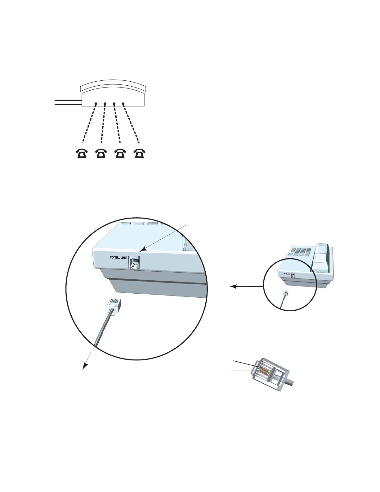
CONNECTING PHONES: SINGLE LINE PHONE
Call Handling:
This is the simplest set-up, where each phone is connected to a single
extension. A call transferred to extension 111 will ring the phone connected on TalkSwitch jack E1; similarly a call transferred to extension 112 will
ring the phone on jack E2, extension 113 will ring E3, etc.
All functionality including transferring calls, forwarding calls, and voicemail, is handled by TalkSwitch. Even the most basic of phones therefore,
once connected to TalkSwitch, will inherit the capabilities of TalkSwitch.
WWW.TALKSWITCH.COM 4
CONNECTING PHONES, FAXES AND DEVICES TO TALKSWITCH
"To Tel. Line"
Pin 2
Pin 1
Ext 111
To TalkSwitch Jack E1
Single Line RJ-11 Jack
Each phone is connected to a single line RJ-11 cable. The jacks at the end of the cables should have two pins, although a 2
line/ 4 pin cable will also work.
Incoming
Phone Lines
Extensions 111 112 113
TalkSwitch Jacks
E1 E2 E3 E4
114
Page 5

CONNECTING PHONES: TWO LINE PHONE - OPTION 1
Call Handling:
TalkSwitch extensions 111 and 112 are wired to a two line phone. When a call
is transferred to extension 111, line 1 on the phone will show as active; similarly calls on extension 112 will show line 2 as active.
Through the software, you may configure each incoming line to ring any given number
of extensions, including all extensions. However, be careful if incoming line 1 is configured to ring both extensions 111 and 112. An incoming call will ring both phone
lines at the same time. Instead configure incoming line 1 to ring extension 111, and
line 2 to ring extensions 112.
WWW.TALKSWITCH.COM 5
CONNECTING PHONES, FAXES AND DEVICES TO TALKSWITCH
E1 E2 E3 E4
TalkSwitch Jacks
Incoming
Phone Lines
Extensions 111 and 112
k
L1 OR L1/L2
L2
Each phone is connected to a single line RJ-11
cable. The jacks at the end of the cables should
have two pins as shown below..
Two line phones must have these two phone
jacks labeled “L1/L2” and “L2”. The jack
labeled “L1/L2” will have 4 pin connectors and
the “L2” jack will have 2 pin connectors.
To Tel. Line L1 or L1/L2
To Tel. Line L2
L1 OR L1/L2
L1 OR L1/L2
L2
L2
Ext 111
To Jack E1
Ext 112
To Jack E2
Pin 1
Pin 2
Single Line RJ-11 Jac
Page 6

CONNECTING PHONES: TWO LINE PHONE - OPTION 2
Call Handling:
TalkSwitch extensions 111 and 112 are wired to a two line phone using a line
splitter. When a call is transferred to extension 111, line 1 on the phone will
show as active; similarly calls on extension 112 will show line 2 as active.
Through the software, you may configure each incoming line to ring any given number
of extensions, including all extensions. However, be careful if incoming line 1 is configured to ring both extensions 111 and 112. An incoming call will ring both phone
lines at the same time. Instead configure incoming line 1 to ring extension 111, and
line 2 to ring extensions 112.
WWW.TALKSWITCH.COM 6
CONNECTING PHONES, FAXES AND DEVICES TO TALKSWITCH
E1 E2 E3 E4
TalkSwitch Jacks
Incoming
Phone Lines
Extensions 111 and 112
Line Splitter
Line Splitter
L1 and L2 are single line (2 pin) female
connectors that join to a two line (4 pin) male
connector. A4 pin female receptical will
indicate that you have a duplexer and not a
line splitter.
Connect the male end of the
line splitter into the telephone
jack labeled “L1/L2”
Each phone line is connected to the line splitter
via a single line RJ-11 cable. The jacks at the end
of the cables should have two pins.
To Tel. Line L1 or L1/L2
To Tel. Line L2
Ext 111
To Jack E1
Line Splitter
Ext 112
To Jack E2
Male (4 pin)
L1 (2 pin)
Single Line RJ-11 Jack
L2 (2 pin)
Page 7

CONNECTING PHONES: MULTI-LINE PHONES
Call Handling:
TalkSwitch extensions 111, 112, 113, and 114 are all wired to the four line
phone. When a call is transferred to extension 111, line 1 on the phone
will show as active; similarly calls on extension 112 will show line 2 as
active etc.
Through the software, you may configure each incoming line to ring any
given number of extensions, including all the extensions. However, be
careful if incoming line 1 is configured to ring extensions 111, 112, 113,
and 114. An incoming call will ring all four phone lines (lines 1 through 4)
at the same time. Instead configure incoming line 1 to ring extension 111,
line 2 to ring extension 112, etc.
WWW.TALKSWITCH.COM 7
CONNECTING PHONES, FAXES AND DEVICES TO TALKSWITCH
E1 E2 E3 E4
TalkSwitch Jacks
Incoming
Phone Lines
Extensions 111, 112, 113, & 114
4 Line Phone
Line Splitter
Line Splitter
Ext 112
To Jack E2
Ext 112
To Jack E2
Ext 113
To Jack E3
Ext 114
To Jack E4
Line Splitter
Connector
To Tel. Line L1/L2
To Tel. Line L3/L4
Male (4 pin)
L1 (2 pin)
L2 (2 pin)
RJ-11 Cord
2 line (4 wire) male to male connector
RJ-11 Coupler
2 line (4 pin) female to female connector
Line Splitter
L1 and L2 are single line (2 pin) female connectors
that join to a two line (4 pin) male connector. A 4
pin female receptical will indicate that you have a
duplexer and not a line splitter.
Page 8

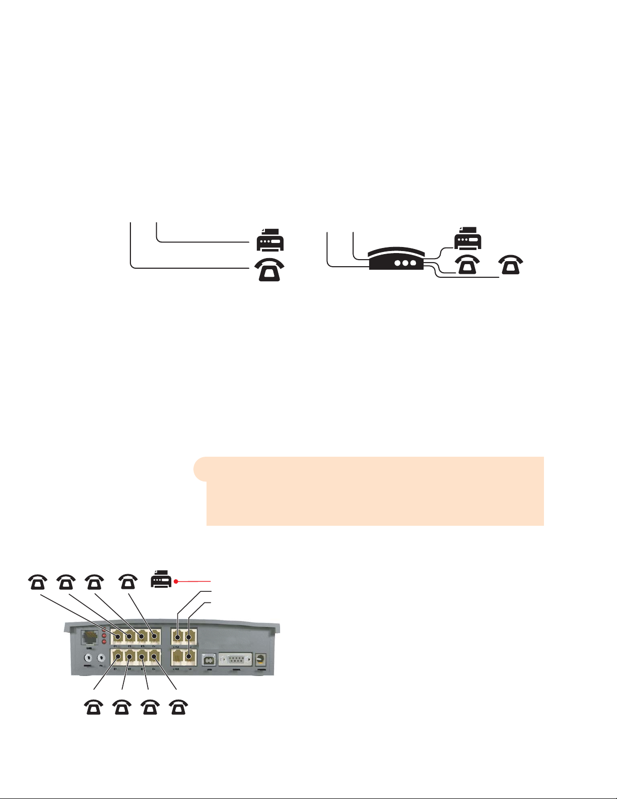
CONNECTING FAXES
1. Choose a Method to Handle Incoming Faxes
Only you can decide how you want to configure your office. Some solutions will be
suited to your needs, others won’t. Take a look at each option to decide what is best
for you.
Option 1 : Dedicated Fax Line
You may already have an incoming dedicated fax line. Simply connect this line to your
fax machine directly and the remaining incoming telephone lines to your TalkSwitch.
Incoming telephone lines will be handled by the TalkSwitch and your fax will work the
way it has always worked.
Advantages: easy to set up, and you don’t change the way your fax handles calls.
Disadvantages: The dedicated fax line can not be shared with the other phone devices,
i.e. you can not make an outbound voice call on your fax line. The dedicated fax line
costs money, and may not be used as often.
Option 2: Distinctive Ring
Distinctive ring is a service provided by your phone company where a second phone
number is added to the same physical telephone line. i.e you have two telephone
numbers that ring on the same line - each telephone number produces a different
style of ring on your phones. Here’s how the TalkSwitch would handle incoming calls.
Advantages: Does not require a 2nd physical line for faxes.
More telephone lines can be added as you grow, and you can keep the same fax
arrangement.
Disadvantages: You only have one line, and can therefore only handle one call at a
time.
You may have to purchase distinctive ring from your phone company.
WWW.TALKSWITCH.COM 8
CONNECTING PHONES, FAXES AND DEVICES TO TALKSWITCH
Before installing TalkSwitch, both phones and faxes are on
dedicated lines.
After installing TalkSwitch the fax machine remains on its own
dedicated line. All incoming telephone lines are shared bythe
remaining office phones.
A single telephone line with two assigned numbers, each number has a
different ring pattern. Based on the ring pattern you pick up the phone, or
let the fax answer the call.
After installing TalkSwitch, the TalkSwitch automatically routes faxes to the
fax machine, and callers to the phones.
Distinctive
Ring 2
Distinctive
Ring 1
Distinctive
Ring 2
Distinctive
Ring 1
Page 9
?
Option 3: Automatic Detection via the Auto Attendant
The Auto Attendant must answer all incoming calls with your pre-recorded message.
It will listen for a CNG tone to see if the call is an incoming fax or a human. If the
call is a fax, it is routed to the fax machine, otherwise the call is treated as though it
were a human. You must create an Auto Attendant to use this method.
Advantages: Calls are automatically handled for you, no distinctive ring, no listening to
ring patterns.
Incoming phone lines are shared between all phones and faxes making better use of
your resources.
Disadvantages: Older fax machines do not emit a CNG tone, therefore the auto
attendant can not detect them as an incoming fax.
If your auto attendant volume is set too high, or if your telephone lines are noisy, the
auto attendant may have difficulty detecting the incoming CNG tone, and therefore
not route the call to the fax machine.
Which Option Do You Prefer?
Option Complete This Step Only
Option 1 : Dedicated Fax Line Step 2
Option 2 : Distinctive Ring Step 3
Option 3 : Detection via Auto Attendant Step 4
2. DEDICATED FAX LINE
Connect the fax machine directly to the incoming fax line. The remaining incoming
lines can be connected to TalkSwitch via jacks L1 to L4.
The local phone extensions are connected to jacks E1
through E8.
Remember, TalkSwitch 24-CA units only have 2 incoming
lines and 4 local extensions, so incoming lines are connected to jacks L1 and L2, and local phone extensions to
E1 through E4.
WWW.TALKSWITCH.COM 9
CONNECTING PHONES, FAXES AND DEVICES TO TALKSWITCH
Before installing TalkSwitch, both phones and faxes are
on dedicated lines.
After installing TalkSwitch, all incoming calls are answered by the auto attendant.
The auto attendant then directs the call to the fax or local phone extensions.
TalkSwitch 48-CA and 48-CVA with dedicated fax line.
Fax Machine connected directly
to an incoming line.
Incoming Lines connected to
TalkSwitch to be shared among
internal extensions.
Page 10

3. DISTINCTIVE RING FAX DETECTION
3.1 Connect TalkSwitch to the PC, then Open the TalkSwitch Software
Connect TalkSwitch to your PC and open the TalkSwitch Configuration Software. For
details refer to the “TalkSwitch Installation and User Guide”.
3.2 Set Distinctive Ring Numbers
One of the incoming lines will have a distinctive ring number assigned to it. This
number will need to be recognized by TalkSwitch as an incoming fax line. Follow the
steps below.
3.3 Set Fax Detection on Distinctive Ring Number
Configure the fax detection as shown
WWW.TALKSWITCH.COM 10
CONNECTING PHONES, FAXES AND DEVICES TO TALKSWITCH
Step E
Step D
Step C
Step B
Step A
Choose “System Information” and then
“Telephone Lines” - See Arrows
2
1
Choose the Line number for the
incoming fax.
Activate the Line
Enter the Line telephone number. This is
the number people use
to call your office.
Enter the distinctive ring
number on this line.
This is the number people will call to get your
fax machine
STEP C
STEP B
Step A
Choose “System Information” and then
“Fax Information” - See Arrows
2
1
Enter the Distinctive Ring number for the incoming fax. This is the number people will
call to get your fax machine, and is the same asStep “E” above.
Enter the local extension
number for your fax. This
is the extension you will
plug your fax machine
into.
For TalkSwitch 24-CA, we
recommend that you put
your fax into extension
113.
For TalkSwitch 48-CA and
48-CVA, we suggest you
put the fax into extension
118.
Page 11

3.4 Save Settings to TalkSwitch
New settings must be saved to the
TalkSwitch phone system for them to take
effect.
Choose ‘File’ then ‘Save to TalkSwitch’. A
progress bar will show the data exchange
to the TalkSwitch unit and should take
only a few seconds to complete.
3.5 Connect Fax to TalkSwitch
Connect the fax machine to the back of the TalkSwitch unit, as shown below. The
connections should correspond to the settings you have made in the software.
3.6 Reconnect Phones and other Devices to TalkSwitch
You may wish to add the following telephone equipment. It is not necessary to add
all these devices or lines
WWW.TALKSWITCH.COM 11
CONNECTING PHONES, FAXES AND DEVICES TO TALKSWITCH
Incoming Telephone
Line with Distinctive Ring
Fax Machine
Connected to
Extension 118
Incoming Telephone
Line with Distinctive Ring
Fax Machine
Connected to
Extension 113
TalkSwitch 24-CAfax connections
TalkSwitch 48-CAand 48-CVA fax connections
Additional Incoming
Voice Phone Lines
TalkSwitch 24-CAoffice connections
TalkSwitch 48-CAand 48-CVA office connections
Additional
Incoming
Voice Phone Line
Incoming Telephone
Line with Distinctive Ring
Incoming Telephone
Line with Distinctive Ring
Page 12

4. Automatic Detection via the Auto Attendant
This setting may change the way incoming calls are handled. All calls must be
answered by the auto attendant. The auto attendant will then route calls to their destination.
4.1 Connect TalkSwitch to the PC, then Open the TalkSwitch Software
Connect TalkSwitch to your PC directly and open the TalkSwitch Configuration
Software. For details refer to the “TalkSwitch Installation and User Guide”.
4.2 Configure the Auto Attendant
If an auto attendant is already configured, add Step “D” only. If there is no auto
attendant, we recommend starting with the Auto Attendant below. It will answer all
incoming calls, play a recorded message, then allow callers to dial their party’s extension or dial ‘0’ for a receptionist. Follow these steps.
Step “D” above configures the incoming fax line. The default configuration assumes
that the fax machine is attached to extension 118 (TalkSwitch 24-CA users should
connect to extension 113). Adjust these values to match the extensions you will plug
your fax into.
WWW.TALKSWITCH.COM 12
CONNECTING PHONES, FAXES AND DEVICES TO TALKSWITCH
STEP A
Choose “Call Handling” and then “Auto
Attendants”.
See Arrows
STEP E
STEP C
Follow these settings as
shown. Set up a human
receptionist at extension
114. If you have other
settings, enter the
appropriate values for
your office.
Callers that don’t have
a touch tone phone can
be routed to the receptionist. Again you may
change the local extension of your receptionist, and the time it
takes to ‘fall through’ to
extension 114.
STEP B
Choose Auto Attendant #1. Additional Auto
Attendants can be configured later.
STEP D
Add automatic fax
detection to route faxes
to extension 118.
2
1
Page 13

4.3 Configure Incoming Phone Lines
Each incoming telephone line has to be set to answer incoming calls using one of the
auto attendants. Presently, only Auto Attendant #1 has been configured, so we will
use Auto Attendant #1 to answer on all lines. Follow these steps.
4.4 Save Settings to TalkSwitch
New settings must be saved to the
TalkSwitch phone system for them to
take effect.
Choose ‘File’ then ‘Save to TalkSwitch’.
A progress bar will show the data
exchange to the TalkSwitch unit and
should take only a few seconds to complete.
WWW.TALKSWITCH.COM 13
CONNECTING PHONES, FAXES AND DEVICES TO TALKSWITCH
Step E
Step D
Step C
Step B
Step A
Choose “Call Handling” and then
“Telephone Lines” - See Arrows
Choose Line #1. Each line will be
configured in succession.
Select “Mode 1”. Different Mode Scheduling
can be configured later.
Choose to Play Auto
Attendant #1, immediately.
This will pick up all
incoming calls on line 1
and play your recorded
greeting
Repeat the same setting
for each of your incoming lines.
Start at Step ‘B’, and
choose Line #2.
Then set the same
settings in Step C
and Step D
2
1
Page 14

4.5 Connect Fax to TalkSwitch
Connect the fax machine to the back of the TalkSwitch unit, as shown below. The
connections should correspond to the settings made in the software.
4.6 Reconnect Phones and other Devices to TalkSwitch
The following telephone equipment may be connected, however it is not necessary to
add all of the suggested devices or lines.
4.7 RECORD AUTO ATTENDANT PROMPTS
For instructions on loading a professionally pre-recorded greeting, refer to the
TalkSwitch Installation and User Guide.
Step A: Lift any internal extension and you should hear dial tone.
Step B: Press to enter command mode. You may need to enter your password.
Step C: To begin recording your first prompt for auto attendant 1, press .
(This is called a DTMF command)
Step D: Record your auto attendant.
#14
#
WWW.TALKSWITCH.COM 14
CONNECTING PHONES, FAXES AND DEVICES TO TALKSWITCH
Incoming Telephone
Line
Fax Machine
Connected to
Extension 118
Incoming Telephone
Line
Fax Machine
Connected to
Extension 113
TalkSwitch 24-CAfax connections
TalkSwitch 48-CAand 48-CVA fax connections
Additional Incoming
Voice Phone Lines
TalkSwitch 24-CAoffice connections
TalkSwitch 48-CAand 48-CVA office connections
Additional
Incoming
Voice Phone Line
Incoming Telephone
Line
Incoming Telephone
Line
Page 15

?
!
Step E: To listen to your auto attendant greeting press .
Step F: You may follow additional instructions given by the prompts, and when you are
done, hang up.
Failure to Record an Auto Attendant will cause your office phone to answer with no
message. The caller will hear ‘dead air’ and will assume that they are not connected,
causing them the hang up the phone.
What Should an Auto Attendant Say?
“Welcome to the ABC company. If you know your party’s three digit extension you
may dial it now. To reach our receptionist press “0” or stay on the line.”
#15
WWW.TALKSWITCH.COM 15
CONNECTING PHONES, FAXES AND DEVICES TO TALKSWITCH
About TalkSwitch
TalkSwitch® is dedicated to providing small
and multi-location businesses with innovative
telecommunications solutions. Since 1990,
TalkSwitch has delivered rich features, high
functionality and unbeatable value. Ideal for
businesses with up to 32 telephone users per
office, TalkSwitch systems provide users with
options to connect to both the traditional
telephone network (PSTN) and Voice over IP
(VoIP) networks. TalkSwitch is headquartered
in Ottawa, Canada. For more information
call (888) 332-9322 or visit our website at
www.talkswitch.com
© TalkSwitch 2005
 Loading...