

Page 1

ANSWERS WITH INTELLIGENCE
®
TALKSWITCH USER GUIDE
T AL K S WITC H
RELEASE 6.11
CT.TS005.003904
For use in
North America
Page 2

Copyright Information
TalkSwitch Copyright 2009 — All Rights Reserved.
TalkSwitch is a division of Centrepoint Technologies Inc.
TalkSwitch and Appello® are registered trademarks of Centrepoint Technologies Inc.
Reproduction, adaptation or translation without prior written permission is prohibited, except
as allowed under the copyright laws.
Information in this user guide is subject to change without notice and does not represent any
commitment on the part of TalkSwitch. No part of this user guide may be reproduced or
transmitted in any form or by any means, electronic or mechanical, including photocopying,
recording, or information storage and retrieval systems, or translated to another language, for
any purpose other than the licensee’s personal use and, as specifically allowed in the licensing
agreement, without the express written permission of TalkSwitch.
Release 6.11, January 2009
CT.TS005.003904
Page 3

TABLE OF CONTENTS
PREFACE
TalkSwitch usage. . . . . . . . . . . . . . . . . . . . . . . . . . . . . . . . . . . . . . . . . . . . . . . . . . . . . . . . . . . . . . . . . . . .XIII
What’s in this guide?. . . . . . . . . . . . . . . . . . . . . . . . . . . . . . . . . . . . . . . . . . . . . . . . . . . . . . . . . . . . . . . . .XIII
What you should know . . . . . . . . . . . . . . . . . . . . . . . . . . . . . . . . . . . . . . . . . . . . . . . . . . . . . . . . . . . . . . .XIV
Single unit installation . . . . . . . . . . . . . . . . . . . . . . . . . . . . . . . . . . . . . . . . . . . . . . . . . . . . . . . . . . .XIV
Networked units installation . . . . . . . . . . . . . . . . . . . . . . . . . . . . . . . . . . . . . . . . . . . . . . . . . . . . . .XIV
VoIP installation . . . . . . . . . . . . . . . . . . . . . . . . . . . . . . . . . . . . . . . . . . . . . . . . . . . . . . . . . . . . . . . . XIV
Connecting devices. . . . . . . . . . . . . . . . . . . . . . . . . . . . . . . . . . . . . . . . . . . . . . . . . . . . . . . . . . . . . . XIV
Important information. . . . . . . . . . . . . . . . . . . . . . . . . . . . . . . . . . . . . . . . . . . . . . . . . . . . . . . . . . . . . . . . XV
Electrical shock. . . . . . . . . . . . . . . . . . . . . . . . . . . . . . . . . . . . . . . . . . . . . . . . . . . . . . . . . . . . . . . . . XV
Power and lightning surge protection . . . . . . . . . . . . . . . . . . . . . . . . . . . . . . . . . . . . . . . . . . . . . . . XV
Power adapter and power cord . . . . . . . . . . . . . . . . . . . . . . . . . . . . . . . . . . . . . . . . . . . . . . . . . . . . XV
Power failure . . . . . . . . . . . . . . . . . . . . . . . . . . . . . . . . . . . . . . . . . . . . . . . . . . . . . . . . . . . . . . . . . . . XV
Change password frequently . . . . . . . . . . . . . . . . . . . . . . . . . . . . . . . . . . . . . . . . . . . . . . . . . . . . . . XV
PBX fraud. . . . . . . . . . . . . . . . . . . . . . . . . . . . . . . . . . . . . . . . . . . . . . . . . . . . . . . . . . . . . . . . . . . . . . XV
Emergency service numbers. . . . . . . . . . . . . . . . . . . . . . . . . . . . . . . . . . . . . . . . . . . . . . . . . . . . . . . XV
Call redirection and service provider billing advisory. . . . . . . . . . . . . . . . . . . . . . . . . . . . . . . . . . .XVI
Cleaning . . . . . . . . . . . . . . . . . . . . . . . . . . . . . . . . . . . . . . . . . . . . . . . . . . . . . . . . . . . . . . . . . . . . . .XVI
Finding the information you need. . . . . . . . . . . . . . . . . . . . . . . . . . . . . . . . . . . . . . . . . . . . . . . . . . . . . . . XVI
Using the table of contents and the index. . . . . . . . . . . . . . . . . . . . . . . . . . . . . . . . . . . . . . . . . . . .XVI
Navigating with cross-references. . . . . . . . . . . . . . . . . . . . . . . . . . . . . . . . . . . . . . . . . . . . . . . . . . .XVI
Where to go for further information . . . . . . . . . . . . . . . . . . . . . . . . . . . . . . . . . . . . . . . . . . . . . . . . .XVI
Guide conventions. . . . . . . . . . . . . . . . . . . . . . . . . . . . . . . . . . . . . . . . . . . . . . . . . . . . . . . . . . . . . . . . . . XVII
CHAPTER 1: TALKSWITCH INSTALLATION
TalkSwitch package contents . . . . . . . . . . . . . . . . . . . . . . . . . . . . . . . . . . . . . . . . . . . . . . . . . . . . . . . . . . . 1
Recommended system specifications . . . . . . . . . . . . . . . . . . . . . . . . . . . . . . . . . . . . . . . . . . . . . . . . . . . . 1
Unit front panel . . . . . . . . . . . . . . . . . . . . . . . . . . . . . . . . . . . . . . . . . . . . . . . . . . . . . . . . . . . . . . . . . . . . . . 2
What the flashing lights mean . . . . . . . . . . . . . . . . . . . . . . . . . . . . . . . . . . . . . . . . . . . . . . . . . . . . . . 2
Line 1, 2, 3 and 4 lights flashing simultaneously . . . . . . . . . . . . . . . . . . . . . . . . . . . . . . . . . . 2
Power/Data and Line 1, 2, 3 and 4 lights flashing simultaneously . . . . . . . . . . . . . . . . . . . . 2
Line 1 and 4 lights, then Line 2 and 3 lights flashing alternately . . . . . . . . . . . . . . . . . . . . . . 2
Line 1 and 3 lights, then Line 2 and 4 lights flashing alternately . . . . . . . . . . . . . . . . . . . . . . 3
Line 2 and 3 lights flashing simultaneously. . . . . . . . . . . . . . . . . . . . . . . . . . . . . . . . . . . . . . . 3
Line 1 and 4 lights flashing simultaneously. . . . . . . . . . . . . . . . . . . . . . . . . . . . . . . . . . . . . . . 3
Power/Data and Line 1, 2, 3 and 4 lights on steady . . . . . . . . . . . . . . . . . . . . . . . . . . . . . . . . 3
Unit back panel . . . . . . . . . . . . . . . . . . . . . . . . . . . . . . . . . . . . . . . . . . . . . . . . . . . . . . . . . . . . . . . . . . . . . . 4
Installing the TalkSwitch management software . . . . . . . . . . . . . . . . . . . . . . . . . . . . . . . . . . . . . . . . . . . . 5
Installing the software . . . . . . . . . . . . . . . . . . . . . . . . . . . . . . . . . . . . . . . . . . . . . . . . . . . . . . . . . . . . 5
Upgrading the TalkSwitch software and firmware . . . . . . . . . . . . . . . . . . . . . . . . . . . . . . . . . . . . . . 6
Step 1 — Check current version . . . . . . . . . . . . . . . . . . . . . . . . . . . . . . . . . . . . . . . . . . . . . . . . 7
TABLE OF CONTENTS I
Page 4

Step 2 — Download new software and firmware . . . . . . . . . . . . . . . . . . . . . . . . . . . . . . . . . . . 7
Step 3 — Updating the firmware. . . . . . . . . . . . . . . . . . . . . . . . . . . . . . . . . . . . . . . . . . . . . . . . 7
Initial configuration . . . . . . . . . . . . . . . . . . . . . . . . . . . . . . . . . . . . . . . . . . . . . . . . . . . . . . . . . . . . . . . . . . . 8
Select location for installation . . . . . . . . . . . . . . . . . . . . . . . . . . . . . . . . . . . . . . . . . . . . . . . . . . . . . . . . . . 9
Wiring . . . . . . . . . . . . . . . . . . . . . . . . . . . . . . . . . . . . . . . . . . . . . . . . . . . . . . . . . . . . . . . . . . . . . . . . . 9
Connect TalkSwitch to a network or a PC . . . . . . . . . . . . . . . . . . . . . . . . . . . . . . . . . . . . . . . . . . . . . . . . . 10
Ethernet connection . . . . . . . . . . . . . . . . . . . . . . . . . . . . . . . . . . . . . . . . . . . . . . . . . . . . . . . . . . . . . 10
USB connection. . . . . . . . . . . . . . . . . . . . . . . . . . . . . . . . . . . . . . . . . . . . . . . . . . . . . . . . . . . . . . . . . 10
Internet connection . . . . . . . . . . . . . . . . . . . . . . . . . . . . . . . . . . . . . . . . . . . . . . . . . . . . . . . . . . . . . 11
Connecting telephone lines . . . . . . . . . . . . . . . . . . . . . . . . . . . . . . . . . . . . . . . . . . . . . . . . . . . . . . . . . . . 11
Connecting local extensions . . . . . . . . . . . . . . . . . . . . . . . . . . . . . . . . . . . . . . . . . . . . . . . . . . . . . . . . . . . 11
Connecting a single-line analog phone . . . . . . . . . . . . . . . . . . . . . . . . . . . . . . . . . . . . . . . . . . . . . . 11
Connecting a two-line analog phone . . . . . . . . . . . . . . . . . . . . . . . . . . . . . . . . . . . . . . . . . . . . . . . . 12
Connecting an IP phone . . . . . . . . . . . . . . . . . . . . . . . . . . . . . . . . . . . . . . . . . . . . . . . . . . . . . . . . . . 13
Connecting a modem . . . . . . . . . . . . . . . . . . . . . . . . . . . . . . . . . . . . . . . . . . . . . . . . . . . . . . . . . . . . 13
Connecting a fax machine . . . . . . . . . . . . . . . . . . . . . . . . . . . . . . . . . . . . . . . . . . . . . . . . . . . . . . . . 14
Option 1 — Dedicated fax line. . . . . . . . . . . . . . . . . . . . . . . . . . . . . . . . . . . . . . . . . . . . . . . . . 14
Option 2 — Distinctive ring . . . . . . . . . . . . . . . . . . . . . . . . . . . . . . . . . . . . . . . . . . . . . . . . . . . 14
Option 3 — Automatic fax detection via the auto attendant . . . . . . . . . . . . . . . . . . . . . . . . . 15
Connecting to the PA (public address) jack . . . . . . . . . . . . . . . . . . . . . . . . . . . . . . . . . . . . . . . . . . . . . . . 15
Setting up music on hold . . . . . . . . . . . . . . . . . . . . . . . . . . . . . . . . . . . . . . . . . . . . . . . . . . . . . . . . . . . . . 15
External audio source. . . . . . . . . . . . . . . . . . . . . . . . . . . . . . . . . . . . . . . . . . . . . . . . . . . . . . . . . . . . 15
Internal audio file . . . . . . . . . . . . . . . . . . . . . . . . . . . . . . . . . . . . . . . . . . . . . . . . . . . . . . . . . . . . . . . 16
Networking TalkSwitch units on a LAN . . . . . . . . . . . . . . . . . . . . . . . . . . . . . . . . . . . . . . . . . . . . . . . . . . . 16
Connecting TalkSwitch units to a LAN . . . . . . . . . . . . . . . . . . . . . . . . . . . . . . . . . . . . . . . . . . . . . . . 16
Ethernet switch . . . . . . . . . . . . . . . . . . . . . . . . . . . . . . . . . . . . . . . . . . . . . . . . . . . . . . . . . . . . . . . . . 16
Power up all the TalkSwitch units . . . . . . . . . . . . . . . . . . . . . . . . . . . . . . . . . . . . . . . . . . . . . . . . . . 17
Setting or changing the unit ID . . . . . . . . . . . . . . . . . . . . . . . . . . . . . . . . . . . . . . . . . . . . . . . . . . . . 17
How unit IDs affect system extension numbers . . . . . . . . . . . . . . . . . . . . . . . . . . . . . . . . . . . . . . . 17
Keep track of the lines and extensions . . . . . . . . . . . . . . . . . . . . . . . . . . . . . . . . . . . . . . . . . . . . . . 18
Optimizing the system for networked use . . . . . . . . . . . . . . . . . . . . . . . . . . . . . . . . . . . . . . . . . . . . 18
Configuration settings . . . . . . . . . . . . . . . . . . . . . . . . . . . . . . . . . . . . . . . . . . . . . . . . . . . . . . . 18
Outgoing line hunt groups. . . . . . . . . . . . . . . . . . . . . . . . . . . . . . . . . . . . . . . . . . . . . . . . . . . . 18
Auto attendants . . . . . . . . . . . . . . . . . . . . . . . . . . . . . . . . . . . . . . . . . . . . . . . . . . . . . . . . . . . . 18
Voicemail . . . . . . . . . . . . . . . . . . . . . . . . . . . . . . . . . . . . . . . . . . . . . . . . . . . . . . . . . . . . . . . . . 18
Special considerations when connecting multiple units to a LAN . . . . . . . . . . . . . . . . . . . . . . . . . 19
Increasing memory capacity . . . . . . . . . . . . . . . . . . . . . . . . . . . . . . . . . . . . . . . . . . . . . . . . . . . . . . . . . . . 19
TalkSwitch memory cards. . . . . . . . . . . . . . . . . . . . . . . . . . . . . . . . . . . . . . . . . . . . . . . . . . . . . . . . . 19
Installing a memory card . . . . . . . . . . . . . . . . . . . . . . . . . . . . . . . . . . . . . . . . . . . . . . . . . . . . . . . . . 19
Upgrading TalkSwitch units . . . . . . . . . . . . . . . . . . . . . . . . . . . . . . . . . . . . . . . . . . . . . . . . . . . . . . . . . . . 20
Enabling licensed add-ons . . . . . . . . . . . . . . . . . . . . . . . . . . . . . . . . . . . . . . . . . . . . . . . . . . . . . . . . . . . . 21
Verifying the connections . . . . . . . . . . . . . . . . . . . . . . . . . . . . . . . . . . . . . . . . . . . . . . . . . . . . . . . . . . . . . 21
Connecting a TalkSwitch unit to a PBX . . . . . . . . . . . . . . . . . . . . . . . . . . . . . . . . . . . . . . . . . . . . . . . . . . . 21
CHAPTER 2: TALKSWITCH CONFIGURATION
Introduction . . . . . . . . . . . . . . . . . . . . . . . . . . . . . . . . . . . . . . . . . . . . . . . . . . . . . . . . . . . . . . . . . . . . . . . . 22
Starting the TalkSwitch management software . . . . . . . . . . . . . . . . . . . . . . . . . . . . . . . . . . . . . . . .
About . . . . . . . . . . . . . . . . . . . . . . . . . . . . . . . . . . . . . . . . . . . . . . . . . . . . . . . . . . . . . . . . . . . . . . . . . . . . . 25
Administration. . . . . . . . . . . . . . . . . . . . . . . . . . . . . . . . . . . . . . . . . . . . . . . . . . . . . . . . . . . . . . . . . . . . . . 27
Administration . . . . . . . . . . . . . . . . . . . . . . . . . . . . . . . . . . . . . . . . . . . . . . . . . . . . . . . . . . . . . . . . . 27
Language. . . . . . . . . . . . . . . . . . . . . . . . . . . . . . . . . . . . . . . . . . . . . . . . . . . . . . . . . . . . . . . . . . . . . . 28
Dial 0 routing . . . . . . . . . . . . . . . . . . . . . . . . . . . . . . . . . . . . . . . . . . . . . . . . . . . . . . . . . . . . . . . . . . 28
Scheduling . . . . . . . . . . . . . . . . . . . . . . . . . . . . . . . . . . . . . . . . . . . . . . . . . . . . . . . . . . . . . . . . . . . . . . . . . 29
Modes . . . . . . . . . . . . . . . . . . . . . . . . . . . . . . . . . . . . . . . . . . . . . . . . . . . . . . . . . . . . . . . . . . . . . . . . 29
Change mode . . . . . . . . . . . . . . . . . . . . . . . . . . . . . . . . . . . . . . . . . . . . . . . . . . . . . . . . . . . . . . . . . . 30
TABLE OF CONTENTS II
. . 22
Page 5

Scheduling . . . . . . . . . . . . . . . . . . . . . . . . . . . . . . . . . . . . . . . . . . . . . . . . . . . . . . . . . . . . . . . . . . . . 31
System time . . . . . . . . . . . . . . . . . . . . . . . . . . . . . . . . . . . . . . . . . . . . . . . . . . . . . . . . . . . . . . . . . . . 31
Date & time . . . . . . . . . . . . . . . . . . . . . . . . . . . . . . . . . . . . . . . . . . . . . . . . . . . . . . . . . . . . . . . . . . . . 32
Time zone . . . . . . . . . . . . . . . . . . . . . . . . . . . . . . . . . . . . . . . . . . . . . . . . . . . . . . . . . . . . . . . . . . . . . 32
NTP server . . . . . . . . . . . . . . . . . . . . . . . . . . . . . . . . . . . . . . . . . . . . . . . . . . . . . . . . . . . . . . . . . . . . . 33
IP Configuration . . . . . . . . . . . . . . . . . . . . . . . . . . . . . . . . . . . . . . . . . . . . . . . . . . . . . . . . . . . . . . . . . . . . . 34
System IP settings . . . . . . . . . . . . . . . . . . . . . . . . . . . . . . . . . . . . . . . . . . . . . . . . . . . . . . . . . . . . . . 34
TalkSwitch proxy. . . . . . . . . . . . . . . . . . . . . . . . . . . . . . . . . . . . . . . . . . . . . . . . . . . . . . . . . . . . . . . . 35
Public IP address . . . . . . . . . . . . . . . . . . . . . . . . . . . . . . . . . . . . . . . . . . . . . . . . . . . . . . . . . . . . . . . 35
Router port forwarding . . . . . . . . . . . . . . . . . . . . . . . . . . . . . . . . . . . . . . . . . . . . . . . . . . . . . . . . . . . 36
Configuring the router manually . . . . . . . . . . . . . . . . . . . . . . . . . . . . . . . . . . . . . . . . . . . . . . . 37
On-Hold/Ringback . . . . . . . . . . . . . . . . . . . . . . . . . . . . . . . . . . . . . . . . . . . . . . . . . . . . . . . . . . . . . . . . . . . 38
On-hold settings . . . . . . . . . . . . . . . . . . . . . . . . . . . . . . . . . . . . . . . . . . . . . . . . . . . . . . . . . . . . . . . . 39
Transfer settings. . . . . . . . . . . . . . . . . . . . . . . . . . . . . . . . . . . . . . . . . . . . . . . . . . . . . . . . . . . . . . . . 40
Deleting a music on hold file . . . . . . . . . . . . . . . . . . . . . . . . . . . . . . . . . . . . . . . . . . . . . . . . . . . . . . 40
Playing music on hold on the PA system . . . . . . . . . . . . . . . . . . . . . . . . . . . . . . . . . . . . . . . . . . . . . 40
Email Service . . . . . . . . . . . . . . . . . . . . . . . . . . . . . . . . . . . . . . . . . . . . . . . . . . . . . . . . . . . . . . . . . . . . . . . 40
Email notification settings . . . . . . . . . . . . . . . . . . . . . . . . . . . . . . . . . . . . . . . . . . . . . . . . . . . . . . . . 41
Import an email list. . . . . . . . . . . . . . . . . . . . . . . . . . . . . . . . . . . . . . . . . . . . . . . . . . . . . . . . . . . . . . 43
E-mail server settings . . . . . . . . . . . . . . . . . . . . . . . . . . . . . . . . . . . . . . . . . . . . . . . . . . . . . . . . . . . . 43
Outgoing server authentication . . . . . . . . . . . . . . . . . . . . . . . . . . . . . . . . . . . . . . . . . . . . . . . . . . . . 44
Outgoing server port numbers . . . . . . . . . . . . . . . . . . . . . . . . . . . . . . . . . . . . . . . . . . . . . . . . . . . . . 45
Incoming server authentication . . . . . . . . . . . . . . . . . . . . . . . . . . . . . . . . . . . . . . . . . . . . . . . . . . . . 45
Incoming server port numbers. . . . . . . . . . . . . . . . . . . . . . . . . . . . . . . . . . . . . . . . . . . . . . . . . . . . . 45
Incoming mail server options. . . . . . . . . . . . . . . . . . . . . . . . . . . . . . . . . . . . . . . . . . . . . . . . . . . . . . 45
Testing the e-mail server settings . . . . . . . . . . . . . . . . . . . . . . . . . . . . . . . . . . . . . . . . . . . . . . . . . . 46
Managing voicemail messages . . . . . . . . . . . . . . . . . . . . . . . . . . . . . . . . . . . . . . . . . . . . . . . . . . . . 47
Setting up POP3 service with Microsoft Exchange . . . . . . . . . . . . . . . . . . . . . . . . . . . . . . . . . . . . . 47
Risks of enabling POP3 service. . . . . . . . . . . . . . . . . . . . . . . . . . . . . . . . . . . . . . . . . . . . . . . . 47
Security recommendations . . . . . . . . . . . . . . . . . . . . . . . . . . . . . . . . . . . . . . . . . . . . . . . . . . . 47
VoIP Configuration. . . . . . . . . . . . . . . . . . . . . . . . . . . . . . . . . . . . . . . . . . . . . . . . . . . . . . . . . . . . . . . . . . . 48
Setting up a TalkSwitch profile . . . . . . . . . . . . . . . . . . . . . . . . . . . . . . . . . . . . . . . . . . . . . . . . . . . . 48
Setting up a service provider profile . . . . . . . . . . . . . . . . . . . . . . . . . . . . . . . . . . . . . . . . . . . . . . . . 49
Activate profile . . . . . . . . . . . . . . . . . . . . . . . . . . . . . . . . . . . . . . . . . . . . . . . . . . . . . . . . . . . . . . . . . 49
TalkSwitch profile . . . . . . . . . . . . . . . . . . . . . . . . . . . . . . . . . . . . . . . . . . . . . . . . . . . . . . . . . . 49
Service provider profile . . . . . . . . . . . . . . . . . . . . . . . . . . . . . . . . . . . . . . . . . . . . . . . . . . . . . . 50
Registration details . . . . . . . . . . . . . . . . . . . . . . . . . . . . . . . . . . . . . . . . . . . . . . . . . . . . . . . . . . . . . 50
TalkSwitch SIP server profile. . . . . . . . . . . . . . . . . . . . . . . . . . . . . . . . . . . . . . . . . . . . . . . . . . 50
TalkSwitch SIP client profile . . . . . . . . . . . . . . . . . . . . . . . . . . . . . . . . . . . . . . . . . . . . . . . . . . 51
Service provider profile . . . . . . . . . . . . . . . . . . . . . . . . . . . . . . . . . . . . . . . . . . . . . . . . . . . . . . 51
Authentication . . . . . . . . . . . . . . . . . . . . . . . . . . . . . . . . . . . . . . . . . . . . . . . . . . . . . . . . . . . . . . . . . 52
TalkSwitch SIP server profile. . . . . . . . . . . . . . . . . . . . . . . . . . . . . . . . . . . . . . . . . . . . . . . . . . 52
TalkSwitch SIP client profile . . . . . . . . . . . . . . . . . . . . . . . . . . . . . . . . . . . . . . . . . . . . . . . . . . 52
Service provider profile . . . . . . . . . . . . . . . . . . . . . . . . . . . . . . . . . . . . . . . . . . . . . . . . . . . . . . 52
VoIP caller ID. . . . . . . . . . . . . . . . . . . . . . . . . . . . . . . . . . . . . . . . . . . . . . . . . . . . . . . . . . . . . . . . . . . 52
Reserving VoIP lines . . . . . . . . . . . . . . . . . . . . . . . . . . . . . . . . . . . . . . . . . . . . . . . . . . . . . . . . . . . . . 53
Viewing registrar entries . . . . . . . . . . . . . . . . . . . . . . . . . . . . . . . . . . . . . . . . . . . . . . . . . . . . . . . . . 54
Viewing registration status . . . . . . . . . . . . . . . . . . . . . . . . . . . . . . . . . . . . . . . . . . . . . . . . . . . . . . . 55
Setting codec options. . . . . . . . . . . . . . . . . . . . . . . . . . . . . . . . . . . . . . . . . . . . . . . . . . . . . . . . . . . . 56
Licensed Add-Ons . . . . . . . . . . . . . . . . . . . . . . . . . . . . . . . . . . . . . . . . . . . . . . . . . . . . . . .
. . . . . . . . . . . . 57
Local Extensions/Fax . . . . . . . . . . . . . . . . . . . . . . . . . . . . . . . . . . . . . . . . . . . . . . . . . . . . . . . . . . . . . . . . . 58
Extension tab . . . . . . . . . . . . . . . . . . . . . . . . . . . . . . . . . . . . . . . . . . . . . . . . . . . . . . . . . . . . . . . . . . 58
Activate extension . . . . . . . . . . . . . . . . . . . . . . . . . . . . . . . . . . . . . . . . . . . . . . . . . . . . . . . . . . . . . . 59
IP extension details . . . . . . . . . . . . . . . . . . . . . . . . . . . . . . . . . . . . . . . . . . . . . . . . . . . . . . . . . . . . . 60
TalkSwitch TS-9112i, TS-9133i or TS-480i . . . . . . . . . . . . . . . . . . . . . . . . . . . . . . . . . . . . . . 61
TABLE OF CONTENTS III
Page 6

TalkSwitch TS-850i . . . . . . . . . . . . . . . . . . . . . . . . . . . . . . . . . . . . . . . . . . . . . . . . . . . . . . . . . 61
Polycom or Grandstream . . . . . . . . . . . . . . . . . . . . . . . . . . . . . . . . . . . . . . . . . . . . . . . . . . . . . 62
Counterpath or Other IP phone. . . . . . . . . . . . . . . . . . . . . . . . . . . . . . . . . . . . . . . . . . . . . . . . 62
Direct line access . . . . . . . . . . . . . . . . . . . . . . . . . . . . . . . . . . . . . . . . . . . . . . . . . . . . . . . . . . . . . . . 62
Hotline access. . . . . . . . . . . . . . . . . . . . . . . . . . . . . . . . . . . . . . . . . . . . . . . . . . . . . . . . . . . . . . . . . . 63
Hunt group permissions. . . . . . . . . . . . . . . . . . . . . . . . . . . . . . . . . . . . . . . . . . . . . . . . . . . . . . . . . . 65
Caller ID settings. . . . . . . . . . . . . . . . . . . . . . . . . . . . . . . . . . . . . . . . . . . . . . . . . . . . . . . . . . . . . . . . 66
About call cascades . . . . . . . . . . . . . . . . . . . . . . . . . . . . . . . . . . . . . . . . . . . . . . . . . . . . . . . . . . . . . 66
How call cascades work. . . . . . . . . . . . . . . . . . . . . . . . . . . . . . . . . . . . . . . . . . . . . . . . . . . . . . 66
Entering the call cascade. . . . . . . . . . . . . . . . . . . . . . . . . . . . . . . . . . . . . . . . . . . . . . . . . . . . . 67
Being routed by the call cascade . . . . . . . . . . . . . . . . . . . . . . . . . . . . . . . . . . . . . . . . . . . . . . 67
Exiting the call cascade . . . . . . . . . . . . . . . . . . . . . . . . . . . . . . . . . . . . . . . . . . . . . . . . . . . . . . 67
Setting up a call cascade . . . . . . . . . . . . . . . . . . . . . . . . . . . . . . . . . . . . . . . . . . . . . . . . . . . . . . . . . 68
Busy call cascade. . . . . . . . . . . . . . . . . . . . . . . . . . . . . . . . . . . . . . . . . . . . . . . . . . . . . . . . . . . 68
No answer call cascade . . . . . . . . . . . . . . . . . . . . . . . . . . . . . . . . . . . . . . . . . . . . . . . . . . . . . . 70
Answered call cascade . . . . . . . . . . . . . . . . . . . . . . . . . . . . . . . . . . . . . . . . . . . . . . . . . . . . . . 71
Do not disturb cascade . . . . . . . . . . . . . . . . . . . . . . . . . . . . . . . . . . . . . . . . . . . . . . . . . . . . . . 73
Setting do not disturb mode . . . . . . . . . . . . . . . . . . . . . . . . . . . . . . . . . . . . . . . . . . . . . . . . . . 74
Ignoring call cascades for unanswered intercom calls . . . . . . . . . . . . . . . . . . . . . . . . . . . . . . . . . 74
Ignoring call cascades for calls transferred from local extensions . . . . . . . . . . . . . . . . . . . . . . . . 75
Voicemail tab . . . . . . . . . . . . . . . . . . . . . . . . . . . . . . . . . . . . . . . . . . . . . . . . . . . . . . . . . . . . . . . . . . 76
Mailbox greeting. . . . . . . . . . . . . . . . . . . . . . . . . . . . . . . . . . . . . . . . . . . . . . . . . . . . . . . . . . . . . . . . 77
Caller options . . . . . . . . . . . . . . . . . . . . . . . . . . . . . . . . . . . . . . . . . . . . . . . . . . . . . . . . . . . . . . . . . . 77
Notification settings . . . . . . . . . . . . . . . . . . . . . . . . . . . . . . . . . . . . . . . . . . . . . . . . . . . . . . . . . . . . . 78
Setting up notification by e-mail. . . . . . . . . . . . . . . . . . . . . . . . . . . . . . . . . . . . . . . . . . . . . . . 78
Setting up notification by phone. . . . . . . . . . . . . . . . . . . . . . . . . . . . . . . . . . . . . . . . . . . . . . . 79
Setting up notification by pager . . . . . . . . . . . . . . . . . . . . . . . . . . . . . . . . . . . . . . . . . . . . . . . 80
Setting up the notification options . . . . . . . . . . . . . . . . . . . . . . . . . . . . . . . . . . . . . . . . . . . . . 80
Setting up message waiting light activation . . . . . . . . . . . . . . . . . . . . . . . . . . . . . . . . . . . . . 80
Voicemail screening . . . . . . . . . . . . . . . . . . . . . . . . . . . . . . . . . . . . . . . . . . . . . . . . . . . . . . . . 81
Adding IP phoneS . . . . . . . . . . . . . . . . . . . . . . . . . . . . . . . . . . . . . . . . . . . . . . . . . . . . . . . . . . . . . . . . . . . 82
Adding TalkSwitch IP Phones . . . . . . . . . . . . . . . . . . . . . . . . . . . . . . . . . . . . . . . . . . . . . . . . . . . . . . . . 82
Connecting the TalkSwitch IP phone to the network . . . . . . . . . . . . . . . . . . . . . . . . . . . . . . . . . . . 82
Adding the extension to the TalkSwitch system . . . . . . . . . . . . . . . . . . . . . . . . . . . . . . . . . . . . . . . 83
Activate extension area . . . . . . . . . . . . . . . . . . . . . . . . . . . . . . . . . . . . . . . . . . . . . . . . . . . . . . . . . . 84
IP extension details area . . . . . . . . . . . . . . . . . . . . . . . . . . . . . . . . . . . . . . . . . . . . . . . . . . . . . . . . . 84
Programming TS-9133i function keys . . . . . . . . . . . . . . . . . . . . . . . . . . . . . . . . . . . . . . . . . . . . . . . 86
Programming TS-480i softkeys . . . . . . . . . . . . . . . . . . . . . . . . . . . . . . . . . . . . . . . . . . . . . . . . . . . . 87
Saving a key assignment template . . . . . . . . . . . . . . . . . . . . . . . . . . . . . . . . . . . . . . . . . . . . . . . . . 89
Using a key assignment template . . . . . . . . . . . . . . . . . . . . . . . . . . . . . . . . . . . . . . . . . . . . . . . . . . 89
Configuring the system for external IP extensions . . . . . . . . . . . . . . . . . . . . . . . . . . . . . . . . . . . . . 89
Programming the TalkSwitch IP phone as an external IP extension . . . . . . . . . . . . . . . . . . . . . . . 89
If registration does not work . . . . . . . . . . . . . . . . . . . . . . . . . . . . . . . . . . . . . . . . . . . . . . . . . . . . . . 90
Adding TalkSwitch TS-850i IP phones . . . . . . . . . . . . . . . . . . . . . . . . . . . . . . . . . . . . . . . . . . . . . . . . . . . 90
Installing the base . . . . . . . . . . . . . . . . . . . . . . . . . . . . . . . . . . . . . . . . . . . . . . . . . . . . . . . . . . . . . . 90
Installing the handset charger. . . . . . . . . . . . . . . . . . . . . . . . . . . . . . . . . . . . . . . . . . . . . . . . . . . . . 91
Installing the batteries . . . . . . . . . . . . . . . . . . . . . . . . . . . . . . . . . . . . . . . . . . . . . . . . . . . . . . . . . . . 91
Charging the batteries . . . . . . . . . . . . . . . . . . . . . . . . . . . . . . . . . . . . . . . . . . . . . . . . . . . . . . . . . . . 92
Registering handsets with the base . . . . . . . . . . . . . . . . . . . . . . . . . . . . . . . . . . . . . . . . . . . . . . . . 92
Using the handset charger . . . . . . . . . . . . . . . . . . . . . . . . . . . . . . . . . . . . . . . . . . . . . . . . . . . 92
Using the handset itself . . . . . . . . . . . . . . . . . . . . . . . . . . . . . . . . . . . . . . . . . . . . . . . . . . . . . 93
Deregistering a handset from a base. . . . . . . . . . . . . . . . . . . . . . . . . . . . . . . . . . . . . . . . . . . . . . . . 93
Viewing all handsets registered with a base. . . . . . . . . . . . . . . . . . . . . . . . . . . . . . . . . . . . . . . . . . 93
Configuring the TS-850i for use within the office . . . . . . . . . . . . . . . . . . . . . . . . . . . . . . . . . . . . . . 94
Activate extension area . . . . . . . . . . . . . . . . . . . . . . . . . . . . . . . . . . . . . . . . . . . . . . . . . . . . . . . . . . 94
TABLE OF CONTENTS IV
Page 7

IP extension details area . . . . . . . . . . . . . . . . . . . . . . . . . . . . . . . . . . . . . . . . . . . . . . . . . . . . . . . . . 94
Configuring the TS-850i for use outside the office . . . . . . . . . . . . . . . . . . . . . . . . . . . . . . . . . . . . . 95
Activate extension area . . . . . . . . . . . . . . . . . . . . . . . . . . . . . . . . . . . . . . . . . . . . . . . . . . . . . . . . . . 95
IP extension details area . . . . . . . . . . . . . . . . . . . . . . . . . . . . . . . . . . . . . . . . . . . . . . . . . . . . . . . . . 96
Configuring the system for external IP extensions . . . . . . . . . . . . . . . . . . . . . . . . . . . . . . . . . . . . . 96
Configuring the external IP extension handset . . . . . . . . . . . . . . . . . . . . . . . . . . . . . . . . . . . . . . . . 97
Using the TS-850i with a traditional phone line . . . . . . . . . . . . . . . . . . . . . . . . . . . . . . . . . . . . . . . 97
Checking and updating firmware. . . . . . . . . . . . . . . . . . . . . . . . . . . . . . . . . . . . . . . . . . . . . . . . . . . 97
Adding Polycom IP Phones . . . . . . . . . . . . . . . . . . . . . . . . . . . . . . . . . . . . . . . . . . . . . . . . . . . . . . . . . . . . 98
Adding the extension to the TalkSwitch system . . . . . . . . . . . . . . . . . . . . . . . . . . . . . . . . . . . . . . . 98
Activate extension area . . . . . . . . . . . . . . . . . . . . . . . . . . . . . . . . . . . . . . . . . . . . . . . . . . . . . . . . . . 98
IP extension details area . . . . . . . . . . . . . . . . . . . . . . . . . . . . . . . . . . . . . . . . . . . . . . . . . . . . . . . . . 98
Configuring the system for external IP extensions . . . . . . . . . . . . . . . . . . . . . . . . . . . . . . . . . . . . . 99
Connecting the Polycom phone to the network. . . . . . . . . . . . . . . . . . . . . . . . . . . . . . . . . . . . . . . . 99
Confirming the Polycom firmware version . . . . . . . . . . . . . . . . . . . . . . . . . . . . . . . . . . . . . . . . . . . 100
Programming the Polycom IP phone . . . . . . . . . . . . . . . . . . . . . . . . . . . . . . . . . . . . . . . . . . . . . . . 100
Updating the Polycom firmware. . . . . . . . . . . . . . . . . . . . . . . . . . . . . . . . . . . . . . . . . . . . . . . . . . . 100
Installing a TFTP application . . . . . . . . . . . . . . . . . . . . . . . . . . . . . . . . . . . . . . . . . . . . . . . . . 100
Downloading and extracting firmware files . . . . . . . . . . . . . . . . . . . . . . . . . . . . . . . . . . . . . 101
Configuring the phone to point to the firmware files. . . . . . . . . . . . . . . . . . . . . . . . . . . . . . 101
Adding Grandstream IP phones . . . . . . . . . . . . . . . . . . . . . . . . . . . . . . . . . . . . . . . . . . . . . . . . . . . . . . . 102
Adding the extension to the TalkSwitch system . . . . . . . . . . . . . . . . . . . . . . . . . . . . . . . . . . . . . . 102
Activate extension area . . . . . . . . . . . . . . . . . . . . . . . . . . . . . . . . . . . . . . . . . . . . . . . . . . . . . . . . . 102
IP extension details area . . . . . . . . . . . . . . . . . . . . . . . . . . . . . . . . . . . . . . . . . . . . . . . . . . . . . . . . 102
Configuring the system for external IP extensions . . . . . . . . . . . . . . . . . . . . . . . . . . . . . . . . . . . . 103
Connecting the Grandstream phone to the network. . . . . . . . . . . . . . . . . . . . . . . . . . . . . . . . . . . 103
Confirming the Grandstream firmware version . . . . . . . . . . . . . . . . . . . . . . . . . . . . . . . . . . . . . . . 104
Programming a Grandstream IP phone . . . . . . . . . . . . . . . . . . . . . . . . . . . . . . . . . . . . . . . . . . . . . 104
Updating the Grandstream firmware. . . . . . . . . . . . . . . . . . . . . . . . . . . . . . . . . . . . . . . . . . . . . . . 105
Installing a TFTP application . . . . . . . . . . . . . . . . . . . . . . . . . . . . . . . . . . . . . . . . . . . . . . . . . 105
Downloading and extracting firmware files . . . . . . . . . . . . . . . . . . . . . . . . . . . . . . . . . . . . . 105
Configuring the phone to point to the firmware files. . . . . . . . . . . . . . . . . . . . . . . . . . . . . . 105
Adding Counterpath IP phones . . . . . . . . . . . . . . . . . . . . . . . . . . . . . . . . . . . . . . . . . . . . . . . . . . . . . . . . 106
Adding the extension to the TalkSwitch system . . . . . . . . . . . . . . . . . . . . . . . . . . . . . . . . . . . . . . 106
Activate extension area . . . . . . . . . . . . . . . . . . . . . . . . . . . . . . . . . . . . . . . . . . . . . . . . . . . . . . . . . 106
IP extension details area . . . . . . . . . . . . . . . . . . . . . . . . . . . . . . . . . . . . . . . . . . . . . . . . . . . . . . . . 107
Configuring the system for external IP extensions . . . . . . . . . . . . . . . . . . . . . . . . . . . . . . . . . . . . 107
Configuring a new SIP account. . . . . . . . . . . . . . . . . . . . . . . . . . . . . . . . . . . . . . . . . . . . . . . . . . . . 108
Updating eyeBeam software . . . . . . . . . . . . . . . . . . . . . . . . . . . . . . . . . . . . . . . . . . . . . . . . . . . . . 109
Adding Other IP Phones. . . . . . . . . . . . . . . . . . . . . . . . . . . . . . . . . . . . . . . . . . . . . . . . . . . . . . . . . . . . . . 110
Remote Extensions . . . . . . . . . . . . . . . . . . . . . . . . . . . . . . . . . . . . . . . . . . . . . . . . . . . . . . . . . . . . . . . . . 110
Extension tab . . . . . . . . . . . . . . . . . . . . . . . . . . . . . . . . . . . . . . . . . . . . . . . . . . . . . . . . . . . . . . . . . 111
Activate extension . . . . . . . . . . . . . . . . . . . . . . . . . . . . . . . . . . . . . . . . . . . . . . . . . . . . . . . . . . . . . 112
About call cascades . . . . . . . . . . . . . . . . . . . . . . . . . . . . . . . . . . . . . . . . . . . . . . . . . . . . . . . . . . . . 114
Setting up a call cascade . . . . . . . . . . . . . . . . . . . . . . . . . . . . . . . . . . . . . . . . . . . . . . . . . . . . . . . . 114
Voicemail tab . . . . . . . . . . . . . . . . . . . . . . . . . . . . . . . . . . . . . . . . . . . . . . . . . . . . . . . . . . . . . . . . . 114
Mailbox greeting. . . . . . . . . . . . . . . . . . . . . . . . . . . . . . . . . . . . . . . . . . . . . . . . . . . . . . . . . . . . . . . 114
Caller options . . . . . . . . . . . . . . . . . . . . . . . . . . . . . . . . . . . . . . . . . . . . . . . . . . . . . . . . . . . . . . . . . 115
Notification settings . . . . . . . . . . . . . . . . . . . . . . . . . . . . . . . . . . . . . . . . . . . . . . . . . . . . . . . . . . . . 115
Remote extensions and telephone company services . . . . . . . . . . . . . . . . . . . . . . . . . . . . . . . . . 115
Ring Groups . . . . . . . . . . . . . . . . . . . . . . . . . . . . . . . . . . . . . . . . . . . . . . . . . . . . . . . . . . . . . . . . . . . . . . . 116
Activate ring group . . . . . . . . . . . . . . . . . . . . . . . . . . . . . . . . . . . . . . . . . . . . . . . . . . . . . . . . . . . . . 116
About call cascades . . . . . . . . . . . . . . . . . . . . . . . . . . . . . . . . . . . . . . . . . . . . . . . . . . . . . . . . . . . . 117
Setting up a call cascade . . . . . . . . . . . . . . . . . . . . . . . . . . . . . . . . . . . . . . . . . . . . . . . . . . . . . . . . 117
Ring group options . . . . . . . . . . . . . . . . . . . . . . . . . . . . . . . . . . . . . . . . . . . . . . . . . . . . . . . . . . . . . 117
TABLE OF CONTENTS V
Page 8

General Voice Mailboxes. . . . . . . . . . . . . . . . . . . . . . . . . . . . . . . . . . . . . . . . . . . . . . . . . . . . . . . . . . . . . 118
Mailbox greeting. . . . . . . . . . . . . . . . . . . . . . . . . . . . . . . . . . . . . . . . . . . . . . . . . . . . . . . . . . . . . . . 118
Caller options . . . . . . . . . . . . . . . . . . . . . . . . . . . . . . . . . . . . . . . . . . . . . . . . . . . . . . . . . . . . . . . . . 118
Notification settings . . . . . . . . . . . . . . . . . . . . . . . . . . . . . . . . . . . . . . . . . . . . . . . . . . . . . . . . . . . . 118
Voicemail Preferences . . . . . . . . . . . . . . . . . . . . . . . . . . . . . . . . . . . . . . . . . . . . . . . . . . . . . . . . . . . . . . . 119
Global message waiting indicator . . . . . . . . . . . . . . . . . . . . . . . . . . . . . . . . . . . . . . . . . . . . . . . . . 119
Mailbox setting . . . . . . . . . . . . . . . . . . . . . . . . . . . . . . . . . . . . . . . . . . . . . . . . . . . . . . . . . . . . . . . . 119
Voicemail management . . . . . . . . . . . . . . . . . . . . . . . . . . . . . . . . . . . . . . . . . . . . . . . . . . . . . . . . . 120
View mailbox data . . . . . . . . . . . . . . . . . . . . . . . . . . . . . . . . . . . . . . . . . . . . . . . . . . . . . . . . . . . . . 120
Reset mailboxes . . . . . . . . . . . . . . . . . . . . . . . . . . . . . . . . . . . . . . . . . . . . . . . . . . . . . . . . . . . . . . . 120
Delete password . . . . . . . . . . . . . . . . . . . . . . . . . . . . . . . . . . . . . . . . . . . . . . . . . . . . . . . . . . . . . . . 121
Permissions . . . . . . . . . . . . . . . . . . . . . . . . . . . . . . . . . . . . . . . . . . . . . . . . . . . . . . . . . . . . . . . . . . . . . . . 122
Activate access codes. . . . . . . . . . . . . . . . . . . . . . . . . . . . . . . . . . . . . . . . . . . . . . . . . . . . . . . . . . . 122
Access code configuration . . . . . . . . . . . . . . . . . . . . . . . . . . . . . . . . . . . . . . . . . . . . . . . . . . . . . . . 122
Adding an access code . . . . . . . . . . . . . . . . . . . . . . . . . . . . . . . . . . . . . . . . . . . . . . . . . . . . . 123
Removing an access code . . . . . . . . . . . . . . . . . . . . . . . . . . . . . . . . . . . . . . . . . . . . . . . . . . . 123
Extensions requiring an access code. . . . . . . . . . . . . . . . . . . . . . . . . . . . . . . . . . . . . . . . . . . . . . . 123
Restricting extensions . . . . . . . . . . . . . . . . . . . . . . . . . . . . . . . . . . . . . . . . . . . . . . . . . . . . . . 123
Clearing restrictions . . . . . . . . . . . . . . . . . . . . . . . . . . . . . . . . . . . . . . . . . . . . . . . . . . . . . . . 123
System Speed Dials. . . . . . . . . . . . . . . . . . . . . . . . . . . . . . . . . . . . . . . . . . . . . . . . . . . . . . . . . . . . . . . . . 124
Activate speed dial . . . . . . . . . . . . . . . . . . . . . . . . . . . . . . . . . . . . . . . . . . . . . . . . . . . . . . . . . . . . . 124
Creating a speed dial list . . . . . . . . . . . . . . . . . . . . . . . . . . . . . . . . . . . . . . . . . . . . . . . . . . . . . . . . 125
Including the speed dial number . . . . . . . . . . . . . . . . . . . . . . . . . . . . . . . . . . . . . . . . . . . . . 125
Omitting the speed dial number. . . . . . . . . . . . . . . . . . . . . . . . . . . . . . . . . . . . . . . . . . . . . . 125
Import system speed dial list. . . . . . . . . . . . . . . . . . . . . . . . . . . . . . . . . . . . . . . . . . . . . . . . . . . . . 126
Export system speed dial list . . . . . . . . . . . . . . . . . . . . . . . . . . . . . . . . . . . . . . . . . . . . . . . . . . . . . 126
Caller ID name tagging . . . . . . . . . . . . . . . . . . . . . . . . . . . . . . . . . . . . . . . . . . . . . . . . . . . . . . . . . . 127
Telephone Lines. . . . . . . . . . . . . . . . . . . . . . . . . . . . . . . . . . . . . . . . . . . . . . . . . . . . . . . . . . . . . . . . . . . . 128
Activate line . . . . . . . . . . . . . . . . . . . . . . . . . . . . . . . . . . . . . . . . . . . . . . . . . . . . . . . . . . . . . . . . . . 128
Phone numbers. . . . . . . . . . . . . . . . . . . . . . . . . . . . . . . . . . . . . . . . . . . . . . . . . . . . . . . . . . . . . . . . 129
Phone line services. . . . . . . . . . . . . . . . . . . . . . . . . . . . . . . . . . . . . . . . . . . . . . . . . . . . . . . . . . . . . 129
Line reversal settings . . . . . . . . . . . . . . . . . . . . . . . . . . . . . . . . . . . . . . . . . . . . . . . . . . . . . . . . . . . 130
Call handling. . . . . . . . . . . . . . . . . . . . . . . . . . . . . . . . . . . . . . . . . . . . . . . . . . . . . . . . . . . . . . . . . . 130
Line optimization . . . . . . . . . . . . . . . . . . . . . . . . . . . . . . . . . . . . . . . . . . . . . . . . . . . . . . . . . . . . . . 132
VoIP Numbers . . . . . . . . . . . . . . . . . . . . . . . . . . . . . . . . . . . . . . . . . . . . . . . . . . . . . . . . . . . . . . . . . . . . . 133
Activate VoIP number . . . . . . . . . . . . . . . . . . . . . . . . . . . . . . . . . . . . . . . . . . . . . . . . . . . . . . . . . . . 134
Phone number. . . . . . . . . . . . . . . . . . . . . . . . . . . . . . . . . . . . . . . . . . . . . . . . . . . . . . . . . . . . . . . . . 134
TalkSwitch profile . . . . . . . . . . . . . . . . . . . . . . . . . . . . . . . . . . . . . . . . . . . . . . . . . . . . . . . . . 134
Service provider profile . . . . . . . . . . . . . . . . . . . . . . . . . . . . . . . . . . . . . . . . . . . . . . . . . . . . . 134
Username and password . . . . . . . . . . . . . . . . . . . . . . . . . . . . . . . . . . . . . . . . . . . . . . . . . . . . . . . . 135
Registration status . . . . . . . . . . . . . . . . . . . . . . . . . . . . . . . . . . . . . . . . . . . . . . . . . . . . . . . . . . . . . 135
Call handling. . . . . . . . . . . . . . . . . . . . . . . . . . . . . . . . . . . . . . . . . . . . . . . . . . . . . . . . . . . . . . . . . . 135
Caller ID Based Routing. . . . . . . . . . . . . . . . . . . . . . . . . . . . . . . . . . . . . . . . . . . . . . . . . . . . . . . . . . . . . . 137
Caller ID lookup list . . . . . . . . . . . . . . . . . . . . . . . . . . . . . . . . . . . . . . . . . . . . . . . . . . . . . . . . . . . . 138
Caller ID routing groups . . . . . . . . . . . . . . . . . . . . . . . . . . . . . . . . . . . . . . . . . . . . . . . . . . . . . . . . . 138
Setting up caller ID routing with an extension . . . . . . . . . . . . . . . . . . . . . . . . . . . . . . . . . . . . . . . 140
Line Hunt Groups. . . . . . . . . . . . . . . . . . . . . . . . . . . . . . . . . . . . . . . . . . . . . . . . . . . . . . . . . . . . . . . . . . . 141
Activate hunt group . . . . . . . . . . . . . . . . . . . . . . . . . . . . . . . . . . . . . . . . . . . . . . . . . . . . . . . . . . . . 142
Hunt group line assignments . . . . . . . . . . . . . . . . . . . . . . . . . . . . . . . . . . . . . . . . . . . . . . . . . . . . . 142
Hunting order for outgoing calls . . . . . . . . . . . . . . . . . . . . . . . . . . . . . . . . . . . . . . . . . . . . . . . . . . 143
Hunt group busy overflow for outgoing calls . . . . . . . . . . . . . . . . . . . . . . . . . . . . . . . . . . . . . . . . . 144
Overflow tone notification . . . . . . . . . . . . . . . . . . . . . . . . . . . . . . . . . . . . . . . . . . . . . . . . . . . . . . . 144
Auto Attendants (Menus) . . . . . . . . . . . . . . . . . . . . . . . . . . . . . . . . . . . . . . . . . . . . . . . . . . . . . . . . . . . . 145
Activate auto attendant . . . . . . . . . . . . . . . . . . . . . . . . . . . . . . . . . . . . . . . . . . . . . . . . . . . . . . . . . 146
Actions during auto attendant playback . . . . . . . . . . . . . . . . . . . . . . . . . . . . . . . . . . . . . . . . . . . . 146
TABLE OF CONTENTS VI
Page 9

Action performed after auto attendant playback . . . . . . . . . . . . . . . . . . . . . . . . . . . . . . . . . . . . . 148
Working with auto attendant messages . . . . . . . . . . . . . . . . . . . . . . . . . . . . . . . . . . . . . . . . . . . . 148
Recording a new message. . . . . . . . . . . . . . . . . . . . . . . . . . . . . . . . . . . . . . . . . . . . . . . . . . . 148
Loading a message . . . . . . . . . . . . . . . . . . . . . . . . . . . . . . . . . . . . . . . . . . . . . . . . . . . . . . . . 149
Erasing a message . . . . . . . . . . . . . . . . . . . . . . . . . . . . . . . . . . . . . . . . . . . . . . . . . . . . . . . . . 149
Example auto attendant . . . . . . . . . . . . . . . . . . . . . . . . . . . . . . . . . . . . . . . . . . . . . . . . . . . . . . . . . 150
Setting up the dial-by-name directory . . . . . . . . . . . . . . . . . . . . . . . . . . . . . . . . . . . . . . . . . . . . . 150
Setting the PBX extension length . . . . . . . . . . . . . . . . . . . . . . . . . . . . . . . . . . . . . . . . . . . . . . . . . 151
Auto Route Selection . . . . . . . . . . . . . . . . . . . . . . . . . . . . . . . . . . . . . . . . . . . . . . . . . . . . . . . . . . . . . . . . 152
Introduction . . . . . . . . . . . . . . . . . . . . . . . . . . . . . . . . . . . . . . . . . . . . . . . . . . . . . . . . . . . . . . . . . . 152
About automatic route selection. . . . . . . . . . . . . . . . . . . . . . . . . . . . . . . . . . . . . . . . . . . . . . 152
About toll restriction . . . . . . . . . . . . . . . . . . . . . . . . . . . . . . . . . . . . . . . . . . . . . . . . . . . . . . . 152
About leading digits. . . . . . . . . . . . . . . . . . . . . . . . . . . . . . . . . . . . . . . . . . . . . . . . . . . . . . . . 152
About carrier codes . . . . . . . . . . . . . . . . . . . . . . . . . . . . . . . . . . . . . . . . . . . . . . . . . . . . . . . . 152
ARS and direct line access . . . . . . . . . . . . . . . . . . . . . . . . . . . . . . . . . . . . . . . . . . . . . . . . . . 153
ARS and the 3-Way Calling/Conference service . . . . . . . . . . . . . . . . . . . . . . . . . . . . . . . . . . 153
ARS and emergency service numbers. . . . . . . . . . . . . . . . . . . . . . . . . . . . . . . . . . . . . . . . . . 153
Planning automatic route selection and toll restriction . . . . . . . . . . . . . . . . . . . . . . . . . . . . . . . . 153
Setting up automatic route selection and toll restriction . . . . . . . . . . . . . . . . . . . . . . . . . . . . . . . 153
Activate automatic route selection . . . . . . . . . . . . . . . . . . . . . . . . . . . . . . . . . . . . . . . . . . . . . . . . 154
Carrier code prefixes. . . . . . . . . . . . . . . . . . . . . . . . . . . . . . . . . . . . . . . . . . . . . . . . . . . . . . . . . . . . 154
Emergency service numbers. . . . . . . . . . . . . . . . . . . . . . . . . . . . . . . . . . . . . . . . . . . . . . . . . . . . . . 155
Auto route selection . . . . . . . . . . . . . . . . . . . . . . . . . . . . . . . . . . . . . . . . . . . . . . . . . . . . . . . . . . . . 155
Restricting local extension access to specific hunt groups . . . . . . . . . . . . . . . . . . . . . . . . . . . . . 156
Allowing a local extension to bypass ARS and toll restriction . . . . . . . . . . . . . . . . . . . . . . . . . . . 156
Regulatory advisory notice . . . . . . . . . . . . . . . . . . . . . . . . . . . . . . . . . . . . . . . . . . . . . . . . . . . . . . 156
Call Bridge (DISA). . . . . . . . . . . . . . . . . . . . . . . . . . . . . . . . . . . . . . . . . . . . . . . . . . . . . . . . . . . . . . . . . . . 157
Using call bridge . . . . . . . . . . . . . . . . . . . . . . . . . . . . . . . . . . . . . . . . . . . . . . . . . . . . . . . . . . . . . . . 157
Activate account . . . . . . . . . . . . . . . . . . . . . . . . . . . . . . . . . . . . . . . . . . . . . . . . . . . . . . . . . . . . . . . 157
Hunt group access . . . . . . . . . . . . . . . . . . . . . . . . . . . . . . . . . . . . . . . . . . . . . . . . . . . . . . . . . . . . . 158
Auto Call Back . . . . . . . . . . . . . . . . . . . . . . . . . . . . . . . . . . . . . . . . . . . . . . . . . . . . . . . . . . . . . . . . . . . . . 158
Using auto call back . . . . . . . . . . . . . . . . . . . . . . . . . . . . . . . . . . . . . . . . . . . . . . . . . . . . . . . . . . . . 159
Activate auto call back . . . . . . . . . . . . . . . . . . . . . . . . . . . . . . . . . . . . . . . . . . . . . . . . . . . . . . . . . . 160
Account options . . . . . . . . . . . . . . . . . . . . . . . . . . . . . . . . . . . . . . . . . . . . . . . . . . . . . . . . . . . . . . . 160
Recording an announced message . . . . . . . . . . . . . . . . . . . . . . . . . . . . . . . . . . . . . . . . . . . . . . . . 161
Prompted Call Back . . . . . . . . . . . . . . . . . . . . . . . . . . . . . . . . . . . . . . . . . . . . . . . . . . . . . . . . . . . . . . . . . 162
Using prompted call back. . . . . . . . . . . . . . . . . . . . . . . . . . . . . . . . . . . . . . . . . . . . . . . . . . . . . . . . 162
Activate prompted call back. . . . . . . . . . . . . . . . . . . . . . . . . . . . . . . . . . . . . . . . . . . . . . . . . . . . . . 163
Account options . . . . . . . . . . . . . . . . . . . . . . . . . . . . . . . . . . . . . . . . . . . . . . . . . . . . . . . . . . . . . . . 163
Recording an announced message . . . . . . . . . . . . . . . . . . . . . . . . . . . . . . . . . . . . . . . . . . . . . . . . 164
File menu . . . . . . . . . . . . . . . . . . . . . . . . . . . . . . . . . . . . . . . . . . . . . . . . . . . . . . . . . . . . . . . . . . . . . . . . . 165
New Template . . . . . . . . . . . . . . . . . . . . . . . . . . . . . . . . . . . . . . . . . . . . . . . . . . . . . . . . . . . . . . . . . 165
Open > TalkSwitch Location . . . . . . . . . . . . . . . . . . . . . . . . . . . . . . . . . . . . . . . . . . . . . . . . . . . . . . 166
Open > Configuration File . . . . . . . . . . . . . . . . . . . . . . . . . . . . . . . . . . . . . . . . . . . . . . . . . . . . . . . . 166
Save. . . . . . . . . . . . . . . . . . . . . . . . . . . . . . . . . . . . . . . . . . . . . . . . . . . . . . . . . . . . . . . . . . . . . . . . . 167
Save To > File. . . . . . . . . . . . . . . . . . . . . . . . . . . . . . . . . . . . . . . . . . . . . . . . . . . . . . . . . . . . . . . . . . 167
Save To > Location. . . . . . . . . . . . . . . . . . . . . . . . . . . . . . . . . . . . . . . . . . . . . . . . . . . . . . . . . . . . . . 167
Retrieve Settings. . . . . . . . . . . . . . . . . . . . . . . . . . . . . . . . . . . . . . . . . . . . . . . . . . . . . . . . . . . . . . . 168
Close . . . . . . . . . . . . . . . . . . . . . . . . . . . . . . . . . . . . . . . . . . . . . . . . . . . . . . . . . . . . . . . . . . . . . . . . 168
Exit. . . . . . . . . . . . . . . . . . . . . . . . . . . . . . . . . . . . . . . . . . . . . . . . . . . . . . . . . . . . . . . . . . . . . . . . . . 168
Tools menu. . . . . . . . . . . . . . . . . . . . . . . . . . . . . . . . . . . . . . . . . . . . . . . . . . . . . . . . . . . . . . . . . . . . . . . . 169
Memory Usage . . . . . . . . . . . . . . . . . . . . . . . . . . . . . . . . . . . . . . . . . . . . . . . . . . . . . . . . . . . . . . . . 169
Voicemail Manager > Mailbox Status . . . . . . . . . . . . . . . . . . . . . . . . . . . . . . . . . . . . . . . . . . . . . . . 169
Voicemail Manager > Delete Mailbox Password . . . . . . . . . . . . . . . . . . . . . . . . . . . . . . . . . . . . . . 169
Voicemail Manager > Reset Mailboxes. . . . . . . . . . . . . . . . . . . . . . . . . . . . . . . . . . . . . . . . . . . . . . 169
TABLE OF CONTENTS VII
Page 10

Firmware Auto Update . . . . . . . . . . . . . . . . . . . . . . . . . . . . . . . . . . . . . . . . . . . . . . . . . . . . . . . . . . 169
Posting firmware update files on your server . . . . . . . . . . . . . . . . . . . . . . . . . . . . . . . . . . . . 170
Configuring TalkSwitch systems . . . . . . . . . . . . . . . . . . . . . . . . . . . . . . . . . . . . . . . . . . . . . . 171
Setting up a TFTP server . . . . . . . . . . . . . . . . . . . . . . . . . . . . . . . . . . . . . . . . . . . . . . . . . . . . 171
Setting up a syslog server . . . . . . . . . . . . . . . . . . . . . . . . . . . . . . . . . . . . . . . . . . . . . . . . . . . 172
Terminal Window (CLI) . . . . . . . . . . . . . . . . . . . . . . . . . . . . . . . . . . . . . . . . . . . . . . . . . . . . . . . . . . 172
Syslog Output . . . . . . . . . . . . . . . . . . . . . . . . . . . . . . . . . . . . . . . . . . . . . . . . . . . . . . . . . . . . . . . . . 172
Call Logging Output (CDR) . . . . . . . . . . . . . . . . . . . . . . . . . . . . . . . . . . . . . . . . . . . . . . . . . . . . . . . 172
Defaults > Entire Configuration. . . . . . . . . . . . . . . . . . . . . . . . . . . . . . . . . . . . . . . . . . . . . . . . . . . . 172
Defaults > Current Page . . . . . . . . . . . . . . . . . . . . . . . . . . . . . . . . . . . . . . . . . . . . . . . . . . . . . . . . . 173
Check for Updates. . . . . . . . . . . . . . . . . . . . . . . . . . . . . . . . . . . . . . . . . . . . . . . . . . . . . . . . . . . . . . 173
Update Firmware. . . . . . . . . . . . . . . . . . . . . . . . . . . . . . . . . . . . . . . . . . . . . . . . . . . . . . . . . . . . . . . 173
Reboot TalkSwitch . . . . . . . . . . . . . . . . . . . . . . . . . . . . . . . . . . . . . . . . . . . . . . . . . . . . . . . . . . . . . 173
Options menu . . . . . . . . . . . . . . . . . . . . . . . . . . . . . . . . . . . . . . . . . . . . . . . . . . . . . . . . . . . . . . . . . . . . . 174
PA Output . . . . . . . . . . . . . . . . . . . . . . . . . . . . . . . . . . . . . . . . . . . . . . . . . . . . . . . . . . . . . . . . . . . . 174
Transfer Preferences. . . . . . . . . . . . . . . . . . . . . . . . . . . . . . . . . . . . . . . . . . . . . . . . . . . . . . . . . . . . 175
To local extension tab. . . . . . . . . . . . . . . . . . . . . . . . . . . . . . . . . . . . . . . . . . . . . . . . . . . . . . . . . . . 175
To remote extension tab. . . . . . . . . . . . . . . . . . . . . . . . . . . . . . . . . . . . . . . . . . . . . . . . . . . . . . . . . 175
To ring group tab. . . . . . . . . . . . . . . . . . . . . . . . . . . . . . . . . . . . . . . . . . . . . . . . . . . . . . . . . . . . . . . 177
From auto attendant tab. . . . . . . . . . . . . . . . . . . . . . . . . . . . . . . . . . . . . . . . . . . . . . . . . . . . . . . . . 177
From home phone tab. . . . . . . . . . . . . . . . . . . . . . . . . . . . . . . . . . . . . . . . . . . . . . . . . . . . . . . . . . . 178
Call Reminders . . . . . . . . . . . . . . . . . . . . . . . . . . . . . . . . . . . . . . . . . . . . . . . . . . . . . . . . . . . . . . . . 178
VoIP Trunking . . . . . . . . . . . . . . . . . . . . . . . . . . . . . . . . . . . . . . . . . . . . . . . . . . . . . . . . . . . . . . . . . 179
SIP server registration . . . . . . . . . . . . . . . . . . . . . . . . . . . . . . . . . . . . . . . . . . . . . . . . . . . . . . . . . . 179
VoIP ports . . . . . . . . . . . . . . . . . . . . . . . . . . . . . . . . . . . . . . . . . . . . . . . . . . . . . . . . . . . . . . . . . . . . 179
Clock Preferences . . . . . . . . . . . . . . . . . . . . . . . . . . . . . . . . . . . . . . . . . . . . . . . . . . . . . . . . . . . . . . 180
Internal Calls. . . . . . . . . . . . . . . . . . . . . . . . . . . . . . . . . . . . . . . . . . . . . . . . . . . . . . . . . . . . . . . . . . 180
Call Back . . . . . . . . . . . . . . . . . . . . . . . . . . . . . . . . . . . . . . . . . . . . . . . . . . . . . . . . . . . . . . . . . . . . . 181
Set Date & Time . . . . . . . . . . . . . . . . . . . . . . . . . . . . . . . . . . . . . . . . . . . . . . . . . . . . . . . . . . . . . . . 181
Troubleshooting menu . . . . . . . . . . . . . . . . . . . . . . . . . . . . . . . . . . . . . . . . . . . . . . . . . . . . . . . . . . . . . . 181
Auto Attendants . . . . . . . . . . . . . . . . . . . . . . . . . . . . . . . . . . . . . . . . . . . . . . . . . . . . . . . . . . . . . . . 181
Extensions > Regular Analog Extensions . . . . . . . . . . . . . . . . . . . . . . . . . . . . . . . . . . . . . . . . . . . . 182
Extensions > IP Extensions . . . . . . . . . . . . . . . . . . . . . . . . . . . . . . . . . . . . . . . . . . . . . . . . . . . . . . . 183
Fax Detection. . . . . . . . . . . . . . . . . . . . . . . . . . . . . . . . . . . . . . . . . . . . . . . . . . . . . . . . . . . . . . . . . . 184
Telephone Lines > Audio. . . . . . . . . . . . . . . . . . . . . . . . . . . . . . . . . . . . . . . . . . . . . . . . . . . . . . . . . 184
Telephone Lines > Detection and Timers . . . . . . . . . . . . . . . . . . . . . . . . . . . . . . . . . . . . . . . . . . . . 185
VoIP . . . . . . . . . . . . . . . . . . . . . . . . . . . . . . . . . . . . . . . . . . . . . . . . . . . . . . . . . . . . . . . . . . . . . . . . . 187
Test Firewall . . . . . . . . . . . . . . . . . . . . . . . . . . . . . . . . . . . . . . . . . . . . . . . . . . . . . . . . . . . . . . . . . . 187
Support . . . . . . . . . . . . . . . . . . . . . . . . . . . . . . . . . . . . . . . . . . . . . . . . . . . . . . . . . . . . . . . . . . . . . . 188
CHAPTER 3: USING TALKSWITCH
Receiving calls . . . . . . . . . . . . . . . . . . . . . . . . . . . . . . . . . . . . . . . . . . . . . . . . . . . . . . . . . . . . . . . . . . . . . 189
With the auto attendant . . . . . . . . . . . . . . . . . . . . . . . . . . . . . . . . . . . . . . . . . . . . . . . . . . . . . . . . . 189
Without the auto attendant . . . . . . . . . . . . . . . . . . . . . . . . . . . . . . . . . . . . . . . . . . . . . . . . . . . . . . 189
Using an analog extension . . . . . . . . . . . . . . . . . . . . . . . . . . . . . . . . . . . . . . . . . . . . . . . . . . . . . . . . . . . 190
Making calls . . . . . . . . . . . . . . . . . . . . . . . . . . . . . . . . . . . . . . . . . . . . . . . . . . . . . . . . . . . . . . . . . . 190
Placing an intercom call . . . . . . . . . . . . . . . . . . . . . . . . . . . . . . . . . . . . . . . . . . . . . . . . . . . . 190
Overhead paging . . . . . . . . . . . . . . . . . . . . . . . . . . . . . . . . . . . . . . . . . . . . . . . . . . . . . . . . . . 190
Two-way paging . . . . . . . . . . . . . . . . . . . . . . . . . . . . . . . . . . . . . . . . . . . . . . . . . . . . . . . . . . . 190
One-way group paging. . . . . . . . . . . . . . . . . . . . . . . . . . . . . . . . . . . . . . . . . . . . . . . . . . . . . . 190
Place out-of-office calls from a local extension . . . . . . . . . . . . . . . . . . . . . . . . . . . . . . . . . . 191
Receiving calls . . . . . . . . . . . . . . . . . . . . . . . . . . . . . . . . . . . . . . . . . . . . . . . . . . . . . . .
For your local extension. . . . . . . . . . . . . . . . . . . . . . . . . . . . . . . . . . . . . . . . . . . . . . . . . . . . . 191
For any other local extension . . . . . . . . . . . . . . . . . . . . . . . . . . . . . . . . . . . . . . . . . . . . . . . . 191
For a specific local extension . . . . . . . . . . . . . . . . . . . . . . . . . . . . . . . . . . . . . . . . . . . . . . . . 191
While you’re on a call. . . . . . . . . . . . . . . . . . . . . . . . . . . . . . . . . . . . . . . . . . . . . . . . . . . . . . . 191
TABLE OF CONTENTS VIII
. . . . . . . . . 191
Page 11

Placing calls on hold. . . . . . . . . . . . . . . . . . . . . . . . . . . . . . . . . . . . . . . . . . . . . . . . . . . . . . . . . . . . 192
Transferring calls to an extension . . . . . . . . . . . . . . . . . . . . . . . . . . . . . . . . . . . . . . . . . . . . . . . . . 192
Unscreened transfer . . . . . . . . . . . . . . . . . . . . . . . . . . . . . . . . . . . . . . . . . . . . . . . . . . . . . . . 192
Screened transfer . . . . . . . . . . . . . . . . . . . . . . . . . . . . . . . . . . . . . . . . . . . . . . . . . . . . . . . . . 192
Transferring calls to an outside number . . . . . . . . . . . . . . . . . . . . . . . . . . . . . . . . . . . . . . . . . . . . 192
Unscreened transfer . . . . . . . . . . . . . . . . . . . . . . . . . . . . . . . . . . . . . . . . . . . . . . . . . . . . . . . 193
Screened transfer . . . . . . . . . . . . . . . . . . . . . . . . . . . . . . . . . . . . . . . . . . . . . . . . . . . . . . . . . 193
Parking and retrieving calls . . . . . . . . . . . . . . . . . . . . . . . . . . . . . . . . . . . . . . . . . . . . . . . . . . . . . . 193
Parking a call . . . . . . . . . . . . . . . . . . . . . . . . . . . . . . . . . . . . . . . . . . . . . . . . . . . . . . . . . . . . . 193
Retrieving a parked call. . . . . . . . . . . . . . . . . . . . . . . . . . . . . . . . . . . . . . . . . . . . . . . . . . . . . 193
Queuing and retrieving callers . . . . . . . . . . . . . . . . . . . . . . . . . . . . . . . . . . . . . . . . . . . . . . . . . . . 193
Queuing callers at a local extension . . . . . . . . . . . . . . . . . . . . . . . . . . . . . . . . . . . . . . . . . . . 193
Queuing callers at a ring group . . . . . . . . . . . . . . . . . . . . . . . . . . . . . . . . . . . . . . . . . . . . . . . 194
Using call waiting . . . . . . . . . . . . . . . . . . . . . . . . . . . . . . . . . . . . . . . . . . . . . . . . . . . . . . . . . . . . . . 194
Conference calling . . . . . . . . . . . . . . . . . . . . . . . . . . . . . . . . . . . . . . . . . . . . . . . . . . . . . . . . . . . . . 195
Two local TalkSwitch extensions and one outside caller . . . . . . . . . . . . . . . . . . . . . . . . . . . 195
Two outside callers and one local extension . . . . . . . . . . . . . . . . . . . . . . . . . . . . . . . . . . . . 195
Using an IP extension . . . . . . . . . . . . . . . . . . . . . . . . . . . . . . . . . . . . . . . . . . . . . . . . . . . . . . . . . . . . . . . 196
Making calls . . . . . . . . . . . . . . . . . . . . . . . . . . . . . . . . . . . . . . . . . . . . . . . . . . . . . . . . . . . . . . . . . . 196
Placing an intercom call . . . . . . . . . . . . . . . . . . . . . . . . . . . . . . . . . . . . . . . . . . . . . . . . . . . . 196
Overhead paging . . . . . . . . . . . . . . . . . . . . . . . . . . . . . . . . . . . . . . . . . . . . . . . . . . . . . . . . . . 196
Two-way paging . . . . . . . . . . . . . . . . . . . . . . . . . . . . . . . . . . . . . . . . . . . . . . . . . . . . . . . . . . . 196
One-way group paging. . . . . . . . . . . . . . . . . . . . . . . . . . . . . . . . . . . . . . . . . . . . . . . . . . . . . . 196
Place out-of-office calls from a local extension . . . . . . . . . . . . . . . . . . . . . . . . . . . . . . . . . . 197
Receiving calls . . . . . . . . . . . . . . . . . . . . . . . . . . . . . . . . . . . . . . . . . . . . . . . . . . . . . . . . . . . . . . . . 197
For your local extension. . . . . . . . . . . . . . . . . . . . . . . . . . . . . . . . . . . . . . . . . . . . . . . . . . . . . 197
For any other local extension . . . . . . . . . . . . . . . . . . . . . . . . . . . . . . . . . . . . . . . . . . . . . . . . 197
For a specific local extension . . . . . . . . . . . . . . . . . . . . . . . . . . . . . . . . . . . . . . . . . . . . . . . . 197
While you’re on a call. . . . . . . . . . . . . . . . . . . . . . . . . . . . . . . . . . . . . . . . . . . . . . . . . . . . . . . 198
Placing calls on hold. . . . . . . . . . . . . . . . . . . . . . . . . . . . . . . . . . . . . . . . . . . . . . . . . . . . . . . . . . . . 198
Transferring calls to an extension . . . . . . . . . . . . . . . . . . . . . . . . . . . . . . . . . . . . . . . . . . . . . . . . . 198
Unscreened transfer . . . . . . . . . . . . . . . . . . . . . . . . . . . . . . . . . . . . . . . . . . . . . . . . . . . . . . . 198
Screened transfer . . . . . . . . . . . . . . . . . . . . . . . . . . . . . . . . . . . . . . . . . . . . . . . . . . . . . . . . . 198
Transferring calls to an outside number . . . . . . . . . . . . . . . . . . . . . . . . . . . . . . . . . . . . . . . . . . . . 199
Unscreened transfer . . . . . . . . . . . . . . . . . . . . . . . . . . . . . . . . . . . . . . . . . . . . . . . . . . . . . . . 199
Screened transfer . . . . . . . . . . . . . . . . . . . . . . . . . . . . . . . . . . . . . . . . . . . . . . . . . . . . . . . . . 199
Call park — parking and retrieving callers . . . . . . . . . . . . . . . . . . . . . . . . . . . . . . . . . . . . . . . . . . 199
Parking a caller . . . . . . . . . . . . . . . . . . . . . . . . . . . . . . . . . . . . . . . . . . . . . . . . . . . . . . . . . . . 199
Retrieving a parked call. . . . . . . . . . . . . . . . . . . . . . . . . . . . . . . . . . . . . . . . . . . . . . . . . . . . . 199
Queuing and retrieving callers . . . . . . . . . . . . . . . . . . . . . . . . . . . . . . . . . . . . . . . . . . . . . . . . . . . . 199
Using call waiting . . . . . . . . . . . . . . . . . . . . . . . . . . . . . . . . . . . . . . . . . . . . . . . . . . . . . . . . . . . . . . 200
Conference calling with TalkSwitch . . . . . . . . . . . . . . . . . . . . . . . . . . . . . . . . . . . . . . . . . . . . . . . . 200
Two TalkSwitch local extensions and one outside caller . . . . . . . . . . . . . . . . . . . . . . . . . . . 200
Two outside callers and one local extension . . . . . . . . . . . . . . . . . . . . . . . . . . . . . . . . . . . . 200
Using programmable keys with TalkSwitch IP phones . . . . . . . . . . . . . . . . . . . . . . . . . . . . . . . . . . . . . 201
About programmable keys . . . . . . . . . . . . . . . . . . . . . . . . . . . . . . . . . . . . . . . . . . . . . . . . . . . . . . . 201
TS-9133i function keys. . . . . . . . . . . . . . . . . . . . . . . . . . . . . . . . . . . . . . . . . . . . . . . . . . . . . . . . . . 201
TS-480i softkeys . . . . . . . . . . . . . . . . . . . . . . . . . . . . . . . . . . . . . . . . . . . . . . . . . . . . . . . . . . . . . . . 202
Using VoIP . . . . . . . . . . . . . . . . . . . . . . . . . . . . . . . . . . . . . . . . . . . . . . . . . . . . . . . . . . . . . . . . . . . . . . . . 203
Using a standard phone connected in parallel to TalkSwitch . . . . . . . . . . . . . . . . . . . . . . . . . . . . . . . 203
Making and receiving calls. . . . . . . . . . . . . . . . . . . . . . . . . . . . . . . . . . . . . . . . . . . . . . . . . . . . . . . 203
Transferring calls . . . . . . . . . . . . . . . . . . . . . . . . . . . . . . . . . . . . . . . . . . . . . . . . . . . . . . . . . . . . . . 204
Modems and telephone line access . . . . . . . . . . . . . . . . . . . . . . . . . . . . . . . . . . . . . . . . . . . . . . . . . . . . 204
Forwarding calls out of the office . . . . . . . . . . . . . . . . . . . . . . . . . . . . . . . . . . . . . . . . . . . . . . . . . . . . . . 204
Automatic call forwarding . . . . . . . . . . . . . . . . . . . . . . . . . . . . . . . . . . . . . . . . . . . . . . . . . . . . . . . 204
TABLE OF CONTENTS IX
Page 12

Manual call forwarding. . . . . . . . . . . . . . . . . . . . . . . . . . . . . . . . . . . . . . . . . . . . . . . . . . . . . . . . . . 205
Conditional call forwarding . . . . . . . . . . . . . . . . . . . . . . . . . . . . . . . . . . . . . . . . . . . . . . . . . . . . . . 205
Transferring calls from a remote extension. . . . . . . . . . . . . . . . . . . . . . . . . . . . . . . . . . . . . . . . . . 205
Screening options for forwarded calls . . . . . . . . . . . . . . . . . . . . . . . . . . . . . . . . . . . . . . . . . . . . . 205
Calls over VoIP with IP extensions and gateways. . . . . . . . . . . . . . . . . . . . . . . . . . . . . . . . . . . . . . . . . . 206
Making calls . . . . . . . . . . . . . . . . . . . . . . . . . . . . . . . . . . . . . . . . . . . . . . . . . . . . . . . . . . . . . . . . . . 206
Transferring calls . . . . . . . . . . . . . . . . . . . . . . . . . . . . . . . . . . . . . . . . . . . . . . . . . . . . . . . . . . . . . . 206
Using the voicemail system. . . . . . . . . . . . . . . . . . . . . . . . . . . . . . . . . . . . . . . . . . . . . . . . . . . . . . . . . . . 206
Activating voice mailboxes. . . . . . . . . . . . . . . . . . . . . . . . . . . . . . . . . . . . . . . . . . . . . . . . . . . . . . . 206
Retrieving messages and accessing a voice mailbox . . . . . . . . . . . . . . . . . . . . . . . . . . . . . . . . . . 207
Recording an announcement on a local extension . . . . . . . . . . . . . . . . . . . . . . . . . . . . . . . . . . . . 209
Pager and cell phone notification . . . . . . . . . . . . . . . . . . . . . . . . . . . . . . . . . . . . . . . . . . . . . . . . . 209
Music on hold . . . . . . . . . . . . . . . . . . . . . . . . . . . . . . . . . . . . . . . . . . . . . . . . . . . . . . . . . . . . . . . . . . . . . 209
Music on hold and call forwarding to remote extensions . . . . . . . . . . . . . . . . . . . . . . . . . . . . . . 209
Switching modes . . . . . . . . . . . . . . . . . . . . . . . . . . . . . . . . . . . . . . . . . . . . . . . . . . . . . . . . . . . . . . . . . . . 210
Switching modes manually . . . . . . . . . . . . . . . . . . . . . . . . . . . . . . . . . . . . . . . . . . . . . . . . . . . . . . 210
Switching modes automatically. . . . . . . . . . . . . . . . . . . . . . . . . . . . . . . . . . . . . . . . . . . . . . . . . . . 210
Using call bridge and call back . . . . . . . . . . . . . . . . . . . . . . . . . . . . . . . . . . . . . . . . . . . . . . . . . . . . . . . . 210
Using call bridge . . . . . . . . . . . . . . . . . . . . . . . . . . . . . . . . . . . . . . . . . . . . . . . . . . . . . . . . . . . . . . . 210
Using call back . . . . . . . . . . . . . . . . . . . . . . . . . . . . . . . . . . . . . . . . . . . . . . . . . . . . . . . . . . . . . . . . 211
Activating call back. . . . . . . . . . . . . . . . . . . . . . . . . . . . . . . . . . . . . . . . . . . . . . . . . . . . . . . . . . . . . 211
Using prompted call back activation . . . . . . . . . . . . . . . . . . . . . . . . . . . . . . . . . . . . . . . . . . 211
Using auto call back activation . . . . . . . . . . . . . . . . . . . . . . . . . . . . . . . . . . . . . . . . . . . . . . . 212
Accepting the call back. . . . . . . . . . . . . . . . . . . . . . . . . . . . . . . . . . . . . . . . . . . . . . . . . . . . . . . . . . 212
Directly answering the call back . . . . . . . . . . . . . . . . . . . . . . . . . . . . . . . . . . . . . . . . . . . . . . 212
Using the announced message option . . . . . . . . . . . . . . . . . . . . . . . . . . . . . . . . . . . . . . . . . 212
CHAPTER 4: CALL DETAIL RECORD LOGGING
Introduction . . . . . . . . . . . . . . . . . . . . . . . . . . . . . . . . . . . . . . . . . . . . . . . . . . . . . . . . . . . . . . . . . . . . . . . 213
Enabling call detail record logging . . . . . . . . . . . . . . . . . . . . . . . . . . . . . . . . . . . . . . . . . . . . . . . . . . . . . 213
TalkSwitch unit . . . . . . . . . . . . . . . . . . . . . . . . . . . . . . . . . . . . . . . . . . . . . . . . . . . . . . . . . . . . . . . . 214
Email log file . . . . . . . . . . . . . . . . . . . . . . . . . . . . . . . . . . . . . . . . . . . . . . . . . . . . . . . . . . . . . . . . . . 214
Retrieving call data records. . . . . . . . . . . . . . . . . . . . . . . . . . . . . . . . . . . . . . . . . . . . . . . . . . . . . . . . . . . 214
Call reporting . . . . . . . . . . . . . . . . . . . . . . . . . . . . . . . . . . . . . . . . . . . . . . . . . . . . . . . . . . . . . . . . . 214
Browser . . . . . . . . . . . . . . . . . . . . . . . . . . . . . . . . . . . . . . . . . . . . . . . . . . . . . . . . . . . . . . . . . . . . . . 214
Analyzing the data . . . . . . . . . . . . . . . . . . . . . . . . . . . . . . . . . . . . . . . . . . . . . . . . . . . . . . . . . . . . . . . . . . 215
CHAPTER 5: VOIP INFORMATION
About VoIP . . . . . . . . . . . . . . . . . . . . . . . . . . . . . . . . . . . . . . . . . . . . . . . . . . . . . . . . . . . . . . . . . . . . . . . . 218
About SIP servers . . . . . . . . . . . . . . . . . . . . . . . . . . . . . . . . . . . . . . . . . . . . . . . . . . . . . . . . . . . . . . 218
Selecting a location for the SIP server . . . . . . . . . . . . . . . . . . . . . . . . . . . . . . . . . . . . . . . . . . . . . . 218
Connecting to a network . . . . . . . . . . . . . . . . . . . . . . . . . . . . . . . . . . . . . . . . . . . . . . . . . . . . . . . . . . . . . 218
Connecting to local and IP networks . . . . . . . . . . . . . . . . . . . . . . . . . . . . . . . . . . . . . . . . . . . . . . . 219
Connecting a VoIP gateway. . . . . . . . . . . . . . . . . . . . . . . . . . . . . . . . . . . . . . . . . . . . . . . . . . . . . . . 219
Confirming network capacity . . . . . . . . . . . . . . . . . . . . . . . . . . . . . . . . . . . . . . . . . . . . . . . . . . . . . 219
Configuring IP addresses. . . . . . . . . . . . . . . . . . . . . . . . . . . . . . . . . . . . . . . . . . . . . . . . . . . . . . . . . . . . . 219
Starting the TalkSwitch management software . . . . . . . . . . . . . . . . . . . . . . . . . . . . . . . . . . . . . . 219
Setting the system IP settings . . . . . . . . . . . . . . . . . . . . . . . . . . . . . . . . . . . . . . . . . . . . . . . . . . . . 220
Setting the public IP address. . . . . . . . . . . . . . . . . . . . . . . . . . . . . . . . . . . . . . . . . . . . . . . . . . . . . 221
Configuring the router . . . . . . . . . . . . . . . . . . . . . . . . . . . . . . . . . . . . . . . . . . . . . . . . . . . . . . . . . . . . . . . 222
Configuring the router manually . . . . . . . . . . . . . . . . . . . . . . . . . . . . . . . . . . . . . . . . . . . . . . . .
External IP extensions . . . . . . . . . . . . . . . . . . . . . . . . . . . . . . . . . . . . . . . . . . . . . . . . . . . . . . . . . . . . . . . 224
TalkSwitch VoIP network . . . . . . . . . . . . . . . . . . . . . . . . . . . . . . . . . . . . . . . . . . . . . . . . . . . . . . . . . . . . . 226
Setting up a TalkSwitch profile for the SIP server . . . . . . . . . . . . . . . . . . . . . . . . . . . . . . . . . . . . . . . . . 226
. . 224
TABLE OF CONTENTS X
Page 13

Setting up a TalkSwitch profile for a SIP client . . . . . . . . . . . . . . . . . . . . . . . . . . . . . . . . . . . . . . . . . . . 227
Configuring VoIP numbers for a TalkSwitch VoIP network. . . . . . . . . . . . . . . . . . . . . . . . . . . . . . . . . . . 228
Setting up line hunt groups . . . . . . . . . . . . . . . . . . . . . . . . . . . . . . . . . . . . . . . . . . . . . . . . . . . . . . . . . . 229
Advanced VoIP configuration . . . . . . . . . . . . . . . . . . . . . . . . . . . . . . . . . . . . . . . . . . . . . . . . . . . . . . . . . 230
Saving settings to TalkSwitch . . . . . . . . . . . . . . . . . . . . . . . . . . . . . . . . . . . . . . . . . . . . . . . . . . . . . . . . . 230
Verifying the TalkSwitch VoIP network . . . . . . . . . . . . . . . . . . . . . . . . . . . . . . . . . . . . . . . . . . . . . . . . . . 230
Service provider VoIP network . . . . . . . . . . . . . . . . . . . . . . . . . . . . . . . . . . . . . . . . . . . . . . . . . . . . . . . . 230
Setting up a service provider profile. . . . . . . . . . . . . . . . . . . . . . . . . . . . . . . . . . . . . . . . . . . . . . . . . . . . 231
Setting codec options . . . . . . . . . . . . . . . . . . . . . . . . . . . . . . . . . . . . . . . . . . . . . . . . . . . . . . . . . . . . . . . 233
Configuring VoIP numbers for a service provider VoIP network . . . . . . . . . . . . . . . . . . . . . . . . . . . . . . 234
Setting up line hunt groups . . . . . . . . . . . . . . . . . . . . . . . . . . . . . . . . . . . . . . . . . . . . . . . . . . . . . . . . . . 235
Advanced VoIP configuration . . . . . . . . . . . . . . . . . . . . . . . . . . . . . . . . . . . . . . . . . . . . . . . . . . . . . . . . . 236
Setting up caller ID . . . . . . . . . . . . . . . . . . . . . . . . . . . . . . . . . . . . . . . . . . . . . . . . . . . . . . . . . . . . . 236
Reserving VoIP lines . . . . . . . . . . . . . . . . . . . . . . . . . . . . . . . . . . . . . . . . . . . . . . . . . . . . . . . . . . . . 236
Saving settings to TalkSwitch . . . . . . . . . . . . . . . . . . . . . . . . . . . . . . . . . . . . . . . . . . . . . . . . . . . . . . . . . 237
Verifying registration . . . . . . . . . . . . . . . . . . . . . . . . . . . . . . . . . . . . . . . . . . . . . . . . . . . . . . . . . . . . . . . . 237
FAQ . . . . . . . . . . . . . . . . . . . . . . . . . . . . . . . . . . . . . . . . . . . . . . . . . . . . . . . . . . . . . . . . . . . . . . . . . . . . . . 237
How does VoIP work? . . . . . . . . . . . . . . . . . . . . . . . . . . . . . . . . . . . . . . . . . . . . . . . . . . . . . . . . . . . 237
Does a VoIP call sound like an analog phone call? . . . . . . . . . . . . . . . . . . . . . . . . . . . . . . . . . . . . 237
What happens if the power goes out or if the IP network to VoIP fails? . . . . . . . . . . . . . . . . . . . . 238
Can a firewall prevent VoIP calls from passing through? . . . . . . . . . . . . . . . . . . . . . . . . . . . . . . . 238
What is SIP? . . . . . . . . . . . . . . . . . . . . . . . . . . . . . . . . . . . . . . . . . . . . . . . . . . . . . . . . . . . . . . . . . . 238
What is a VPN? . . . . . . . . . . . . . . . . . . . . . . . . . . . . . . . . . . . . . . . . . . . . . . . . . . . . . . . . . . . . . . . . 238
Can a VPN help to carry data securely over the Internet? . . . . . . . . . . . . . . . . . . . . . . . . . . . . . . . 239
What’s the difference between a public IP address and a private IP address? . . . . . . . . . . . . . . 239
What is NAT and how does it affect VoIP? . . . . . . . . . . . . . . . . . . . . . . . . . . . . . . . . . . . . . . . . . . . 239
What’s the difference between a static IP address and a dynamic IP address and what effect
does this have on VoIP? . . . . . . . . . . . . . . . . . . . . . . . . . . . . . . . . . . . . . . . . . . . . . . . . . . . . . . . . . 239
What is a SIP server? . . . . . . . . . . . . . . . . . . . . . . . . . . . . . . . . . . . . . . . . . . . . . . . . . . . . . . . . . . . 240
What is dynamic DNS? . . . . . . . . . . . . . . . . . . . . . . . . . . . . . . . . . . . . . . . . . . . . . . . . . . . . . . . . . . 240
What is the drawback of using dynamic DNS? . . . . . . . . . . . . . . . . . . . . . . . . . . . . . . . . . . . . . . . 240
How often will my public IP address change? . . . . . . . . . . . . . . . . . . . . . . . . . . . . . . . . . . . . . . . . 241
What is a port number? . . . . . . . . . . . . . . . . . . . . . . . . . . . . . . . . . . . . . . . . . . . . . . . . . . . . . . . . . 241
TalkSwitch VoIP network administration form . . . . . . . . . . . . . . . . . . . . . . . . . . . . . . . . . . . . . . . . . . . . 241
CHAPTER 6: TROUBLESHOOTING AND SUPPORT
Troubleshooting. . . . . . . . . . . . . . . . . . . . . . . . . . . . . . . . . . . . . . . . . . . . . . . . . . . . . . . . . . . . . . . . . . . . 242
Configuration . . . . . . . . . . . . . . . . . . . . . . . . . . . . . . . . . . . . . . . . . . . . . . . . . . . . . . . . . . . . . . . . . 242
I am not able to retrieve settings from TalkSwitch. . . . . . . . . . . . . . . . . . . . . . . . . . . . . . . . 242
I am unable to configure TalkSwitch using a touchtone phone. . . . . . . . . . . . . . . . . . . . . . 242
Auto attendant . . . . . . . . . . . . . . . . . . . . . . . . . . . . . . . . . . . . . . . . . . . . . . . . . . . . . . . . . . . . . . . . 243
The auto attendant does not play when calls come in. . . . . . . . . . . . . . . . . . . . . . . . . . . . . 243
The auto attendant message is broken up or very faint. . . . . . . . . . . . . . . . . . . . . . . . . . . . 243
The auto attendant answers calls before any of the extensions ring . . . . . . . . . . . . . . . . . 243
The auto attendant is transferring calls to the wrong extension. . . . . . . . . . . . . . . . . . . . . 243
The auto attendant answers calls, but does not transfer them to the extensions . . . . . . . 243
Music on hold . . . . . . . . . . . . . . . . . . . . . . . . . . . . . . . . . . . . . . . . . . . . . . . . . . . . . . . . . . . . . . . . . 243
Callers hear the “One moment please” message and then total silence when the auto
attendant transfers their call to an extension . . . . . . . . . . . . . . . . . . . . . . . . . . . . . . . . . . . 243
Callers hear only silence when put on hold at an extension . . . . . . . . . . . . . . . . . . . . . . . . 244
Call routing . . . . . . . . . . . . . . . . . . . . . . . . . . . . . . . . . . . . . . . . . . . . . . . . . . . . . . . . . . . . . . . . . . . 244
Callers are disconnected when transferring calls from one extension to another . . . . . . . 244
I can’t use my conference/3-way calling feature from the phone company . . . . . . . . . . . . 244
I’m unable to place intercom calls from a local extension . . . . . . . . . . . . . . . . . . . . . . . . . 244
Answering and fax machines . . . . . . . . . . . . . . . . . . . . . . . . . . . . . . . . . . . . . . . . . . . . . . . . . . . . . 244
TABLE OF CONTENTS XI
Page 14

The answering machine and/or fax machine picks up calls before they can be answered
by telephone extensions . . . . . . . . . . . . . . . . . . . . . . . . . . . . . . . . . . . . . . . . . . . . . . . . . . . . 244
Incoming faxes are not automatically detected and routed to the fax machine. . . . . . . . . 244
Local extensions . . . . . . . . . . . . . . . . . . . . . . . . . . . . . . . . . . . . . . . . . . . . . . . . . . . . . . . . . . . . . . . 245
I am unable to access TalkSwitch lines with a local extension . . . . . . . . . . . . . . . . . . . . . . 245
My PC (internal or external) modem cannot dial out . . . . . . . . . . . . . . . . . . . . . . . . . . . . . . 245
One of the local extensions (telephones) does not ring . . . . . . . . . . . . . . . . . . . . . . . . . . . 245
Extension(s) ring, but there is no caller . . . . . . . . . . . . . . . . . . . . . . . . . . . . . . . . . . . . . . . . 245
When I try to access voicemail, I hear a busy tone. . . . . . . . . . . . . . . . . . . . . . . . . . . . . . . . 245
Multiple TalkSwitch units. . . . . . . . . . . . . . . . . . . . . . . . . . . . . . . . . . . . . . . . . . . . . . . . . . . . . . . . 245
I can’t reach an extension across the LAN . . . . . . . . . . . . . . . . . . . . . . . . . . . . . . . . . . . . . . 245
The configuration does not show the other TalkSwitch unit(s) . . . . . . . . . . . . . . . . . . . . . . 245
After recording an auto attendant greeting, I can’t play it back . . . . . . . . . . . . . . . . . . . . . 246
Calls are not always reaching my voicemail . . . . . . . . . . . . . . . . . . . . . . . . . . . . . . . . . . . . . 246
Calls across the LAN are lower in volume. . . . . . . . . . . . . . . . . . . . . . . . . . . . . . . . . . . . . . . 246
VoIP. . . . . . . . . . . . . . . . . . . . . . . . . . . . . . . . . . . . . . . . . . . . . . . . . . . . . . . . . . . . . . . . . . . . . . . . . 246
I hear a re-order tone when I try to dial a VoIP location . . . . . . . . . . . . . . . . . . . . . . . . . . . . 246
Callers complain the sound is distorted or choppy . . . . . . . . . . . . . . . . . . . . . . . . . . . . . . . 246
When I call someone or they call me, voice is only heard in one direction . . . . . . . . . . . . . 247
Support . . . . . . . . . . . . . . . . . . . . . . . . . . . . . . . . . . . . . . . . . . . . . . . . . . . . . . . . . . . . . . . . . . . . . . . . . . 247
APPENDICES
Appendix A: Extension Numbers, Functions and Commands . . . . . . . . . . . . . . . . . . . . . . . . . . . . . . . . . . . . 248
Extension numbers . . . . . . . . . . . . . . . . . . . . . . . . . . . . . . . . . . . . . . . . . . . . . . . . . . . . . . . . . . . . . . . . . 248
Functions you can enter from local extensions . . . . . . . . . . . . . . . . . . . . . . . . . . . . . . . . . . . . . . . . . . . 248
Functions you can enter from outside phones . . . . . . . . . . . . . . . . . . . . . . . . . . . . . . . . . . . . . . . . . . . . 250
Functions you can enter in command mode. . . . . . . . . . . . . . . . . . . . . . . . . . . . . . . . . . . . . . . . . . . . . . 250
Appendix B: TalkSwitch and Telephone Company Services. . . . . . . . . . . . . . . . . . . . . . . . . . . . . . . . . . . . . . 252
Caller ID . . . . . . . . . . . . . . . . . . . . . . . . . . . . . . . . . . . . . . . . . . . . . . . . . . . . . . . . . . . . . . . . . . . . . . . . . . 252
Distinctive Ring . . . . . . . . . . . . . . . . . . . . . . . . . . . . . . . . . . . . . . . . . . . . . . . . . . . . . . . . . . . . . . . . . . . . 252
Voicemail . . . . . . . . . . . . . . . . . . . . . . . . . . . . . . . . . . . . . . . . . . . . . . . . . . . . . . . . . . . . . . . . . . . . . . . . . 252
Call Waiting . . . . . . . . . . . . . . . . . . . . . . . . . . . . . . . . . . . . . . . . . . . . . . . . . . . . . . . . . . . . . . . . . . . . . . . 253
3-Way Calling/Conference. . . . . . . . . . . . . . . . . . . . . . . . . . . . . . . . . . . . . . . . . . . . . . . . . . . . . . . . . . . . 253
Transfer and Clear . . . . . . . . . . . . . . . . . . . . . . . . . . . . . . . . . . . . . . . . . . . . . . . . . . . . . . . . . . . . . . . . . . 253
Hunt/Rollover. . . . . . . . . . . . . . . . . . . . . . . . . . . . . . . . . . . . . . . . . . . . . . . . . . . . . . . . . . . . . . . . . . . . . . 253
Other services . . . . . . . . . . . . . . . . . . . . . . . . . . . . . . . . . . . . . . . . . . . . . . . . . . . . . . . . . . . . . . . . . . . . . 254
Services using call back . . . . . . . . . . . . . . . . . . . . . . . . . . . . . . . . . . . . . . . . . . . . . . . . . . . . . . . . . 254
Services using prompted call back . . . . . . . . . . . . . . . . . . . . . . . . . . . . . . . . . . . . . . . . . . . . . . . . 254
Services and systems using flash . . . . . . . . . . . . . . . . . . . . . . . . . . . . . . . . . . . . . . . . . . . . . . . . . 254
Services using Ringback Tones . . . . . . . . . . . . . . . . . . . . . . . . . . . . . . . . . . . . . . . . . . . . . . . . . . . 254
Appendix C: TalkSwitch and Power Interruptions . . . . . . . . . . . . . . . . . . . . . . . . . . . . . . . . . . . . . . . . . . . . . 255
Appendix D: Safety and Regulatory Information. . . . . . . . . . . . . . . . . . . . . . . . . . . . . . . . . . . . . . . . . . . . . . . 256
Appendix E: TalkSwitch One-Year Warranty and Return Policy . . . . . . . . . . . . . . . . . . . . . . . . . . . . . . . . . . . 260
Appendix F: Specifications . . . . . . . . . . . . . . . . . . . . . . . . . . . . . . . . . . . . . . . . . . . . . . . . . . . . . . . . . . . . . . . 262
Appendix G: Copyright and Licensing Notices . . . . . . . . . . . . . . . . . . . . . . . . . . . . . . . . . . . . . . . . . . . . . . . . 265
Appendix H: Home/Office Wiring Guide . . . . . . . . . . . . . . . . . . . . . . . . . . . . . . . . . . . . . . . . . . . . . . . . . . . . . 268
GLOSSARY . . . . . . . . . . . . . . . . . . . . . . . . . . . . . . . . . . . . . . . . . . . . . . . . . . . . . . . . . . . . . . . . . . . . . . . . . . . . . 275
INDEX. . . . . . . . . . . . . . . . . . . . . . . . . . . . . . . . . . . . . . . . . . . . . . . . . . . . . . . . . . . . . . . . . . . . . . . . . . . . . . . . . 281
TABLE OF CONTENTS XII
Page 15

PREFACE
Thank you for purchasing the TalkSwitch phone system. Please read this section before you start
installing the product.
TALKSWITCH USAGE
The TalkSwitch unit (part number CT.TS001.1) you have purchased is designed and supplied to
meet the technical standards for use in specific countries and for connection to the major
telephone service providers in those countries. It is subject to regulatory certification and
compliances as detailed in the appendices.
TalkSwitch cannot provide technical support and warranty for models exported and used
outside their intended markets. For availability of TalkSwitch models in other markets please
visit http://global.talkswitch.com
WHAT’S IN THIS GUIDE?
The TalkSwitch User Guide contains all the information you need, whether you are installing a
single TalkSwitch unit or multiple VoIP enabled units. It is intended to be a complete reference
accompanying the TalkSwitch Start Guide that ships with every TalkSwitch unit.
This preface contains important information to help you minimize your installation effort and to
get the most out of the features and the flexibility of your TalkSwitch system. We strive to make
your experience with installation and configuration the most rewarding possible.
We would ask you to read important information concerning power interruptions and safety
precautions contained in the appendices in order to ensure your TalkSwitch equipment is set up
in the safest way possible while avoiding equipment damage.
PREFACE XIII
Page 16

WHAT YOU SHOULD KNOW
While TalkSwitch is customer installable, certain skills are required if you need to route cables or
to configure a network. The following points will help you determine the required skills:
• Configuring the TalkSwitch system using the TalkSwitch management software can be
performed by anyone with basic computer skills once the system is physically installed with
proper networking equipment configurations (if two or more units are networked on a LAN).
• While most buildings are wired to accommodate TalkSwitch system setup, the need to route
telephone and/or network cabling can occur occasionally. If your organization does not
have someone with this skill set, we recommend the use of an outside telephony
system technician.
• You may need to connect TalkSwitch to network equipment such as a router, switch or hub
with a connection to the Internet, and to configure a firewall, computer and TalkSwitch for
networked use internally and with Internet. If your organization does not have someone
with this IT skill set, we recommend the use of an outside IT technician.
If you are installing a single, non-VoIP, TalkSwitch unit, anyone with basic computer skills can
use the TalkSwitch Start Guide and this user guide to perform a full installation
and configuration.
TalkSwitch system installations can be categorized into some general configurations, such as
single unit installation, networked units installation, VoIP or non-VoIP installation, etc. This
section helps you determine your best possible plan of action using this guide, according to your
installation type. While not every possible installation scenario is detailed below, determine
which one better fits your situation and use its guidelines as a starting point. Chapter 6:
Troubleshooting and Support on page 242 provides solutions for common problems and the index
at the back is a means to quickly navigate to specific areas.
Single unit installation
When installing a single, non-VoIP TalkSwitch unit, you can skip the sections marked with the
Networked and VoIP icons.
Networked units installation
When installing networked TalkSwitch units, you require the sections marked with the
Networked icon.
VoIP installation
When installing a VoIP-enabled unit, you require the sections marked with the VoIP icon.
Chapter 5: VoIP Information on page 218 provides an additional resource.
Connecting devices
When connecting the computer, telephone lines, local extensions and other devices to your
TalkSwitch unit(s), Chapter 1: TalkSwitch Installation on page 1 provides the information
you need.
PREFACE XIV
Page 17

IMPORTANT INFORMATION
Electrical shock
Do not open the enclosure, except as instructed to install an upgrade kit. When installing an
upgrade kit, disconnect the power adapter before removing the enclosure cover, and replace the
cover before reconnecting the power adapter.
Do not expose the TalkSwitch to any liquids; that can pose a risk of electrical shock.
Power and lightning surge protection
Surge protection devices are recommended to protect TalkSwitch in areas subject to lightning or
power surges. Please consult your reseller for recommended surge protection devices.
If TalkSwitch has been supplied with surge protection devices to meet local regulatory
requirements, these devices must be installed as described in their installation instructions.
Do not connect or disconnect any telephone lines during thunderstorms.
Power adapter and power cord
Use only the power adapter and power cord supplied with your TalkSwitch. Check the supply
voltage matches the rating on the power adapter label. If your supply voltage does not match
the power adapter rating, please consult your reseller.
For safe operation, the TalkSwitch power adapter must be connected to a power supply socket
with a third pin (ground /earth).
Power failure
The equipment will not operate when mains power fails.
Please ensure a standard telephone that does not require mains power is connected to extension
jack E4 for emergency use. During a power failure telephone line port L1 will connect to
extension jack E4 (except–AU models).
Change password frequently
Setting and frequently changing the system password is recommended to avoid unauthorized
changes to system configuration and settings.
PBX fraud
It is recommended that call bridge (DISA) and call back passwords are changed frequently to
avoid unauthorized users making telephone calls through the TalkSwitch.
Emergency service numbers
Ensure emergency service numbers are not blocked by the toll restriction feature. Frequently
used emergency service numbers are pre-programmed to avoid blocking, but other local numbers
may be used in some locations.
Before routing any emergency service numbers to a VoIP service provider, check that they do
handle emergency service calls and any conditions associated with this service.
PREFACE XV
Page 18

Call redirection and service provider billing advisory
Use of the automatic route selection, toll restriction and call detail recording features does not
imply any guarantee whatsoever by regulatory authorities, telephone service provider(s),
TalkSwitch or its distributors and resellers, with regard to the accuracy of these features and
that the use of such features may not be considered by a telephone company in any disputes
which may arise regarding the accuracy of any subscriber's telephone account.
Cleaning
Use a slightly moistened cloth or an anti-static cloth to clean TalkSwitch. Do not use any
solvents. Never use a dry cloth; electrostatic charges could damage the electronics in the
system. Ensure, however, that no moisture penetrates into TalkSwitch, which can result
in damage.
FINDING THE INFORMATION YOU NEED
The following user guide functionality helps you find the information you need quickly and
enables you to skip the information you don’t need. This will make your experience with this
user guide and your TalkSwitch system installation and configuration much more efficient.
Using the table of contents and the index
The table of contents at the front of this user guide contains all of the section headings and
page numbers throughout the manual. The index at the back of the user guide contains a
keyword reference with page numbers. If you are using this guide online in PDF format, the
headings and page numbers will contain hyperlinks, allowing you to quickly navigate to the
sections you need.
Navigating with cross-references
Cross-references are contained throughout the user guide in order to help you access related
information and illustrations quickly. As with the headings and keywords located in the table of
contents and index, these cross-references contain hyperlinks, allowing you to quickly navigate
to the sections you need.
Where to go for further information
The guides listed below and other guides can be found on the TalkSwitch software CD, in the
TalkSwitch folder in the Windows Start menu once the software has been installed, and in the
support section of our website at http://global.talkswitch.com.
• For basic installation and configuration instructions, refer to the TalkSwitch Start Guide that
ships with every TalkSwitch unit.
• For information on setting up a TalkSwitch system to use VoIP, refer to the VoI P Network
Configuration Guide.
• For instructions on configuring the TalkSwitch system to support an Internet Telephony
Service Provider (ITSP), refer to the appropriate service configuration guide on our website.
• For instructions on installing and configuring IP phones, refer to Adding IP Phones
to TalkSwitch.
PREFACE XVI
Page 19
GUIDE CONVENTIONS
The TalkSwitch User Guide uses the following text elements and icons as visual aids, making the
manual more accessible.
Text elements
Italic Italicized text highlights labels within windows, references within the
document, and references to other TalkSwitch documents.
Bold Bolded text highlights window names, button names, menu commands,
links, telephone keys, and text you are asked to type.
“Italic” Italicized text in double quotes highlights TalkSwitch system voice prompts
you hear from a telephone.
Icons
The Networked icon is used to mark sections with information pertaining
to a setup where two or more TalkSwitch units are networked together on
aLAN.
The VoIP icon is used to mark sections with information pertaining to a
setup where VoIP is being used.
The IP extension icon is used to mark sections with information pertaining
to the set-up and use of IP extensions.
The Alert icon is used to mark sections that are important. They may
contain warnings or cautions alerting the user to pay special attention.
PREFACE XVII
Page 20

CHAPTER 1
Chapter 1: TalkSwitch Insta llation
TALKSWITCH INSTALLATION
TALKSWITCH PACKAGE CONTENTS
TalkSwitch units (part number CT.TS001.1) ship with everything you need to get started. A
power adapter, cables, management software CD and documentation comes with every unit.
Refer to the TalkSwitch Start Guide included with the unit to verify you have everything you
need. The package for VoIP-enabled units also contains a VoIP Network Configuration Guide.
If any of these items are missing, please contact your TalkSwitch dealer.
Caution: If TalkSwitch has been exposed to low temperatures prior to installation, wait until
the system has reached room temperature before connecting the power cord to
avoid condensation.
RECOMMENDED SYSTEM SPECIFICATIONS
• Windows Vista (32-bit), XP or 2000 operating system (fully updated)
• 220 MB free hard disk space (only 100 MB necessary if Java Runtime Environment (JRE) is
already available)
• 1 GHz CPU
• 1 GB RAM (Vista) or 512 MB RAM (XP or 2000)
• 1024 x 768 video resolution
Network equipment: If your system includes multiple TalkSwitch units, you will need an
Ethernet switch. If you plan on using VoIP or configuring your system remotely, you will need
an Ethernet switch (or router with an integrated switch) and a broadband Internet connection.
TALKSWITCH INSTALLATION 1
Page 21

UNIT FRONT PANEL
The front panel consists of a power button, four line lights, and the power/data light.
Figure 1: Front panel
Light State Description
Line 1 to Line 4 On Line is in use.
Flickering Line is ringing.
Pulsing slowly Line caller is on hold.
Pulsing quickly Line is engaged by a device that is sharing the line
with TalkSwitch.
Power/Data On TalkSwitch is powered on.
Flickering The TalkSwitch unit is exchanging data with the
computer via USB.
Pulsing slowly A voicemail message has been left in one of the
mailboxes. This indicator is disabled by default, but
can be enabled.
TalkSwitch models with eight telephone lines do not have lights for Lines 5 to 8.
What the flashing lights mean
The TalkSwitch unit flashes the lights on the front panel in different patterns to show
diagnostic states.
Line 1, 2, 3 and 4 lights flashing simultaneously
The unit ID of this unit is in conflict with another unit on the same LAN.
1. Assign a different unit ID to each unit. For more information, see Setting or changing the
unit ID on page 17.
Power/Data and Line 1, 2, 3 and 4 lights flashing simultaneously
The boot block is functioning, but the firmware needs to be updated or reloaded. Ensure you
update the firmware with the latest version. Do not use the version on the installation CD,
because there might be a newer version.
1. Choose Tools > Update Firmware.
Line 1 and 4 lights, then Line 2 and 3 lights flashing alternately
The prompts are corrupted or not loaded. Ensure you update the firmware with the latest
version. Do not use the version on the installation CD, because there might be a newer version.
1. Choose Tools > Update Firmware.
TALKSWITCH INSTALLATION 2
Page 22

Line 1 and 3 lights, then Line 2 and 4 lights flashing alternately
The firmware and prompts have been updated, and the TalkSwitch unit needs to reboot.
1. Choose Tools > Reboot TalkSwitch or, on the front panel, turn the power button off and
back on.
Line 2 and 3 lights flashing simultaneously
File system error. The stored greetings, music on hold, and voicemail messages may have
exceeded the memory capacity of the TalkSwitch unit.
1. Choose Tools > Memory Usage. The Memory Usage window appears.
2. Check the Time Usage Summary area.
3. If the stored greetings, music on hold, and voicemail messages have exceeded the memory
capacity, delete unnecessary files.
4. Choose Tools > Reboot TalkSwitch. The Reboot System window appears.
5. Select Lock down system and reboot when all calls are complete.
6. Click Reboot. The TalkSwitch system will reboot when all calls have been completed.
Line 1 and 4 lights flashing simultaneously
Voice mailbox error.
1. Choose Tools > Reboot TalkSwitch or, on the front panel, turn the power button off and
back on.
Power/Data and Line 1, 2, 3 and 4 lights on steady
The boot block is corrupt.
1. Contact the Technical Support department at TalkSwitch.
TALKSWITCH INSTALLATION 3
Page 23

UNIT BACK PANEL
Figure 2: TalkSwitch 240vs, 244vs and 248vs
Figure 3: TalkSwitch 280vs, 284vs and 288vs
Figure 4: TalkSwitch 480vs, 484vs and 488vs
Figure 5: TalkSwitch 840vs, 844vs and 848vs
The PF box between E4 and L1 represents power failure support. In the event of a power
failure or loss of power to TalkSwitch, extension jack E4 is able to receive and make calls on
Line 1.
TALKSWITCH INSTALLATION 4
Page 24

Port Purpose
MUSIC The music connector is a 1/8” (3.5mm) mono phono jack used as an audio
input for music on hold.
PA The PA (public address) connector is a 1/8” (3.5mm) mono phono jack used
as an audio output for overhead paging, voicemail screening and music
on hold.
LAN The LAN connector is an RJ-45 jack used for connection to a PC, connection
of IP extensions, connection of VoIP lines, and unit-unit networking.
There are three green LEDs on the right of the LAN port. The top LED
indicates network synchronization (connection), the middle LED indicates
data Rx (receiving data), and the bottom LED indicates data Tx
(transmitting data).
E1–E8 The extension connectors are RJ-11 jacks for analog extensions.
L1–L8 The line connectors are RJ-11 jacks for telephones lines.
USB The USB connector is a B jack for connecting to a PC.
MEMORY SLOT The memory slot on the side of the enclosure is a socket used with
TalkSwitch memory cards. Memory cards are not available in some markets.
POWER The power connector is a receptacle rated at 16 VAC/2.0 A for connecting
the supplied AC adapter input line.
INSTALLING THE TALKSWITCH MANAGEMENT SOFTWARE
Installing the software
The latest version of the TalkSwitch software can be downloaded from the support section
at http://global.talkswitch.com.
1. If the TalkSwitch unit is connected to a USB cable, disconnect the cable.
2. Turn on your computer and insert the TalkSwitch CD into your CD drive. The install program
starts automatically.
3. Click NEXT and follow the instructions.
4. If the TalkSwitch unit was connected to a USB cable, reconnect the cable.
If you are upgrading from TalkSwitch configuration software 5.00, this concludes the
installation procedure.
If you are upgrading from TalkSwitch configuration software 4.10, the Found new hardware
icon will appear, followed by the USB driver installation wizard.
a) Proceed with the USB driver installation by clicking Next.
b) Once the USB driver files have been installed, click Finished.
c) Once the USB driver installation is complete, start the TalkSwitch management software.
d) When the Connection window appears, select USB, and then click Connect. The Data
LED on the TalkSwitch unit will blink when the connection is successful.
TALKSWITCH INSTALLATION 5
Page 25
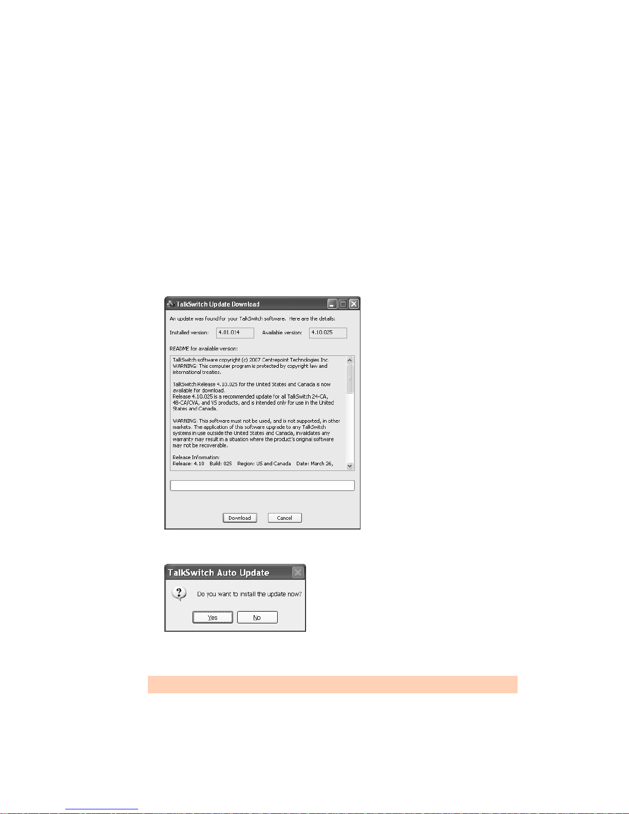
If you prefer to use Windows Explorer or if the install process does not launch automatically:
1. Double-click the My Computer icon.
2. Double-click the CD-ROM/DVD drive.
3. Double-click the Startscreen.exe icon and follow the instructions. After you click the
Finish button, you will see the TalkSwitch icon on your desktop. This means you have
successfully installed the TalkSwitch management software.
Upgrading the TalkSwitch software and firmware
We are continually looking for ways to enhance your communications capabilities. When new
features are added, we provide our users with immediate access to an update directly from
Windows Start menu.
1. Click Start > Programs > TalkSwitch 6.11 > TalkSwitch Auto Update.
If your TalkSwitch management software is due for an update, a window informs you of the
status of your software version. If you need an update, you have the option to download
the update.
2. Click the Download button to download the update. After the file is downloaded, the Auto
Update program prompts you to install the update.
3. Click Yes to install the update. You can also install the update later from C:\Program
Files\TalkSwitch\TalkSwitch Configuration 6.11.
The TalkSwitch management software must be closed in order to install the update.
TALKSWITCH INSTALLATION 6
Page 26
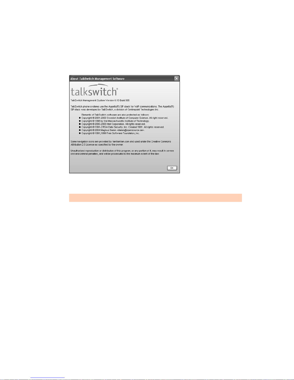
Alternatively, you can check the versions you are running once the system is connected by
following the three steps below.
Step 1 — Check current version
To identify the appropriate update file, you must determine your TalkSwitch software and
firmware versions. To find your TalkSwitch software version number, choose Help > About
TalkSwitch Management Software.
Write down the software number. Go to the support section of the TalkSwitch website at http://
global.talkswitch.com. The instructions help you select and download the appropriate upgrade.
The instructions on our website take precedence over any instructions in this user guide.
Step 2 — Download new software and firmware
When you double-click on the appropriate version for downloading, a window displays, asks you
to enter a filename and select a folder for the download. We suggest leaving the filename as it is
and saving it to your PC in C:\Program Files\TalkSwitch\TalkSwitch Configuration 6.11.
Once the download is complete, begin your upgrade by double-clicking on the install file or
using the Run command on the Windows Start menu. A series of windows will guide you
through the installation process.
This process updates your TalkSwitch management software to a newer version. You still need to
update the firmware to take advantage of new features. The new firmware file is placed in the
TalkSwitch directory after running the install program.
Step 3 — Updating the firmware
The last step is to update the firmware. Make sure your TalkSwitch is connected to your PC.
1. Open the TalkSwitch management software.
2. Choose Tools > Update Firmware.
TALKSWITCH INSTALLATION 7
Page 27

The update time varies depending on the connection type, how many files are needed and how
many units are updated. On average the process takes between 1 and 5 minutes. The LED lights
on the TalkSwitch front panel show diagnostic indicators for the update. See What the flashing
lights mean on page 2. When the update is completed, you are prompted to reboot TalkSwitch.
In the window, click the Proceed button.
Should the firmware update fail, please repeat the update process above. If the problem persists,
contact your reseller or TalkSwitch.
Most firmware updates do not alter your system configuration. In certain circumstances, during
a major system update, the configuration file may get reset to default values.
When you configure a unit for the first time and every time you modify the configuration, we
recommend you save your configuration file to your PC and preferably to removable media (3.5"
Floppy, CD-ROM disc or Flash stick) as a back-up. This avoids having to reconfigure the entire
system in case of a hardware failure.
If you have to replace your computer, please download the latest install file from our website
and follow steps 2 and 3 above. Run the install program. In case of a major system update,
copy the back-up of your configuration file to
C:\Program Files\TalkSwitch\TalkSwitch Configuration 6.11.
INITIAL CONFIGURATION
Once your software is installed and your TalkSwitch is connected directly to a PC or via a switch/
hub to the LAN, you can customize the TalkSwitch system with the TalkSwitch
management software.
If you connect TalkSwitch to your telephone lines, it will do the following:
• An incoming call on any line will ring all local extensions.
• A receptionist can manually transfer calls to local extensions or voicemail.
• Every local extension will have a voice mailbox.
Recommendation: To minimize the disruption time of your telephone lines during the
system setup, we recommend you configure the unit before you connect all the local
extensions and telephone lines to the TalkSwitch unit.
TALKSWITCH INSTALLATION 8
Page 28

SELECT LOCATION FOR INSTALLATION
Select a suitable location for installation of TalkSwitch.
TalkSwitch can be installed on a desktop or mounted on a wall. It can be installed in a office or
communications or utility room.
Choose a location that meets the following requirements:
• Ambient temperature between 0–35°C.
• Away from heat sources and direct sun light.
• Avoid rooms with excessive humidity or dust.
• Within 1.5m of a power socket.
• Close to telephone company demarcation point for telephone lines, or sockets, and any inbuilding telephone wiring connection point.
• Away from any electronic devices that emit radio signals.
• Away from hazardous or explosive materials.
When installing multiple TalkSwitch units, do not stack units on top of each other.
If TalkSwitch has been exposed to low temperatures prior to installation, wait until the system
has reached room temperature before connecting the power cord to avoid damage due
to condensation.
Caution: Use only the power adapter and power cord supplied with your TalkSwitch. Check
the supply voltage matches the rating on the power adapter label. If your supply voltage does
not match the power adapter rating, please consult your reseller. For safe operation, the
TalkSwitch power adapter must be connected to a power supply socket with a third pin
(ground/earth).
Caution: Surge protection devices are recommended to protect TalkSwitch in areas subject to
lightning or power surges. Please consult your reseller for recommended surge
protection devices.
Wiring
Make the most of your phone system with optimal home/office wiring. If you need help wiring
your house or small office and are not sure where all the jacks are or what colors of wires to use,
refer to Appendix H: Home/Office Wiring Guide on page 268.
Figure 6: An example of residential wiring
TALKSWITCH INSTALLATION 9
Page 29
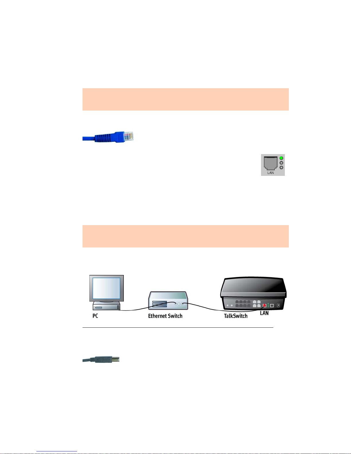
CONNECT TALKSWITCH TO A NETWORK OR A PC
Connect the AC adapter provided with TalkSwitch from an electrical outlet to the TalkSwitch
unit. Never use a power adapter other than the one that came in the TalkSwitch package.
To configure the TalkSwitch unit, connect the unit via ethernet, USB or Internet to the PC with
the TalkSwitch management software installed.
The computer connection is only needed to change the configuration settings. It can remain
disconnected at other times. If you encounter difficulties opening the TalkSwitch
management software, check that all your wires and plugs are securely connected.
Ethernet connection
An Ethernet cable is supplied with specific unit models. This
connection requires a LAN and a PC on the same switch. Any PC on
the LAN can configure the unit.
The top LED on the back panel beside the LAN port indicates a connection has
been established with a switch or hub.
A PC can connect directly to the TalkSwitch LAN port using a ‘cross-over’ cable
equipped with RJ-45 connectors.
You can use a PC that has a wireless connection to the LAN. If the router has uPNP enabled, the
TalkSwitch management software can auto-discover and connect to the TalkSwitch unit. If the
router does not have uPNP enabled, the TalkSwitch management software cannot auto-discover
the TalkSwitch unit. However the software can connect to the TalkSwitch unit if you specify its
IP address after starting the software.
Sharing computer data and TalkSwitch voice data, on the same hub can cause voice
degradation during high traffic periods. For best results, place TalkSwitch units on a switch, or
on their own hub.
1. Connect your PC to the hub or switch using an Ethernet cable.
2. Connect the TalkSwitch unit to your hub or switch using the supplied Ethernet cable.
Figure 7: Ethernet connection
USB connection
A USB cable is supplied with specific models. The PC and TalkSwitch unit
must be in close proximity.
1. Connect the cable to a USB port on your PC and to the USB port on the back of TalkSwitch.
TALKSWITCH INSTALLATION 10
Page 30

Internet connection
An Ethernet cable is supplied with specific unit models.
The top LED on the back panel beside the LAN port indicates a connection has been established
with a switch or hub.
1. Connect the TalkSwitch unit to your hub or switch using the supplied Ethernet cable.
2. To support remote management over IP, map the TCP/IP 9393 port from your firewall to
TalkSwitch. Please refer to the manual for your router/firewall to activate port forwarding.
CONNECTING TELEPHONE LINES
Advisory: In order to minimize disruption to your business, you may want to configure
TalkSwitch before connecting it to your telephone lines and local extensions.
The TalkSwitch unit will perform call handling, and will route all incoming calls to the
extensions. Call handling includes call forwarding, transferring, voicemail, etc. Telephone lines
are not directly connected to any of the local extensions. The TalkSwitch configuration
determines how calls are routed to local extensions.
1. Connect the TalkSwitch unit to the telephone company’s line sockets using the 2-wire
single-line telephone cables provided, beginning with L1. Take note of which telephone line
is connected to each line port. This information will be used in the configuration section.
If you have two telephone lines out of one phone jack, you will require a dual-to-twosingle-line adapter or replace the two-line cord with two single-line cords.
Caution: The TalkSwitch line jacks are sensitive to high-voltage spikes from lightning. If you
live in an area where electrical storms occur regularly, we recommend you protect TalkSwitch
by plugging the telephone cords coming from the TalkSwitch line jacks to a surge protection
device connected to the telephone lines.
CONNECTING LOCAL EXTENSIONS
A local extension is an analog extension, IP extension or external IP extension. An analog
extension is a device (standard phone, cordless phone, fax machine or modem) connected to
extension jack E1–E8. An IP extension is an IP phone connected via LAN. An external IP
extension is an IP phone connected via the Internet, and requires the TalkSwitch unit to have
VoIP capability.
Connect a single-line device to an extension jack the same way you would plug it into a
standard telephone wall jack.
Connect a standard phone that does not require external power to extension jack E4 to ensure
communications during a power failure. In the event of a power failure or loss of power to
TalkSwitch, the phone on extension jack E4 is able to receive and make calls on line L1.
Connecting a single-line analog phone
This is the basic, simple set-up. All functionality including transferring calls, forwarding calls
and voicemail, is handled by the unit. Even the most basic of phones, once connected, will
inherit these functions.
TALKSWITCH INSTALLATION 11
Page 31

Each phone is connected to an extension jack. Calls on extension 111 ring the phone connected
to jack E1. Calls on extension 112 ring the phone connected to jack E2 and so on.
Figure 8: Single-line phones
Connecting a two-line analog phone
You can plug a two-line phone into two extension jacks of the TalkSwitch unit. You can then
configure each telephone line to ring a specific extension. For example, line 1 can ring
extension 111, which will show Line 1 as active. Line 2 can ring extension 112, which will show
Line 2 as active and so on.
Figure 9 shows extensions 111 and 112 connected to a two-line phone that uses separate jacks
for each line.
Figure 9: Two-line phone
If your two-line phone does not have separate jacks, you can use a splitter to join the two lines
as shown in Figure 10.
Figure 10: Two-line phone on splitter
TALKSWITCH INSTALLATION 12
Page 32

A four-line phone can use two splitters to join the four lines as shown in Figure 11.
Figure 11: Four-line phone on two splitters
Connecting an IP phone
Plug the IP phone into your switch/hub and configure it as described in Adding IP phoneS on
page 82. If you are using an unsupported IP phone, refer to its user guide for
configuration instructions.
Connecting a modem
Plug the modem’s telephone cable into a unit extension jack. Your modem is now an extension
that can access all lines and take advantage of call routing features.
A modem connected to a TalkSwitch unit operates at up to 28 kbps.
If you don’t want to change your dial-up settings for the modem, enable Direct Line Access for
the extension associated to the modem. For more information, see Direct line access on page 62.
TALKSWITCH INSTALLATION 13
Page 33

Connecting a fax machine
If you are connecting a fax machine to a TalkSwitch unit, plug it into an extension jack.
TalkSwitch provides you with three options to configure your fax machine. Choose the best
option for your office.
Option 1 — Dedicated fax line
You may already have an incoming dedicated fax line. You can leave this line directly connected
to your fax machine. Connect the remaining telephone lines to your unit. Telephone lines will be
handled by the unit and your fax will work the way it has always worked.
Figure 12: Dedicated fax line
Advantages: It’s easy to set up and you don’t need to change the way your fax handles calls.
Disadvantages: The dedicated fax line cannot be shared with the other phone devices (i.e. you
cannot make an outbound voice call on your fax line). The dedicated fax line costs money, and
may not be used as frequently as it could be.
Option 2 — Distinctive ring
Distinctive ring is a service provided by your phone company. A second phone number is added
to a telephone line. A call to either phone number will ring the same line, but with different
ring patterns. You can use one ring pattern to indicate a fax.
Figure 13: Distinctive ring
Advantages: This option does not require a second physical line for faxes. More telephone lines
can be added as you grow. You can keep the same fax arrangement.
Disadvantages: Your phone company may charge a fee for the distinctive ring. If you choose
this option, you will require the distinctive ring service from your telephone company.
TALKSWITCH INSTALLATION 14
Page 34

Option 3 — Automatic fax detection via the auto attendant
The auto attendant can detect incoming fax calls and route them accordingly. To enable this, an
auto attendant must answer all incoming calls. It will listen for a fax tone (CNG) to determine if
the call is an incoming fax. If so, the call is routed to the fax machine. You must create an auto
attendant to use this method.
Figure 14: Automatic fax detection via auto attendant
Advantages: Calls are automatically handled for you. Distinctive ring service is not required.
Any telephone line can receive a fax or a call, making better use of your resources.
Disadvantages: Some older fax machines do not emit a fax tone (CNG). Therefore, the auto
attendant cannot detect incoming faxes from those devices. If your auto attendant volume is set
too high or if your telephone lines are noisy, the auto attendant may have difficulty detecting
the incoming fax tone and therefore not route the call to the fax machine. You can solve this
problem by adjusting the volume. For more information, see Telephone Lines > Audio on
page 184.
CONNECTING TO THE PA (PUBLIC ADDRESS) JACK
The PA jack can be connected to a PA system for overhead paging, screening voicemail and
playing music on hold. The PA jack requires a 1/8" (3.5 mm) mono phono connector. If your
system has multiple TalkSwitch units, use a splitter to connect each TalkSwitch unit to the
PA system.
SETTING UP MUSIC ON HOLD
Callers tend to react more positively to waits or transfers if they hear music. You can also play an
advertisement or provide information about your company.
External audio source
The MUSIC jack is designed to support an external audio source like a CD player, tape player or
PC media player.
Advantages: The length of the recording is not limited by the amount of memory in the
TalkSwitch units. All of the TalkSwitch memory is available for voicemail and auto attendants.
Different TalkSwitch units can have different music on hold.
Disadvantages: Extra dedicated equipment must be connected and running constantly. A
separate sound source is required for each unit.
TALKSWITCH INSTALLATION 15
Page 35

1. Connect the audio source via its headphone output to the MUSIC jack. Use a cable with a
1/8" (3.5 mm) mono phono connector.
2. If your system has multiple TalkSwitch units, either use a different audio source for each
unit, or use a splitter to connect the one audio source to each unit.
Internal audio file
You can load an audio .wav file into the TalkSwitch unit. If you have more than one unit
connected by LAN, the .wav file is automatically copied to each unit.
Advantages: No additional equipment is required. All units use the same file, which provides
seamless music for calls transferred across the system.
Disadvantage: The length of the recording is limited by the amount of memory in the
TalkSwitch units. Less time is available for voicemail and auto attendants.
The recording time for internal music on hold, voicemail, and the auto attendants is shared on
the TalkSwitch unit. You can expand the built-in memory using memory cards.
NETWORKING TALKSWITCH UNITS ON A LAN
Up to four units can be networked together over a LAN to increase the number of telephone
lines and extensions in your phone system.
Connecting TalkSwitch units to a LAN
You can plug your unit(s) into your existing LAN or operate it on its own LAN with an Ethernet
switch. Ensure the firmware on all units is updated before adding them to the LAN.
Check the support section at http://global.talkswitch.com for the latest updates.
TalkSwitch unit enclosures are not designed for stacking. We recommend wall-mounting units
to maximize airflow and keep the units from overheating.
Ethernet switch
An Ethernet switch provides direct communication between units, thus keeping the voice-overLAN data isolated from other data on the network.
1. Connect up to four units to an Ethernet switch.
2. Connect a computer to the Ethernet switch.
3. Power up and configure the units.
4. After configuring the units, connect the IP extensions to the Ethernet switch.
TALKSWITCH INSTALLATION 16
Page 36

It is important that you place the IP extensions on the same subnet as TalkSwitch. For example,
if your TalkSwitch unit has the IP address 192.168.1.200, your IP extensions should use IP
addresses in the range 192.168.1.xxx that do not conflict with other IP addresses.
MUSIC PA
MUSIC PA
E5 E6 E7 E8
E1 E2 E3 E4
E5 E6 E7 E8
E1 E2 E3 E4
L4L3
PF
L1
L2 USB POWER
L4L3
PF
L1
L2 USB POWER
E5 E6 E7 E8
MUSIC PA
LAN
LAN
Reset
1Internet 234
E1 E2 E3 E4
POWER
L4L3
PF
L1
L2 USB POWER
LAN
Figure 15: Three units connected via an Ethernet switch
Power up all the TalkSwitch units
Connect the provided AC adapters to each unit and plug the adapters into available power
outlets. Turn the units on by pressing the Power button on the front of each unit. The lights on
the front panels of the units will flash. This means they are powered up and connected to the
LAN, but their ID numbers are not set.
Setting or changing the unit ID
Units are shipped from the manufacturer with unit ID 1. If two or more units are placed on the
same LAN with the same unit ID number, it causes a conflict. The four line lights on the front
panel of each unit will start flashing. You have to assign a different unit ID to each unit.
1. Connect an analog phone to one of the extension jacks on the unit.
2. Press # to enter command mode.
3. Dial the system password + #.
4. Now, you have the following options:
Keys Result
00 + # Responds with the unit ID number of that particular unit.
01 + # Sets the unit ID to 1.
02 + # Sets the unit ID to 2.
03 + # Sets the unit ID to 3.
04 + # Sets the unit ID to 4.
The system indicates the update was successful and the front panel lights stop flashing after a
few seconds. When the front panel Data light is on solid, the units are ready for network use.
How unit IDs affect system extension numbers
After successfully changing each unit ID to a unique number, it can be identified by the
network. More importantly, each local extension, remote extension, and voice mailbox has a
unique number. Note that dialing 101–108 will ring local extensions 111–118.
TALKSWITCH INSTALLATION 17
Page 37

Unit ID 1 Unit ID 2 Unit ID 3 Unit ID 4
Local extensions
(analog/IP)
Local extensions (IP only) 151–158 161–168 171–178 181–188
Remote extensions 210–219 220–229 230–239 240–249
Local mailboxes 111–118
Remote mailboxes 210–219 220–229 230–239 240–249
General mailboxes 410–419 420–429 430–439 440–449
111–118 121–128 131–138 141–148
151–158
121–128
161–168
131–138
171–178
141–148
181–188
Keep track of the lines and extensions
To keep track of the extensions and telephone lines connected to each unit, label each unit with
its unit ID. It simplifies matters when you need to add or remove extensions and lines.
Optimizing the system for networked use
TalkSwitch units have been designed to operate optimally when in a networked state. Below are
a few items that have been designed for better network use.
Configuration settings
All units are cloned with identical settings. If a unit has disappeared off the network (adapter
unplugged, LAN disconnected, LAN failure, etc.), the system can still handle the calls since it
retains the configuration settings of the missing unit. If an extension or a voice mailbox cannot
be reached, the caller hears a system prompt: “The extension you are trying to reach is currently
unavailable, please try again later.”
Outgoing line hunt groups
When two or more units are on a LAN, the system tries placing calls out on the same unit the
call originates from. This avoids using a line across the LAN on another unit, which helps to
minimize the LAN traffic and optimizes the opportunity for all inbound calls to connect across
the LAN if required.
Auto attendants
There are a total of nine auto attendants that are shared by all units on the LAN. When an auto
attendant is recorded on any unit, it is automatically copied to all other units on the LAN. This
design minimizes LAN traffic and provides functionality back-up in case a unit or units have
disappeared off the network (adapter unplugged, LAN disconnected, LAN failure, etc.). In this
event, all units can still answer inbound calls with the same auto attendant messages.
Voicemail
All local extension and remote extension voicemail data is stored on the unit the extension is
connected to. For example, all greetings, dial-by-name directory names and voicemail messages
for extensions 121–128, 161–168, 220–229 and mailboxes 420–429 are stored on unit 2. If a
unit is completely filled with voicemail messages, the system will not accept any more messages
for its extensions. However the other units will accept messages for their extensions. If you need
more memory, TalkSwitch memory cards can be purchased from your reseller. To view the
memory usage of each TalkSwitch unit and each mailbox, choose Tools > Memory Usage or
choose Tools > Voicemail Manager > Mailbox Status.
TALKSWITCH INSTALLATION 18
Page 38

Special considerations when connecting multiple units to a LAN
Multiple TalkSwitch units on a LAN will function as a single phone system. Some features are
expanded as you add units, and other features are not.
As you add more units, the number of telephone lines, local extensions, VoIP lines, remote
extensions and voice mailboxes will increase.
For example, if you have a 480vs and a 244vs connected on the same LAN, the system can
support 6 telephone lines, 32 local extensions, 4 VoIP lines, 20 remote extensions, 32 local voice
mailboxes, 20 remote voice mailboxes, and 20 general voice mailboxes.
The features listed below are not affected by the number of units on the LAN, so capacity will
not increase as you add units.
Feature Description
Auto Attendant There are nine auto attendants.
Ring Groups There are ten ring groups (300–309).
Park Orbits There are ten park orbits (500–509).
Music on Hold You can add music on hold to your system by loading an internal music file.
The music file is copied to each TalkSwitch unit, so the music on hold will be
the same for each line of each unit.
Public Address
(PA)
Each unit has a PA output for connection to a public address system. The PA
output for a TalkSwitch unit is only accessible from extensions connected to
that unit. To connect all outputs to a single amplifier, you will require
an adapter.
INCREASING MEMORY CAPACITY
The recording time for internal music on hold, voicemail, and the auto attendants is shared on
the TalkSwitch unit. You can expand the built-in memory using memory cards. Contact your
reseller to purchase memory upgrades.
TalkSwitch memory cards
TalkSwitch memory cards are specifically formatted for use with TalkSwitch units. They allow
you to add additional voicemail message capacity to your unit. Voicemail memory is used to
store greetings and messages left in voice mailboxes. It is also used to store music on hold, auto
attendant greetings and announcements.
Figure 16: Memory card
Installing a memory card
1. Insert the memory card into the memory slot with the gold contact face down and the “This
side up” label showing. You don’t have to turn the unit off or disconnect any of
the telephones.
TALKSWITCH INSTALLATION 19
Page 39

2. Ensure the Total Unit Time has increased in the Mailbox Data window. See Memory Usage on
page 169.
Figure 17: Memory card slot
UPGRADING TALKSWITCH UNITS
As your business grows, your TalkSwitch unit(s) may need upgrading. You have the option of
upgrading your units to VoIP, as well as adding telephone lines and extension jacks. The upgrade
kit consists of a top board you add to your existing TalkSwitch unit, as well as a guide
containing detailed, step-by-step instructions for the upgrade procedure.
Purchase VoIP modules and upgrade boards at your reseller or visit the TalkSwitch website for
more details.
Note that in some cases it may be easier and more cost effective to buy another TalkSwitch unit
than to upgrade an existing unit.
Upgrade TalkSwitch unit Board TalkSwitch
equivalent
Add four VoIP lines 240vs
280vs
480vs
840vs
48-CA
Add eight VoIP lines 240vs
280vs
480vs
840vs
48-CA
Add six telephone lines 240vs
244vs
248vs
Add four extension jacks 240vs
244vs
284vs
Add two telephone lines
and four extension jacks
240vs
244vs
248vs
24-CA
4plus 244vs
284vs
484vs
844vs
48-CVA
8plus 248vs
288vs
488vs
848vs
48-CVAv2
600plus 840vs
844vs
848vs
40plus 280vs
284vs
288vs
240plus
480vs
484vs
488vs
24-CA to 48-CA top
48-CA
board
TALKSWITCH INSTALLATION 20
Page 40

ENABLING LICENSED ADD-ONS
It is possible to enable the following features on your TalkSwitch:
• Attendant Console software
• Call Reporting software
• Extended Warranties
For instructions on enabling TalkSwitch licensed add-ons, see Licensed Add-Ons on page 57.
VERIFYING THE CONNECTIONS
If you are having problems, they could be due to loose cables. Check the following:
1. Are your telephone cables connected to a wall jack at one end and the unit at the other?
Ensure the devices you are using as extensions (telephones, faxes, etc.) are plugged into the
extension jacks located on the back panel of the unit. Do not plug your extensions directly
into a wall jack unless that jack is wired to a unit extension jack.
2. Check the USB or LAN connection between TalkSwitch and your PC.
3. Ensure the unit AC adapter is plugged into a working power outlet and the unit is turned on.
Make sure you are using the AC adapter supplied with your unit. This adapter cannot be
substituted with any other adapter. If your adapter appears to be defective, please contact
your TalkSwitch dealer to order the proper replacement.
If networked, ensure you have the latest firmware loaded on all units.
CONNECTING A TALKSWITCH UNIT TO A PBX
Connecting a TalkSwitch unit to a PBX allows the TalkSwitch unit to answer calls with an auto
attendant. The caller can dial 7 followed by an extension number to reach an extension on
the PBX.
1. Connect one or more PBX extensions to the TalkSwitch telephone line jacks (one PBX
extension per line).
2. Configure the PBX to route incoming calls to the PBX extensions that are connected to the
telephone line jacks of the TalkSwitch unit.
3. Configure the auto attendant to answer after a specified number of rings.
4. Record the auto attendant messages. They should list the extensions with the digit 7 in
front of them.
5. Set the PBX extension length. See From auto attendant tab on page 177.
For example, if you have chosen the PBX extension length to be 3 digits and John Smith’s
extension is 111 on the PBX, the auto attendant should say: “To speak with John Smith, dial
7111.” When the caller dials 7111, the TalkSwitch unit puts the caller on hold and transfers
them to extension 111 on the PBX.
This feature only works with PBXs that use hook flash as a transfer method. Please contact
your PBX manufacturer for transfer details.
TALKSWITCH INSTALLATION 21
Page 41

CHAPTER 2
Chapter 2: TalkSwitch Config uration
TALKSWITCH CONFIGURATION
INTRODUCTION
This chapter contains detailed information about all the features in the TalkSwitch management
software, with step-by-step instructions on how to customize these features to best suit
your needs.
STARTING THE TALKSWITCH MANAGEMENT SOFTWARE
When a unit is being configured, it is locked to prevent other computers or persons using a
phone from configuring changes at the same time. If you leave the software open for longer
than one hour, the unit unlocks itself to allow configuration changes.
1. Press the Power button to turn on your TalkSwitch unit.
2. Turn on your computer.
TALKSWITCH CONFIGURATION 22
Page 42

3. Double-click the TalkSwitch icon on your desktop to open the TalkSwitch management
software. You can also click Start > Programs > TalkSwitch 6.11 > TalkSwitch
Configuration 6.11. The Configuration Selection page appears, and the software attempts
to detect your TalkSwitch unit.
4. Select your language. You can select English, Français or Español.
5. Once the software detects your TalkSwitch unit, click Configure Auto-Detected TalkSwitch
System. The software loads the configuration from the TalkSwitch unit, and the About
page appears.
6. If the software was unable to detect your TalkSwitch unit, check that all your wires and
plugs are securely connected, and then click Retry Auto-Discovery. The software loads the
configuration from the TalkSwitch unit, and the About page appears.
7. If auto-detection does not work:
a) Click Connect to Different System. The Connect Via IP window appears.
b) Enter the URL / IP address and Port of the TalkSwitch unit, and then click OK. This is the
public IP address or FQDN of the TalkSwitch system. The software loads the configuration
from the TalkSwitch unit, and the About page appears.
TALKSWITCH CONFIGURATION 23
Page 43

8. To open a configuration file:
a) Click Open a Configuration File or Template. The Open File or Template
window appears.
b) Click Open a File. The Configuration File window appears.
c) Browse to the .tsd file, and then click Open. The software opens the configuration file.
TALKSWITCH CONFIGURATION 24
Page 44

ABOUT
The About page displays and allows you to change system information.
1. Select the About page.
The System Information area shows:
• The current time and date programmed into the TalkSwitch system. Clicking the System
time link displays the TalkSwitch Date and Time Properties window. It allows you to
change the date, time, time zone, and NTP server programmed into the TalkSwitch system.
See System time on page 31.
• The current mode. A mode is a period of time when the TalkSwitch system uses a particular
call handling setup for incoming calls. Mode 1 is typically office hours, and Mode 2 is
typically evening and weekend hours. Holiday Mode is when your office is closed for a
statutory holiday or shutdown. Clicking the Current mode link displays the Change Mode
window. It allows you to change the mode of the TalkSwitch system. See Change mode on
page 30.
TALKSWITCH CONFIGURATION 25
Page 45

• The model numbers of the TalkSwitch units in the TalkSwitch system. Clicking the My
TalkSwitch system link displays the Talksw itch Network window. It shows the MAC
address, IP address, model number, firmware version, and length of operation for each
TalkSwitch unit.
To identify a TalkSwitch unit, click the Identify button. The Identify button will change to
a Stop button. All the lights on the front panel will start flashing. Click the Stop button to
end the flashing.
• The number of new voicemail messages in the TalkSwitch system, and the total number of
voicemail messages. Clicking the Voicemail messages link displays the Voicemail Memory
Usage window. It shows message statistics for each voice mailbox. See View mailbox data on
page 120.
• The version number of the TalkSwitch management software.
• When the configuration was last saved to the TalkSwitch system.
• The type of connection to the TalkSwitch system.
• The region of the TalkSwitch system.
TALKSWITCH CONFIGURATION 26
Page 46

ADMINISTRATION
The Administration page allows you to set up the system name, system password, language,
and how to route the call if a user dials 0.
1. Select the Administration page.
Administration
The Administration area allows you to set up the system name and system password.
CAUTION: Use a system password, otherwise the system will be vulnerable to configuration
changes, misuse and/or lock-out by callers or users. If the router has port 9393 mapped to the
TalkSwitch unit for remote configuration, the system will also be vulnerable to anyone on
the Internet.
Change the system password frequently to prevent unauthorized users from making calls or
changing the configuration.
1. Optionally enter the System name. This should be the company name, or a shortened form
suitable for use as caller ID during VoIP calls. If you enter a system name, you will require it
when logging in through a browser for status or call detail record (CDR) information. If you
omit the system name, you can enter talkswitch when logging in through a browser.
2. Enter the System password. It has to be a 4- to 8-digit numeric password, so you can also
enter it on a touchtone phone.
The system password allows access to the configuration. It is entered when you start the
TalkSwitch management software, and when you access the configuration through a local
extension or outside phone.
TALKSWITCH CONFIGURATION 27
Page 47

Language
The Language area displays the language loaded into the TalkSwitch system, and allows you to
load and remove language files.
1. To change the language files loaded into the TalkSwitch system, click Edit. The Language
File Management window appears, listing loaded language files.
a) To load a language file, click Add, and then select the language file.
b) To remove a language file, select the language, and then click Remove.
2. Select the default language for prompts heard by callers and users in the Default language
for system prompts to callers list.
Dial 0 routing
The Dial 0 routing area allows you to select how the system will route the call if a user dials 0.
For example, you can configure the system to connect the user to the receptionist at
extension 114.
1. Select the action in the Connect to list. Choices are:
• perform no action — Does not connect to a resource.
• go to voicemail — Connects to the selected voicemail.
• go to local extension — Connects to the selected local extension.
• go to remote extension — Connects to the selected remote extension.
• go to ring group — Connects to the selected ring group.
• play announcement — Plays the selected announcement.
• go to auto attendant — Connects to the selected auto attendant.
• queue at ring group — Connects to the call queue of the selected ring group.
• lookup name directory — Accesses the dial-by-name directory.
• go to VoIP location — Connects to the selected VoIP number within the TalkSwitch
VoIP network.
2. Select the resource. Depending on the action, resources are voice mailboxes, extensions,
announcements, auto attendants, or VoIP numbers within the TalkSwitch VoIP network.
TALKSWITCH CONFIGURATION 28
Page 48

SCHEDULING
A mode is a period of time when the TalkSwitch system uses a particular call handling setup for
incoming calls. Mode 1 is typically office hours, and Mode 2 is typically evening and weekend
hours. Holiday Mode is when your office is closed for a statutory holiday or shutdown.
The TalkSwitch system can use a different call handling setup for each mode, and can
automatically change mode with the time of day, day of week and on holidays. This way it can
handle calls in different ways according to a schedule.
The Scheduling page allows you to set up Mode 1, Mode 2 and Holiday Mode. You can also adjust
the time and date, and can switch modes manually.
Ensure the TalkSwitch management software is closed during automatic mode switching, or if
an administrator is manually switching modes using a phone. In these cases the mode cannot
switch while the TalkSwitch management software is open.
Note that the mode can switch while the TalkSwitch management software is open, if the user
is manually switching modes using the software, as described later.
1. Select the Scheduling page.
Modes
The Modes area allows you to enable, name and switch modes, and displays the current mode.
1. Enter the Mode 1 label and the Mode 2 label. Note that Mode 1 and Mode 2 are always
available, so you cannot disable the Enable Mode 1 and Enable Mode 2 check boxes.
2. Set up Holiday Mode to handle incoming calls differently during a holiday:
a) Select the Enable holiday mode check box to enable Holiday Mode. The window enables
the Settings button.
TALKSWITCH CONFIGURATION 29
Page 49

b) Enter the Holiday Mode label.
c) Click Settings. The Holiday Settings window appears. The calendar shows the current
date in green.
d) Select your country in the Populate calendar with holidays observed in list, and then
click Populate. The calendar will show your country’s statutory holidays in grey.
e) Using the calendar, select the month and then click the date of the holiday. The date is
added to the Selected Dates area, and the calendar will show the date in blue. Click the
date again to remove it.
f) Repeat Step e until all required holidays have been added.
g) Select the mode in the Use the following call cascade settings for Holiday Mode. Choices
are Mode 1 and Mode 2. This setting determines whether extensions will use their Mode 1
or Mode 2 call cascades during Holiday Mode.
Change mode
The Modes area displays the current mode.
1. To change mode, click Change Mode. The Change Mode window appears.
TALKSWITCH CONFIGURATION 30
Page 50

2. Select the mode. The new mode immediately takes effect. You do not have to save
the configuration.
You can also change the mode by phone.
1. Ensure the TalkSwitch management software is closed.
2. Pick up a local extension, or remotely call the TalkSwitch system.
3. Enter command mode by either pressing # on an analog extension phone, or *55# on an IP
phone.
4. Enter the system password, followed by #.
5. Enter one of the following commands:
• 30 + # to hear the current mode.
• 31 + # to enable Mode 1.
• 32 + # to enable Mode 2.
• 33 + # to enable Holiday Mode.
6. Press * to exit command mode.
Scheduling
The Scheduling area allows you to specify when the TalkSwitch system will change modes.
1. Select the Use automatic mode switching check box to enable the modes. The window enables
the Scheduling area.
2. Select the day.
3. Select whether to use one mode or multiple modes during that day:
•Select Continuously run to use the selected mode the whole day.
•Select Switch modes depending on time to switch between Mode 1, Mode 2 and Holiday
Mode during the day. The window enables the schedule controls.
4. If you selected Continuously run, select Mode 1, Mode 2 or Holiday Mode.
5. If you selected Switch modes depending on time, set when the mode should change. The
default settings are:
• Mode 1 at 9:00 AM on Monday to Friday.
• Mode 2 at 5:00 PM on Monday to Friday.
• Mode 2 continuously on Saturday and Sunday.
System time
The Scheduling area shows the date and time programmed into the TalkSwitch system. Clicking
the Adjust button displays the TalkSwitch Date and Time Properties window. It allows you to
change the date, time, time zone, and NTP server programmed into the TalkSwitch system.
NOTE: You can configure the TalkSwitch system to get the time and date (but not the year or
time zone) from caller ID. See Clock Preferences on page 180.
TALKSWITCH CONFIGURATION 31
Page 51

1. Click Adjust. You can also choose Options > Set Date & Time. The TalkSwitch Date and
Time Properties window appears.
Date & time
The Date & Time area allows you to set the date and time programmed into the
TalkSwitch system.
1. Select the month and date for the TalkSwitch system.
2. Set the time for the TalkSwitch system.
Time zone
The Time Zone area allows you to set the time zone for the TalkSwitch system, and whether
daylight savings time is used in your region.
1. Select the time zone for the TalkSwitch system.
2. If your region uses daylight savings time, select the Automatically adjust clock for daylight
saving changes check box.
TALKSWITCH CONFIGURATION 32
Page 52

NTP server
The NTP Server area allows you to set the NTP (Network Time Protocol) server for the TalkSwitch
system. It provides the same time to the TalkSwitch units and to the external IP extensions.
1. Select the NTP Server tab.
2. Enter the NTP server.
TALKSWITCH CONFIGURATION 33
Page 53

IP CONFIGURATION
The IP Configuration page allows you to set up the TalkSwitch system for Internet
communications. The Internet can be used for external IP extensions, a TalkSwitch VoIP
network, a subscription to a VoIP service, and remote configuration.
1. Select the IP Configuration page.
System IP settings
The System IP Settings area shows IP addresses. By default, Obtain IP and DNS information
automatically is selected and the area shows IP addresses from the router.
1. Change Obtain IP and DNS information automatically to Use configured IP and DNS
information in order to lock in the IP addresses.
2. In some cases, the System IP Settings area may be blank because your router has not
delivered the IP addresses. If so, enter the following IP addresses from your
LAN administrator:
a) Enter a static IP address for each TalkSwitch unit in the Unit IP address boxes.
b) Enter the Subnet mask for the LAN. This address determines the subnet the unit IP
addresses belong to.
c) Enter the IP address of the Default gateway on your network. A gateway is a hardware
device that connects the office network to the Internet. The router may act as
default gateway.
d) Enter the IP address of the Preferred DNS server. DNS is a service used to resolve a domain
name to an IP address. The router may act as DNS server.
e) If applicable, enter the IP address of the Alternate DNS server.
TALKSWITCH CONFIGURATION 34
Page 54

TalkSwitch proxy
If your TalkSwitch system has multiple TalkSwitch units, the TalkSwitch Proxy area displays and
allows you to change the unit acting as local proxy. The local proxy handles Internet
communications for the TalkSwitch system. It establishes connections across the Internet, and
then routes Internet data to and from each TalkSwitch unit. The lowest numbered TalkSwitch
unit acts as local proxy by default.
The router must map the SIP, TFTP and HTTP ports to the local proxy. See Router port forwarding
on page 36.
1. If necessary, click the Change Proxy button. The Change Proxy window appears.
2. Select the TalkSwitch unit.
Public IP address
The Public IP address section allows you to set up Internet parameters so the TalkSwitch system
can communicate with other locations over the Internet.
1. Set the Type of public address. Choices are:
• Dynamic public IP address — This is the default setting. Your ISP (Internet Service
Provider) will assign different public IP addresses to your location. The TalkSwitch
system will check its public IP address every five minutes. When the public IP address
changes, the TalkSwitch system will automatically use the new one. This allows it to
manage VoIP calls properly.
If Dynamic public IP address is selected, the window completes the Current public IP
address, and sets Public IP address-checker server name to checkip.talkswitch.com. This
server runs an IP checker application that provides public IP addresses to TalkSwitch
systems. You cannot change these items.
• Static public IP address — A static IP address is fixed. Your ISP assigns the static IP
address. If this location will have the SIP server for a TalkSwitch VoIP network, we
recommend using a static IP address.
If Static public IP address is selected, the window allows you to enter the Current public
IP address, and disables the Public IP address-checker server name box.
2. If you selected Dynamic public IP address, enter the Fully qualified domain name (FQDN). Get
the FQDN from your ISP. The FQDN is only required if this location is the SIP server for a
TalkSwitch VoIP network, or has external IP extensions.
A DDNS (Dynamic Domain Name Service) provider such as www.dyndns.com matches your
dynamic IP addresses to your FQDN, so your TalkSwitch VoIP network or external IP phones
will continue to work when the IP address changes.
If you are using DDNS, ensure your router supports your DDNS service, and configure it to
update the DNS servers.
TALKSWITCH CONFIGURATION 35
Page 55

If your router does not support DDNS, download one of the applications specified on
www.dyndns.com. To update the DNS servers, the application needs to run on a PC
connected to the same LAN as the TalkSwitch system.
3. If you selected Static public IP address, enter the Current public IP address from your ISP.
Leave the Fully qualified domain name box blank.
If the TalkSwitch unit is not behind a router, or if a private virtual network is used, the
public IP address should be set to the local IP address of the TalkSwitch unit acting as
local proxy.
Note that it will take up to one minute for the new static public IP address to take effect.
Router port forwarding
The Router Port Forwarding area displays the type of gateway device (i.e. the type of router), the
IP address of the gateway (i.e. router), and whether router configuration is required.
A router is a gateway between the local area network and the Internet. Most routers have a
firewall to block unwanted data from the Internet. For voice data to reach the TalkSwitch system
through the firewall, port forwarding is required. Port forwarding allows the router to map ports
to the IP addresses of the TalkSwitch units. Valid Internet data will use the ports to go through
the firewall to the TalkSwitch units.
If you are setting up external IP extensions, a TalkSwitch VoIP network, or a VoIP service that
doesn’t handle port forwarding, port forwarding is required.
If port forwarding is required, and your router supports uPNP (Universal Plug and Play), ensure
uPNP is enabled. The TalkSwitch system will use uPNP to automatically set up port forwarding,
and the Automatic (uPNP Enabled) link will appear. No router configuration is required.
If port forwarding is required but your router doesn’t support uPNP, or automatic port
forwarding doesn’t work, the Manual Port Mapping Required link will appear. You will need to
configure the router as described below.
1. If required, click the Manual Port Mapping Required link. The Manual Port Mapping
window appears. It lists the packet type, port number, IP address and protocol of each
required port.
TALKSWITCH CONFIGURATION 36
Page 56

2. To access the router configuration:
a) Click the link containing the IP address of the gateway. The default browser starts, and
prompts you for the router’s user name and password.
b) Enter the router’s user name and password. The browser shows a setup screen.
c) Navigate to the screen used to set up port forwarding. See your router documentation.
d) Set up port forwarding using the information from the Manual Port Mapping window.
See your router documentation for instructions on how to map ports. For information on
configuring routers and mapping ports, visit http://www.portforward.com/english/
routers/port_forwarding/routerindex.htm.
3. To check the status of each port through the firewall, click Check Firewall. The Test
Firewall window appears.
4. Select the services you want to check.
5. Click Test Ports. The system will check the ports of the selected services.
Configuring the router manually
If you cannot access the router configuration through the IP Configuration page, configure the
router manually.
1. Open the router configuration and navigate to the screen used to set up port forwarding.
See your router documentation.
2. Map port 5060 (Type: UDP) to the TalkSwitch unit acting as local proxy. Port 5060 is the
default port for forwarding SIP signaling data to the TalkSwitch system.
If required, you can map a different port. In this case, enter the port in the SIP signalling
port box of the VoIP Settings window.
3. Map the following ports (Type: UDP) to the TalkSwitch units. These RTP ports forward voice
traffic to the TalkSwitch system by default.
VoIP Lines/Unit Unit 1 Unit 2 Unit 3 Unit 4
4 6000–6006 6010–6016 6020–6026 6030–6036
8 6100–6114 6200–6214 6300–6314 6400–6414
TALKSWITCH CONFIGURATION 37
Page 57

If required, you can map different ports. In this case enter the first port in the Starting RTP
port box of the VoIP Settings window.
4. If you are setting up external IP extensions, map port 69 (Type: UDP) to the TalkSwitch unit
acting as local proxy. Port 69 allows the TalkSwitch system to configure external
IP extensions.
5. If you are setting up TalkSwitch IP phones as external IP extensions, map port 8484 (Type:
TCP) to the TalkSwitch unit acting as local proxy. Port 8484 allows the TalkSwitch system to
configure TalkSwitch IP phones as external IP extensions.
6. Map port 9393 (Type: TCP) to the TalkSwitch unit acting as local proxy. Port 9393 allows
remote configuration of the TalkSwitch system.
7. If available, enable Quality of Service (QoS) to give voice traffic priority over data.
8. Save the configuration to the router.
ON-HOLD/RINGBACK
Music on hold plays when a caller is on hold, or is being transferred to an extension. The system
plays a double beep tone or ringback tone by default, but you can have it play music or a
recorded message instead.
The TalkSwitch system can play music on hold from an internal .wav file or from an external
audio source. An external audio source is a CD player or MP3 player. It must be connected to the
MUSIC jack on the back of each TalkSwitch unit. See Setting up music on hold on page 15.
The recording time for internal music on hold, voicemail, and the auto attendants is shared on
the TalkSwitch unit. You can expand the built-in memory using memory cards.
The On-Hold/Ringback page allows you to set up music on hold.
1. Select the On-Hold/Ringback page.
TALKSWITCH CONFIGURATION 38
Page 58

On-hold settings
The On-hold Settings area allows you to select the sound to play while the caller is on hold.
1. Select the sound to play while the caller is on hold. Choices are:
• Play “double beep” tones — Plays a “beep beep” sound.
• Play music whose source is connected to the MUSIC jack — Plays music from a CD player
connected to the MUSIC jack. See Setting up music on hold on page 15.
• Play music from file loaded on TalkSwitch — Plays the .wav file loaded into the
TalkSwitch system.
2. If you selected Play music from file loaded on TalkSwitch:
a) Obtain an 8 kHz, 8 bit, Mono, u-Law .wav file that contains the music or recorded
message. You can download free music on hold from the mytalkswitch section of the
TalkSwitch website.
You can also convert .mp3 and other file formats to .wav with a utility like Audio
Converter and Ripper from www.audioi.com.
b) Click Load Wav file. The Select Wav File window appears.
c) Click Browse to select a .wav file, and then click Select Wav File. The system will load
the .wav file into the TalkSwitch unit(s), and will display the file size and date loaded.
3. Adjust the volume of music on hold.
a) Check the volume by placing a test call and going on hold.
b) Change the volume by setting the Playback volume for music file list. Choices are:
•Loudest
• Louder
•Default
•Quieter
•Quietest
c) Choose File > Save.
You must save the configuration for the volume setting to take effect.
d) Repeat Steps a to c.
TALKSWITCH CONFIGURATION 39
Page 59

Transfer settings
The Transfer Settings area allows you to select the sound to play while the caller is being
transferred from an auto attendant or to another extension.
1. Select the sound to play while the caller is being transferred. Choices are:
•Music — Plays music on hold as configured in the On-Hold Settings area.
• Ringback — Plays the ringback tone, which is the normal sound heard when the other
person’s phone is ringing.
Deleting a music on hold file
You can delete a music on hold file. This may be required if you need more space for voicemail
messages. In this case you can use an external audio source for music on hold, or you can
upgrade the memory capacity of the TalkSwitch units. See Increasing memory capacity on
page 19.
1. Click Delete Wav File. The system deletes the .wav file from the TalkSwitch unit(s).
Playing music on hold on the PA system
You can play music on hold through the PA jack.
1. Dial *80 to play or stop playing music on hold through the PA jack.
If music on hold is playing through the PA jack, and a user dials *0 to make an overhead page,
the overhead page will interrupt the music on hold. However, if the PA jack is configured for
voicemail screening, and music on hold is playing, voicemail screening will not interrupt the
music on hold. See PA Output on page 174.
EMAIL SERVICE
The TalkSwitch system can send an e-mail if a voicemail message has been left in a mailbox. The
e-mail includes the caller ID, and can include the voicemail message as an attachment.
The e-mail can optionally include links to delete or save the voicemail message. If you delete the
voicemail message, it will be removed from the TalkSwitch system. If you save the voicemail
message, the system will change its status from “new” to “saved”. A voicemail message that is
saved will no longer activate the new message indicator on the user’s extension.
The system can send notification to up to four e-mail addresses per mailbox. For example, if a
caller leaves a message in the general mailbox for the sales group, the system can send an e-mail
to four members of the sales group.
An e-mail address can be assigned to multiple mailboxes. For example, the system can send emails to a user if callers leave messages in the user’s local extension mailbox, remote extension
mailbox or a general mailbox.
The Email Service page allows you to maintain e-mail addresses, set up the e-mail server
parameters, and test the e-mail server.
TALKSWITCH CONFIGURATION 40
Page 60

1. Select the Email Service page.
Email notification settings
The Email Notification Settings area allows you to add up to 255 e-mail addresses.
1. Select a slot for the e-mail address.
2. Enter the recipient’s Full name.
3. Enter the recipient’s Email address.
4. Select the Notification option. Choices include:
• Include voice message as attachment — Attaches the voicemail message to the e-mail as
a .wav file.
From: TalkSwitch Voicemail
Sent: April 18, 2008 2:53:30 PM
Subject: From: ext 112
Attachments: voice_message_111.wav (68 KB)
_____________________________________
Voice Mailbox 111
New message from ext 112
Received: Friday, April 18 at 2:52pm
Length: 6 seconds
Total un-reviewed messages: 5
Total saved messages: 0
____________________________________
TALKSWITCH CONFIGURATION 41
Page 61

TalkSwitch Voicemail Management
Save message Delete message
____________ ______________
Note: It may take up to 2 minutes for the message to be saved/
deleted from your mailbox.
• Email notification only (full length) — Does not attach the voicemail message to the e-
mail, but includes full details about the contents of the voice mailbox.
From: TalkSwitch Voicemail
Sent: April 18, 2008 2:53:30 PM
Subject: From: ext 112
_____________________________________
Voice Mailbox 111
New message from ext 112
Received: Friday, April 18 at 2:52pm
Length: 6 seconds
Total un-reviewed messages: 5
Total saved messages: 0
____________________________________
• Email notification only (SMS length) — Does not attach the voicemail message to the e-
mail, and sends minimum details about the message. The notification is less than 130
characters, so is short enough to be sent in one e-mail to a cell phone.
From: TSvm
Sent: April 18, 2008 2:53:30 PM
Subject: New msg
Mbox 111
Msg from ext 112
Rcvd: Fri, Apr 18, 2:52pm
Lngth: 6s
New: 5
Saved: 0
TALKSWITCH CONFIGURATION 42
Page 62

Import an email list
The Import an Email List area allows you to import e-mail addresses from a .csv file.
Each entry in the file must be formatted as follows: name,e-mail address. For example:
John Doe,john.doe@email.com
Jane Doe,jane.doe@email.com
1. Click Select File. The Import an Email List window appears.
2. Select the .csv file, and then click Open.
E-mail server settings
The Email Server Settings area allows you to set up the e-mail server parameters, include links to
delete or save the voicemail message, and test the system’s ability to send e-mail.
Use e-mail account information from your Internet service provider (ISP) or administrator.
Notification may not work properly if the SMTP server uses Microsoft Exchange Server, and
certain security features are enabled.
1. Enter an e-mail address in the Dedicated email address for sending/receiving emails box.
When e-mail notifications arrive from the system, this e-mail address will show up in the
From field.
2. Enter the name of the Outgoing mail server (SMTP).
3. To configure authentication and server port numbers, click More Settings. The Internet
Email Settings window appears. See Outgoing server authentication on page 44 and Outgoing
server port numbers on page 45.
4. To include links within the e-mail notification, select the Enable delete/save messages
option check box. The links will allow the recipient to delete or save the voicemail message.
The e-mail notification can only include the links if the voicemail message is attached.
Deleting the voicemail message will remove it from the TalkSwitch unit. Saving the
voicemail message will change its status from “new” to “saved”. A voicemail message that is
saved will no longer activate the new message indicator on the user’s extension.
TALKSWITCH CONFIGURATION 43
Page 63

5. Enter the name of the Incoming mail server (POP3). The name will automatically appear in
the My Outgoing Server (SMTP) Requires Authentication area.
6. To configure authentication, server port numbers and how often the TalkSwitch unit should
check the POP3 server, click More Settings. The Internet email settings window appears.
See Incoming server authentication on page 45, Incoming server port numbers on page 45 and
Incoming mail server options on page 45.
Outgoing server authentication
The My Outgoing Server (SMTP) Requires Authentication area allows you to enter account
information for the outgoing server. The outgoing server is also referred to as the SMTP server. It
can have its own account information, or can use the account information from the incoming
server. The incoming server is also referred to as the POP3 server.
1. If the outgoing server requires authentication, select the My Outgoing Server (SMTP)
Requires Authentication check box.
2. Choose the type of authentication used by the outgoing server:
• If the outgoing server uses its own logon information, and can send e-mail without first
logging on to the incoming server:
i) Select This server requires SMTP logon information.
ii) Enter the User name of the account from the outgoing server.
iii) Enter the Password of the account from the outgoing server.
• If the outgoing server uses logon information from the incoming server, and must log on
to the incoming server before sending e-mail:
i) Select This server requires logon to incoming mail server before sending mail.
ii) Enter the name of the Incoming mail server (POP3). The name will automatically
appear in the Enable Delete/Save Messages Option area.
iii) Enter the User name of the account from the incoming server. The user name will
automatically appear in the Incoming Server Authentication area.
iv) Enter the Password of the account from the incoming server. The password will
automatically appear in the Incoming Server Authentication area.
TALKSWITCH CONFIGURATION 44
Page 64

Outgoing server port numbers
The Server Port Numbers area allows you to enter a port number for the outgoing server. This is
only required if the standard default port number cannot be used.
1. The default Outgoing mail server (SMTP) port is 25. If required, enter a different port number
ranging from 0 to 65535.
Incoming server authentication
The Incoming Server Authentication area allows you to enter the user name and password of the
account from the incoming server. The incoming server is also referred to as the POP3 server.
1. Enter the User name of the account from the incoming server. The user name will
automatically appear in the My Outgoing Server (SMTP) Requires Authentication area.
2. Enter the Password of the account from the incoming server. The password will automatically
appear in the My Outgoing Server (SMTP) Requires Authentication area.
Incoming server port numbers
The Server Port Numbers area allows you to enter a port number for the incoming server. This is
only required if the standard default port number cannot be used.
1. The default Incoming mail server (POP3) port is 110. If required, enter a different port
number ranging from 0 to 65535.
Incoming mail server options
The Incoming Mail Server Options area allows you to specify how often the TalkSwitch unit
should check the incoming server for e-mail messages from users deleting and saving voicemail
messages. The incoming server is also referred to as the POP3 server.
1. Select the Email request interval, ranging from 1 minute to 30 minutes.
2. To delete e-mail messages that aren’t from TalkSwitch users (i.e. spam), select the Delete any
unrecognized inbound emails check box.
TALKSWITCH CONFIGURATION 45
Page 65

Testing the e-mail server settings
1. Click Test Account Settings. A window appears, prompting you to save the configuration.
2. Click Save. The system saves the configuration, then the Test Account Settings
window appears.
3. Enter an e-mail address in the Test email address box, and then click Start. The following
window shows a successful result, with each task completed.
If a task fails, the TalkSwitch system is not able to send e-mail messages. Adjust the e-mail
server parameters accordingly:
• If Find outgoing mail server (SMTP) fails, check the SMTP server name in the Outgoing
mail server (SMTP) box.
• If Log onto outgoing mail server (SMTP) fails, check the SMTP server authentication
parameters in the Internet Email Settings window.
4. Ensure the e-mail address has received the test e-mail. Note that the e-mail may have been
routed to a junk or spam folder.
TALKSWITCH CONFIGURATION 46
Page 66

Managing voicemail messages
If the Notification option is set to Include voice message as attachment, the recipient can play,
save or delete the voicemail message.
1. To play the voicemail message, the recipient double-clicks the attachment. The default .wav
player opens the voicemail message.
2. To save the voicemail message, the recipient clicks Save message. The e-mail program
creates a new e-mail message with the To and Subject fields completed. The recipient sends
this e-mail message. Upon receiving the e-mail message, the TalkSwitch system will change
the status of the voicemail message from “new” to “saved”, and the local extension will turn
off the new message indicator. However the system will not delete the voicemail message.
Note that the system allows up to 99 voicemail messages per mailbox. Once a mailbox fills
up, callers won’t be able to leave voicemail messages for that user. Therefore users should
delete voicemail messages before the mailbox fills up.
3. To delete the voicemail message, the recipient clicks Delete message. The e-mail program
creates a new e-mail message with the To and Subject fields completed. The recipient sends
this e-mail message. Upon receiving the e-mail message, the TalkSwitch unit will delete the
voicemail message.
Setting up POP3 service with Microsoft Exchange
If your system uses Microsoft Exchange, and you wish to include voicemail messages as
attachments within the notification emails, you must set up POP3 service.
For instructions on how to download, install and configure POP3 service, refer to the Microsoft
documentation included with your version of Exchange. See http://technet.microsoft.com/en-
us/library/aa998454(EXCHG.65).aspx for more information.
Risks of enabling POP3 service
• The default configuration does not use encryption when sending the username
and password.
• Unauthorized clients can use the POP3 service.
• E-mails from users for saving and deleting voicemail messages are not stored on the
Exchange server, but are pulled through to the client (i.e. the TalkSwitch system).
Security recommendations
1. Install the TalkSwitch system on the same LAN as the Exchange server.
2. Follow the Microsoft procedures for tightening security.
3. The POP3 service is a virtual server. You can use the following techniques to control
incoming access to a virtual server. Refer to the Microsoft documentation included with your
version of Exchange.
• Grant or deny access using IP addresses or Internet domain names.
• Require authentication for incoming connections.
• Restrict concurrent connections.
• Set connection time-out values.
TALKSWITCH CONFIGURATION 47
Page 67

VOIP CONFIGURATION
The VoIP Configuration page allows you to set up the TalkSwitch profile for the SIP server or a
SIP client, and up to four service provider profiles. You can also view registrar entries, view
registration status, set codec options, and reserve VoIP lines for specific setups.
The VoIP Configuration page is only present with a VoIP-enabled TalkSwitch unit. The layout of
the page depends on whether you are configuring a TalkSwitch profile or a service
provider profile.
Setting up a TalkSwitch profile
You can set up a TalkSwitch profile for the SIP server or for a SIP client. The TalkSwitch profile
contains registration details and authentication information. The information is from the
TalkSwitch unit acting as the SIP server for a TalkSwitch VoIP network.
Any VoIP-enabled TalkSwitch unit can act as the SIP server. However a TalkSwitch VoIP network
requires that one (and only one) TalkSwitch unit be configured to act as the SIP server.
TalkSwitch systems at other locations are configured as SIP clients.
When the SIP server is enabled and SIP clients are registered with the SIP server, all VoIP calls
within the TalkSwitch VoIP network contact the SIP server to resolve the destination location.
Once the destination is resolved, the call goes directly from the source to the destination.
1. Select the VoIP Configuration page.
2. Select Profile TS, which is for configuring the TalkSwitch profile.
TALKSWITCH CONFIGURATION 48
Page 68

Setting up a service provider profile
A service provider profile contains the registration details of the service provider’s SIP server.
If you are using a TalkSwitch-certified VoIP service provider, visit the support section at http://
global.talkswitch.com to access the service configuration guide for your VoIP service provider.
1. Select the VoIP Configuration page.
2. Select a Profile (SP 1 to SP 4), which are for configuring service provider profiles.
Activate profile
TalkSwitch profile
If setting up a TalkSwitch profile, the Activate Profile area indicates the Profile name is
TalkS witch. Leave the Disable public IP address substitution check box cleared.
TALKSWITCH CONFIGURATION 49
Page 69

Service provider profile
If setting up a service provider profile, the Activate Profile area allows you to activate the profile,
enter the profile name, set up public IP address substitution, and set up keep alive messages.
1. Select the Activate Profile check box.
2. Enter the Profile name. The default profile name is Service provider n (e.g. Service provider 1).
3. If your service provider requires you to register using your private IP address, select the
Disable public IP address substitution check box.
For information on how to set this, see the service configuration guide for your VoIP
service provider.
4. If your service provider requires you to set up keep alive messages, and if your router does
not support uPNP, set up keep alive messages.
Keep alive messages maintain the connection from the TalkSwitch unit, through your router,
to the service provider’s SIP server.
For information on configuring keep alive messages, see the service configuration guide for
your VoIP service provider.
a) Select the Enable NAT keep alives check box.
b) Click Settings. The Keep Alive Settings window appears.
c) Select the type of ping. Choices are:
• Simple ping — A standard ping message that works with all SIP servers.
• Nortel ping — A longer but more reliable ping message that only works with specific
Nortel SIP servers (e.g. Nortel MCS 5200).
d) If necessary, change the ping frequency. The default setting is 45 seconds.
Registration details
TalkSwitch SIP server profile
If the SIP server is at this location, the Registration Details area allows you to indicate this
location has the SIP server.
1. Select the This TalkSwitch location is the proxy/registrar check box. The page enables the
Registrar authentication list and the View Registrar Entries button.
2. If the SIP server requires a non-default SIP server registration interval, SIP signalling port,
or starting RTP port, enter the new values. See VoIP Tr un ki ng on page 179.
TALKSWITCH CONFIGURATION 50
Page 70

a) Choose Options > VoIP Trunking. The VoIP Settings window appears.
b) Select the Re-registration interval.
c) Enter the SIP signalling port.
d) Enter the Starting RTP port.
e) Ensure the router is set up to perform port forwarding for the SIP signalling and RTP
ports. See Router port forwarding on page 36.
TalkSwitch SIP client profile
If the SIP server is at another location, the Registration Details area allows you to enter the
Proxy/registrar server name.
1. Leave the This TalkSwitch location is the proxy/registrar check box cleared. The page disables
the Registrar authentication list and the View Registrar Entries button.
2. Enter the Current public IP address or Fully qualified domain name (FQDN) of the SIP server
into the Proxy/registrar server name box.
3. If the SIP server requires a non-default SIP signalling port (i.e. if the SIP server cannot use
5060 as the SIP signalling port), specify the port number after a colon at the end of the
public IP address or FQDN (e.g. 123.45.67.89:3456).
4. Ensure the router is set up to perform port forwarding for the SIP signalling port. See Router
port forwarding on page 36.
Service provider profile
If setting up a service provider profile, the Registration Details area allows you to enter the
proxy server name, registrar server name, outbound proxy, and realm/domain, as provided by
the service provider.
1. Enter the IP addresses or FQDNs, as provided by the service provider, into the following
boxes. If the service provider does not specify a value, leave the box blank.
• Proxy server name
• Registrar server name
• Outbound proxy
• Realm/domain
For information on entering the registration details, see the service configuration guide for
your VoIP service provider.
TALKSWITCH CONFIGURATION 51
Page 71

Authentication
TalkSwitch SIP server profile
If the SIP server is at this location, the Authentication area allows you to set registrar
authentication, and enter the user/account name and password for the TalkSwitch VoIP
network. All TalkSwitch locations must use the user/account name and password from the
SIP server.
1. Set Registrar authentication to Yes (diges t). This restricts access and allows only authorized
devices to connect.
Devices will require digest authentication to access the VoIP network. Digest authentication
is a challenge/response protocol in which the server challenges the client, and the client
responds by presenting its credentials. This method of authentication is very secure.
2. Enter the User/account name. All SIP clients must use this name.
3. Enter the Password. All SIP clients must use this password.
TalkSwitch SIP client profile
If the SIP server is at another location, the Authentication area allows you to enter the user/
account name and password from the SIP server. The Registrar authentication list is disabled.
1. Enter the User/Account name from the SIP server. All SIP clients must use this name.
2. Enter the Password from the SIP server. All SIP clients must use this password.
Service provider profile
If setting up a service provider profile, enter the authentication information for each VoIP
number in the Username and Password area of the VoIP Numbers page.
VoIP caller ID
The VoIP Caller ID area allows you to set up the source for the caller ID name for outbound VoIP
calls. The same setting is used for the TalkSwitch profile and all service provider profiles.
Extension names are used by default.
1. Set the caller ID information for outgoing VoIP calls:
• To use the System name from the Administration page, select Use system name in caller
ID information for all outgoing VoIP calls.
• To use the First name and Last name from the Local Extensions/Fax page, select Use
extension names in caller ID information for all outgoing VoIP calls.
See Caller ID settings on page 66 to select the phone number that will appear on the
other phone.
TALKSWITCH CONFIGURATION 52
Page 72

Reserving VoIP lines
By default, all TalkSwitch VoIP lines are available for external IP extensions, TalkSwitch VoIP
network calls, and/or service provider calls on a first-come first-served basis. You can also
reserve VoIP lines for a specific use. For example, you can set aside two lines for external
IP extensions.
Reserving VoIP lines guarantees resources for a specific network. Sharing VoIP lines uses them
most efficiently.
When reserving VoIP lines for a service, the choice ranges from 1 to the number of unreserved
VoIP lines at this location. Shared means do not reserve any VoIP lines for this service. Only
unreserved lines will be available.
1. Click Reserve VoIP Lines. The VoIP Resource Reservation window appears.
2. Set the External IP extension calls list to the number of VoIP lines to reserve for external
IP extensions.
3. Set the TalkSwitch VoIP network calls list to the number of VoIP lines to reserve for the
TalkSwitch VoIP network.
4. Set the VoIP service provider calls lists to the number of VoIP lines to reserve for each of the
VoIP s ervice providers.
TALKSWITCH CONFIGURATION 53
Page 73

Viewing registrar entries
If you are configuring the TalkSwitch profile for the SIP server, the window enables the View
Registrar Entries button. Clicking the button shows the Registrar Entries window with a list
of the VoIP numbers, their IP addresses and port numbers, and the number of seconds until their
registrations with the SIP server will expire.
1. Click View Registrar Entries. The Registrar Entries window appears.
• Client lists the VoIP numbers set up within the TalkSwitch units.
• Contact lists the address information used by the SIP server to contact the client. It is
comprised of the VoIP number, public IP address and port number.
• Expires is the amount of time, in seconds, until the client has to re-register with the
SIP server.
TALKSWITCH CONFIGURATION 54
Page 74

Viewing registration status
Clicking the View All Registrations button shows a window with a list of VoIP numbers, their
registration status, and the number of seconds until their registrations with the SIP server will
expire. This confirms the TalkSwitch system is registered with a SIP server.
1. Click View All Registrations. The Registration status window appears.
2. Choose All Registered Numbers or an active profile.
• Client lists the VoIP numbers set up within the TalkSwitch units.
• Status is the registration status (Registered or Not registered).
• Expires is the amount of time, in seconds, until the client has to re-register with the
SIP server.
TALKSWITCH CONFIGURATION 55
Page 75

Setting codec options
A codec is a method of compressing and decompressing audio signals for communication across
a network. TalkSwitch supports the G.729, G.726 and G.711 (µ-law or A-law) codecs for VoIP
calls. If your service provider or equipment requires specific codecs for VoIP or Fax over IP calls,
you can restrict TalkSwitch to use the required codec.
The Codec Options window allows you to select the codecs your system can use, specify the
preferred codec, and clear the unsupported codecs. You can specify the codecs for the
TalkSwitch profile, and for each service provider profile. External IP extensions will use the
preferred codec specified in the TalkSwitch profile.
1. Click Codec Options. The Codec Options window appears.
2. Select the codecs your system can use, and clear the unsupported codecs. The following
codecs are supported:
• G.729 — This codec provides good quality. It requires the least bandwidth and
accommodates the highest number of concurrent calls.
• G.726 — This codec provides better quality. It requires more bandwidth and
accommodates fewer concurrent calls.
• G.711µ — This codec provides high quality and supports Fax over IP. It requires the most
bandwidth and accommodates the fewest number of concurrent calls. G.711µ is used in
North America and Japan.
• G.711A — This codec provides high quality and supports Fax over IP. It requires the most
bandwidth and accommodates the fewest number of concurrent calls. G.711A is used
worldwide outside North America and Japan.
3. Select the Preferred codec. G.729 is the default codec, which uses the least bandwidth and
accommodates the highest number of concurrent calls.
4. Set Voice activity detection (VAD). Enabling VAD reduces voice bandwidth when no speech is
detected, and reduces transmission of background noise. We recommend disabling VAD to
keep bandwidth available for speech.
TALKSWITCH CONFIGURATION 56
Page 76

LICENSED ADD-ONS
Attendant Console allows users to monitor telephone lines, VoIP lines and extensions, and to
perform call handling on a PC.
Call Reporting polls the call detail record (CDR) output from the TalkSwitch unit, and writes the
information to a database file. It then reads the database file, and generates reports.
An extended warranty covering TalkSwitch units is available in the United States and Canada.
The Licensed Add-Ons page allows you to try, buy and activate Attendant Console and Call
Reporting, and to buy and activate an extended warranty.
The Buy It button displays contact information according to the location of installation.
Installers have the option to have their contact information display in this window by following
these steps:
1. Copy the varinfo.html and logo.png files from the \Reseller Contact subdirectory to the
TalkSwitch program directory (e.g. \TalkSwitch Configuration 6.11\).
2. Edit the copied version of varinfo.html to contain the desired contact information.
3. If you want to also display your logo, edit the copied logo.png file to contain your logo.
Your contact information will display provided these new files are in the TalkSwitch program
directory.
TALKSWITCH CONFIGURATION 57
Page 77

LOCAL EXTENSIONS/FAX
A local extension can either be an analog extension or an IP extension.
An analog extension is a device (standard phone, cordless phone, fax machine or modem)
connected to an extension jack on the TalkSwitch unit.
An IP extension can be internal or external. An internal IP extension is an IP phone connected
through the LAN to the TalkSwitch unit. An external IP extension is an IP phone located outside
the office. It is connected to the TalkSwitch system through the Internet. External IP extensions
require a VoIP-enabled TalkSwitch unit. See Adding IP phoneS on page 82 for more information.
Each TalkSwitch unit can have up to 16 local extensions. Either four or eight local extensions
can be analog or IP extensions, depending on the model of the TalkSwitch unit. The remaining
twelve or eight local extensions can only be IP extensions.
All local extensions are active by default. If you plug a standard phone into an extension jack, it
will be ready to make and receive calls. However configuration is required to set up an
IP extension.
The first eight local extensions are numbered as follows:
• TalkSwitch Unit 1 — 111 to 118
• TalkSwitch Unit 2 — 121 to 128
• TalkSwitch Unit 3 — 131 to 138
• TalkSwitch Unit 4 — 141 to 148
The next eight local extensions can only be IP extensions, and are numbered as follows:
• TalkSwitch Unit 1 — 151 to 158
• TalkSwitch Unit 2 — 161 to 168
• TalkSwitch Unit 3 — 171 to 178
• TalkSwitch Unit 4 — 181 to 188
Note that dialing 101–108 will ring local extensions 111–118.
The Local Extensions/Fax page allows you to set up a local extension.
Extension tab
The Extension tab allows you to set up the extension type, user name, make and model, prompt
language, IP extension details, programmable keys, direct line access, hotline, hunt group
permissions, caller ID, and call cascade for each local extension.
1. Select the Local Extensions/Fax page.
TALKSWITCH CONFIGURATION 58
Page 78

2. Select the Extension tab.
Activate extension
The Activate Extension area allows you to enter information about the user and the extension.
If you connected a TalkSwitch TS-9112i, TS-9133i or TS-480i IP phone to the LAN and used it to
select an extension number, the Extension type and Type of phone for that extension will be
complete. In this case, you will enter the First name and Last name, and will select the System
prompt language.
1. Select the extension number.
2. If necessary, select the Activate Extension check box. All extensions are enabled by default.
3. Select the type of extension in the Extension type list. Choices are Regular phone or fax and
IP extension. Regular phone or fax allows you to set up an analog extension.
4. Enter the user’s First name and Last name. The names are used for caller ID, and appear
within the configuration pages. The Last name is used with the dial-by-name directory.
5. Select the Type of phone. The TalkSwitch system uses this to configure the phone with
supported features like intercom paging, group paging and the message waiting counter.
• If you set Extension type to Regular phone or fax, choices are Regular phone/fax, TS-80,
TS-100, TS-200, TS-400 and TS-600.
• If you set Extension type to IP extension, you can choose the make and model. The
models of IP phones that are available vary by market - see your reseller for details.
Supported IP phones are:
• TalkSwitch — TS-9112i, TS-9133i, TS-480i and TS-850i
• Polycom — IP 301, IP 320, IP 430, IP 501, IP 550, IP 601 and IP 650
• Grandstream — GXP 2000 and GXP 2020
TALKSWITCH CONFIGURATION 59
Page 79

• Counterpath — eyeBeam softphone
We strongly recommend you only use supported IP phones. However, if you have an
unsupported IP phone, you can select Other IP phone. Other IP phones that support the
G.711 codec (µ-law or A-law) may work with the system, but some features may not
work. As TalkSwitch cannot enable special features, or customization of these IP phones,
further configuration will be limited to the programmable options on the phone itself.
6. Select the language for prompts heard by the user of the extension in the System prompt
language list.
7. Click Additional Settings to set up:
• Direct line access (see Direct line access on page 62)
• Hotline access (see Hotline access on page 63)
• Hunt group permissions (see Hunt group permissions on page 65)
• Caller ID settings (see Caller ID settings on page 66)
IP extension details
If you set Extension type to IP extension, the IP Extension Details area is enabled. The layout of
the area depends on the type of phone. It allows you to set the location and identity of the IP
phone, the time zone for an external IP extension, the programmable keys of a TalkSwitch TS9133i or TS-480i, and the handset ID of a TalkSwitch TS-850i.
Once you save the configuration and reboot the IP phone, the TalkSwitch system will configure
the IP phone. Status will change to Registered, and the IP address of the phone will appear.
If you connected a TalkSwitch TS-9112i, TS-9133i or TS-480i IP phone to the LAN and used it to
select an extension number, the Location and MAC address for that extension will be complete.
In this case, you can configure the programmable keys of a TalkSwitch TS-9133i or TS-480i.
1. Set the Location of the phone. Choices are:
• Internal — An internal IP extension is located within the office, and is connected to the
same LAN as the TalkSwitch unit.
• External — An external IP extension is located outside the office, and is connected to
the TalkSwitch unit via Internet. A VoIP-enabled TalkSwitch unit is required.
• Both — The phone can be used as an internal or external IP extension. A VoIP-enabled
TalkSwitch unit is required. This is available for the Counterpath eyeBeam
softphone only.
Warning: Using an external IP extension to call an emergency service number will not send
the correct address to the emergency operator. We strongly recommend that you apply a
warning label to any external IP extension stating:
If an emergency call is made from this phone, you must provide your address to the
emergency operator.
TALKSWITCH CONFIGURATION 60
Page 80

2. If you set Location to External, select the Time zone of the external IP extension.
3. Use one of the procedures below to identify the IP phone, depending on the make
and model.
TalkSwitch TS-9112i, TS-9133i or TS-480i
1. Set the MAC address of the phone:
•The MAC address will be complete, if you connected the phone to the LAN and used it to
select the extension number. See Connecting the TalkSwitch IP phone to the network on
page 82.
• You can enter the MAC address manually. The MAC address is printed on the bottom of
the phone and on the phone’s shipping box.
• You can select the MAC address using the MAC Selection window. This method is
available if you connected the phone to the LAN. It is also available if you programmed
the phone as an external IP extension (see Programming the TalkSwitch IP phone as an
external IP extension on page 89). To use the MAC Selection window:
i) Click Select. The MAC Selection window appears and lists TalkSwitch IP phones of
the selected type. If a phone has already been assigned to an extension, Ext
Assignment shows the extension number, first name and last name. If a phone can be
assigned to the extension, Ext Assignment shows Available.
ii) Select an available IP phone for the extension, and then click Select.
2. If the Type of phone is TalkSwitch TS-9133i or TS-480i, click Configure Keys to set up the
programmable keys. See Programming TS-9133i function keys on page 86 or Programming TS-
480i softkeys on page 87.
TalkSwitch TS-850i
1. Set the MAC address of the phone.
• You can enter the MAC address manually. This is required if you are setting up an
external IP extension. The MAC address is printed under the base associated with
the handset.
• You can select the MAC address using the MAC Selection window, if you connected the
base to the LAN. To use the MAC Selection window:
TALKSWITCH CONFIGURATION 61
Page 81

i) Click Select. The MAC Selection window appears. Detected MAC addresses lists the
MAC addresses of bases connected to the LAN. A base can accommodate up to eight
handsets. If a handset has already been assigned to an extension, Ext Assignment
shows the extension number, first name and last name. If a handset can be assigned
to the extension, Ext Assignment shows Available.
ii) Select Available, and then click Select.
2. Select the Handset ID for the extension. Use the handset name on the handset screen, as
shown on page 93.
Polycom or Grandstream
1. Enter the MAC address. The MAC address is printed on the bottom of the phone or on the
phone’s shipping box.
Counterpath or Other IP phone
1. Enter the Username and Password. The default settings are user[extension number] and
pass[extension number]. These are used to manage calls between TalkSwitch and the IP
extension and must match the username and password of the IP phone. Change only
if required.
Direct line access
The Direct Line Access area allows you to select the hunt group that the local extension will use
automatically. When an analog phone goes off-hook or a number is dialed on an IP phone, the
TalkSwitch unit will automatically find an available line within that hunt group.
Example: You have a fax machine connected to the local extension and don‘t want to reprogram
the speed dial numbers with hunt group numbers. Enable direct line access and select the hunt
group. As soon as the fax goes off-hook, it finds an available line within the line hunt group.
1. Click Additional Settings. The Additional Settings window appears.
TALKSWITCH CONFIGURATION 62
Page 82

2. Select the Direct Line Access tab.
3. Select the Use direct line access on check box. The window enables the list of line
hunt groups.
4. Select the hunt group.
Note: When using direct line access, you hear the telephone company dial tone when you pick
up the handset. You do not hear the internal dial tone. The following features are only
available from the internal dial tone:
• Intercom calls
• System speed dial numbers
• Calling the receptionist
• Attaching an account code
• Intercom paging
•Group paging
• Overhead paging
• Hunt groups
• Stutter dial tone for new voicemail
• Voicemail retrieval/access
• Entering command mode
•Call pickup
• Retrieving a parked call
• Do Not Disturb functions
To obtain an internal dial tone on an analog extension that is set for direct line access, pick
up the handset, and then press Flash. On an IP extension, press **, and then dial the number
or function.
Hotline access
The Hotline Access area allows you to select the resource that the extension will connect to. This
restricts the extension to one special task, and you cannot use the extension for any
other purpose.
An analog extension will automatically connect to the resource when you lift the handset. A TS9133i will connect to the resource when you press the top programmable function key. A TS-480i
will connect to the resource when you press the HotLine softkey. Other IP phones do not
support hotline access.
1. Click Additional Settings. The Additional Settings window appears.
TALKSWITCH CONFIGURATION 63
Page 83

2. Select the Hotline Access tab.
3. Select the action in the Connect to the following resource list. Choices are:
• perform no action — Does not automatically connect to a resource.
• go to voicemail — Connects to the selected voicemail.
• go to local extension — Connects to the selected local extension.
• go to remote extension — Connects to the selected remote extension.
• go to ring group — Connects to the selected ring group.
• go to auto attendant — Connects to the selected auto attendant.
• go to VoIP location — Connects to the selected VoIP number within the TalkSwitch
VoIP network.
4. Select the resource. Depending on the action, resources are voice mailboxes, extensions,
auto attendants, or VoIP numbers within the TalkSwitch VoIP network.
TALKSWITCH CONFIGURATION 64
Page 84

Hunt group permissions
The Hunt Group Permissions area allows you to select the hunt groups that the extension can
use. You can restrict an extension’s access to specific hunt groups. Each extension has access to
all hunt groups by default.
1. Click Additional Settings. The Additional Settings window appears.
2. Select the Hunt Group Permissions tab.
3. Set the check boxes in the Hunt Group Permissions area to control access to the hunt groups.
Select a check box to grant access to the hunt group, or clear the check box to remove
access.
4. If 3-Way Calling/Conference is selected in the Telephone Lines page, you can select the
Allow the use of same line connect (by dialing 80) check box. If this is selected, the user can
transfer a call to a remote extension using the same telephone line that the caller is on. The
user dials Flash, remote extension, and then Flash 4. The telephone company puts the
caller on hold, and the TalkSwitch system uses the same telephone line to try the remote
extension.
TALKSWITCH CONFIGURATION 65
Page 85

Caller ID settings
The Caller ID Settings area allows you to select the phone number that will appear on the other
phone when the local extension is used to make a VoIP call.
1. Click Additional Settings. The Additional Settings window appears.
2. Select the Caller ID Settings tab.
3. Set the Phone number used for TalkSwitch VoIP caller ID list to the phone number that should
be displayed during a call on the TalkSwitch VoIP network.
4. Set each Caller ID used for service provider list to the phone number that should be displayed
during a call through the VoIP service provider.
Choices include Default VoIP number, and the VoIP numbers set up in the VoIP Numbers page. If
Default VoIP number is selected, the phone number associated with the VoIP line is used. This
selection makes the most sense if your VoIP numbers have been configured to handle all
inbound calls the same way.
See VoIP c aller ID on page 52 to select the name that will appear on the other phone.
About call cascades
The Call Handling area allows you to set up call cascades for the local extension. A call cascade
routes an incoming call, depending upon whether the local extension is busy, unanswered,
answered, or in Do Not Disturb mode. You can set up different call cascades for Mode 1 and Mode
2. When the system is in Holiday Mode, all the local extensions will either use their Mode 1 call
cascades or their Mode 2 call cascades.
For example, if a call reaches your desk and you are away, the call can be transferred to another
local extension. If that extension is not answered, the call can be routed to your cell phone. If
you do not answer your cell phone, the call can be transferred to your voice mailbox.
Note that the system can be configured to ignore the call cascade for an unanswered intercom
call, or for an unanswered transferred call.
How call cascades work
A call interacts with an extension’s call cascade in three phases: the call enters the call cascade,
is routed by the call cascade, and then exits the call cascade.
TALKSWITCH CONFIGURATION 66
Page 86

Entering the call cascade
First, a call enters the extension’s call cascade. This occurs when:
• The caller dials the extension.
• The caller selects an auto attendant option that transfers the call to the extension.
• The caller leaves a message in a voice mailbox or listens to an announcement, and then
presses the 0 option to route the call to an extension.
• A user manually transfers the call to the extension.
Being routed by the call cascade
Second, the call cascade routes the call. It can try up to three routing alternatives. If the
extension is not available, the call cascade tries the first alternative. If that is not available, it
tries the second. If the second alternative is not available, it goes to the third. To route the call,
the call cascade can:
• Attempt to transfer the call to a local extension, remote extension or ring group. Note that
the other extension’s call cascade is ignored.
• Attempt to transfer the call to a VoIP number within the TalkSwitch VoIP network.
• Transfer the call to a voice mailbox, allowing the caller to leave a message. The call can be
transferred to a local extension, remote extension or general voice mailbox. The system
hangs up after the caller leaves a message.
• Play an announcement. The system hangs up after playing the announcement.
• Route the call to an auto attendant.
• Transfer the call to the call queue if the local extension or ring group is busy. The call is
placed on hold. The TalkSwitch system will ring the local extension when it
becomes available.
• Play a call waiting tone on the user’s phone if the extension is busy.
• Play a busy tone on the caller’s phone if the extension is busy.
• Keep ringing the extension.
• Hang up.
Exiting the call cascade
Third, the call exits the call cascade. This occurs when:
• A user answers the call, or accepts it as a screened transfer.
• The call cascade transfers the call to a voice mailbox or announcement, and the caller
presses the 0 option to route the call to an extension, voice mailbox, announcement or
auto attendant.
• The call cascade routes the call to an auto attendant.
• The call cascade transfers the call to the call queue of a local extension or ring group.
TALKSWITCH CONFIGURATION 67
Page 87

Setting up a call cascade
Busy call cascade
The busy call cascade is used when the extension is busy.
1. Select the Mode 1 tab or the Mode 2 tab.
2. Select the Busy tab.
3. Set up the first alternative.
a) Select the action in the If extension is busy list. Choices are:
• go to voicemail — Transfers the call to the selected voicemail.
• go to local extension — Attempts to transfer the call to the selected local extension.
• go to remote extension — Attempts to transfer the call to the selected
remote extension.
• go to ring group — Attempts to transfer the call to the selected ring group.
• play announcement — Plays the selected announcement.
• invoke call waiting — Notifies the user that a caller is attempting to reach them.
• go to auto attendant — Routes the call to the selected auto attendant.
• queue at extension — Transfers the call to the local extension’s call queue.
• play busy tone — Plays a busy tone in the caller’s phone.
• hang up — Disconnects the telephone line.
• go to VoIP location — Attempts to transfer the call to the selected VoIP number
within the TalkSwitch VoIP network.
b) Select the resource. Depending on the action, resources are voice mailboxes, extensions,
announcements, auto attendants, or VoIP numbers within the TalkSwitch VoIP network.
c) If you selected queue at extension, the caller will hear a prompt each time the reminder
timer expires. The prompt says “If you wish to continue holding, please remain on the
line. To leave a voicemail message, press 1”. You can set the duration of the reminder
timer, to control how often the caller hears the prompt. See Call Reminders on page 178.
TALKSWITCH CONFIGURATION 68
Page 88

i) Choose Options > Call Reminders. The Call Reminder Timers window appears.
ii) Set the Queue options reminder timer.
4. If you selected an extension in the first alternative, set up the second alternative.
a) Set the If busy or not answered after list to the number of rings to try the first
alternative. Choices range from 1 to 9.
b) Set the action. Choices are:
• go to voicemail
• go to local extension
• go to remote extension
• go to ring group
• play announcement
• go to auto attendant
• hang up
• go to VoIP location
c) Select the resource. Depending on the action, resources are voice mailboxes, extensions,
announcements, auto attendants, or VoIP numbers within the TalkSwitch VoIP network.
5. If you selected an extension in the second alternative, set up the third alternative.
a) Set the If busy or not answered list to the number of rings to try the second alternative.
Choices range from 1 to 9.
b) Set the action. Choices are:
• go to voicemail
• go to auto attendant
• hang up
• play announcement
c) Select the resource. Depending on the action, resources are voice mailboxes,
announcements, or auto attendants.
TALKSWITCH CONFIGURATION 69
Page 89

No answer call cascade
The no answer call cascade is used when the extension is not answered.
1. Select the Mode 1 tab or the Mode 2 tab.
2. Select the No Answer tab.
3. Set up the first alternative.
a) Set the If this extension is not answered after list to the number of rings to try the
extension. Choices range from 1 to 9.
b) Select the action. Choices are:
• go to voicemail
• go to local extension
• go to remote extension
• go to ring group
• play announcement
• go to auto attendant
• keep ringing
• hang up
• go to VoIP location
c) Select the resource. Depending on the action, resources are voice mailboxes, extensions,
announcements, auto attendants, or VoIP numbers within the TalkSwitch VoIP network.
4. If you selected an extension in the first alternative, set up the second alternative.
a) Set the If busy or not answered after list to the number of rings to try the first
alternative. Choices range from 1 to 9.
b) Set the action. Choices are:
• go to voicemail
• go to local extension
• go to remote extension
• go to ring group
• play announcement
TALKSWITCH CONFIGURATION 70
Page 90

• go to auto attendant
• hang up
• go to VoIP location
c) Select the resource. Depending on the action, resources are voice mailboxes, extensions,
announcements, auto attendants, or VoIP numbers within the TalkSwitch VoIP network.
5. If you selected an extension in the second alternative, set up the third alternative.
a) Set the If busy or not answered after list to the number of rings to try the second
alternative. Choices range from 1 to 9.
b) Set the action. Choices are:
• go to voicemail
• go to auto attendant
• hang up
• play announcement
c) Select the resource. Depending on the action, resources are voice mailboxes,
announcements, or auto attendants.
Answered call cascade
The answered call cascade is used when the extension is answered.
1. Select the Mode 1 tab or the Mode 2 tab.
2. Select the Answered tab.
3. Set the When a call is answered list. Choices are:
• stay connected — Transfers the call to the extension. This option disables the remaining
controls in the tab.
• play caller’s name first — Performs a screened transfer. The caller is prompted to state
their name. When the user answers the phone, the system plays the caller’s name, and
then prompts the user to accept the call. If the user accepts the call by pressing #, it is
routed to the extension. If the user rejects the call by pressing * or hanging up, the call
is routed to the first alternative.
4. Set up the first alternative.
a) Set the If a call is rejected from this extension list to the action. Choices are:
• go to voicemail
TALKSWITCH CONFIGURATION 71
Page 91

• go to local extension
• go to remote extension
• go to ring group
• play announcement
• go to auto attendant
• hang up
• go to VoIP location
b) Select the resource. Depending on the action, resources are voice mailboxes, extensions,
announcements, auto attendants, or VoIP numbers within the TalkSwitch VoIP network.
5. If you selected an extension in the first alternative, set up the second alternative.
a) Set the If busy or not answered after list to the number of rings to try the first
alternative. Choices range from 1 to 9.
b) Set the action. Choices are:
• go to voicemail
• go to local extension
• go to remote extension
• go to ring group
• play announcement
• go to auto attendant
• hang up
• go to VoIP location
c) Select the resource. Depending on the action, resources are voice mailboxes, extensions,
announcements, auto attendants, or VoIP numbers within the TalkSwitch VoIP network.
6. If you selected an extension in the second alternative, set up the third alternative.
a) Set the If busy or not answered after list to the number of rings to try the second
alternative. Choices range from 1 to 9.
b) Set the action. Choices are:
• go to voicemail
• go to auto attendant
• hang up
• play announcement
c) Select the resource. Depending on the action, resources are voice mailboxes,
announcements, or auto attendants.
TALKSWITCH CONFIGURATION 72
Page 92

Do not disturb cascade
The do not disturb call cascade is used when the extension is in Do Not Disturb mode.
1. Select the Mode 1 tab or the Mode 2 tab.
2. Select the Do Not Disturb tab.
3. Set up the first alternative.
a) Set the If do not disturb is on for this extension list. Choices are:
• go to voicemail
• go to local extension
• go to remote extension
• go to ring group
• play announcement
• go to auto attendant
• hang up
• go to VoIP location
b) Select the resource. Depending on the action, resources are voice mailboxes, extensions,
announcements, auto attendants, or VoIP numbers within the TalkSwitch VoIP network.
4. If you selected an extension in the first alternative, set up the second alternative.
a) Set the If busy or not answered after list to the number of rings to try the first
alternative. Choices range from 1 to 9.
b) Set the action. Choices are:
• go to voicemail
• go to local extension
• go to remote extension
• go to ring group
• play announcement
• go to auto attendant
• hang up
• go to VoIP location
TALKSWITCH CONFIGURATION 73
Page 93

c) Select the resource. Depending on the action, resources are voice mailboxes, extensions,
announcements, auto attendants, or VoIP numbers within the TalkSwitch VoIP network.
5. If you selected an extension in the second alternative, set up the third alternative.
a) Set the If busy or not answered after list to the number of rings to try the second
alternative. Choices range from 1 to 9.
b) Set the action. Choices are:
• go to voicemail
• go to auto attendant
• hang up
• play announcement
c) Select the resource. Depending on the action, resources are voice mailboxes,
announcements, or auto attendants.
Setting do not disturb mode
The user can toggle Do Not Disturb mode by dialing *62 on their local extension.
The administrator can enable or disable Do Not Disturb mode for a local extension by phone.
1. Pick up a local extension, or remotely call the TalkSwitch system.
2. Enter command mode by either pressing # on an analog extension phone, or *55# on an IP
phone.
3. Enter the system password, followed by #.
4. Enter one of the following commands:
•[Local extension] 60# to disable Do Not Disturb mode for the local extension.
•[Local extension] 61# to enable Do Not Disturb mode for the local extension.
5. Press * to exit command mode.
Ignoring call cascades for unanswered intercom calls
An intercom call is an internal call from a local extension to another local extension, remote
extension or ring group. If the call is unanswered, the call follows that extension’s call cascade
by default. However you can configure the system to ignore call cascades for unanswered
intercom calls. See Internal Calls on page 180.
1. Choose Options > Internal Calls. The Intercom Calls Options window appears.
2. To have the system ignore call cascades for unanswered intercom calls, clear the Intercom
calls follow cascade settings check box.
• If the extension is busy, the caller will hear a busy tone.
TALKSWITCH CONFIGURATION 74
Page 94

• If the extension is not answered, it will continue to ring.
• If a local extension has call screening enabled, the caller won’t be prompted for their
name. However, if a remote extension or ring group has call screening enabled, call
screening will occur. If the call is rejected, the system will follow the call cascade.
• If a local extension has do not disturb mode enabled, it won’t ring, and the caller will
hear “I’m sorry, that extension is unavailable at this time. Do not disturb on. Please try
again later”. If all the local extensions in a ring group have do not disturb mode
enabled, the caller will hear a busy tone.
Ignoring call cascades for calls transferred from local extensions
A user at a local extension can transfer a call to another local extension, remote extension or
ring group. If the call is unanswered, the call follows that extension’s call cascade by default.
However you can configure the local extensions, remote extensions and/or ring groups to ignore
their call cascades for calls that are transferred from a local extension but unanswered. In this
case, the system will ring back the local extension that transferred the call, reconnecting the
user with the caller they transferred.
1. Choose Options > Transfer Preferences. The Transfer Preferences window appears.
2. Select the appropriate tab.
• To configure call handling for calls transferred to local extensions, select the To Local
Extension tab (see To local extension tab on page 175).
• To configure call handling for calls transferred to remote extensions, select the To
Remote Extension tab (see To remote extension tab on page 175).
• To configure call handling for calls transferred to ring groups, select the To Ring Group
tab (see To ring group tab on page 177).
3. Select the call handling setup for calls transferred from a local extension but unanswered:
• To have the system ring back the local extension that transferred the call, select Ring
back the extension that transferred the call.
• To use the Busy call cascade, select Perform the Busy action.
• To use the No Answer call cascade, select Perform the No Answer action.
TALKSWITCH CONFIGURATION 75
Page 95

Voicemail tab
The Voicemail tab allows you to activate the voice mailbox or announcement, load the greeting,
set the action to perform if the caller dials 0, and set up voicemail notification.
By default, each local extension mailbox is activated.
The recording time for internal music on hold, voicemail, and the auto attendants is shared on
the TalkSwitch unit. You can expand the built-in memory using memory cards.
Note that the system allows up to 99 voicemail messages per mailbox. Once a mailbox fills up,
callers won’t be able to leave voicemail messages for that user. Therefore users should delete
voicemail messages before the mailbox fills up.
1. Select the Local Extensions/Fax page.
2. Select the Voic email tab.
3. If necessary, select the Activate Voicemail check box.
TALKSWITCH CONFIGURATION 76
Page 96

Mailbox greeting
The Mailbox Greeting area allows you to load a greeting, and configure the voice mailbox as a
mailbox or announcement. Note that you can also record a greeting using a local extension
connected to the TalkSwitch unit.
The greeting should tell the caller to dial 0 to perform the action selected in Caller options, if
you will configure these options.
1. To record a greeting:
a) Pick up a local extension connected to the TalkSwitch unit.
b) Press ** <extension number>, and then follow the prompts to record a greeting.
2. To load a greeting:
a) Obtain an 8 kHz, 8 bit, Mono, u-Law .wav file that contains the greeting.
b) Click Load Greeting. The Load Greeting window appears.
c) Click Browse to select a .wav file, click Load Greeting, and then click Load. The system
will load the .wav file into the TalkSwitch unit.
3. To configure the voice mailbox as a mailbox, leave the Play announcement only check box
cleared. The TalkSwitch unit activates the greeting and the mailbox, and enables all the
controls on the page. The caller will hear a greeting, and will be able to leave a message in
the mailbox.
4. To configure the voice mailbox as an announcement, select the Play announcement only
check box. The TalkSwitch unit activates the greeting, disables the ability to leave a
message, and disables the Notification Settings area. The caller will hear a greeting, but will
not be able to leave a message.
Caller options
The Caller Options area sets the action to perform if the caller dials 0 during the voicemail
greeting. You can set up different actions for Mode 1 and Mode 2.
1. For each mode, select the action to perform if a caller dials 0. Choices are:
• go to voicemail
• go to local extension
• go to remote extension
• go to ring group
• play announcement
TALKSWITCH CONFIGURATION 77
Page 97

• go to auto attendant
•perform no action
2. Depending on the action, enter the extension number or auto attendant.
Notification settings
The Notification Settings area allows you to set up voicemail notification, which tells the user if
a caller leaves a message. The TalkSwitch system can:
• Notify up to four users by e-mail, with the voicemail message included as an attachment.
• Notify a user by phone and/or pager.
• Activate the message waiting light and stutter dial tone on one or more local extensions.
• Perform voicemail screening by routing audio to the PA jack.
Setting up notification by e-mail
Note that e-mail notifications might be routed to the user’s junk or spam folder. Advise each
user to set up their e-mail accounts to allow e-mail notifications to go to their inboxes.
1. Set up the e-mail addresses. See Email Service on page 40.
2. Select the Email Notification tab.
3. Select the Enable email notification check box.
4. Click Edit. The Email Addresses window appears.
TALKSWITCH CONFIGURATION 78
Page 98

5. Select up to four e-mail addresses.
Setting up notification by phone
1. Select the Cell/Pager Notification tab.
2. Select the Enable remote phone notification check box.
3. Enter the Phone number. Enter the number as you would normally dial it (i.e. without the
hunt group number). You can enter digits 0–9, space, dash, comma, # and *. A comma
pauses dialing for two seconds.
4. Click Notification Settings. The Notification Settings window appears.
5. Select the notification setting. Choices are:
• Select the first option to have TalkSwitch play the notification message once, when the
phone is answered. TalkSwitch will then consider notification to be successful. Note that
if there is any answer other than a busy tone, (e.g. voicemail, “subscriber not available”
message, etc.) TalkSwitch will consider notification to be successful.
• Select the second option to have TalkSwitch repeat notification until the user either
dials * to skip the message, or dials # to play the message. TalkSwitch will only consider
notification to be successful once the user acknowledges notification by dialing a key.
This is useful for cell phones where the telephone company plays a “subscriber not
available” message instead of a busy tone.
TALKSWITCH CONFIGURATION 79
Page 99

Setting up notification by pager
1. Select the Cell/Pager Notification tab.
2. Select the Enable pager notification check box.
3. Enter the Pager number. Enter the number as you would normally dial it (i.e. without the
hunt group number). You can enter digits 0–9, space, dash, comma, # and *. A comma
pauses dialing for two seconds.
4. Enter the Numeric message that will appear on the user’s pager.
Setting up the notification options
1. Click Configure Notification Options. The Configure Notification Options
window appears.
2. Select the hunt group the TalkSwitch system will use to phone or page the user.
3. Select the number of times the TalkSwitch system will ring the number before aborting each
attempt, ranging from 1 time to 10 times.
4. Select the number of additional attempts the TalkSwitch system should make, ranging from
never to 10 times.
5. Select the interval between attempts, ranging from 1 minute to 60 minutes.
6. Select the modes when the TalkSwitch system will perform notification. Choices include
Mode 1, Mode 2, Holiday Mode and All Modes.
Setting up message waiting light activation
If a local extension has a new message in its voice mailbox, the TalkSwitch system activates
notification on that extension, by default. The user hears a stutter dial tone when they pick up
the handset (not applicable to the TS-850i). If the extension supports an FSK message waiting
indicator (not applicable to IP phones), the message waiting light flashes. The TS-80, TS-200,
TS-400 and TS-600 extensions support a message waiting counter. The display on the extension
shows the number of new messages stored in the mailbox(es) associated with that extension.
You can also have the TalkSwitch system activate notification on a local extension if a message
is received in any other local extension, remote extension, or general mailbox.
TALKSWITCH CONFIGURATION 80
Page 100

1. Select the Message Waiting Light tab.
2. Click the Edit button. The Message Waiting Indication window appears.
3. Select the extensions.
Voicemail screening
The system can be configured to perform voicemail screening in addition to overhead paging. In
this case it will route audio to the PA jack when a caller leaves a voicemail message or a user
accesses a voice mailbox. See PA Output on page 174.
NOTE: If a user has dialed *80 to route music on hold through the PA jack, voicemail screening
will not interrupt music on hold.
1. Choose Options > PA Output. The Audio Control Options window appears. The PA output
option is set to PA Announcements by default, which allows overhead paging but not
voicemail screening.
2. To enable voicemail screening, select Voicemail screening. The system will continue to allow
overhead paging, but will also perform voicemail screening.
TALKSWITCH CONFIGURATION 81
 Loading...