

Page 1

ANSWERS WITH INTELLIGENCE
®
TALKSWITCH USER GUIDE
TALKSWITCH
RELEASE 5.0
CT.TS005.003902
For use in
North America
Page 2

Copyright Information
TalkSwitch Copyright 2007 — All Rights Reserved.
TalkSwitch is a division of Centrepoint Technologies Inc.
TalkSwitch and Appello® are registered trademarks of Centrepoint
Technologies Inc.
Reproduction, adaptation or translation without prior written permission is
prohibited, except as allowed under the copyright laws.
Information in this user guide is subject to change without notice and does
not represent any commitment on the part of TalkSwitch. No part of this user
guide may be reproduced or transmitted in any form or by any means,
electronic or mechanical, including photocopying, recording, or information
storage and retrieval systems, or translated to another language, for any
purpose other than the licensee’s personal use and, as specifically allowed in
the licensing agreement, without the express written permission of
TalkSwitch.
Release 5.0, October 2007
CT.TS005.003902
Page 3

TABLE OF CONTENTS
PREFACE
TalkSwitch usage . . . . . . . . . . . . . . . . . . . . . . . . . . . . . . . . . . . . . . . . . . . . . . . . . .XIII
What’s in this guide? . . . . . . . . . . . . . . . . . . . . . . . . . . . . . . . . . . . . . . . . . . . . . . .XIII
What you should know. . . . . . . . . . . . . . . . . . . . . . . . . . . . . . . . . . . . . . . . . . . . . .XIV
Single unit installation . . . . . . . . . . . . . . . . . . . . . . . . . . . . . . . . . . . . . . . . .XIV
Networked units installation . . . . . . . . . . . . . . . . . . . . . . . . . . . . . . . . . . . .XIV
VoIP installation . . . . . . . . . . . . . . . . . . . . . . . . . . . . . . . . . . . . . . . . . . . . . . XV
Connecting devices . . . . . . . . . . . . . . . . . . . . . . . . . . . . . . . . . . . . . . . . . . . . XV
Important information . . . . . . . . . . . . . . . . . . . . . . . . . . . . . . . . . . . . . . . . . . . . . . XV
Electrical shock . . . . . . . . . . . . . . . . . . . . . . . . . . . . . . . . . . . . . . . . . . . . . . . XV
Power and lightning surge protection . . . . . . . . . . . . . . . . . . . . . . . . . . . . . XV
Power adapter and power cord. . . . . . . . . . . . . . . . . . . . . . . . . . . . . . . . . . . XV
Power failure . . . . . . . . . . . . . . . . . . . . . . . . . . . . . . . . . . . . . . . . . . . . . . . . .XVI
Change password frequently . . . . . . . . . . . . . . . . . . . . . . . . . . . . . . . . . . . .XVI
PBX fraud. . . . . . . . . . . . . . . . . . . . . . . . . . . . . . . . . . . . . . . . . . . . . . . . . . . .XVI
Emergency service numbers. . . . . . . . . . . . . . . . . . . . . . . . . . . . . . . . . . . . .XVI
Call redirection and service provider billing advisory . . . . . . . . . . . . . . . . .XVI
Cleaning. . . . . . . . . . . . . . . . . . . . . . . . . . . . . . . . . . . . . . . . . . . . . . . . . . . . .XVI
Finding the information you need . . . . . . . . . . . . . . . . . . . . . . . . . . . . . . . . . . . . XVII
Using the table of contents and the index . . . . . . . . . . . . . . . . . . . . . . . . . XVII
Navigating with cross-references . . . . . . . . . . . . . . . . . . . . . . . . . . . . . . . . XVII
Where to go for further information . . . . . . . . . . . . . . . . . . . . . . . . . . . . . . XVII
Guide conventions . . . . . . . . . . . . . . . . . . . . . . . . . . . . . . . . . . . . . . . . . . . . . . . . XVII
CHAPTER 1: TALKSWITCH INSTALLATION
TalkSwitch package contents . . . . . . . . . . . . . . . . . . . . . . . . . . . . . . . . . . . . . . . . . 1
TalkSwitch configuration software system requirements . . . . . . . . . . . . . . . . . . . 1
Unit front panel . . . . . . . . . . . . . . . . . . . . . . . . . . . . . . . . . . . . . . . . . . . . . . . . . . . . 2
What the flashing lights mean . . . . . . . . . . . . . . . . . . . . . . . . . . . . . . . . . . . . 2
Line 1, 2, 3 and 4 lights flashing simultaneously . . . . . . . . . . . . . . . . 2
Power/Data and Line 1, 2, 3 and 4 lights flashing simultaneously. . . 3
Line 1 and 4 lights, then Line 2 and 3 lights flashing alternately . . . . 3
Line 1 and 3 lights, then Line 2 and 4 lights flashing alternately . . . . 3
Line 2 and 3 lights flashing simultaneously . . . . . . . . . . . . . . . . . . . . . 3
Line 1 and 4 lights flashing simultaneously . . . . . . . . . . . . . . . . . . . . . 3
TALKSWITCH USER GUIDE I
Page 4

Power/Data and Line 1, 2, 3 and 4 lights on steady . . . . . . . . . . . . . . 3
Unit back panel . . . . . . . . . . . . . . . . . . . . . . . . . . . . . . . . . . . . . . . . . . . . . . . . . . . . 4
Installing the TalkSwitch configuration software . . . . . . . . . . . . . . . . . . . . . . . . . . 6
Installing the software . . . . . . . . . . . . . . . . . . . . . . . . . . . . . . . . . . . . . . . . . . 6
Upgrading the TalkSwitch software and firmware. . . . . . . . . . . . . . . . . . . . . 7
Step 1 — Check current version . . . . . . . . . . . . . . . . . . . . . . . . . . . . . . 8
Step 2 — Download new software and firmware . . . . . . . . . . . . . . . . . 9
Step 3 — Updating the firmware . . . . . . . . . . . . . . . . . . . . . . . . . . . . . . 9
Initial configuration . . . . . . . . . . . . . . . . . . . . . . . . . . . . . . . . . . . . . . . . . . . . . . . . 10
Select location for installation . . . . . . . . . . . . . . . . . . . . . . . . . . . . . . . . . . . . . . . 10
Connect TalkSwitch to a network or a PC . . . . . . . . . . . . . . . . . . . . . . . . . . . . . . . 12
Ethernet connection . . . . . . . . . . . . . . . . . . . . . . . . . . . . . . . . . . . . . . . . . . . 12
USB connection. . . . . . . . . . . . . . . . . . . . . . . . . . . . . . . . . . . . . . . . . . . . . . . 13
Internet connection. . . . . . . . . . . . . . . . . . . . . . . . . . . . . . . . . . . . . . . . . . . . 14
Using the address book . . . . . . . . . . . . . . . . . . . . . . . . . . . . . . . . . . . . 15
Connecting telephone lines. . . . . . . . . . . . . . . . . . . . . . . . . . . . . . . . . . . . . . . . . . 16
Connecting local extensions . . . . . . . . . . . . . . . . . . . . . . . . . . . . . . . . . . . . . . . . . 17
Connecting a single-line analog phone . . . . . . . . . . . . . . . . . . . . . . . . . . . . 17
Connecting a dual-line analog phone . . . . . . . . . . . . . . . . . . . . . . . . . . . . . 17
Connecting an IP phone . . . . . . . . . . . . . . . . . . . . . . . . . . . . . . . . . . . . . . . . 19
Connecting a modem . . . . . . . . . . . . . . . . . . . . . . . . . . . . . . . . . . . . . . . . . . 19
Connecting a fax machine. . . . . . . . . . . . . . . . . . . . . . . . . . . . . . . . . . . . . . . 19
Option 1 — Dedicated fax line. . . . . . . . . . . . . . . . . . . . . . . . . . . . . . . 19
Option 2 — Distinctive ring . . . . . . . . . . . . . . . . . . . . . . . . . . . . . . . . . 20
Option 3 — Automatic fax detection via the auto attendant . . . . . . . 21
Connecting to the PA (public address) jack . . . . . . . . . . . . . . . . . . . . . . . . . . . . . 21
Setting up music on hold. . . . . . . . . . . . . . . . . . . . . . . . . . . . . . . . . . . . . . . . . . . . 21
External audio source . . . . . . . . . . . . . . . . . . . . . . . . . . . . . . . . . . . . . . . . . . 22
Internal audio file . . . . . . . . . . . . . . . . . . . . . . . . . . . . . . . . . . . . . . . . . . . . . 22
Networking TalkSwitch units on a LAN . . . . . . . . . . . . . . . . . . . . . . . . . . . . . . . . . 22
Connecting TalkSwitch units to a LAN . . . . . . . . . . . . . . . . . . . . . . . . . . . . . 22
Ethernet switch . . . . . . . . . . . . . . . . . . . . . . . . . . . . . . . . . . . . . . . . . . . . . . . 23
Power up all the TalkSwitch units . . . . . . . . . . . . . . . . . . . . . . . . . . . . . . . . 23
Setting or changing the unit ID. . . . . . . . . . . . . . . . . . . . . . . . . . . . . . . . . . . 24
How unit IDs affect system extension numbers. . . . . . . . . . . . . . . . . . . . . . 24
Keep track of the lines and extensions . . . . . . . . . . . . . . . . . . . . . . . . . . . . 25
Optimizing the system for networked use . . . . . . . . . . . . . . . . . . . . . . . . . . 26
Special considerations when connecting multiple units to a LAN . . . . . 27
Increasing memory capacity . . . . . . . . . . . . . . . . . . . . . . . . . . . . . . . . . . . . . . . . . 28
TalkSwitch memory cards. . . . . . . . . . . . . . . . . . . . . . . . . . . . . . . . . . . . . . . 28
Installing a memory card . . . . . . . . . . . . . . . . . . . . . . . . . . . . . . . . . . . . . . . 28
Upgrading TalkSwitch units. . . . . . . . . . . . . . . . . . . . . . . . . . . . . . . . . . . . . . . . . . 29
Enabling licensed add-ons . . . . . . . . . . . . . . . . . . . . . . . . . . . . . . . . . . . . . . . . . . 30
Verifying the connections . . . . . . . . . . . . . . . . . . . . . . . . . . . . . . . . . . . . . . . . . . . 30
Connecting a TalkSwitch unit to a PBX . . . . . . . . . . . . . . . . . . . . . . . . . . . . . . . . . 31
II TABLE OF CONTENTS
Page 5

Loading a configuration file . . . . . . . . . . . . . . . . . . . . . . . . . . . . . . . . . . . . . . . . . . 32
Restoring firmware . . . . . . . . . . . . . . . . . . . . . . . . . . . . . . . . . . . . . . . . . . . . 33
CHAPTER 2: TALKSWITCH CONFIGURATION
Introduction . . . . . . . . . . . . . . . . . . . . . . . . . . . . . . . . . . . . . . . . . . . . . . . . . . . . . . 35
TalkSwitch System Configuration window . . . . . . . . . . . . . . . . . . . . . . . . . . . . . . 36
Menu Commands . . . . . . . . . . . . . . . . . . . . . . . . . . . . . . . . . . . . . . . . . . . . . . . . . . 37
File menu . . . . . . . . . . . . . . . . . . . . . . . . . . . . . . . . . . . . . . . . . . . . . . . . . . . . 37
View menu . . . . . . . . . . . . . . . . . . . . . . . . . . . . . . . . . . . . . . . . . . . . . . . . . . . 37
Tools menu . . . . . . . . . . . . . . . . . . . . . . . . . . . . . . . . . . . . . . . . . . . . . . . . . . 37
Help menu . . . . . . . . . . . . . . . . . . . . . . . . . . . . . . . . . . . . . . . . . . . . . . . . . . . 38
Configuration navigation . . . . . . . . . . . . . . . . . . . . . . . . . . . . . . . . . . . . . . . . . . . . 38
System Administration . . . . . . . . . . . . . . . . . . . . . . . . . . . . . . . . . . . . . . . . . . . . . 39
Administration . . . . . . . . . . . . . . . . . . . . . . . . . . . . . . . . . . . . . . . . . . . . . . . . . . . . 40
IP Configuration . . . . . . . . . . . . . . . . . . . . . . . . . . . . . . . . . . . . . . . . . . . . . . . . . . . 42
Telephone Lines . . . . . . . . . . . . . . . . . . . . . . . . . . . . . . . . . . . . . . . . . . . . . . . . . . . 44
Setting up telephone lines . . . . . . . . . . . . . . . . . . . . . . . . . . . . . . . . . . . . . . 45
Calibrating telephone lines . . . . . . . . . . . . . . . . . . . . . . . . . . . . . . . . . . . . . 47
Line Hunt Groups . . . . . . . . . . . . . . . . . . . . . . . . . . . . . . . . . . . . . . . . . . . . . . . . . . 48
Automatic Route Selection . . . . . . . . . . . . . . . . . . . . . . . . . . . . . . . . . . . . . . . . . . 50
Introduction. . . . . . . . . . . . . . . . . . . . . . . . . . . . . . . . . . . . . . . . . . . . . . . . . . 50
Automatic route selection . . . . . . . . . . . . . . . . . . . . . . . . . . . . . . . . . . 50
Toll restriction . . . . . . . . . . . . . . . . . . . . . . . . . . . . . . . . . . . . . . . . . . . 51
Leading digits. . . . . . . . . . . . . . . . . . . . . . . . . . . . . . . . . . . . . . . . . . . . 51
Carrier codes . . . . . . . . . . . . . . . . . . . . . . . . . . . . . . . . . . . . . . . . . . . . 51
Planning automatic route selection and toll restriction . . . . . . . . . . . 52
Direct line access . . . . . . . . . . . . . . . . . . . . . . . . . . . . . . . . . . . . . . . . . 52
3-Way Calling/Conference service. . . . . . . . . . . . . . . . . . . . . . . . . . . . 52
Emergency service numbers . . . . . . . . . . . . . . . . . . . . . . . . . . . . . . . . 53
Inter-Digit Timeout (IDT). . . . . . . . . . . . . . . . . . . . . . . . . . . . . . . . . . . . 53
Setting up automatic route selection and toll restriction . . . . . . . . . . . . . . 53
Restricting local extension access to line hunt groups . . . . . . . . . . . . . . . . 55
Allowing a local extension to bypass ARS and toll restriction . . . . . . . . . . 55
Regulatory advisory notice . . . . . . . . . . . . . . . . . . . . . . . . . . . . . . . . . . . . . . 56
Fax Information . . . . . . . . . . . . . . . . . . . . . . . . . . . . . . . . . . . . . . . . . . . . . . . . . . . 56
Setting up a dedicated fax line. . . . . . . . . . . . . . . . . . . . . . . . . . . . . . . . . . . 57
Setting up distinctive ring fax detection . . . . . . . . . . . . . . . . . . . . . . . . . . . 57
Setting up automatic fax detection . . . . . . . . . . . . . . . . . . . . . . . . . . . . . . . 59
Local Extensions. . . . . . . . . . . . . . . . . . . . . . . . . . . . . . . . . . . . . . . . . . . . . . . . . . . 60
Setting up an analog extension . . . . . . . . . . . . . . . . . . . . . . . . . . . . . . . . . . 61
Setting up an IP extension . . . . . . . . . . . . . . . . . . . . . . . . . . . . . . . . . . . . . . 62
Programming an IP phone . . . . . . . . . . . . . . . . . . . . . . . . . . . . . . . . . . 65
Confirming registration of an IP extension . . . . . . . . . . . . . . . . . . . . . 65
Using an IP phone . . . . . . . . . . . . . . . . . . . . . . . . . . . . . . . . . . . . . . . . 65
TALKSWITCH USER GUIDE III
Page 6

Setting up direct line access. . . . . . . . . . . . . . . . . . . . . . . . . . . . . . . . . . . . . 65
Setting line hunt group permissions . . . . . . . . . . . . . . . . . . . . . . . . . . . . . . 67
About line appearance . . . . . . . . . . . . . . . . . . . . . . . . . . . . . . . . . . . . . . . . . 67
Setting up line appearance on a TS-9133i . . . . . . . . . . . . . . . . . . . . . . . . . 67
Setting up line appearance on a TS-480i. . . . . . . . . . . . . . . . . . . . . . . . . . . 69
Saving a template . . . . . . . . . . . . . . . . . . . . . . . . . . . . . . . . . . . . . . . . . . . . . 71
Using a template . . . . . . . . . . . . . . . . . . . . . . . . . . . . . . . . . . . . . . . . . . . . . . 72
Remote Extensions. . . . . . . . . . . . . . . . . . . . . . . . . . . . . . . . . . . . . . . . . . . . . . . . . 72
Setting up a remote extension . . . . . . . . . . . . . . . . . . . . . . . . . . . . . . . . . . . 73
Remote extensions and telephone company services . . . . . . . . . . . . . . . . 74
Extension Ring Groups. . . . . . . . . . . . . . . . . . . . . . . . . . . . . . . . . . . . . . . . . . . . . . 74
On-Hold/Ringback . . . . . . . . . . . . . . . . . . . . . . . . . . . . . . . . . . . . . . . . . . . . . . . . . 76
Voicemail . . . . . . . . . . . . . . . . . . . . . . . . . . . . . . . . . . . . . . . . . . . . . . . . . . . . . . . . 78
Setting up voicemail . . . . . . . . . . . . . . . . . . . . . . . . . . . . . . . . . . . . . . . . . . . . . . . 78
Setting up voicemail notification . . . . . . . . . . . . . . . . . . . . . . . . . . . . . . . . . 81
Setting up notification by phone . . . . . . . . . . . . . . . . . . . . . . . . . . . . . 81
Setting up notification by pager . . . . . . . . . . . . . . . . . . . . . . . . . . . . . 82
Setting up the notification options . . . . . . . . . . . . . . . . . . . . . . . . . . . 82
Setting up message waiting light activation. . . . . . . . . . . . . . . . . . . . 83
Setting up notification by e-mail . . . . . . . . . . . . . . . . . . . . . . . . . . . . . 84
Maintaining e-mail addresses . . . . . . . . . . . . . . . . . . . . . . . . . . . . . . . . . . . 85
Displaying the Edit E-mail Address List - Mailbox window. . . . . . . . . 85
Adding an e-mail address . . . . . . . . . . . . . . . . . . . . . . . . . . . . . . . . . . 86
Modifying an e-mail address . . . . . . . . . . . . . . . . . . . . . . . . . . . . . . . . 86
Removing an e-mail address . . . . . . . . . . . . . . . . . . . . . . . . . . . . . . . . 86
Importing e-mail addresses. . . . . . . . . . . . . . . . . . . . . . . . . . . . . . . . . 86
Global Settings. . . . . . . . . . . . . . . . . . . . . . . . . . . . . . . . . . . . . . . . . . . . . . . . . . . . 87
Entering additional e-mail server parameters . . . . . . . . . . . . . . . . . . . . . . . 89
Testing the e-mail server settings . . . . . . . . . . . . . . . . . . . . . . . . . . . . . . . . 90
Viewing mailbox data . . . . . . . . . . . . . . . . . . . . . . . . . . . . . . . . . . . . . . . . . . 92
Resetting mailboxes . . . . . . . . . . . . . . . . . . . . . . . . . . . . . . . . . . . . . . . . . . . 93
Call Handling . . . . . . . . . . . . . . . . . . . . . . . . . . . . . . . . . . . . . . . . . . . . . . . . . . . . . 94
Modes. . . . . . . . . . . . . . . . . . . . . . . . . . . . . . . . . . . . . . . . . . . . . . . . . . . . . . . . . . . 95
Changing the date and time . . . . . . . . . . . . . . . . . . . . . . . . . . . . . . . . . . . . . 97
Switching modes manually. . . . . . . . . . . . . . . . . . . . . . . . . . . . . . . . . . . . . . 98
Auto Attendant . . . . . . . . . . . . . . . . . . . . . . . . . . . . . . . . . . . . . . . . . . . . . . . . . . . . 98
Setting up an auto attendant . . . . . . . . . . . . . . . . . . . . . . . . . . . . . . . . . . . 100
Recording a new message . . . . . . . . . . . . . . . . . . . . . . . . . . . . . . . . . . . . . 102
Loading a message . . . . . . . . . . . . . . . . . . . . . . . . . . . . . . . . . . . . . . . . . . . 102
Viewing auto attendant message lengths . . . . . . . . . . . . . . . . . . . . . . . . . 103
Erasing a message . . . . . . . . . . . . . . . . . . . . . . . . . . . . . . . . . . . . . . . . . . . 103
Example auto attendant . . . . . . . . . . . . . . . . . . . . . . . . . . . . . . . . . . . . . . . 104
Telephone Lines . . . . . . . . . . . . . . . . . . . . . . . . . . . . . . . . . . . . . . . . . . . . . . . . . .105
Local Extensions. . . . . . . . . . . . . . . . . . . . . . . . . . . . . . . . . . . . . . . . . . . . . . . . . . 107
How call cascades work . . . . . . . . . . . . . . . . . . . . . . . . . . . . . . . . . . . . . . . 107
IV TABLE OF CONTENTS
Page 7

Entering the call cascade. . . . . . . . . . . . . . . . . . . . . . . . . . . . . . . . . . 107
Being routed by the call cascade. . . . . . . . . . . . . . . . . . . . . . . . . . . . 108
Exiting the call cascade . . . . . . . . . . . . . . . . . . . . . . . . . . . . . . . . . . . 109
Setting up a call cascade . . . . . . . . . . . . . . . . . . . . . . . . . . . . . . . . . . . . . . 109
Remote Extensions . . . . . . . . . . . . . . . . . . . . . . . . . . . . . . . . . . . . . . . . . . . . . . . 117
Extension Ring Groups. . . . . . . . . . . . . . . . . . . . . . . . . . . . . . . . . . . . . . . . . . . . . 118
Call Back/ Call Bridge . . . . . . . . . . . . . . . . . . . . . . . . . . . . . . . . . . . . . . . . . . . . . 119
Auto Call Back . . . . . . . . . . . . . . . . . . . . . . . . . . . . . . . . . . . . . . . . . . . . . . . . . . . 119
Setting up auto call back . . . . . . . . . . . . . . . . . . . . . . . . . . . . . . . . . . . . . . 120
Recording an announcement . . . . . . . . . . . . . . . . . . . . . . . . . . . . . . . . . . . 122
Prompted Call Back . . . . . . . . . . . . . . . . . . . . . . . . . . . . . . . . . . . . . . . . . . . . . . . 122
Setting up prompted call back . . . . . . . . . . . . . . . . . . . . . . . . . . . . . . . . . . 123
Recording an announcement . . . . . . . . . . . . . . . . . . . . . . . . . . . . . . . . . . . 125
Call Bridge (DISA) . . . . . . . . . . . . . . . . . . . . . . . . . . . . . . . . . . . . . . . . . . . . . . . . . 125
Options . . . . . . . . . . . . . . . . . . . . . . . . . . . . . . . . . . . . . . . . . . . . . . . . . . . . . . . . . 127
Permissions . . . . . . . . . . . . . . . . . . . . . . . . . . . . . . . . . . . . . . . . . . . . . . . . . . . . . 127
Restricting local extensions . . . . . . . . . . . . . . . . . . . . . . . . . . . . . . . . . . . . 128
Adding an access code . . . . . . . . . . . . . . . . . . . . . . . . . . . . . . . . . . . . . . . . 129
Modifying an access code. . . . . . . . . . . . . . . . . . . . . . . . . . . . . . . . . . . . . . 129
Removing an access code . . . . . . . . . . . . . . . . . . . . . . . . . . . . . . . . . . . . . . 130
Audio controls . . . . . . . . . . . . . . . . . . . . . . . . . . . . . . . . . . . . . . . . . . . . . . . . . . . 130
Calibrating telephone lines . . . . . . . . . . . . . . . . . . . . . . . . . . . . . . . . . . . . 130
Adjusting audio levels. . . . . . . . . . . . . . . . . . . . . . . . . . . . . . . . . . . . . . . . . 131
Transfer options . . . . . . . . . . . . . . . . . . . . . . . . . . . . . . . . . . . . . . . . . . . . . . . . . .131
Miscellaneous . . . . . . . . . . . . . . . . . . . . . . . . . . . . . . . . . . . . . . . . . . . . . . . . . . . 134
Troubleshooting . . . . . . . . . . . . . . . . . . . . . . . . . . . . . . . . . . . . . . . . . . . . . . . . . .136
Adjusting system timing . . . . . . . . . . . . . . . . . . . . . . . . . . . . . . . . . . . . . . . 137
Viewing the ring pattern . . . . . . . . . . . . . . . . . . . . . . . . . . . . . . . . . . . . . . . 138
Advanced . . . . . . . . . . . . . . . . . . . . . . . . . . . . . . . . . . . . . . . . . . . . . . . . . . . . . . . 139
Licensed add-ons. . . . . . . . . . . . . . . . . . . . . . . . . . . . . . . . . . . . . . . . . . . . . . . . . 142
Enabling a licensed add-on demo . . . . . . . . . . . . . . . . . . . . . . . . . . . . . . . 142
Enabling a licensed add-on using an activation key . . . . . . . . . . . . . . . . . 143
CHAPTER 3: USING TALKSWITCH
Receiving calls . . . . . . . . . . . . . . . . . . . . . . . . . . . . . . . . . . . . . . . . . . . . . . . . . . . 145
With the auto attendant . . . . . . . . . . . . . . . . . . . . . . . . . . . . . . . . . . . . . . . 145
Without the auto attendant . . . . . . . . . . . . . . . . . . . . . . . . . . . . . . . . . . . . 146
Using an analog extension . . . . . . . . . . . . . . . . . . . . . . . . . . . . . . . . . . . . . . . . . 146
Making calls . . . . . . . . . . . . . . . . . . . . . . . . . . . . . . . . . . . . . . . . . . . . . . . . 146
Place intercom calls from a local extension to another extension. . 146
Place intercom calls from a local extension to a TalkSwitch phone 147
Place out-of-office calls from a local extension . . . . . . . . . . . . . . . . 147
Receiving calls . . . . . . . . . . . . . . . . . . . . . . . . . . . . . . . . . . . . . . . . . . . . . . 148
Placing calls on hold . . . . . . . . . . . . . . . . . . . . . . . . . . . . . . . . . . . . . . . . . .148
TALKSWITCH USER GUIDE V
Page 8

Transferring calls to an extension . . . . . . . . . . . . . . . . . . . . . . . . . . . . . . . 149
Unscreened transfer. . . . . . . . . . . . . . . . . . . . . . . . . . . . . . . . . . . . . . 149
Screened transfer . . . . . . . . . . . . . . . . . . . . . . . . . . . . . . . . . . . . . . . 149
Transferring calls to a remote extension . . . . . . . . . . . . . . . . . . . . . . . . . . 150
Unscreened transfer. . . . . . . . . . . . . . . . . . . . . . . . . . . . . . . . . . . . . . 150
Screened transfer. . . . . . . . . . . . . . . . . . . . . . . . . . . . . . . . . . . . . . . . 150
Parking and retrieving calls . . . . . . . . . . . . . . . . . . . . . . . . . . . . . . . . . . . .150
Parking a call . . . . . . . . . . . . . . . . . . . . . . . . . . . . . . . . . . . . . . . . . . . 150
Retrieving a parked call . . . . . . . . . . . . . . . . . . . . . . . . . . . . . . . . . . . 151
Paging other users . . . . . . . . . . . . . . . . . . . . . . . . . . . . . . . . . . . . . . . . . . . 151
Queuing and retrieving callers . . . . . . . . . . . . . . . . . . . . . . . . . . . . . . . . . 151
Queuing callers to a single extension . . . . . . . . . . . . . . . . . . . . . . . . 151
Queuing callers to an ring group . . . . . . . . . . . . . . . . . . . . . . . . . . . . 152
Using call waiting . . . . . . . . . . . . . . . . . . . . . . . . . . . . . . . . . . . . . . . . . . . .153
Conference calling . . . . . . . . . . . . . . . . . . . . . . . . . . . . . . . . . . . . . . . . . . . 153
Two local TalkSwitch extensions and one outside caller . . . . . . . . . 153
Two outside callers and one local extension . . . . . . . . . . . . . . . . . . 154
Using an IP extension . . . . . . . . . . . . . . . . . . . . . . . . . . . . . . . . . . . . . . . . . . . . . 154
Making calls . . . . . . . . . . . . . . . . . . . . . . . . . . . . . . . . . . . . . . . . . . . . . . . . 155
Place intercom calls from a local extension to another extension. . 155
Place intercom calls from a local extension to a TalkSwitch phone 155
Place out-of-office calls from a local extension . . . . . . . . . . . . . . . . 155
Receiving calls. . . . . . . . . . . . . . . . . . . . . . . . . . . . . . . . . . . . . . . . . . . . . . . 156
Placing calls on hold . . . . . . . . . . . . . . . . . . . . . . . . . . . . . . . . . . . . . . . . . .157
Transferring calls to an extension . . . . . . . . . . . . . . . . . . . . . . . . . . . . . . . 157
Unscreened transfer. . . . . . . . . . . . . . . . . . . . . . . . . . . . . . . . . . . . . . 157
Screened transfer. . . . . . . . . . . . . . . . . . . . . . . . . . . . . . . . . . . . . . . . 157
Transferring calls to a remote extension . . . . . . . . . . . . . . . . . . . . . . . . . . 158
Unscreened transfer. . . . . . . . . . . . . . . . . . . . . . . . . . . . . . . . . . . . . . 158
Screened transfer. . . . . . . . . . . . . . . . . . . . . . . . . . . . . . . . . . . . . . . . 158
Call park — parking and retrieving callers. . . . . . . . . . . . . . . . . . . . . . . . . 158
Parking a caller. . . . . . . . . . . . . . . . . . . . . . . . . . . . . . . . . . . . . . . . . . 158
Retrieving a parked call . . . . . . . . . . . . . . . . . . . . . . . . . . . . . . . . . . . 159
Paging other users . . . . . . . . . . . . . . . . . . . . . . . . . . . . . . . . . . . . . . . . . . . 159
Queuing and retrieving callers . . . . . . . . . . . . . . . . . . . . . . . . . . . . . . . . . . 159
Using call waiting . . . . . . . . . . . . . . . . . . . . . . . . . . . . . . . . . . . . . . . . . . . .159
Conference calling with TalkSwitch . . . . . . . . . . . . . . . . . . . . . . . . . . . . . . 160
Two TalkSwitch local extensions and one outside caller . . . . . . . . . 160
Two outside callers and one local extension . . . . . . . . . . . . . . . . . . 160
Using Line Appearance with TalkSwitch IP Phones . . . . . . . . . . . . . . . . . . . . . . 161
About line appearance . . . . . . . . . . . . . . . . . . . . . . . . . . . . . . . . . . . . . . . . 161
Line appearance on a TS-9133i . . . . . . . . . . . . . . . . . . . . . . . . . . . . . . . . . 161
Line appearance on a TS-480i . . . . . . . . . . . . . . . . . . . . . . . . . . . . . . . . . . 162
Using VoIP. . . . . . . . . . . . . . . . . . . . . . . . . . . . . . . . . . . . . . . . . . . . . . . . . . . . . . . 164
Using a standard phone connected in parallel
VI TABLE OF CONTENTS
Page 9

to TalkSwitch 165
Making and receiving calls . . . . . . . . . . . . . . . . . . . . . . . . . . . . . . . . . . . . . 165
Transferring calls. . . . . . . . . . . . . . . . . . . . . . . . . . . . . . . . . . . . . . . . . . . . . 165
Modems and telephone line access . . . . . . . . . . . . . . . . . . . . . . . . . . . . . . . . . . 166
Forwarding calls out of the office . . . . . . . . . . . . . . . . . . . . . . . . . . . . . . . . . . . . 167
Automatic call forwarding. . . . . . . . . . . . . . . . . . . . . . . . . . . . . . . . . . . . . . 167
Manual call forwarding . . . . . . . . . . . . . . . . . . . . . . . . . . . . . . . . . . . . . . . . 167
Conditional call forwarding. . . . . . . . . . . . . . . . . . . . . . . . . . . . . . . . . . . . . 167
Transferring calls from a remote extension . . . . . . . . . . . . . . . . . . . . . . . . 167
Screening options for forwarded calls . . . . . . . . . . . . . . . . . . . . . . . . . . . . 168
Calls over VoIP with IP extensions and gateways . . . . . . . . . . . . . . . . . . . . . . . . 169
Making calls . . . . . . . . . . . . . . . . . . . . . . . . . . . . . . . . . . . . . . . . . . . . . . . . 169
Receiving calls. . . . . . . . . . . . . . . . . . . . . . . . . . . . . . . . . . . . . . . . . . . . . . . 169
Using the voicemail system . . . . . . . . . . . . . . . . . . . . . . . . . . . . . . . . . . . . . . . . . 170
Activating voice mailboxes . . . . . . . . . . . . . . . . . . . . . . . . . . . . . . . . . . . . . 170
Retrieving messages and accessing a voice mailbox . . . . . . . . . . . . . . . . 171
Recording an announcement on a local extension . . . . . . . . . . . . . . . . . . 173
Pager and cell phone notification. . . . . . . . . . . . . . . . . . . . . . . . . . . . . . . . 173
Music on hold. . . . . . . . . . . . . . . . . . . . . . . . . . . . . . . . . . . . . . . . . . . . . . . . . . . . 174
Music on hold and call forwarding to remote extensions . . . . . . . . . . . . 174
Switching modes . . . . . . . . . . . . . . . . . . . . . . . . . . . . . . . . . . . . . . . . . . . . . . . . . 175
Switching modes manually. . . . . . . . . . . . . . . . . . . . . . . . . . . . . . . . . . . . . 175
Switching modes automatically . . . . . . . . . . . . . . . . . . . . . . . . . . . . . . . . . 175
Using call bridge and call back . . . . . . . . . . . . . . . . . . . . . . . . . . . . . . . . . . . . . . 175
Using call bridge . . . . . . . . . . . . . . . . . . . . . . . . . . . . . . . . . . . . . . . . . . . . . 176
Using call back . . . . . . . . . . . . . . . . . . . . . . . . . . . . . . . . . . . . . . . . . . . . . . 177
Activating call back . . . . . . . . . . . . . . . . . . . . . . . . . . . . . . . . . . . . . . . . . . . 177
Using prompted call back activation. . . . . . . . . . . . . . . . . . . . . . . . . 177
Using auto call back activation . . . . . . . . . . . . . . . . . . . . . . . . . . . . . 178
Accepting the call back . . . . . . . . . . . . . . . . . . . . . . . . . . . . . . . . . . . . . . . . 178
Directly answering the call back . . . . . . . . . . . . . . . . . . . . . . . . . . . . 178
Using the Announced Message option . . . . . . . . . . . . . . . . . . . . . . . 178
CHAPTER 4: CALL DETAIL RECORD (CDR) LOGGING
Enabling call detail record (CDR) logging . . . . . . . . . . . . . . . . . . . . . . . . . . . . . . 179
Retrieving call data records . . . . . . . . . . . . . . . . . . . . . . . . . . . . . . . . . . . . . . . . . 180
Call reporting. . . . . . . . . . . . . . . . . . . . . . . . . . . . . . . . . . . . . . . . . . . . . . . . 180
Browser . . . . . . . . . . . . . . . . . . . . . . . . . . . . . . . . . . . . . . . . . . . . . . . . . . . . 180
Analyzing the data . . . . . . . . . . . . . . . . . . . . . . . . . . . . . . . . . . . . . . . . . . . . . . . . 182
CHAPTER 5: VOIP INFORMATION
Introduction to VoIP . . . . . . . . . . . . . . . . . . . . . . . . . . . . . . . . . . . . . . . . . . . . . . . 185
Optimizing your LAN for VoIP. . . . . . . . . . . . . . . . . . . . . . . . . . . . . . . . . . . . . . . . 186
The broadband connection. . . . . . . . . . . . . . . . . . . . . . . . . . . . . . . . . . . . . 186
TALKSWITCH USER GUIDE VII
Page 10

The router . . . . . . . . . . . . . . . . . . . . . . . . . . . . . . . . . . . . . . . . . . . . . . . . . . 186
Connecting a LAN to an IP network. . . . . . . . . . . . . . . . . . . . . . . . . . . . . . . 187
Confirming sufficient network capacity for VoIP . . . . . . . . . . . . . . . . . . . . 187
Configuring the firewall for voice data . . . . . . . . . . . . . . . . . . . . . . . . . . . . 188
Firewall ports for TalkSwitch units with four VoIP lines . . . . . . . . . 189
Firewall ports for TalkSwitch units with eight VoIP lines . . . . . . . . . 189
Prioritizing your voice data . . . . . . . . . . . . . . . . . . . . . . . . . . . . . . . . . . . . . 189
DDNS Support . . . . . . . . . . . . . . . . . . . . . . . . . . . . . . . . . . . . . . . . . . . . . . . 189
Setting up a VoIP network . . . . . . . . . . . . . . . . . . . . . . . . . . . . . . . . . . . . . . . . . . 189
Connecting TalkSwitch or SIP-compatible gateways. . . . . . . . . . . . . . . . . 190
Selecting a TalkSwitch unit as SIP server . . . . . . . . . . . . . . . . . . . . . . . . . 190
Which location and unit should be the SIP server? . . . . . . . . . . . . . 191
Assigning VoIP numbers to each VoIP location . . . . . . . . . . . . . . . . . . . . . 191
Configuring a TalkSwitch system for VoIP . . . . . . . . . . . . . . . . . . . . . . . . . 192
IP Configuration . . . . . . . . . . . . . . . . . . . . . . . . . . . . . . . . . . . . . . . . . . . . . . . . . . 193
Setting the local IP address . . . . . . . . . . . . . . . . . . . . . . . . . . . . . . . . . . . . 193
Setting the public IP address . . . . . . . . . . . . . . . . . . . . . . . . . . . . . . . . . . . 193
VoIP Configuration . . . . . . . . . . . . . . . . . . . . . . . . . . . . . . . . . . . . . . . . . . . . . . . . 194
Setting up a TalkSwitch profile. . . . . . . . . . . . . . . . . . . . . . . . . . . . . . . . . . 194
Setting up a service provider profile . . . . . . . . . . . . . . . . . . . . . . . . . . . . . 196
Setting up codec options . . . . . . . . . . . . . . . . . . . . . . . . . . . . . . . . . . . . . . 198
Viewing registrar entries. . . . . . . . . . . . . . . . . . . . . . . . . . . . . . . . . . . . . . . 199
Viewing registration status. . . . . . . . . . . . . . . . . . . . . . . . . . . . . . . . . . . . . 200
Reserving VoIP lines . . . . . . . . . . . . . . . . . . . . . . . . . . . . . . . . . . . . . . . . . . 200
VoIP Numbers. . . . . . . . . . . . . . . . . . . . . . . . . . . . . . . . . . . . . . . . . . . . . . . . . . . . 202
Setting up a VoIP number using the TalkSwitch profile . . . . . . . . . . . . . . 202
Setting up a line hunt group for VoIP numbers . . . . . . . . . . . . . . . . . . . . . 203
Setting up a VoIP number using the service provider profile . . . . . . . . . . 204
VoIP Numbers. . . . . . . . . . . . . . . . . . . . . . . . . . . . . . . . . . . . . . . . . . . . . . . . . . . . 205
FAQ . . . . . . . . . . . . . . . . . . . . . . . . . . . . . . . . . . . . . . . . . . . . . . . . . . . . . . . . . . . . 207
How does VoIP work? . . . . . . . . . . . . . . . . . . . . . . . . . . . . . . . . . . . . . . . . . 207
Does a VoIP call sound like an analog phone call? . . . . . . . . . . . . . . . . . . 207
What happens if the power goes out or if the IP network to VoIP fails? . . 208
Can a firewall prevent VoIP calls from passing through? . . . . . . . . . . . . . 208
What is SIP?. . . . . . . . . . . . . . . . . . . . . . . . . . . . . . . . . . . . . . . . . . . . . . . . . 208
What is a VPN?. . . . . . . . . . . . . . . . . . . . . . . . . . . . . . . . . . . . . . . . . . . . . . . 209
Can a VPN help to carry data securely over the Internet? . . . . . . . . . . . . . 209
What’s the difference between a public IP address
and a private IP address? . . . . . . . . . . . . . . . . . . . . . . . . . . . . . . . . . . . . . . 209
What is NAT and how does it affect VoIP? . . . . . . . . . . . . . . . . . . . . . . . . . 210
What’s the difference between a static IP address and a
dynamic IP address and what effect does this have on VoIP? . . . . . . . . . 210
What is a SIP server?. . . . . . . . . . . . . . . . . . . . . . . . . . . . . . . . . . . . . . . . . . 210
What is Dynamic DNS? . . . . . . . . . . . . . . . . . . . . . . . . . . . . . . . . . . . . . . . . 211
What is the drawback of using dynamic DNS?. . . . . . . . . . . . . . . . . . . . . . 211
VII I TABLE OF CONTENTS
Page 11

How often will my public IP address change? . . . . . . . . . . . . . . . . . . . . . . 212
What is a port number?. . . . . . . . . . . . . . . . . . . . . . . . . . . . . . . . . . . . . . . . 212
VoIP network administration form . . . . . . . . . . . . . . . . . . . . . . . . . . . . . . . . . . . 213
CHAPTER 6: TROUBLESHOOTING AND SUPPORT
Troubleshooting . . . . . . . . . . . . . . . . . . . . . . . . . . . . . . . . . . . . . . . . . . . . . . . . . .215
Configuration. . . . . . . . . . . . . . . . . . . . . . . . . . . . . . . . . . . . . . . . . . . . . . . . 215
I am not able to retrieve settings from TalkSwitch . . . . . . . . . . . . . . 215
I am unable to configure TalkSwitch using a touchtone phone . . . . 216
Auto attendant . . . . . . . . . . . . . . . . . . . . . . . . . . . . . . . . . . . . . . . . . . . . . . 216
The auto attendant does not play when calls come in . . . . . . . . . . . 216
The auto attendant message is broken up or very faint . . . . . . . . . . 217
The auto attendant answers calls before any of the
extensions ring. . . . . . . . . . . . . . . . . . . . . . . . . . . . . . . . . . . . . . . . . . 217
The auto attendant is transferring calls to the wrong extension . . . 217
The auto attendant answers calls, but does not
transfer them to the extensions . . . . . . . . . . . . . . . . . . . . . . . . . . . . 217
Music on hold . . . . . . . . . . . . . . . . . . . . . . . . . . . . . . . . . . . . . . . . . . . . . . . 217
Callers hear the “One moment please” message and then total silence
when the auto attendant transfers their call to an extension . . . . . 217
Callers hear only silence when put on hold at an extension . . . . . . 218
Call routing . . . . . . . . . . . . . . . . . . . . . . . . . . . . . . . . . . . . . . . . . . . . . . . . . 218
Callers are disconnected when transferring calls
from one extension to another . . . . . . . . . . . . . . . . . . . . . . . . . . . . . 218
I can’t use my conference/3-way calling feature
from the phone company. . . . . . . . . . . . . . . . . . . . . . . . . . . . . . . . . . 218
I’m unable to place intercom calls from a local extension. . . . . . . . 218
Answering and fax machines . . . . . . . . . . . . . . . . . . . . . . . . . . . . . . . . . . . 218
The answering machine and/or fax machine picks up calls
before they can be answered by telephone extensions . . . . . . . . . . 218
Incoming faxes are not automatically detected and
routed to the fax machine . . . . . . . . . . . . . . . . . . . . . . . . . . . . . . . . . 219
Local extensions . . . . . . . . . . . . . . . . . . . . . . . . . . . . . . . . . . . . . . . . . . . . . 219
I am unable to access TalkSwitch lines with a local extension . . . . 219
My PC (internal or external) modem cannot dial out . . . . . . . . . . . . 219
One of the local extensions (telephones) does not ring . . . . . . . . . . 219
Extension(s) ring, but there is no caller . . . . . . . . . . . . . . . . . . . . . . 220
When I try to access voicemail, I hear a busy tone . . . . . . . . . . . . . . 220
Multiple TalkSwitch units . . . . . . . . . . . . . . . . . . . . . . . . . . . . . . . . . . . . . . 220
I can’t reach an extension across the LAN . . . . . . . . . . . . . . . . . . . . 220
The configuration does not show the other TalkSwitch unit(s) . . . . 220
After recording an auto attendant greeting, I can’t play it back . . . 221
Calls are not always reaching my voicemail . . . . . . . . . . . . . . . . . . . 221
Calls across the LAN are lower in volume . . . . . . . . . . . . . . . . . . . . . 221
TALKSWITCH USER GUIDE IX
Page 12

VoIP. . . . . . . . . . . . . . . . . . . . . . . . . . . . . . . . . . . . . . . . . . . . . . . . . . . . . . . 221
I hear a re-order tone when I try to dial a VoIP location . . . . . . . . . . 221
Callers complain the sound is distorted or choppy . . . . . . . . . . . . . 222
When I call someone or they call me, voice is only heard
in one direction . . . . . . . . . . . . . . . . . . . . . . . . . . . . . . . . . . . . . . . . . 222
Support . . . . . . . . . . . . . . . . . . . . . . . . . . . . . . . . . . . . . . . . . . . . . . . . . . . . . . . . 223
XTABLE OF CONTENTS
Page 13

APPENDICES
Appendix A: Extension Numbers, Functions and Commands . . . . . . . . . . . . . . . . . . 225
Extension numbers . . . . . . . . . . . . . . . . . . . . . . . . . . . . . . . . . . . . . . . . . . . . . . . 225
Functions you can enter from local extensions. . . . . . . . . . . . . . . . . . . . . . . . . . 226
Functions you can enter from outside phones . . . . . . . . . . . . . . . . . . . . . . . . . . 228
Functions you can enter in command mode . . . . . . . . . . . . . . . . . . . . . . . . . . . . 229
Appendix B: TalkSwitch and Telephone Company Services . . . . . . . . . . . . . . . . . . . . 231
Caller ID . . . . . . . . . . . . . . . . . . . . . . . . . . . . . . . . . . . . . . . . . . . . . . . . . . . . . . . . 231
Distinctive Ring . . . . . . . . . . . . . . . . . . . . . . . . . . . . . . . . . . . . . . . . . . . . . . . . . . 231
Voicemail . . . . . . . . . . . . . . . . . . . . . . . . . . . . . . . . . . . . . . . . . . . . . . . . . . . . . . . 232
Call Waiting . . . . . . . . . . . . . . . . . . . . . . . . . . . . . . . . . . . . . . . . . . . . . . . . . . . . . 232
3-Way Calling/Conference . . . . . . . . . . . . . . . . . . . . . . . . . . . . . . . . . . . . . . . . . . 233
Transfer and Clear . . . . . . . . . . . . . . . . . . . . . . . . . . . . . . . . . . . . . . . . . . . . . . . . 233
Hunt/Rollover . . . . . . . . . . . . . . . . . . . . . . . . . . . . . . . . . . . . . . . . . . . . . . . . . . . . 234
Other services . . . . . . . . . . . . . . . . . . . . . . . . . . . . . . . . . . . . . . . . . . . . . . . . . . . 234
Services using call back . . . . . . . . . . . . . . . . . . . . . . . . . . . . . . . . . . . . . . . 234
Services using prompted call back. . . . . . . . . . . . . . . . . . . . . . . . . . . . . . . 234
Services and systems using flash . . . . . . . . . . . . . . . . . . . . . . . . . . . . . . . 234
Services using Ringback Tones . . . . . . . . . . . . . . . . . . . . . . . . . . . . . . . . . 235
Notes. . . . . . . . . . . . . . . . . . . . . . . . . . . . . . . . . . . . . . . . . . . . . . . . . . . . . . . . . . . 235
Appendix C: TalkSwitch and Power Interruptions. . . . . . . . . . . . . . . . . . . . . . . . . . . . 237
Appendix D: Safety and Regulatory Information . . . . . . . . . . . . . . . . . . . . . . . . . . . . . 239
Appendix E: TalkSwitch One-Year Warranty and Return Policy . . . . . . . . . . . . . . . . . 245
Appendix F: Specifications . . . . . . . . . . . . . . . . . . . . . . . . . . . . . . . . . . . . . . . . . . . . . 249
Appendix G: Copyright and
Licensing Notices. . . . . . . . . . . . . . . . . . . . . . . . . . . . . . . . . . . . . . . . . . . 253
Appendix H: Home/Office Wiring Guide. . . . . . . . . . . . . . . . . . . . . . . . . . . . . . . . . . . . 257
GLOSSARY . . . . . . . . . . . . . . . . . . . . . . . . . . . . . . . . . . . . . . . . . . . . . . . . . . . . . . . . . . . 265
INDEX . . . . . . . . . . . . . . . . . . . . . . . . . . . . . . . . . . . . . . . . . . . . . . . . . . . . . . . . . . . . . . . 273
TALKSWITCH USER GUIDE XI
Page 14

Page 15

PREFACE
Thank you for purchasing the TalkSwitch phone system. Please read this
section before you start installing the product.
TALKSWITCH USAGE
The TalkSwitch unit you have purchased is designed and supplied to meet
the technical standards for use in specific countries and for connection to
the major telephone service providers in those countries. It is subject to
regulatory certification and compliances as detailed in the appendices.
TalkSwitch cannot provide technical support and warranty for models
exported and used outside their intended markets. For availability of
TalkSwitch models in other markets please visit
http://global.talkswitch.com
WHAT’S IN THIS GUIDE?
The TalkSwitch User Guide contains all the information you need, whether
you are installing a single TalkSwitch unit or multiple VoIP enabled units. It
is intended to be a complete reference accompanying the TalkSwitch Start
Guide that ships with every TalkSwitch unit.
This preface contains important information to help you maximize your
installation effort and to get the most out of the features and the flexibility
of your TalkSwitch system. We strive to make your experience with
installation and configuration the most rewarding possible.
We would ask you to read important information concerning power
interruptions and safety precautions contained in the appendices in order to
ensure your TalkSwitch equipment is set up in the safest way possible while
avoiding equipment damage.
TALKSWITCH USER GUIDE XIII
Page 16

WHAT YOU SHOULD KNOW
While TalkSwitch is customer installable, certain skills are required if you
need to route cables or to configure a network. The following points will help
you determine the required skills:
• Configuring the TalkSwitch system using the TalkSwitch configuration
software can be performed by anyone with basic computer skills once the
system is physically installed with proper networking equipment
configurations (if two or more units are networked on a LAN).
• While most buildings are wired to accommodate TalkSwitch system setup,
the need to route telephone and/or network cabling can occur
occasionally. If your organization does not have someone with this skill
set, we recommend the use of an outside telephony system technician.
• Connecting TalkSwitch to network equipment such as routers, switches
or hubs with a connection to the Internet, as well as configuring
firewalls, computers and TalkSwitch for networked use internally and
with Internet. If your organization does not have someone with this IT
skill set, we recommend the use of an outside IT technician.
If you are installing a single, non-VoIP, TalkSwitch unit, anyone with basic
computer skills can use the TalkSwitch Start Guide and this user guide to
perform a full installation and configuration.
TalkSwitch system installations can be categorized into some general
configurations, such as single unit installation, networked units installation,
VoIP or non-VoIP installation, etc. This section helps you determine your
best possible plan of action using this guide, according to your installation
type. While not every possible installation scenario is detailed below,
determine which one better fits your situation and use its guidelines as a
starting point. Chapter 6: Troubleshooting and Support on page 215 provides
solutions for common problems and the index at the back is a means to
quickly navigate to specific areas.
Single unit installation
When installing a single, non-VoIP TalkSwitch unit, you can skip the sections
marked with the Networked and VoIP icons.
Networked units installation
When installing networked TalkSwitch units, you require the sections marked
with the Networked icon.
XIV PREFACE
Page 17

VoIP installation
When installing a VoIP enabled unit, you require the sections marked with
the VoIP icon. VoIP Information on page 185 provides an additional resource.
Connecting devices
When connecting the computer, telephone lines, local extensions and other
devices to your TalkSwitch unit(s), Chapter 1: TalkSwitch Installation on page
1 provides the information you need.
IMPORTANT INFORMATION
Electrical shock
Do not open the enclosure, except as instructed to install an upgrade kit.
When installing an upgrade kit, disconnect the power adapter before
removing the enclosure cover, and replace the cover before reconnecting the
power adapter.
Do not expose the TalkSwitch to any liquids; that can pose a risk of electrical
shock
Power and lightning surge protection
Surge protection devices are recommended to protect TalkSwitch is areas
subject to lightning or power surges. Please consult your reseller for
recommended surge protection devices.
If TalkSwitch has been supplied with surge protection devices to meet local
regulatory requirements, these devices must be installed as described in their
installation instructions.
Do not connect or disconnect any telephone lines during thunderstorms.
Power adapter and power cord
Use only the power adapter and power cord supplied with your TalkSwitch.
Check the supply voltage matches the rating on the power adapter label. If
your supply voltage does not match the power adapter rating, please consult
your reseller.
For safe operation, the TalkSwitch power adapter must be connected to a
power supply socket with a third pin (ground /earth).
TALKSWITCH USER GU ID E XV
Page 18

Power failure
The equipment will not operate when mains power fails.
Please ensure that a standard telephone that does not require mains power is
connected to extension jack E4 for emergency use. During a power failure
telephone line port L1 will connect to extension jack E4 (except–AU models).
Change password frequently
Setting and frequently changing the administrator password is recommended
to avoid unauthorized changes to system configuration and settings.
PBX fraud
It is recommended that call bridge (DISA) and call back passwords are
changed frequently to avoid unauthorized users making telephone calls
through the TalkSwitch.
Emergency service numbers
Ensure emergency service numbers are not blocked by the toll restriction
feature. Frequently used emergency service numbers are pre-programmed to
avoid blocking, but other local numbers may be used in some locations.
Before routing any emergency service numbers to a VoIP service provider,
check that they do handle emergency service calls and any conditions
associated with this service.
Call redirection and service provider billing advisory
Use of the automatic route selection, toll restriction and call detail recording
features does not imply any guarantee whatsoever by regulatory authorities,
telephone service provider(s), TalkSwitch or its distributors and resellers,
with regard to the accuracy of these features and that the use of such a
features may not be considered by a telephone company in any disputes
which may arise regarding the accuracy of any subscriber's telephone
account.
Cleaning
Use a slightly moistened cloth or an anti-static cloth to clean TalkSwitch. Do
not use any solvents. Never use a dry cloth; electrostatic charges could
damage the electronics in the system. Ensure, however, that no moisture
penetrates into TalkSwitch, which can result in damage.
XVI PREFACE
Page 19

FINDING THE INFORMATION YOU NEED
The following user guide functionality helps you find the information you
need quickly and enables you to skip the information you don’t need. This
will make your experience with this user guide and your TalkSwitch system
installation and configuration much more efficient.
Using the table of contents and the index
The table of contents at the front of this user guide contains all of the
section headings and page numbers throughout the manual. The index at the
back of the user guide contains a keyword reference with page numbers. If
you are using this guide online in PDF format, the headings and keywords
will contain hyperlinks, allowing you to quickly navigate to the sections you
need.
Navigating with cross-references
Cross-references are contained throughout the user guide in order to help
you access related information and illustrations quickly. As with the
headings and keywords located in the table of contents and index, these
cross-references contain hyperlinks, allowing you to quickly navigate to the
sections you need.
Where to go for further information
The guides listed below and other guides can be found on the TalkSwitch
software CD, in the TalkSwitch folder in the Windows Start menu once the
software has been installed, and in the support section of our website at
www.talkswitch.com/support.
• For basic installation and configuration instructions, refer to the Start
Guide that ships with every TalkSwitch unit.
• For information on setting up a TalkSwitch system to use VoIP, refer to
the VoIP Configuration Guide.
GUIDE CONVENTIONS
The TalkSwitch User Guide uses the following text elements and icons as
visual aids, making the manual more accessible.
TALKSWITCH USER GU ID E XVII
Page 20

Text elements
Italic Italicized text highlights labels within windows,
references within the document, and references to
other TalkSwitch documents.
Bold Bolded text highlights window names, button names,
menu commands, links, and telephone keys.
“Italic” Italicized text in double quotes highlights TalkSwitch
system voice prompts you hear from a telephone.
<Italic> Italicized text in brackets highlights text you are
asked to type.
Icons
The Networked icon is used to mark sections with
information pertaining to a setup where two or more
TalkSwitch units are networked together on a LAN.
The VoIP icon is used to mark sections with
information pertaining to a setup where VoIP is being
used.
The IP extension icon is used to mark sections with
information pertaining to the set-up and use of IP
extensions.
The Alert icon is used to mark sections that are
important. They may contain warnings or cautions
alerting the user to pay special attention.
XVIII PREFACE
Page 21

CHAPTER 1
Chapter 1: TalkSwitch Insta llation
TALKSWITCH INSTALLATION
TALKSWITCH PACKAGE CONTENTS
TalkSwitch units ship with everything you need to get started. A power
adapter, cables, a software CD and documentation comes with every unit.
Refer to the Start Guide included with the unit to verify you have everything
you need. The package for VoIP enabled units also contains a VoIP
Configuration Guide.
If any of these items are missing, please contact your TalkSwitch dealer.
Caution: If TalkSwitch has been exposed to low temperatures prior to
installation, wait until the system has reached room temperature before
connecting the power cord to avoid condensation.
TALKSWITCH CONFIGURATION SOFTWARE SYSTEM REQUIREMENTS
• PC running Windows XP, 2000 or Vista (32-bit)
• 160 MB free hard disk space
• 256 MB RAM
• USB or Ethernet port
• Minimum 800 x 600 minimum video resolution
TALKSWITCH USER GUIDE 1
Page 22

UNIT FRONT PANEL
The front panel consists of a power button, four line lights, and the power/
data light.
Figure 1: Front panel
Light State Description
Line 1 to Line 4 On Line is in use.
Flickering Line is ringing.
Pulsing slowly Line caller is on hold.
Pulsing quickly Line is engaged by a device that is
sharing the line with TalkSwitch.
Power/Data On TalkSwitch is powered on.
Flickering The TalkSwitch unit is exchanging data
with the computer via USB.
Pulsing slowly A voicemail message has been left in one
of the mailboxes. This indicator is
disabled by default, but can be enabled.
TalkSwitch models with eight telephone lines do not have lights for Lines
5 to 8.
What the flashing lights mean
The TalkSwitch unit flashes the lights on the front panel in different
patterns to show diagnostic states.
Line 1, 2, 3 and 4 lights flashing simultaneously
The unit ID of this unit is in conflict with another unit on the same LAN.
1. Assign a different unit ID to each unit. For more information, see Setting
or changing the unit ID on page 24.
2TALKSWITCH INSTALLATION
Page 23

Power/Data and Line 1, 2, 3 and 4 lights flashing simultaneously
The boot block is functioning, but the firmware needs to be updated or
reloaded. Ensure that you update the firmware with the latest version. Do
not use the version on the installation CD, because there might be a newer
version.
1. Choose File > Update Firmware...
Line 1 and 4 lights, then Line 2 and 3 lights flashing alternately
The prompts are corrupted or not loaded. Ensure that you update the
firmware with the latest version. Do not use the version on the installation
CD, because there might be a newer version.
1. Choose File > Update Firmware...
Line 1 and 3 lights, then Line 2 and 4 lights flashing alternately
The firmware and prompts have been updated, and the TalkSwitch unit needs
to reboot.
1. Choose Tools > Reboot TalkSwitch or, on the front panel, turn the
power button off and back on.
Line 2 and 3 lights flashing simultaneously
File system error.
1. Choose Tools > Reboot TalkSwitch or, on the front panel, turn the
power button off and back on.
Line 1 and 4 lights flashing simultaneously
Voice mailbox error.
1. Choose Tools > Reboot TalkSwitch or, on the front panel, turn the
power button off and back on.
Power/Data and Line 1, 2, 3 and 4 lights on steady
The boot block is corrupt.
1. Contact the Technical Support department at TalkSwitch.
TALKSWITCH USER GUIDE 3
Page 24

UNIT BACK PANEL
Figure 2: TalkSwitch 240vs, 244vs and 248vs
Figure 3: TalkSwitch 280vs, 284vs and 288vs
Figure 4: TalkSwitch 480vs, 484vs and 488vs
Figure 5: TalkSwitch 840vs, 844vs and 848vs
The PF box between E4 and L1/L2 represents power failure support. In
the event of a power failure or loss of power to TalkSwitch, extension
jack E4 is able to receive and make calls on Line 1.
4TALKSWITCH INSTALLATION
Page 25

Port Purpose
MUSIC The music connector is a 1/8” (3.5mm) mono phono
jack used as an audio input for the music on hold
feature.
PA The PA (public address) connector is a 1/8” (3.5mm)
mono phono jack used as an audio output for the
external paging feature.
LAN The LAN connector is an RJ-45 jack used for
connection to a PC, connection of IP extensions,
connection of VoIP lines, and unit-unit networking.
There are three green LEDs on the right of the LAN
port. The top LED indicates network synchronization
(connection), the middle LED indicates data Rx
(receiving data), and the bottom LED indicates data Tx
(transmitting data).
E1-E8 The extension connectors are RJ-11 jacks for analog
extensions.
L1-L8 The line connectors are RJ-11 jacks for telephones
lines.
USB The USB connector is a standard USB jack for
connecting to a PC.
MEMORY SLOT The memory card slot is a socket used with TalkSwitch
memory cards. Memory cards are not available in some
markets.
POWER The power connector is a receptacle rated at 16 VAC/
1.5A for connecting the supplied AC adapter input
line.
TALKSWITCH USER GUIDE 5
Page 26

INSTALLING THE TALKSWITCH CONFIGURATION SOFTWARE
Installing the software
The latest version of the TalkSwitch software can be downloaded from
www.talkswitch.com/support.
1. If the TalkSwitch unit is connected with a USB cable, disconnect the
cable.
2. Turn on your computer and insert the TalkSwitch CD into your CD drive.
The install program starts automatically.
3. Click NEXT and follow the instructions.
If the TalkSwitch unit was connected with a USB cable:
1. Reconnect the cable. The Found new hardware icon will appear,
followed by the USB driver installation wizard.
2. Proceed with the USB driver installation by clicking Next.
3. Once the USB driver files have been installed, click Finished.
4. Once the USB driver installation is complete, start the TalkSwitch
configuration software.
5. When the Connection window appears, select USB, and then click
Connect. The Data LED on the TalkSwitch unit will blink when the
connection is successful.
If you prefer to use Windows Explorer or if the install process does not
launch automatically:
1. Double-click the My Computer icon.
2. Double-click the CD-ROM/DVD drive.
3. Double-click the Startscreen.exe icon and follow the instructions. After
you click the Finish button, you will see the TalkSwitch icon on your
desktop. This means that you have successfully installed the TalkSwitch
configuration software.
6TALKSWITCH INSTALLATION
Page 27

Upgrading the TalkSwitch software and firmware
We are continually looking for ways to enhance your communications
capabilities. When new features are added, we provide our users with
immediate access to an update directly from Windows Start menu.
1. Click Start > Programs > TalkSwitch 5.00 > TalkSwitch Auto Update.
If your TalkSwitch configuration software is due for an update, a window
informs you of the status of your software version. If you need an
update, you have the option to download the update.
2. Click the Download button to download the update. After the file is
downloaded, the Auto Update program prompts you to install the update.
3. Click Yes to install the update. You can also install the update later from
C:\Program Files\TalkSwitch\TalkSwitch Configuration 5.00.
The TalkSwitch configuration software must be closed in order to install
the update.
Alternatively, you can check the versions you are running once the system is
connected by following the three steps below.
TALKSWITCH USER GUIDE 7
Page 28

Step 1 — Check current version
To identify the appropriate update file, you must determine your TalkSwitch
software and firmware versions. To find your TalkSwitch software version
number, choose Help > About TalkSwitch Configuration Utility...
Write down the software number. Go to the TalkSwitch website at
www.talkswitch.com/support. The instructions help you select and
download the appropriate upgrade.
The instructions on our website take precedence over any instructions in
this user guide.
The TalkSwitch firmware version number of each unit is listed in the System
Information window. Networked units have to run the same firmware
version to operate properly on the same LAN.
1. Open the TalkSwitch configuration software if not already open.
2. Click About TalkSwitch.
3. Click View System Information.
4. Confirm that all the units have matching firmware versions.
8TALKSWITCH INSTALLATION
Page 29

Step 2 — Download new software and firmware
When you double-click on the appropriate version for downloading, a window
displays, asks you to enter a file name and select a folder for the download.
We suggest leaving the file name as it is (e.g. TSC500043.exe) and saving it
to your PC in C:\Program Files\TalkSwitch\TalkSwitch Configuration 5.00.
Once the download is complete, begin your upgrade by double-clicking on
the install file or using the Run command on the Windows Start menu. A
series of windows will guide you through the installation process.
This process updates your TalkSwitch configuration software to a newer
version. You still need to update the firmware to take advantage of new
features. The new firmware file is placed in the TalkSwitch directory after
running the install program.
Step 3 — Updating the firmware
The last step is to update the firmware. Make sure your TalkSwitch is
connected to your PC.
1. Open the TalkSwitch configuration software.
2. Choose File > Update Firmware.
The update time varies depending on the connection type, how many files
are needed and how many units are updated. On average the process takes
between 1 and 5 minutes. The LED lights on the TalkSwitch front panel show
diagnostic indicators for the update. See What the flashing lights mean on
page 2. When the update is completed, you are prompted to reboot
TalkSwitch. In the window, click the Proceed button.
Should the firmware update fail, please repeat the update process above. If
the problem persists, contact your reseller or TalkSwitch.
Most firmware updates do not alter your system configuration. In certain
circumstances, during a major system update, the configuration file may get
reset to default values.
When you configure a unit for the first time and every time you modify the
configuration, we recommend that you save your configuration file to your
PC and preferably to removable media (3.5" Floppy, CD-ROM disc or Flash
stick) as a back-up. This avoids having to reconfigure the entire system in
case of a hardware failure.
TALKSWITCH USER GUIDE 9
Page 30

Saving and retrieving the TalkSwitch configuration software accesses the
C:\Program Files\TalkSwitch\TalkSwitch Configuration
5.00\LastSavedConfig5.00.tsd file.
If you have to replace your computer, please download the latest install
file from our website and follow steps 2 and 3 above. Run the install
program. In case of a major system update, copy the back-up of your
configuration file to C:\Program Files\TalkSwitch\TalkSwitch
Configuration.
INITIAL CONFIGURATION
Once your software is installed and your TalkSwitch is connected directly to a
PC or via a switch/hub to the LAN, you can customize the TalkSwitch system
with the TalkSwitch configuration software.
If you connect TalkSwitch to your phone system, it will do the following:
• An incoming call on any line will ring all local extensions.
• A receptionist can manually transfer calls to local extensions or
voicemail.
• Every local extension will have a voice mailbox.
Recommendation: To minimize the disruption time of your telephone
lines during the system setup, we recommend that you configure the
unit before you connect all the local extensions and telephone lines to
the TalkSwitch unit.
SELECT LOCATION FOR INSTALLATION
Select a suitable location for installation of TalkSwitch.
TalkSwitch can be installed on a desktop or mounted on a wall. It can be
installed in a office or communications or utility room.
Choose a location that meets the following requirements:
• Ambient temperature between 0°C-35°C
• Away from heat sources, and direct sun light
• Avoid rooms with excessive humidity or dust
10 TALKSWITCH INSTALLATION
Page 31

• Within 1.5m of a power socket.
• Close to telephone company demarcation point for telephone lines, or
sockets, and any in-building telephone wiring connection point.
• Away from any electronic devices that emit radio signals.
• Away from hazardous or explosive materials.
When installing multiple TalkSwitch units, do not stack units on top of each
other.
If TalkSwitch has been exposed to low temperatures prior to installation,
wait until the system has reached room temperature before connecting the
power cord to avoid damage due to condensation.
Caution: Use only the power adapter and power cord supplied with your
TalkSwitch. Check the supply voltage matches the rating on the power
adapter label. If your supply voltage does not match the power adapter
rating, please consult your reseller. For safe operation, the TalkSwitch
power adapter must be connected to a power supply socket with a third
pin (ground/earth).
Caution: Surge protection devices are recommended to protect
TalkSwitch in areas subject to lightning or power surges. Please consult
your reseller for recommended surge protection devices.
Wiring
Make the most of your phone system with optimal home/office wiring. If you
need help wiring your house or small office and are not sure where all the
jacks are or what colors of wires to use, refer to Appendix H: Home/Office
Wiring Guide on page 257.
Figure 6: An example of residential wiring
TALKSWITCH USER GUIDE 11
Page 32

CONNECT TALKSWITCH TO A NETWORK OR A PC
Connect the AC adapter provided with TalkSwitch from an electrical outlet to
the TalkSwitch unit. Never use a power adapter other than the one that came
in the TalkSwitch package.
To configure the TalkSwitch settings, connect the unit to the PC with the
TalkSwitch configuration software installed.
Ethernet connection
An Ethernet cable is supplied with specific unit
models. This connection requires a LAN and a PC
on the same switch. Any PC on the LAN can
configure the unit.
Sharing computer data and TalkSwitch voice data, on the same hub can
cause voice degradation during high traffic periods. For best results,
place TalkSwitch units on a switch, or on their own hub.
Figure 7: LAN connection
1. Connect TalkSwitch to your hub or switch using the supplied Ethernet
cable and connect your PC to the hub or switch using another standard
Ethernet (CAT 5) cable with RJ45 connectors.
2. If not already turned on, press the Power button on the front of your
TalkSwitch and turn on your computer.
12 TALKSWITCH INSTALLATION
Page 33

3. Double-click the TalkSwitch icon on your desktop to open the TalkSwitch
configuration software. If the software was unable to detect your
TalkSwitch automatically, a window opens requesting you to select the
connection type.
4. Select Ethernet and the adapter you wish to use from the drop-down list
and click Connect...
5. Once connection has been established, the TalkSwitch System
Configuration window opens..
A PC can connect directly to the TalkSwitch LAN port using a ‘cross-over’
cable equipped with RJ-45 connectors.
If you encounter difficulties opening the TalkSwitch configuration
software, check that all your wires and plugs are securely connected.
USB connection
A USB cable is supplied with specific models. The PC and
TalkSwitch unit must be in close proximity.
1. Connect the cable to a USB port on your PC and to the USB port on the
back of TalkSwitch.
2. If not already turned on, press the Power button on the front of your
TalkSwitch and turn on your computer.
TALKSWITCH USER GUIDE 13
Page 34

3. Double-click the TalkSwitch icon on your desktop to open the TalkSwitch
configuration software. The following window appears.
4. Select USB from the drop-down list and click Connect... A progress bar
indicates that the configuration is being retrieved. When this process is
completed, the TalkSwitch System Configuration window opens.
The computer connection is only needed to change the configuration
settings. It can remain disconnected at other times.
Internet connection
Select Internet from the drop-down list and click Connect... A progress bar
indicates that the configuration is being retrieved. When this process is
completed, the TalkSwitch System Configuration window opens.
Ensure your unit is connected to a LAN with the supplied
Ethernet (CAT 5) cable. The top LED on the back panel beside
the LAN port indicates that a connection has been
14 TALKSWITCH INSTALLATION
Page 35

established with a switch or hub. To support remote configuration over IP,
map the TCP/IP 9393 port from your firewall to TalkSwitch. Please refer to
the manual for your router/firewall to activate port forwarding.
1. Double-click the TalkSwitch icon on your desktop to open the TalkSwitch
configuration software. The window below is displayed.
2. From the drop-down list in the window, select Internet as the connection
type.
3. In the Address field of the Internet IP Connection Settings section, enter
the public IP address or the FQDN of the TalkSwitch location and click
Connect.... A progress bar indicates that the configuration is being
retrieved. When this process is completed, the TalkSwitch System
Configuration window opens.
Using the address book
You have the option to store several locations in the address book.
1. Click the Address Book button.
a) To edit or delete an existing entry, highlight the item you wish to
edit or delete and click Edit or Delete.
TALKSWITCH USER GUIDE 15
Page 36

b) To add a new address, click New.
c) Type the name of the location into the Entry Name field.
d) Type the Internet address of the location into the Internet Address
field and click OK.
CONNECTING TELEPHONE LINES
Advisory: In order to minimize disruption to your business, you may
want to configure TalkSwitch before connecting it to your telephone
lines and local extensions.
The TalkSwitch unit will perform call handling, and will route all incoming
calls to the extensions. Call handling includes call forwarding, transferring,
voicemail, etc. Telephone lines are not directly connected to any of the local
extensions. The TalkSwitch configuration determines how telephone lines are
routed to local extensions.
1. Connect the TalkSwitch unit to the telephone company’s line sockets
using the dual-wire telephone cables provided. Take note of which
telephone line is connected to each line port. This information will be
used in the configuration section.
If you have a unit with more than two telephone lines, connect your RJ11 telephone lines, beginning with L1. If you have two telephone lines
out of one phone jack, you will require a dual-to-two-single-line adapter
or replace the two-line cord with two single-line cords.
Caution: The TalkSwitch line jacks are sensitive to high-voltage spikes
from lightning. If you live in an area where electrical storms occur
regularly, we recommend that you protect TalkSwitch by plugging the
telephone cords coming from the TalkSwitch line jacks to a surge
protection device connected to the telephone lines.
16 TALKSWITCH INSTALLATION
Page 37

CONNECTING LOCAL EXTENSIONS
A local extension is an analog extension or IP extension. An analog
extension is a device (standard phone, cordless phone, fax machine or
modem) connected to extension jack E1-E8. A local IP extension is an IP
phone connected via LAN. An external IP extension is an IP phone connected
via the internet, and requires the TalkSwitch unit to have VoIP capability.
Connect a single-line device to an extension jack the same way you would
plug it into a standard telephone wall jack.
Connect an analog phone that does not require mains power to E4 to ensure
communications during a power failure. In the event of a power failure or
loss of power to TalkSwitch, E4 is able to receive and make calls on Line 1.
Connecting a single-line analog phone
This is the basic, simple set-up. All functionality including transferring calls,
forwarding calls and voicemail, is handled by the unit. Even the most basic of
phones, once connected, will inherit these functions.
Figure 8: Single-line phone
Each phone is connected to a single
TalkSwitch Jacks
Incoming Phone Lines
Extensions 111 112
E1 E2 E3 E4
113
Connecting a dual-line analog phone
extension. A call transferred to
extension 111 will ring the phone
connected on jack E1. A call
transferred to extension 112 will ring
the phone on jack E2 and so on.
114
You can plug a dual-line phone into the TalkSwitch unit using one or two
extension jacks. Figure 9 on page 18 shows a dual-line phone using one jack
and Figure 10 shows a dual-line phone using two jacks.
Most dual-line phones have separate plug-ins for two telephone lines (Line 1
and Line 2). If your dual-line phone does not have separate plug-ins, you can
use a Line 1/Line 2 splitter to separate the two telephone lines as shown in
Figure 11. A four-line phone can use two splitters to separate the four
telephone lines as shown in Figure 12.
TALKSWITCH USER GUIDE 17
Page 38

Figure 9: Dual-line phone on one jack
r
TalkSwitch Jacks
Incoming Phone Lines
E1 E2 E3 E4
Line Splitter
Extension 111
Figure 10: Dual-line phone on two jacks
TalkSwitch Jacks
Incoming Phone Lines
E1 E2 E3 E4
Extensions 111 and 112
Figure 11: Dual-line phone on splitter
TalkSwitch Jacks
Incoming Phone Lines
E1 E2 E3 E4
Line Splitter
TalkSwitch extension 111 is connected
to a dual-line phone using one
extension jack. Calls on extension 111
show Line 1 as active.
TalkSwitch extensions 111 and 112 are
connected to a dual-line phone using
two extension jacks. Calls on extension
111 show Line 1 as active. Calls on
extension 112 show Line 2 as active.
TalkSwitch extensions 111 and 112 are
connected to a dual-line phone using a
line splitter. Calls on extension 111
show Line 1 as active. Calls on
extension 112 show Line 2 as active.
Extensions 111 and 112
Figure 12: Four-line phone on two splitters
Jacks 111, 112, 113 and 114 are all
Incoming Phone Lines
TalkSwitch Jacks
E1 E2 E3 E4
Line Splitter Line Splitte
4-Line Phone
Extensions 111, 112, 113
&
wired to the four-line phone. When a
call is transferred to extension 111,
Line 1 on the phone shows as active.
Calls on extension 112 show Line 2 as
active and so on. You can configure
114
each incoming line to ring any given
number of extensions. Configure
incoming Line 1 to ring extension 111,
Line 2 to ring extension 112, etc.
18 TALKSWITCH INSTALLATION
Page 39

Connecting an IP phone
Plug the IP phone into your switch/hub using the supplied RJ-45 cable. Refer
to the IP Phone Configuration Guide by clicking Start > Programs >
TalkSwitch 5.00 > Documentation > IP Phone Guides > Adding IP
Phones to TalkSwitch. If you are using a third-party IP phone, refer to the
user guide of the third-party IP phone for configuration instructions.
Connecting a modem
Plug the modem’s telephone cable into a unit extension jack. Your modem is
now an extension that can access all lines and take advantage of call routing
features.
A modem connected to a TalkSwitch unit operates at up to 28 kbps.
If you don’t want to change your dial-up settings for the modem, enable
Direct Line Access for the extension associated to the modem. For more
information, see Local Extensions on page 60.
Connecting a fax machine
If you are connecting a fax machine to a TalkSwitch unit, plug it into an
extension jack.
TalkSwitch provides you with three options to configure your fax machine.
Choose the best option for your office.
Option 1 — Dedicated fax line
You may already have an incoming dedicated fax line. You can leave this line
directly connected to your fax machine. Connect the remaining telephone
lines to your unit. Telephone lines will be handled by the unit and your fax
will work the way it has always worked.
TALKSWITCH USER GUIDE 19
Page 40

Figure 13: Dedicated fax line
Advantages: It’s easy to set up and you don’t need to change the way your
fax handles calls.
Disadvantages: The dedicated fax line cannot be shared with the other
phone devices (i.e. you cannot make an outbound voice call on your fax
line). The dedicated fax line costs money, and may not be used as frequently
as it could be.
Option 2 — Distinctive ring
Distinctive ring is a service provided by your phone company. A second
phone number is added to a telephone line. A call to either phone number
will ring the same line, but with different ring patterns. You can use one ring
pattern to indicate a fax.
Figure 14: Distinctive ring
Advantages: This option does not require a second physical line for faxes.
More telephone lines can be added as you grow. You can keep the same fax
arrangement.
Disadvantages: Your phone company may charge a fee for the distinctive
ring. If you choose this option, you will require the distinctive ring service
from your telephone company.
20 TALKSWITCH INSTALLATION
Page 41
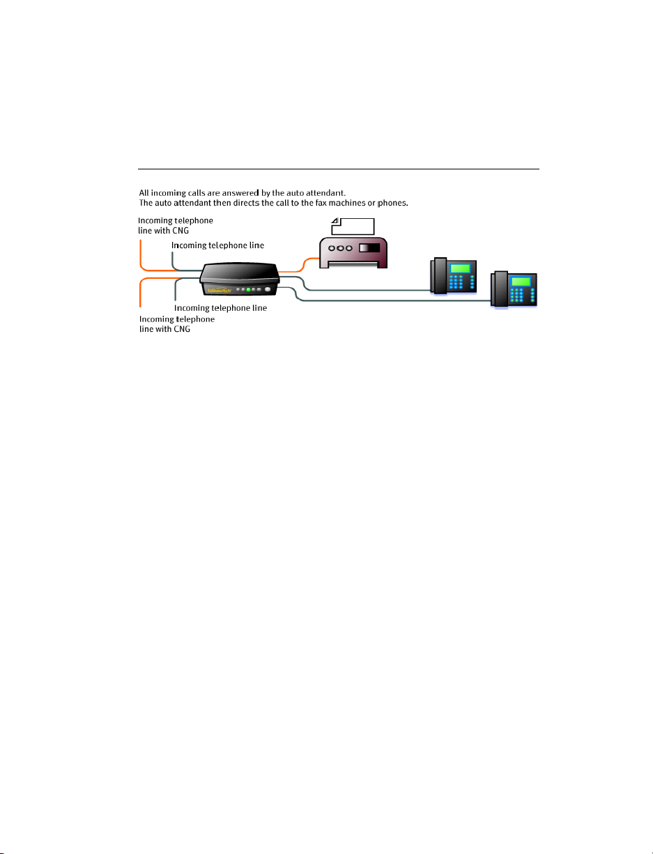
Option 3 — Automatic fax detection via the auto attendant
The auto attendant can detect incoming fax calls and route them
accordingly. To enable this, an auto attendant must answer all incoming
calls. It will listen for a fax tone (CNG) to determine if the call is an incoming
fax. If so, the call is routed to the fax machine. You must create an auto
attendant to use this method.
Figure 15: Automatic fax detection via auto attendant
Advantages: Calls are automatically handled for you. Distinctive ring service
is not required. Any telephone line can receive a fax or a call, making better
use of your resources.
Disadvantages: Some older fax machines do not emit a fax tone (CNG).
Therefore, the auto attendant cannot detect incoming faxes from those
devices. If your auto attendant volume is set too high or if your telephone
lines are noisy, the auto attendant may have difficulty detecting the
incoming fax tone and therefore not route the call to the fax machine. You
can solve this problem by adjusting the volume. For more information, see
Audio controls on page 130.
CONNECTING TO THE PA (PUBLIC ADDRESS) JACK
The PA jack can be connected to a PA system for external paging or to an
amplification system to screen voicemail or to use as a line simulator. The PA
jack requires a 1/8" (3.5 mm) mono phono connector. If you have more than
one unit connected to a LAN, you need to provide a connection onto the
system to the PA system.
SETTING UP MUSIC ON HOLD
Callers tend to react more positively to waits or transfers if they hear music.
You can also play an advertisement or provide information about your
company.
TALKSWITCH USER GUIDE 21
Page 42

External audio source
The music jack is designed to support an external audio source like a CD
player, tape player or PC media player.
Advantages: The length of the recording is not limited by the amount of
memory in the TalkSwitch units. All of the TalkSwitch memory is available
for voicemail and auto attendants. Different TalkSwitch units can have
different music on hold.
Disadvantages: Extra dedicated equipment must be connected and running
constantly. A separate sound source is required for each unit.
1. Connect the audio source via its headphone output to the music jack. Use
a cable with a 1/8" (3.5 mm) mono phono connector.
2. If your system has multiple TalkSwitch units, either use a different audio
source for each unit, or use a splitter to connect the one audio source to
each unit.
Internal audio file
You can load an audio .wav file into the TalkSwitch unit. If you have more
than one unit connected by LAN, the .wav file is automatically copied to
each unit.
Advantages: No additional equipment is required. All units use the same file,
which provides seamless music for calls transferred across the system.
Disadvantage: The length of the recording is limited by the amount of
memory in the TalkSwitch units. Less time is available for voicemail and auto
attendants.
The recording time for internal music on hold, voicemail, and the auto
attendants is two hours per TalkSwitch unit. You can expand the built-in
memory using memory cards.
NETWORKING TALKSWITCH UNITS ON A LAN
Up to four units can be networked together over a LAN to increase the
number of telephone lines and extensions in your phone system.
Connecting TalkSwitch units to a LAN
You can plug your unit(s) into your existing LAN or operate it on its own
LAN with an Ethernet switch. Ensure that the firmware on all units is
updated before adding them to the LAN.
22 TALKSWITCH INSTALLATION
Page 43

Check www.talkswitch.com/support for the latest updates.
TalkSwitch unit enclosures are not designed for stacking. We recommend
wall-mounting units to maximize airflow and keep the units from
overheating.
Ethernet switch
A switch provides direct communication between units, thus keeping the
voice-over-LAN data isolated from other data on the network.
1. Connect up to four units to the LAN switch.
2. Connect a computer to the phone system using the LAN connection or
directly to the unit through the USB or LAN port.
3. Power up and configure your units before adding any IP extensions that
will be part of the system. It is important that you place the IP
extensions on the same subnet as TalkSwitch.
Example: If your TalkSwitch unit has the IP address 192.168.1.200, your IP
extension should use IP addresses in the range 192.168.1.xxx that do not
conflict with other IP addresses.
Figure 16: Three units connected via a switch
MUSIC PA
MUSIC PA
E5 E6 E7 E8
E1 E2 E3 E4
E5 E6 E7 E8
E1 E2 E3 E4
L4L3
PF
L1
L2 USB POWER
L4L3
PF
L1
L2 USB POWER
E5 E6 E7 E8
MUSIC PA
LAN
LAN
Reset
1Internet 234
E1 E2 E3 E4
POWER
L4L3
PF
L1
L2 USB POWER
LAN
Power up all the TalkSwitch units
Connect the provided AC adapters to each unit and plug the adapters into
available power outlets. Turn the units on by pressing the Power button on
the front of each unit. The lights on the front panels of the units will flash.
This means that they are powered up and connected to the LAN, but their ID
numbers are not set.
TALKSWITCH USER GUIDE 23
Page 44

Setting or changing the unit ID
Units are shipped from the manufacturer with unit ID 1. If two or more units
are placed on the same LAN with the same unit ID number, it causes a
conflict. The four line lights on the front panel of each unit will start
flashing. You have to assign a different unit ID to each unit.
To change the unit ID, the TalkSwitch configuration software must be
closed!
1. Close the TalkSwitch configuration software.
2. Connect a standard phone to one of the extension jacks on the unit.
3. Press to enter command mode.
4. Enter a password if prompted.
5. Now, you have the following options:
Keys Result
00 Responds with the unit ID number of that particular
unit.
01 Sets the unit ID to 1.
02 Sets the unit ID to 2.
03 Sets the unit ID to 3.
04 Sets the unit ID to 4.
The system indicates that the update was successful and the front panel
lights stop flashing after a few seconds. When the front panel Data light is
on solid, the units are ready for network use.
How unit IDs affect system extension numbers
After successfully changing each unit ID to a unique number, it can be
identified by the network. More importantly, each local extension, remote
extension, and voice mailbox has a unique number.
Unit ID 1 Unit ID 2 Unit ID 3 Unit ID 4
Local extensions
(analog / IP)
24 TALKSWITCH INSTALLATION
111–118 121–128 131–138 141–148
Page 45

Local extensions
(IP only)
151-158 161-168 171-178 181-188
Remote
210-219 220-229 230-239 240-249
e x t e n s i o n s
Local
m a i l b o x e s
Remote
111-118
151-158
121-128
161-168
131-138
171-178
141-148
181-188
210-219 220-229 230-239 240-249
m a i l b o x e s
General
410-419 420-429 430-439 440-449
m a i l b o x e s
Keep track of the lines and extensions
To keep track of the extensions and telephone lines connected to each unit,
label each unit with its unit ID. It simplifies matters when you need to add
or remove extensions and lines.
If the units are located in a room away from the extensions and you need to
identify the units, the View System Information utility in the TalkSwitch
configuration software allows you to identify each unit as follows:
1. Open the TalkSwitch configuration software.
TALKSWITCH USER GUIDE 25
Page 46

2. Click the View System Information link below the TalkSwitch image.
3. Select the Unit ID to verify.
4. Click the Identify button and observe the flashing LEDs. The lights stop
flashing when you click the Close button or when 5 minutes have
elapsed.
Optimizing the system for networked use
TalkSwitch units have been designed to operate optimally when in a
networked state. Below are a few items that have been designed for better
network use.
Configuration settings
All units are cloned with identical settings. If a unit has disappeared off the
network (adapter unplugged, LAN disconnected, LAN failure, etc.), the
system can still handle the calls since it retains the configuration settings of
the missing unit. If an extension or a voice mailbox cannot be reached, the
caller hears a system prompt: “The extension you are trying to reach is
currently unavailable, please try again later.”
Outgoing line hunt groups
When two or more units are on a LAN, the system tries placing calls out on
the same unit the call originates from. This avoids using a line across the
LAN on another unit, which helps to minimize the LAN traffic and optimizes
the opportunity for all inbound calls to connect across the LAN if required.
Auto attendants
There are a total of nine auto attendants that are shared by all units on the
LAN. When an auto attendant is recorded on any unit, it is automatically
copied to all other units on the LAN. This design minimizes LAN traffic and
provides functionality back-up in case a unit or units have disappeared off
the network (adapter unplugged, LAN disconnected, LAN failure, etc.). In
this event, all units can still answer inbound calls with the same auto
attendant messages.
26 TALKSWITCH INSTALLATION
Page 47

Voicemail
All local extension and remote extension voicemail data is stored on the unit
that the extension is connected to. For example, all greetings, directory
names and voicemail messages for extensions 121-128, 220-229 and
mailboxes 420-429 are stored on unit 2. If a unit is completely filled with
voicemail messages, the system will not accept any more messages for its
extensions. However the other units will accept messages for their
extensions. If you need more memory, TalkSwitch memory cards can be
purchased from your reseller. To view the memory usage of each TalkSwitch
unit and each mailbox, choose Tools > Memory Usage > Voicemail or
choose Tools > Voicemail Manager.
Special considerations when connecting multiple units to a LAN
Each unit is identified with a tab at the top of the configuration window, as
shown in the following illustration.
Multiple TalkSwitch units on a LAN will function as a single phone system.
Some features are expanded as you add units, and other features are not.
As you add more units, the number of telephone lines, local extensions, VoIP
lines, remote extensions and voice mailboxes will increase.
For example, if you have a 480vs and a 244vs connected on the same LAN,
the system can support 6 telephone lines, 32 local extensions, 4 VoIP lines,
20 remote extensions, 32 local voice mailboxes, 20 remote voice mailboxes,
and 20 general voice mailboxes.
The features listed below are not affected by the number of units on the
LAN, so capacity will not increase as you add units.
Feature Description
Auto
There are nine auto attendants.
Attendant
Ring Groups There are ten ring groups (300-309).
Park Orbits There are ten park orbits (500-509).
TALKSWITCH USER GUIDE 27
Page 48

Music on
Hold
Public
Address (PA)
You can add music on hold to your system by loading an
internal music file. The music file is copied to each TalkSwitch
unit, so the music on hold will be the same for each line of
each unit.
Each unit has a PA output for connection to a public address
system. The PA output for a TalkSwitch unit is only accessible
from extensions connected to that unit. To connect all outputs
to a single amplifier, you will require an adapter.
INCREASING MEMORY CAPACITY
The recording time for internal music on hold, voicemail, and the auto
attendants is two hours per TalkSwitch unit. You can expand the built-in
memory using memory cards. Contact your reseller to purchase memory
upgrades.
TalkSwitch memory cards
TalkSwitch memory cards are specifically formatted for use with TalkSwitch
units. They allow you to add additional voicemail message capacity to your
unit. Voicemail memory is used to store messages left in voice mailboxes. It
is also used to store auto attendant greetings and announcements.
Figure 17: Memory card
Installing a memory card
1. Insert the memory card into the memory slot with the gold contact face
down and the “This side up” label showing. You don’t have to turn the
unit off or disconnect any of the telephones.
2. Ensure the Total Unit Time has increased in the Mailbox Data window.
See Viewing mailbox data on page 92.
28 TALKSWITCH INSTALLATION
Page 49

Figure 18: Memory card slot
UPGRADING TALKSWITCH UNITS
As your business grows, your TalkSwitch unit(s) may need upgrading. You
have the option of upgrading your units to VoIP, as well as adding telephone
lines and extension jacks. The upgrade kit consists of a top board that you
add to your existing TalkSwitch unit, as well as a guide containing detailed,
step-by-step instructions for the upgrade procedure.
Purchase VoIP modules and upgrade boards at your reseller. Visit http://
www.talkswitch.com/products/upgrades_accessories.asp on the TalkSwitch
web site for more details.
Note that in some cases it may be easier and more cost effective to buy
another TalkSwitch unit than to upgrade an existing unit.
Upgrade TalkSwitch
Unit
Add four VoIP
lines
Add eight VoIP
lines
TALKSWITCH USER GUIDE 29
240vs
280vs
480vs
840vs
48-CA
240vs
280vs
480vs
840vs
48-CA
Board TalkSwitch
Equivalent
4plus 244vs
284vs
484vs
844vs
48-CVA
8plus 248vs
288vs
488vs
848vs
48-CVAv2
Page 50

Upgrade TalkSwitch
Unit
Board TalkSwitch
Equivalent
Add six
telephone lines
Add four
extension jacks
Add two
telephone lines
and four
extension jacks
240vs
244vs
248vs
240vs
244vs
284vs
240vs
244vs
248vs
24-CA
600plus 840vs
844vs
848vs
40plus 280vs
284vs
288vs
240plus
24-CA to 48-CA
top board
480vs
484vs
488vs
48-CA
ENABLING LICENSED ADD-ONS
It is possible to enable the following features on your TalkSwitch:
• Attendant Console software
For instructions on enabling TalkSwitch licensed add-ons, see Licensed add-
ons on page 142.
VERIFYING THE CONNECTIONS
If you are having problems, they could be due to loose cables. Check the
following:
1. Are your telephone cables connected to a wall jack at one end and the
unit at the other? Ensure the devices you are using as extensions
(telephones, faxes, etc.) are plugged into the extension jacks located on
the back panel of the unit. Do not plug your extensions directly into a
wall jack unless that jack is wired to a unit extension jack.
2. Check the USB or LAN connection between TalkSwitch and your PC.
3. Ensure that the unit AC adapter is plugged into a working power outlet
and that the unit is turned on. Make sure that you are using the AC
adapter supplied with your unit. This adapter cannot be substituted with
any other adapter. If your adapter appears to be defective, please contact
your TalkSwitch dealer to order the proper replacement.
30 TALKSWITCH INSTALLATION
Page 51

If networked, ensure that you have the latest firmware loaded on all units.
To check the firmware version, open the TalkSwitch configuration software,
and click the link View System Information. All units listed in the System
Information window should have the same firmware version.
CONNECTING A TALKSWITCH UNIT TO A PBX
Connecting a TalkSwitch unit to a PBX allows the TalkSwitch unit to answer
calls with an auto attendant. The caller can dial 7 followed by an extension
number to reach an extension on the PBX.
1. Connect one or more PBX extensions to the TalkSwitch telephone line
jacks (one PBX extension per line).
2. Configure the PBX to route incoming calls to the PBX extensions that are
connected to the telephone line jacks of the TalkSwitch unit.
3. Configure the auto attendant to answer after a specified number of rings.
4. Record the auto attendant messages. They should list the extensions
with the digit 7 in front of them.
For example, if you have chosen the PBX extension length to be 3 digits and
John Smith’s extension is 111 on the PBX, the auto attendant should say:
“To speak with John Smith, dial 7111.” When the caller dials 7111, the
TalkSwitch unit puts the caller on hold and transfers them to extension 111
on the PBX.
TALKSWITCH USER GUIDE 31
Page 52

LOADING A CONFIGURATION FILE
You can load the latest configuration file saved on a PC to make edits and
save it again as a file or save it directly to TalkSwitch.
1. Double-click the TalkSwitch icon on your desktop to open the TalkSwitch
configuration software. The window below displays.
2. From the drop-down list next to Connection Type, select File.
3. Click the Browse button, select the configuration file you wish to open,
and then click Open.
4. Click Connect....
32 TALKSWITCH INSTALLATION
Page 53

5. The TalkSwitch System Configuration window opens.
When a unit is being configured, it is locked to prevent other computers
or persons using a phone from configuring changes at the same time. If
you leave the software open for longer than one hour, the unit unlocks
itself to allow configuration changes.
Restoring firmware
The Restore Firmware button updates firmware if an update attempt has
failed. Click the Restore Firmware button, then select which firmware file to
load onto the unit. The firmware update will then begin. Follow the
instructions presented at each step. Progress will be displayed as the update
proceeds.
If you are downgrading to an earlier firmware version, and have more than
one networked TalkSwitch unit, you must perform the Restore Firmware one
unit at a time, with the unit separated from the network during the restore.
TALKSWITCH USER GUIDE 33
Page 54

Page 55

CHAPTER 2
Chapter 2: TalkSwitch Config uration
TALKSWITCH CONFIGURATION
INTRODUCTION
This chapter contains detailed information about all the features in the
TalkSwitch configuration software with step-by-step instructions on how to
customize these features to best suit your needs.
Context-sensitive help information is available for each option in the
TalkSwitch configuration software. Rest your mouse cursor over any of the
controls and the information related to that control displays in a pop-up.
TALKSWITCH USER GUIDE 35
Page 56

TALKSWITCH SYSTEM CONFIGURATION WINDOW
The following illustration shows the TalkSwitch System Configuration
window.
X
Z
Y
[
\
The numbers are explained below.
1 Menu commands.
2 Configuration navigation controlling the display in the configuration
window.
3 Configuration window displaying configuration information.
4 View System Information is a link to the MAC address, IP address,
hardware and firmware version of the unit.
View Mailbox Data is a link to the time usage by voicemail, auto
attendants, and music-on-hold.
Adjust Date/Time is a link to set the time, date, time zone, and NTP
server.
5 Region shows the location where TalkSwitch is intended to operate
36 TALKS W I TCH CONFIGURATION
Page 57

MENU COMMANDS
File menu
Open... Opens the existing configuration files from the PC.
TalkSwitch backs up the configuration to a file called
Configuration every time you save the settings.
Save to
TalkSwitch
Save to File... Saves the current configuration to a file on your PC.
Retrieve
Settings
Update
Firmware...
Exit Closes the TalkSwitch configuration software.
View menu
Toolbar Toggles the toolbar on and off.
Status Bar Toggles the status bar on and off.
Saves the current configuration to the TalkSwitch
unit. New settings must be saved to the TalkSwitch
unit to take effect. A progress bar will show the data
exchange to the TalkSwitch unit. It takes only a few
seconds to complete.
Retrieves the settings from the unit connected to the
PC.
Updates the firmware. For more information, see
Upgrading the TalkSwitch software and firmware on
page 7.
Tools menu
Memory Usage
> Voicemail
Memory Usage
> Auto
Attendant
Voicemail
Manager
Terminal
Window
TALKSWITCH USER GUIDE 37
Displays a window showing internal memory usage for
voicemail messages.
Displays a window showing internal memory usage for
auto attendant messages.
Displays a window with options to check the voice
mailbox data, delete a mailbox password and reset
mailboxes to factory default.
Displays a command line interface. This option is
useful for troubleshooting in conjunction with
technical support.
Page 58

Call Logging
Output
Defaults... Resets the current page or the entire configuration to
Reboot
TalkSwitch
Check for
updates
A TalkSwitch unit can store call detail records, or can
output them to a PC in real-time. View the call detail
records using the Call Reporting licensed add-on
application, or a web browser.
defaults.
Prompts you to save the configuration and provides
options when to reboot.
Checks the web site for TalkSwitch configuration
software updates.
Help menu
Help
Documents...
Support on the
Web...
About
TalkSwitch
Configuration
Utility...
Opens the folder containing the TalkSwitch
documentation.
Launches your browser and links you to our support
site.
Displays the TalkSwitch software version number,
firmware version and copyright information.
CONFIGURATION NAVIGATION
The configuration navigation organizes all the configuration topics within
folders.
Click the sign beside each folder to expand it and display configuration
option sub-categories. When you configure TalkSwitch or when you wish to
modify the setup, it is helpful to be familiar with this structure.
The following is a brief description of each folder seen in the navigation
section to the left of the window.
About
TalkSwitch
System
Information
Display version information about the TalkSwitch
software, the number of new voicemail messages, the time
and date, and the current mode.
Configure the system setup. From here you can activate
telephone lines and extensions.
38 TALKS W I TCH CONFIGURATION
Page 59

Voicemail Configure voice mailboxes and global settings for the
voicemail system.
Call
Handling
Call Back/
Call Bridge
Options Configure permissions, audio controls, transfer options,
Licensed
Add-Ons
Configure how to handle incoming calls. It includes auto
attendant and individual call handling setups for
telephone lines, extensions and modes of operation.
Configure call back/call bridge (DISA) to reduce your
company’s long-distance expenses.
miscellaneous and system timing settings.
Enable applications like Attendant Console.
SYSTEM ADMINISTRATION
System Administration contains the following items:
• Administration
• IP Configuration
• VoIP Configuration
• Telephone Lines
• VoIP Numbers
• Line Hunt Groups
• Automatic Route Selection
• Fax Information
• Local Extensions
• Remote Extensions
• Extension Ring Groups
• On-Hold/Ringback
Some of the configuration screens vary depending on whether multiple
TalkSwitch units are networked.
The VoIP Configuration and VoIP Numbers pages are only present if a
TalkSwitch unit has VoIP lines.
TALKSWITCH USER GUIDE 39
Page 60

ADMINISTRATION
The System Information > Administration page allows you to set up the
system name, system password, caller ID for outgoing VoIP calls, language,
and localization settings (depending on the region).
For security reasons, we recommend that you use password protection at the
administrator level. The password is entered at configuration start-up and
when you access the configuration through an extension phone.
Change the password frequently to prevent unauthorized users from
making calls or changing the configuration.
1. Expand System Information > Administration.
2. Enter a name in the System Name box. If you have multiple units, we
recommend that you assign a system name to each unit for tracking
purposes. You will require the system name when logging in through the
web interface for status or call detail record (CDR) information.
40 TALKS W I TCH CONFIGURATION
Page 61
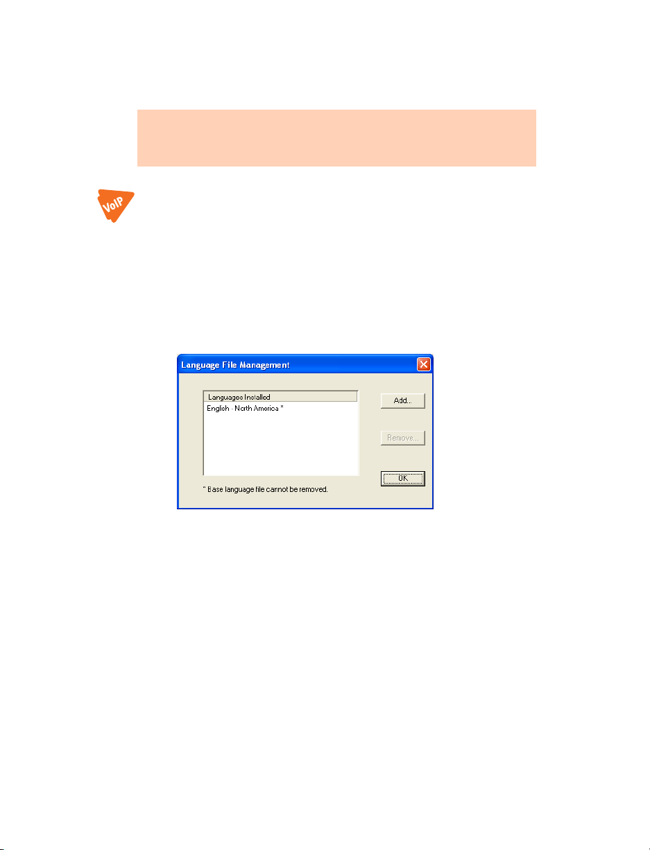
3. Enter a system password in the System Password box. It has to be a 4- to
8-digit numeric password, so that you can also enter it on a touchtone
phone.
Caution: If you leave the System Password box blank and are connected
to the internet with TCP/IP port 9393 mapped to the unit, the system will
be vulnerable to configuration changes by anyone on the internet.
4. Set the caller ID information for outgoing VoIP calls:
• To use the System Name, select Use System Name in Caller ID
information for all outgoing VoIP calls.
• To use the First Name and Last Name set up for each local extension,
select Use Extension Names in Caller ID information for all outgoing
VoIP c alls.
5. To load a different language into the TalkSwitch system:
a) Click Edit. The Language File Management window appears.
b) Select the language, and then click OK. The TalkSwitch configuration
software will show the selected language.
6. Select the language for prompts heard by callers in the Select the default
language list.
TALKSWITCH USER GUIDE 41
Page 62

IP CONFIGURATION
The System Information > IP Configuration page allows you to set up the
IP configuration.
1. Expand System Information > IP Configuration.
2. Set whether the system should automatically get system IP settings
using DHCP (dynamic host configuration protocol).
• To get system IP settings using DHCP, select Obtain IP and DNS
information automatically. This is the default method, but requires a
DHCP server.
If you use a DHCP server, you have to reserve an IP address for each
TalkSwitch unit. To reserve an IP address, you need the MAC address
of each unit. To view the MAC address, click the View System
Information link on the About TalkSwitch page.
• To set system IP settings manually, select Use the following IP and
DNS information.
3. If you selected Use the following IP and DNS information, enter the
system IP settings.
a) Enter a static IP address for each TalkSwitch unit in the Unit IP
Address boxes.
42 TALKS W I TCH CONFIGURATION
Page 63

b) Enter the Subnet mask for the LAN. This address determines what
subnet the unit IP addresses belong to.
c) Enter the IP address of the Default Gateway on your network. A
gateway is a hardware device (i.e. router) that connects the office
network to the Internet.
d) Enter the IP address of the Preferred DNS Server. DNS is a service that
is used to resolve a domain name to an IP address.
e) If applicable, enter the IP address of the Alternate DNS Server.
4. If your TalkSwitch system has multiple TalkSwitch units, set the
TalkSwitch unit that will act as local proxy.
a) Click the Change... button. The TalkSwitch window appears.
b) Select the TalkSwitch unit, and then click Change.
5. Set up the Public WAN IP Address.
a) Set the Type of public WAN IP address for Internet Connection.
• To have the TalkSwitch unit check its public IP address every five
minutes, select dynamic. If the public IP address changes, the
TalkSwitch unit automatically uses the new one. This allows the
TalkSwitch unit to manage VoIP calls properly.
• If the TalkSwitch unit is within a closed network environment,
select static.
b) If you selected dynamic, enter the Public WAN IP address-checker
server name. The default server is checkip.talkswitch.com. This
server runs an IP checker application that provides public IP
addresses to TalkSwitch units.
TALKSWITCH USER GUIDE 43
Page 64

c) If you selected static, enter the Current public WAN IP address. This is
the static public IP address from your service provider. If the
TalkSwitch unit is not behind a router, this is the IP address of the
TalkSwitch unit that is acting as the local proxy.
d) Enter the Fully Qualified Domain Name (FQDN) if this location acts as
the SIP server and uses a dynamic public IP address. You can obtain
FQDNs for free at www.dyndns.org.
If your router supports DDNS, program the required information to
update the DNS servers. If not, download one of the applications
specified on the site. It needs to run on a PC connected to the same
LAN to update the DNS servers.
If the unit is enabled as a SIP server and no FQDN was entered, the
following prompt appears.
TELEPHONE LINES
The System Information > Telephone Lines page allows you to set up the
main number, distinctive ring 1 number, distinctive ring 2 number, and
telephone company services for each telephone line. After adding or
changing a line, you can calibrate the telephone lines.
The distinctive ring service provides one or two additional phone numbers to
the telephone line. Each phone number causes a different ring pattern. You
can set up separate call handling for the main number, distinctive ring 1
number, and distinctive ring 2 number.
• Main number corresponds to the normal ring pattern.
• Distinctive ring 1 corresponds to a double ring pattern.
• Distinctive ring 2 corresponds to a triple ring pattern.
44 TALKS W I TCH CONFIGURATION
Page 65

Setting up telephone lines
1. Expand System Information > Telephone Lines.
2. Select a telephone line tab.
3. Select the Activate line check box.
4. Check whether the TalkSwitch unit has detected the telephone line. The
TalkSwitch unit first attempts to detect telephone lines during
initialization. It tries again when the TalkSwitch configuration software
retrieves the configuration from the TalkSwitch unit.
• Line Detected appears if the telephone line was detected when the
configuration was last retrieved.
• Line detected at initialization: No appears if the telephone line was
not detected.
5. If the line detection status is Line detected at initialization: No then
detect the line.
a) Check the physical connection of the telephone line to the
TalkSwitch unit.
b) Choose File > Save to TalkSwitch to save the configuration.
Alternatively, you can click the Save settings to TalkSwitch icon.
TALKSWITCH USER GUIDE 45
Page 66

c) Choose File > Retrieve Settings to update the line detection status.
Alternatively, you can click the Retrieve settings from TalkSwitch
icon.
6. Enter the phone number of the telephone line in the Main number box.
7. If the telephone line has the distinctive ring service, and you want to set
up different call handling for the distinctive ring numbers, select the
Distinctive Ring 1 and Distinctive Ring 2 check boxes. If you want the
same call handling for the main number and the distinctive ring
numbers, clear the check boxes.
8. If you selected the Distinctive Ring 1 and Distinctive Ring 2 check boxes,
enter the distinctive ring numbers. The distinctive ring numbers will
appear in the Call Handling > Telephone Lines page.
9. Select the Telephone Company Services that are active on the telephone
line. See Appendix B: TalkSwitch and Telephone Company Calling
Services for a description of these services and how the TalkSwitch unit
uses them.
• 3-Way Calling/Conference allows the same line connect feature to
work with the line’s 3-way calling and conferencing service for call
bridge (DISA) calls, and with incoming calls that are routed to remote
extensions.
• Transfer and Clear (Centrex/Plexar transfer) allows the TalkSwitch
unit to release the line when it is no longer required for a remote
extension call. Enable this feature if the line’s 3-way calling/
conference service will allow a call to remain in progress between
other parties if the system hangs-up on the conference call. Enabling
this feature without the service will result in incoming callers being
disconnected when their call is forwarded to a remote extension.
• Call Waiting is generally not recommended, since it is difficult to
answer a second call on the same line. For applications with more
than one line consider using the telephone company’s hunting
facility or call forward on busy service.
• Caller ID allows the TalkSwitch unit to forward caller ID information
to the local extensions. The TalkSwitch unit can also use the time
information provided by caller ID to update its internal clock.
• Telephone Company Voicemail allows a voicemail service to be
activated on the line.
46 TALKS W I TCH CONFIGURATION
Page 67

• Hunt/Rollover/Busy Forwarding indicates the line has a hunting
facility or call forward on busy service.
Calibrating telephone lines
Calibration optimizes transmission for the type of telephone line or
equipment connected to the TalkSwitch unit. Calibration improves
performance for call bridge (DISA) and call forwarding.
You should calibrate the lines:
• After adding or changing a telephone line.
• After connecting a line to equipment other than a telephone company
line.
• If poor audio performance is encountered.
Only telephone lines that have been detected will be calibrated.
1. Click the Calibrate Lines button. The Choose Line to Calibrate window
appears.
2. If required, click the Refresh Lines button to detect the lines.
3. Select the Line check boxes associated with the line(s) to calibrate, and
then click OK.
TALKSWITCH USER GUIDE 47
Page 68

LINE HUNT GROUPS
The System Information > Line Hunt Groups page allows you to set up the
name, line type, and set of telephone lines or VoIP lines for each line hunt
group.
Ensure that line hunt group 9 allows access to telephone lines that can
reach emergency services.
A line hunt group is a set of telephone lines or VoIP lines for making an
outbound call. The user dials the line hunt group number. The TalkSwitch
unit hunts through the lines in the group, which are arranged in a certain
order, and uses the first line that is available.
You can set up nine different line hunt groups. The TalkSwitch unit uses a
line hunt group when placing a call from a local extension, to a remote
extension, or with the call bridge (DISA) feature. You can restrict the line
hunt groups that a local extension can use, in order to reserve telephone
lines for high-priority users.
Instead of a set of telephone lines, a line hunt group can include the VoIP
lines associated with the TalkSwitch profile, or the VoIP lines associated with
the service provider profile. As described previously, the user dials the line
hunt group number when placing an outbound call. However the line hunt
group contains VoIP lines, and you cannot arrange them in a certain order.
The line hunt groups do not affect incoming calls.
The TalkSwitch system has the following line hunt groups by default. The
system will first search the higher line numbers (e.g. line 4) for outgoing
calls, since the lower line numbers are more heavily used for incoming calls.
You can modify the default line hunt groups as required.
Hunt Group 9 Selects line 4, line 3, line 2, then line 1.
Hunt Group 81 Selects line 1.
Hunt Group 82 Selects line 2.
Hunt Group 83 Selects line 3.
Hunt Group 84 Selects line 4.
Hunt Group 85 - 86 No lines are assigned.
48 TALKS W I TCH CONFIGURATION
Page 69

Hunt Group 87 If the TalkSwitch unit has a VoIP module, and a
VoIP service provider is configured, selects an
available VoIP line from those associated with the
VoIP service provider. If the TalkSwitch unit does
not have a VoIP module, or if no VoIP service
provider is configured, no lines are assigned.
Hunt Group 88 If the TalkSwitch unit has a VoIP module, selects an
available VoIP line from those associated with the
TalkSwitch VoIP network. If the TalkSwitch unit
does not have a VoIP module, no lines are assigned.
1. Expand System Information > Line Hunt Groups.
2. Select a line hunt group tab.
3. Enter a name in the Label box. The name will identify the line hunt
group elsewhere in the TalkSwitch configuration software.
4. Set the Line Type.
• To access telephone lines, select Phone Lines.
• To access TalkSwitch VoIP lines, select TalkSwitch VoIP Numbers.
TALKSWITCH USER GUIDE 49
Page 70

• To access service provider VoIP lines, select VoIP Service Provider 1
VoIP N umbers.
5. If you set Line Type to Phone Lines:
a) Add lines by selecting the adjacent check boxes.
b) Change the order of the lines by selecting a line, and then clicking
the Move Up or Move Down button.
6. If you have multiple TalkSwitch units connected to the LAN, the For all
Hunt Groups, hunt lines on the same unit first check box appears. If
selected, outbound calls will always start by hunting the lines on the
TalkSwitch unit that the extension is connected to. This minimizes
network traffic between TalkSwitch units. The check box is selected by
default, but you can disable this feature if necessary.
AUTOMATIC ROUTE SELECTION
The System Information > Automatic Route Selection page allows you to
set up automatic route selection (ARS) and toll restriction.
Enable password protection when ARS or toll restriction is used. Change
the password frequently to prevent unauthorized users from making calls
or changing the configuration. See Administration on page 40.
Introduction
Automatic route selection
Automatic route selection (ARS) routes outgoing calls to a certain line hunt
group depending on the leading digits. It can also prefix phone numbers
with certain carrier codes depending on the leading digits and time of day.
This way calls can use specific telephone lines, alternative carriers, or VoIP
lines, for least-cost routing. For example, ARS can route international calls to
a VoIP service provider; national calls to an alternative carrier offering a
discounted calling plan; and calls to cellular phones on a telephone line that
is connected to a fixed wireless terminal for cellular-to-cellular calling.
If the user dials a line hunt group number, ARS can override the selection
and use a different line hunt group depending on the leading digits.
50 TALKS W I TCH CONFIGURATION
Page 71

Toll restriction
Toll restriction blocks outgoing calls based on the leading digits. For
example, toll restriction can block calls to inappropriate or premium rate
services.
Leading digits
The leading digits are the first numbers dialed when placing a telephone call.
The leading digits could be an international access code, country code,
national code, STD code, area code, leading digits of premium rate service
codes, or phone number.
The leading digits used in each country are subject to the national
numbering plan. Your telephone directory will provide information on the
numbers used.
Calls with leading digits that do not match the entries in the ARS table will
be routed to the line hunt group originally dialed by the caller.
ARS and toll restriction act on the longest leading digits entry matching the
dialed number. For example, an entry in the ARS table blocks numbers with
leading digit “1” to prevent long-distance calls. However a second entry
routes numbers with leading digits “1800” through a line hunt group
because they are toll-free. Because the second entry (1800) is longer than
the first entry (1), the second entry has precedence. Therefore a call with
leading digits “1800” is routed, even though leading digit “1” would
otherwise cause it to be blocked. This technique can reduce the number of
entries required in the ARS table; and can be used to restrict calls to all but
specific area codes or countries.
• Leading digits can be 1–11 numbers in length.
• Leading digits can include numbers 0–9.
• The leading digits exclude the line hunt group number dialed by the user.
Carrier codes
A carrier code is prefixed to the phone number dialed by the user. It tells the
telephone line service provider to route the call to an alternative carrier. For
example, the carrier code could be a calling card number and PIN number.
ARS determines the carrier code based on the leading digits and the time of
day.
• Carrier codes can be up to 1–24 characters in length.
TALKSWITCH USER GUIDE 51
Page 72

• Carrier codes can include numbers 0–9, “*” (asterisk), “#” (pound), “,”
(comma for 2-second pause), and “w” (for wait-for-dial-tone). A 2second pause is automatically added after dialing a carrier code.
An entry in the ARS table can have one or two carrier codes. Carrier Code 1 is
either used all day, or from Start Time 1 until Start Time 2. Carrier Code 2 is
used from Start Time 2 until Start Time 1.
Use of Carrier Selection Prefix and Carrier Codes may require subscription to a
carrier’s discount calling plan. This service may not be available in some
countries and on some telephone companies’ telephone lines. Carrier
Selection Prefix may not be required if a “Pre-Selection” service is provided
by the telephone line service provider.
Planning automatic route selection and toll restriction
1. Identify the leading digits of calls to be blocked by toll restriction.
2. Identify the leading digits of calls to be routed by ARS.
3. Identify which telephone lines and VoIP lines are connected to different
service providers.
4. Assign telephone lines and VoIP lines to line hunt groups, in order to
provide separate access to each different service provider.
5. Identify carrier codes, which leading digits they work with, and when
they will be used.
6. Provide local extensions with access to line hunt groups. This controls
how local extensions have calls routed by ARS or blocked by toll
restriction.
Direct line access
When Direct Line Access is enabled on a local extension, the user does not
have to dial a line hunt group number. Calls placed from that local extension
are automatically routed to a designated line hunt group. If ARS is enabled
on the designated line hunt group, the calls are subject to ARS and toll
restriction.
3-Way Calling/Conference service
The use of the telephone company‘s 3-Way Calling/Conference service is not
recommended on telephone lines when ARS or toll restriction are used. The
system’s ARS and toll restriction features do not have any control over the
routing of calls through these telephone company services.
52 TALKS W I TCH CONFIGURATION
Page 73

Emergency service numbers
The telephone numbers in the Emergency Service Numbers area will not be
blocked by toll restriction nor redirected by ARS. Calls to these telephone
numbers will be routed through line hunt group 9.
Enter any other local emergency service numbers into the ARS table to
ensure that calls are routed to a line hunt group with telephone lines that
provide access to emergency services.
Inter-Digit Timeout (IDT)
ARS and toll restriction are implemented on each call when the longest
matching entry is found in the ARS table or after the inter-digit timeout
period. The default inter-digit timeout is set to 5 seconds. If required,
change the inter-digit timeout. See Troubleshooting on page 136.
To complete a dialed number before the inter-digit timeout expires, the user
can press .
Setting up automatic route selection and toll restriction
1. Configure the administrator password and line hunt groups before setting
up ARS and toll restriction.
2. Expand System Information > Auto Route Selection.
TALKSWITCH USER GUIDE 53
Page 74

3. Select the Activate Automatic Route Selection check box.
4. Enter the leading digits in the Leading Digits box.
5. Select the Action. Choices are:
• Hunt Group (n) — Performs ARS by routing the call to the line hunt
group.
• Block Calls — Performs toll restriction by blocking the call.
6. If required, set up the carrier code(s).
a) If the route requires one carrier code for the whole day:
i) Enter the carrier code in Carrier Code 1.
ii) Select the All Day check box.
b) If the route requires one carrier code for part of the day:
i) Enter the carrier code in Carrier Code 1.
ii) Enter Start Time 1.
iii) Enter Start Time 2.
c) If the route requires two carrier codes, one for each part of the day:
i) Enter the first carrier code in Carrier Code 1.
ii) Enter Start Time 1.
iii) Enter the second carrier code in Carrier Code 2.
iv) Enter Start Time 2.
54 TALKS W I TCH CONFIGURATION
Page 75

7. To select the line hunt groups that are subject to ARS and toll restriction,
click ARS Hunt Groups. The ARS Hunt Groups window appears.
8. Select the Hunt Group check boxes. The selected line hunt groups will be
subject to ARS and toll restriction.
If a telephone line has the 3-Way Calling/Conference service, the Hunt
Group 80 is used for Same Line Connect check box is enabled. If the check
box is selected, and a remote user enters line hunt group 80 to activate
call bridge, the same telephone line will be used to place the call (instead
of a telephone line chosen by ARS). However toll restriction will still be
used.
Restricting local extension access to line hunt groups
By default, all local extensions have access to all line hunt groups. As part of
an ARS and toll restriction scheme you can restrict the line hunt groups that
a local extension can use. If the user dials leading digits that route the call
to a line hunt group, and the user does not have permission to use that line
hunt group, then the call is blocked.
1. Remove the local extension’s access to the line hunt group. See Setting
line hunt group permissions on page 67.
Allowing a local extension to bypass ARS and toll restriction
You can allow a local extension to select a line hunt group that bypasses ARS
and toll restriction. The user will be able to dial any phone number, and no
carrier codes will be prefixed to the phone number.
TALKSWITCH USER GUIDE 55
Page 76

1. Set up a line hunt group with telephone lines or VoIP lines. See Line
Hunt Groups on page 48.
2. Provide the local extension with access to the line hunt group. See
Setting line hunt group permissions on page 67.
3. Expand System Information > Auto Route Selection.
4. Click ARS Hunt Groups. The ARS Hunt Groups window appears.
5. Clear the associated Hunt Group check box. The line hunt group will not
be subject to ARS and toll restriction.
Regulatory advisory notice
Call Redirection & Service Provider Billing Advisory
Use of the automatic route selection, toll restriction and call detail
recording features does not imply any guarantee whatsoever by
regulatory authorities, your telephone service provider(s), TalkSwitch or
its distributors and resellers, with regard to the accuracy of these features
and that the use of such a features may not be considered by a telephone
company in any disputes which may arise regarding the accuracy of any
subscriber's telephone account.
FAX INFORMATION
The System Information > Fax Information page allows you to set up the
connection to the fax machine, including its phone number and extension
number. This information is required if using the distinctive ring fax
detection option.
TalkSwitch provides you with different options to connect your fax machine.
The options are dedicated fax line, distinctive ring fax detection, and
automatic fax detection. See Connecting a fax machine on page 19 for a
description of each option.
56 TALKS W I TCH CONFIGURATION
Page 77

Setting up a dedicated fax line
1. Expand System Information > Fax Information.
2. Set the Fax number list to None.
3. Set the Extension number list to None.
Setting up distinctive ring fax detection
1. Expand System Information > Telephone Lines.
2. Select the telephone line tab of the telephone line used by the fax
machine.
3. Select the Activate line check box.
TALKSWITCH USER GUIDE 57
Page 78

4. In the Main number box, enter the phone number that people dial to call
your office.
5. Select the Distinctive Ring 1 check box, and enter the distinctive ring
phone number that people dial to fax your office.
6. Expand System Information > Fax Information.
7. Set the Fax number list to the distinctive ring phone number.
8. Set the Extension number list to the extension jack that the fax machine
is connected to.
58 TALKS W I TCH CONFIGURATION
Page 79

Setting up automatic fax detection
1. Expand Call Handling > Auto Attendant.
2. Select the auto attendant tab.
3. In the If a fax call is detected list, select go to local ext., and then select
the extension jack that the fax machine is connected to.
4. Repeat Steps 2 and 3 for each auto attendant that answers a telephone
line.
5. Expand System Information > Fax Information.
6. Set the Fax number list to None.
TALKSWITCH USER GUIDE 59
Page 80

7. Set the Extension number list None.
LOCAL EXTENSIONS
The System Information > Local Extensions page allows you to set up the
extension type, caller ID, phone model, direct line access, line hunt group
permissions, and line appearance (certain phones only) for each local
extension.
A local extension is an analog extension or an IP extension.
An analog extension is a device (standard phone, cordless phone, fax
machine or modem) connected to an extension jack on the TalkSwitch unit.
An IP extension can be internal or external. An internal IP extension is an IP
phone connected through the LAN to the TalkSwitch unit. An external IP
extension is an IP phone located outside the office. It is connected to the
TalkSwitch system through the internet. External IP extensions require the
TalkSwitch unit to have a VoIP module.
Each TalkSwitch unit has 16 local extensions. Either four or eight local
extensions can be analog or IP extensions, depending on the model of the
TalkSwitch unit. The remaining twelve or eight local extensions can only be
IP extensions.
All local extensions are active by default. If you plug a standard phone into
an extension jack, it will be ready to make and receive calls. However
configuration is required to set up an IP extension.
The first eight local extensions are numbered as follows:
• TalkSwitch Unit 1 — 111 to 118
• TalkSwitch Unit 2 — 121 to 128
• TalkSwitch Unit 3 — 131 to 138
• TalkSwitch Unit 4 — 141 to 148
The next eight local extensions can only be IP extensions, and are numbered
as follows:
• TalkSwitch Unit 1 — 151 to 158
• TalkSwitch Unit 2 — 161 to 168
• TalkSwitch Unit 3 — 171 to 178
60 TALKS W I TCH CONFIGURATION
Page 81

• TalkSwitch Unit 4 — 181 to 188
Setting up an analog extension
1. Expand System Information > Local Extensions.
2. Select a local extension tab.
3. Select the Activate Extension check box.
4. Select Regular Extension in the Extension Type list.
5. Enter the user’s First name and Last name. The names are used for caller
ID, and appear within the configuration windows. The Last name is used
with the dial-by-name directory.
6. Record the user’s name by picking up a handset, and then pressing
, <extension number>, 4.
7. Select the type of phone at the extension.
• If a TalkSwitch phone is connected to the extension, choose the
model. Choices are TS-80, TS-100, TS-200, TS-400 and TS-600.
TalkSwitch uses this information to configure the phone to support
the features that match the capabilities of the phone. Features
include intercom paging, group paging over the speaker, and the
message waiting counter.
TALKSWITCH USER GUIDE 61
Page 82

• If a different phone or device is connected to the extension, choose
Regular Phone, Fax or Modem.
8. Select the language for prompts heard by callers in the Prompts language
for this extension list.
9. Select the phone numbers you want to display at the remote location
when VoIP calls are placed from this extension. If Default VoIP number is
selected, the phone number associated with the outgoing VoIP port is
used. This selection makes the most sense if your VoIP numbers have
been configured to handle all inbound calls the same way.
a) Set the Phone number used for TalkSwitch VoIP Caller ID list to the
phone number displayed during a VoIP call between TalkSwitch units.
b) Set the Phone number used for Service Provider Caller ID list to the
phone number displayed during a VoIP call through a service
provider.
Setting up an IP extension
1. Expand System Information > Local Extensions.
2. Select a local extension tab.
3. Select the Activate Extension check box.
62 TALKS W I TCH CONFIGURATION
Page 83

4. Select IP Extension in the Extension Type list. The window enables the IP
Extension Details area.
5. Enter the First name and Last name of the user at the extension. The
names are used for caller ID, and appear within the configuration
windows. The Last name is used with the dial-by-name directory.
6. Record the user’s name by picking up a handset, and then pressing
, <extension number>, 4.
7. Select the type of phone at the extension. We strongly recommend that
you only use the IP phones supported by TalkSwitch. The IP phones
officially supported by TalkSwitch are:
• TalkSwitch Series — TS-9112i, TS-9133i and TS-480i
• Polycom Series — IP 301, IP 320, IP 330, IP 430, IP 501, IP 550, IP
601 and IP 650
• Grandstream GXP2000 and GXP2020
• Counterpath eyeBeam softphone
TALKSWITCH USER GUIDE 63
Page 84

If you connect an unsupported IP phone, select Other IP Phone. Other IP
phones that support the G.711 codec may work with the system, but
some features may not work. As TalkSwitch cannot enable special
features, or customization of these IP phones, further configuration will
be limited to the programmable options on the phone itself.
8. Set the Location of the phone. Choices are:
• Internal - An internal IP phone is located within the office, and is
connected to the same LAN as the TalkSwitch unit.
• External - An external IP phone is located outside the office, and is
connected to the TalkSwitch unit via internet. The TalkSwitch unit
must have a VoIP module.
9. If you set Location to External, then select the Time Zone of the external
IP phone.
10. If you selected Counterpath - Eyebeam or Other IP Phone, enter the
Username and Password. The default settings are user[extension number]
and pass[extension number]. These are used to manage calls between
TalkSwitch and the IP extension and must match the username and
password of the IP phone. Change only if required.
11. If you selected TalkSwitch, Polycom or Grandstream, enter the MAC
Address for auto configuration of phone. The MAC Address is printed on
the bottom of the phone or on the phone’s shipping box.
12. Select the language for prompts heard by callers in the Prompts language
for this extension list.
13. Select the phone numbers you want to display at the remote location
when VoIP calls are placed from this extension. If Default VoIP number is
selected, the phone number associated with the outgoing VoIP port is
used. This selection makes the most sense if your VoIP numbers have
been configured to handle all inbound calls the same way.
a) Select the Phone number used for TalkSwitch VoIP Caller ID box to set
the phone number displayed during a VoIP call between TalkSwitch
units.
b) Select the Phone number used for Service Provider Caller ID box to set
the phone number displayed during a VoIP call through a service
provider.
64 TALKS W I TCH CONFIGURATION
Page 85

Programming an IP phone
For information on how to program a TalkSwitch IP phone, refer to the
documentation included with the phone. For a third party IP phone
supported by TalkSwitch, refer to Adding IP Phones to TalkSwitch by clicking
Start > Programs > TalkSwitch 5.00 > Documentation > IP Phone Guides
> Adding IP Phones to TalkSwitch. If you are using an unsupported IP
phone, refer to the manual for that phone.
Confirming registration of an IP extension
Once the IP extension has been programmed with the extension number,
username, password, registrar and proxy information, confirm the
registration.
1. Connect the IP phone to the LAN with the Ethernet cable.
2. Connect the power to the IP phone.
3. Once the IP phone indicates it is registered, click the Refresh button.
4. Ensure the Phone URL appears and Registration is Yes.
Using an IP phone
For information on how to use an IP phone, refer to the manual for that
phone.
Setting up direct line access
Direct line access automatically sets the line hunt group for the local
extension. When a standard phone goes off-hook or a number is dialed on an
IP phone, the TalkSwitch unit automatically finds an available line within
the line hunt group.
Example: You have a fax machine connected to the local extension and don‘t
want to reprogram the speed dial numbers with line hunt group numbers.
Enable direct line access and select the line hunt group. As soon as the fax
goes off-hook, it finds an available line within the line hunt group.
TALKSWITCH USER GUIDE 65
Page 86

1. Click Additional Settings. The Additional Extension Settings window
appears.
2. Select the Enable direct line access using check box. The window enables
the list of line hunt groups.
3. Select the line hunt group.
Note: When using direct line access, you hear the telephone company dial
tone when you pick up the handset. You do not hear the internal dial
tone. The following features are only available from the internal dial tone,
so are not available:
• Intercom calling
• Hold and retrieve
• Line hunt groups
• Voicemail retrieval/access
• Call pick-up
• P.A. access
• Parked call retrieval
• Do Not Disturb functions
• Entering command mode
To obtain an internal dial tone on an analog extension, press Flash after
going off-hook. On an IP extension, press , then press Dial,
Send or .
66 TALKS W I TCH CONFIGURATION
Page 87

Setting line hunt group permissions
You can restrict an extension’s access to specific line hunt groups. Each
extension has access to all line hunt groups by default.
1. Click Additional Settings. The Additional Extension Settings window
appears.
2. Set the check boxes in the Hunt Group Permissions area to control access
to the hunt groups. Select a check box to grant access to the hunt group,
or clear the check box to remove access.
About line appearance
The line appearance feature is available on the TalkSwitch TS-9133i and
TS-480i IP phones. It uses up to seven programmable keys on the TS-9133i
and up to 14 softkeys on the TS-480i. The keys allow the user to access
TalkSwitch features, and to monitor and engage lines, extensions, and
queued calls. Setting up line appearance assigns features, lines, extensions,
and queues to keys on a phone.
Setting up line appearance on a TS-9133i
1. Click Configure Line Appearances. The button is only enabled if the
phone supports line appearance and the IP Extension Details area is
complete. The Key Assignment window appears.
2. For each key, select the Function and the Resource (if applicable). The
following Functions are available.
• None — The key is not programmed.
TALKSWITCH USER GUIDE 67
Page 88

• Line Appearance — Select a telephone line or VoIP number as the
resource. The LED will be off if the line is available; flashing if the
line is ringing an extension; and on solid if the line is being used.
Press the key to immediately connect the extension to the line. You
do not have to dial the line hunt group number.
• Extension Appearance — Select a local extension as the resource. The
LED will be off if the extension is on-hook; flashing if the extension
is ringing or on hold; and on solid if the extension is being used.
Press the key to ring the extension.
• Queue Appearance — Select a local extension as the resource. The
LED will be off if the extension has no calls queued, and flashing if
the extension has one or more calls queued. Press the key to connect
with the oldest queued call.
• VoiceMail — Do not select a resource. The LED is unused. Press the
key to access the voice mailbox of the local extension. If the
Voicemail key is not programmed, press .
• DND — Do not select a resource. The LED is unused. Press the key to
toggle Do Not Disturb mode. If the DND key is not programmed, press
62.
• Intercom — Do not select a resource. The LED is unused. Press the
key, dial an extension, and then press U to page the extension in
Intercom mode. If the Intercom key is not programmed, press
84, dial an extension, and then press U. You can only page
TalkSwitch phones in Intercom mode.
• Park — Do not select a resource. The LED is unused. Press the key to
put the call on hold in the next available park orbit. The system will
respond with the park orbit number (500 to 509). If the Park key is
not programmed, press k, 510, and then press U.
• Un-park — Do not select a resource. The LED is unused. While the
phone is on-hook, press the key, dial the park orbit number (500 to
509), and then press U to retrieve the call. If the Unpark key is not
programmed, lift the handset, press , dial the park orbit
number, and then press U.
• Pickup Any — Do not select a resource. The LED is unused. Press the
key to answer a call ringing any extension. If the Pickup Any key is
not programmed, press 9, and then press U.
68 TALKS W I TCH CONFIGURATION
Page 89

• Pickup Ext — Do not select a resource. The LED is unused. Press the
key, and then dial an extension to answer a call ringing the
extension. If the Pickup Ext key is not programmed, press 7,
and then dial the extension.
• Overhead page — Do not select a resource. The LED is unused. Press
the key to page the office. If the Overhead Page key is not
programmed, press 0, and then press U.
Setting up line appearance on a TS-480i
1. Click Configure Line Appearances. The button is only enabled if the
phone supports line appearance and the IP Extension Details area is
complete. The Key Assignment window appears.
2. Select up to 14 softkey options. For each option, select the Function and
the Resource (if applicable). The following Functions are available.
• None — The softkey is not programmed.
• Line Appearance — Select a telephone line or VoIP number as the
resource. A status icon and line ID will appear beside the softkey. The
On-Hook icon appears if the line is available. The Ring icon appears if
the line is ringing an extension. The Off-Hook icon appears if the line
is being used. Press the softkey to immediately connect the
extension to the line. You do not have to dial the line hunt group
number.
TALKSWITCH USER GUIDE 69
Page 90

• Extension Appearance — Select a local extension as the resource. A
status icon and caller ID will appear beside the softkey. The On-Hook
icon appears if the extension is available. The Ring icon appears if
the extension is ringing or on hold. The Off-Hook icon appears if the
extension is being used. Press the softkey to ring the extension.
• Queue Appearance — Select a local extension as the resource. A
status icon, extension number and “Queue” will appear beside the
softkey. The On-Hook icon appears if the extension has no calls
queued. The Ring icon appears if the extension has one or more calls
queued. Press the softkey to connect with the oldest queued call.
• VoiceMail — Do not select a resource. Press the Voice Mail softkey to
access the voice mailbox of the local extension. If the Voice Mail
softkey is not programmed, press Dial.
• DND — Do not select a resource. Press the DND softkey to toggle Do
Not Disturb mode, and then press DND ON or DND OFF. If the DND
softkey is not programmed, press 62 Dial.
• Park — Do not select a resource. Press the Park softkey to put the
call on hold in the next available park orbit. The system will respond
with the park orbit number (500 to 509). If the Park softkey is not
programmed, press k, 510, and then press Dial.
• Un-park — Do not select a resource. Press the Unpark softkey, select
the park orbit number (500 to 509), and then press Unpark to
retrieve the call. Note that caller ID appears beside the park orbit
number. If the Unpark softkey is not programmed, press ,
dial the park orbit number, and then press Dial.
• Pickup Any — Do not select a resource. Press the Pickup Any softkey
to answer a call ringing any extension. If the Pickup Any softkey is
not programmed, press 9, and then press Dial.
• Pickup Ext — Do not select a resource. Press the Pickup Ext softkey,
dial an extension, and then press Pickup to answer a call ringing the
extension. If the Pickup Ext softkey is not programmed, press
7, dial the extension, and then press Dial.
Queue (Show List) — Do not select a resource. Press the Queue
•
softkey, select a queued call, and then press Retrieve to connect
with the selected call. If the Queue softkey is not programmed, this
functionality is not otherwise available.
70 TALKS W I TCH CONFIGURATION
Page 91

• Overhead page — Do not select a resource. Press the Ovrhd Page
softkey to page the office. If the Ovrhd Page softkey is not
programmed, press 0, and then press Dial.
The Intercom function cannot be programmed as a softkey. It is always
available by pressing the Icom key. You can also press 84, dial the
extension, and then press Dial. You can only page TalkSwitch phones in
Intercom mode.
Saving a template
You can use the template file as a starting point for the key assignments for
another extension.
1. After setting up the key assignments, click Save Template to save the
key assignments to a template file. The Key Assignment Template File
window appears.
2. Enter the filename of the template file, and then click Save.
TALKSWITCH USER GUIDE 71
Page 92
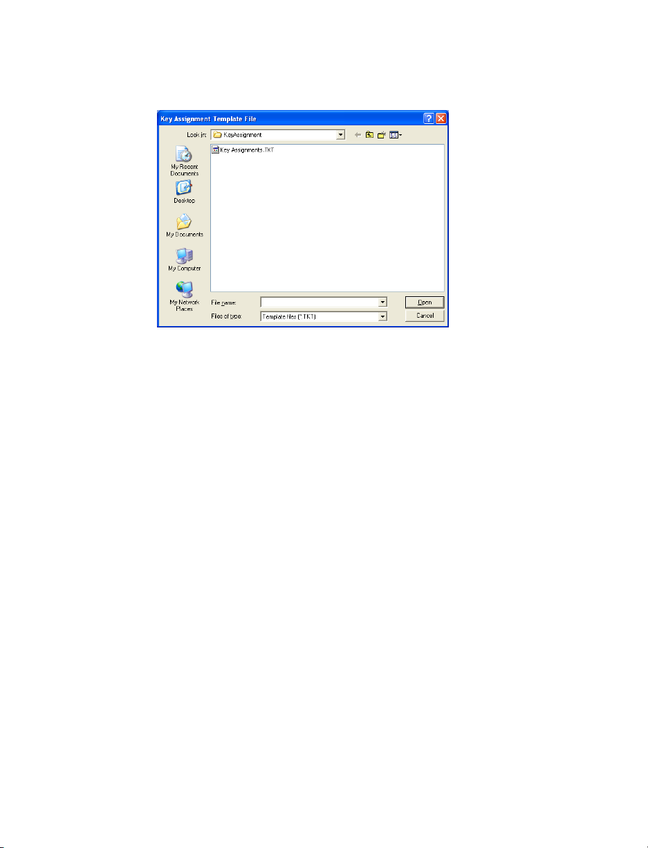
Using a template
1. To display the key assignments from a template file, click Use Template.
The Key Assignment Template File window appears.
2. Select the template file, and then click Open.
REMOTE EXTENSIONS
The System Information > Remote Extensions page allows you to set up
the name, phone number, line hunt group, and same line connect feature for
each remote extension.
A remote extension connects to an external phone number, but acts like a
local extension in your office. For example, a remote extension could connect
to an employee’s cell phone or home phone, or to a branch office.
There are ten remote extensions per TalkSwitch unit, which are numbered as
follows:
• TalkSwitch Unit 1 — 210 to 219
• TalkSwitch Unit 2 — 220 to 229
• TalkSwitch Unit 3 — 230 to 239
• TalkSwitch Unit 4 — 240 to 249
72 TALKS W I TCH CONFIGURATION
Page 93

Remote extensions are designed to operate with local major telephone
service providers. The feature may not function correctly with some
telephone and mobile operator’s networks, especially for international
phone numbers and mobile phones roaming internationally.
Setting up a remote extension
1. Expand System Information > Remote Extensions.
2. Select a remote extension tab.
3. Select the Activate Extension check box.
4. Enter the user’s Last name and First name. The names appear within the
configuration windows.
5. Enter the Remote phone number. Enter the number as you would
normally dial it (i.e. without the line hunt group number). You can enter
digits 0-9, space, dash, comma, and . A comma pauses dialing
for two seconds.
TALKSWITCH USER GUIDE 73
Page 94

6. Select the line hunt group in the Connect using list. The TalkSwitch unit
will use a line from this line hunt group to connect with the remote
extension. We recommend the default Hunt Group 9 unless you have set
up a different line hunt group for calling remote extensions.
7. If you have the 3-Way Calling/Conference service from the telephone
company, you can select the Use Same Line Connect check box. The same
line connect feature will direct the telephone company to put the caller
on hold, and will then use the same line to try the remote extension.
Because the same line is used, the line hunt group setting from Step 6 is
ignored.
If you do not select the Use Same Line Connect check box, the TalkSwitch
unit will put the caller on hold, and then use a second line to try the
remote extension. The second line will be from the line hunt group
selected in Step 6.
The same line connect feature is not compatible with some telephone
company lines.
If you enable the same line connect feature, the user will not be able to
transfer a call from the remote extension.
When the same line connect feature is in use, the caller hears silence
while they are on hold. This is because the caller is on hold at the
telephone company and not at the TalkSwitch unit. If you want the caller
to hear music on hold while their call is being forwarded to the remote
extension, do not use the same line connect feature.
8. Select the language for prompts heard by callers in the Prompts language
for this extension list.
Remote extensions and telephone company services
See Appendix B: TalkSwitch and Telephone Company Calling Services on page
231 for information about using the Transfer and Clear, Prompted Ring Back,
and Ringback Tones services with remote extensions.
EXTENSION RING GROUPS
The System Information > Extension Ring Groups page allows you to set
up the name, local extensions, and ring pattern for each ring group.
A ring group is a group of local extensions that ring in unison. Local
extensions and auto attendants can dial a ring group.
74 TALKS W I TCH CONFIGURATION
Page 95

There are ten ring groups in the TalkSwitch system, which are numbered 300
to 309. By default, 300 is configured to ring all local extensions.
Ring groups have two main uses:
• A ring group can reach a group of employees. For example, ring group
301 can ring the sales group at extensions 111, 112, 113, and 114. When
a customer calls the sales group, the first available salesperson answers
for the group.
• A ring group with a different ring pattern can differentiate callers. For
example, the president doesn’t want to answer calls from the general
public, but wants to be alerted when important colleagues are on the
line. His local extension is 111, but you can configure ring group 305 to
ring his phone with a different ring pattern. The president tells his
colleagues to reach him at extension 305, which is his private extension.
He can tell by the ring pattern if the caller dialed extension 111 or 305,
and can react accordingly.
1. Expand System Information > Extension Ring Groups.
2. Select the ring group tab.
3. Select the Activate Ring Group check box.
4. Enter the Ring Group name. The name appears within the configuration
windows.
TALKSWITCH USER GUIDE 75
Page 96

5. In the Set Ring Group area, select the local extensions that you want to
ring in unison.
6. Select a Ring pattern to indicate the call is for the ring group.
7. Select the Include Ring Group number check box to display the ring group
number with the Caller ID information.
ON-HOLD/RINGBACK
The System Information > On-Hold/Ringback page allows you to set up
music on hold. Music on hold is a double beep tone by default, or you can set
up music or a recorded message. It plays while the caller is on hold, or is
being transferred to an extension.
You can add music on hold to your system from an external audio source, or
from an internal .wav file. See Setting up music on hold on page 21.
If you connect an external audio source to the music jack but select Play
‘double beep’ tones, Double beep tones, or Ringback, the caller will hear
both the external audio source and the beep sounds.
The recording time for internal music on hold, voicemail, and the auto
attendants is two hours per TalkSwitch unit. You can expand the built-in
memory using memory cards.
1. Expand System Information > On-Hold/Ringback.
2. In the On-Hold Settings area, select the sound to play while the caller is
on hold. Choices are:
• Play ‘double beep’ tones
76 TALKS W I TCH CONFIGURATION
Page 97

• Play music whose source is connected to the MUSIC jack
• Play music from file loaded on TalkSwitch
3. If you selected Play music from file loaded on TalkSwitch:
a) Create an 8 kHz, 8 bit, Mono, u-Law .wav file that contains the music
or recorded message.
You can convert .mp3 and other file formats to .wav with a utility
like Audio Converter and Ripper from www.audioi.com.
b) Click Load wav file. The following window appears.
c) Click Yes. The Load Audio File window appears.
d) Select an 8 kHz, 8 bit, Mono, u-Law .wav file, and then click Open.
4. Adjust the volume of music on hold.
a) Check the volume by placing a test call and going on hold.
b) Change the volume by setting the Playback volume for music file list.
Choices are:
•Loudest
• Louder
•Default
•Quieter
•Quietest
c) Choose File > Save settings to TalkSwitch. Alternatively, you can
click the Save settings to TalkSwitch icon.
You must save the configuration for the volume setting to take
effect.
d) Repeat Steps a to c.
TALKSWITCH USER GUIDE 77
Page 98

5. In the Transfer Settings area, select the sound to play while the caller is
being transferred. Choices are:
• Double beep tones
•Music
• Ringback
VOICEMAIL
Voicemail contains the following items:
• Local Ext. Voicemail
• Remote Ext. Voicemail
• General Voicemail
• Global Settings
Voicemail can be activated with a mailbox, as an announcement only, or
deactivated. There are three types of voicemail:
• Local extension voicemail is associated with a local extension. By
default, each local extension mailbox is activated.
• Remote extension voicemail is associated with a remote extension. By
default, each remote extension has voicemail deactivated.
• General voicemail is not associated with any extension, but is for general
use or for a group. By default, general voicemail is deactivated.
The procedures for setting up voicemail are the same for each type. See
Setting up voicemail on page 78 and Global Settings on page 87.
The recording time for internal music on hold, voicemail, and the auto
attendants is two hours per TalkSwitch unit. You can expand the built-in
memory using memory cards.
SETTING UP VOICEMAIL
The Voicemail pages allow you to activate a mailbox or announcement, enter
the voicemail name, select the action to perform if the caller dials 0, load the
greeting, and set up voicemail notification.
1. Display the Voicemail page:
78 TALKS W I TCH CONFIGURATION
Page 99

• To configure a local extension mailbox, expand Voicemail > Local
Ext. Voicemail.
• To configure a remote extension mailbox, expand Voicemail >
Remote Ext. Voicemail.
• To configure a general mailbox, expand Voicemail > General
Voicemail.
The following screen capture shows the Local Ext. Voicemail page, but
the Remote Ext. Voicemail and General Voicemail pages are identical.
2. Select a local extension, remote extension or general tab.
3. Activate the mailbox or announcement. Choices are:
• Activated as mailbox activates the greeting and the mailbox, and
enables all the controls on the page. The caller will hear a greeting,
and will be able to leave a message in the mailbox.
• Activate as announcement activates the greeting, deactivates the
mailbox, and disables the Voicemail Notification Settings area. The
caller will hear a greeting, but will not be able to leave a message.
• Deactivated deactivates the greeting and the mailbox, and disables all
the controls on the page.
TALKSWITCH USER GUIDE 79
Page 100

4. If required, enter the voicemail Name. By default, the name is from the
First Name and Last Name boxes of the System Information > Local
Extensions or System Information > Remote Extensions page. A
general voicemail has no default name.
5. In the Mailbox Options area, select the action to perform if a caller dials
0. You can select one action for mode 1, and another action for mode 2.
Choices are:
• go to voice mailbox
•go to local ext.
•go to remote ext.
• go to ring group
•play announcement
• go to auto attendant
•perform no action
6. Depending on the action selected in Step 5, enter the extension number
or auto attendant.
7. Load the greeting into the TalkSwitch unit.
a) Create an 8 kHz, 8 bit, Mono, u-Law .wav file that contains the
greeting.
The greeting should tell the caller to dial 0 to perform the action
selected in Step 5 and 6.
b) Click Load Greeting. The following window appears.
c) Click Yes. The Load Voicemail Greeting window appears.
d) Select an 8 kHz, 8 bit, Mono, u-Law .wav file, and then click Open.
80 TALKS W I TCH CONFIGURATION
 Loading...