

Page 1

ANSWERS WITH INTELLIGENCE
®
TALKSWITCH DOCUMENTATION
USER GUIDE
RELEASE 3.24
CT.TS005.001101.UK
For use in
United Kingdom and Ireland
Page 2

Copyright Information
TalkSwitch Copyright 2006 — All Rights Reserved.
TalkSwitch is a division of Centrepoint Technologies Inc.
TalkSwitch and Appello® are registered trademarks of Centrepoint
Technologies Inc.
Reproduction, adaptation or translation without prior written permission
is prohibited, except as allowed under the copyright laws.
Information in this user guide is subject to change without notice and
does not represent any commitment on the part of TalkSwitch. No part of
this user guide may be reproduced or transmitted in any form or by any
means, electronic or mechanical, including photocopying, recording, or
information storage and retrieval systems, or translated to another
language, for any purpose other than the licensee’s personal use and, as
specifically allowed in the licensing agreement, without the express
written permission of TalkSwitch.
First Edition, April 2006
CT.TS005.001101.UK
Page 3

TALKSWITCH USER GUIDE • UK & IRELAND
Thank you for purchasing the TalkSwitch Phone System. This user guide
provides instructions for installing, configuring and using your TalkSwitch.
Please read this section before you start installing the product.
Important Safety Information
Power & Lightning Surges
Surge protection devices are recommended in areas where lightning or power
surges are likely to occur. Avoid using corded telephones during a lightning
storm. There may be a risk of electric shock. Do not install a TalkSwitch
system during an electrical storm.
If your TalkSwitch was supplied with
telephone line lightning surge protectors to met local regulatory
requirements, please install the devices in accordance with the instructions
provided.
Power Adaptor & Power Cords
Use the power adaptor and power cords provided with the TalkSwitch. Other
power adaptors may damage the unit. Check that the power adaptor voltage
rating matches the local supply. If they do not match, please contact your
TalkSwitch reseller for advice.
Temperature & Environment
Operate TalkSwitch in a location where the temperature is between 0°C and
40°C.
• Do not expose it to a heat source or direct sunlight and avoid damp,
dusty locations.
• Do not expose it to vibration, hazardous chemicals or explosives.
• Do not locate the TalkSwitch unit where it is subjected to electrical noise
generating devices such as motors, fluorescent lamps or radio
transmitting devices.
• Do not stack TalkSwitch units directly on top of each other.
PREFACE
Page 4

PREFACE
• Allow the TalkSwitch to reach room temperature before installation after
shipping or storage to avoid problems caused by condensation.
Maintenance
Do not attempt to repair a TalkSwitch unit yourself.
Advisory Information
Power Failure
When a power failure occurs, Line 1 connects to Extension 4 on each unit to
enable incoming and outgoing calls over PSTN telephone lines. Consider
using an Uninterrupted Power Supply (UPS) and surge protection for
applications requiring uninterrupted operation or in areas that are subject to
frequent power outages.
Emergency Service Access
Ensure that you do not block extension access to Emergency Services when
you set up the Automatic Route Section and Toll Restriction features.
PBX Fraud and Misuse
We recommend that you use password security for the administrator. Change
the password frequently to prevent unauthorized users from making calls
through your PBX.
TalkSwitch Usage
The model of TalkSwitch you have purchased is designed and supplied to
meet the technical standards for use in specific countries and for connection
to the major telephone service providers in those countries. It is subject to
regulatory certification and compliances as detailed in the appendices.
Export and use outside the intended countries is not recommended or
supported by TalkSwitch.
Call Redirection & Service Provider Billing Advisory
Use of the Automatic Route Selection, Toll Restriction and Call Detail
Recording features does not imply any guarantee whatsoever by regulatory
authorities, your telephone service provider(s), TalkSwitch or its distributors
and resellers, with regard to the accuracy of these features and that the use
of such a features may not be considered by a telephone company in any
disputes which may arise regarding the accuracy of any subscriber's
telephone account.
Waste Disposal
Please dispose of the product in compliance with local regulations for
electrical and electronic waste material.
Page 5

TABLE OF CONTENTS I
TABLE OF CONTENTS
CHAPTER 1: TALKSWITCH INSTALLATION
1.1 Installation . . . . . . . . . . . . . . . . . . . . . . . . . . . . . . . . . . . . . . . . . . . . . . . . . . . . . 1
1.2 Front Panel lights . . . . . . . . . . . . . . . . . . . . . . . . . . . . . . . . . . . . . . . . . . . . . . . . 2
1.3 Back Panel . . . . . . . . . . . . . . . . . . . . . . . . . . . . . . . . . . . . . . . . . . . . . . . . . . . . . . 3
1.3.1 TalkSwitch 24 Models . . . . . . . . . . . . . . . . . . . . . . . . . . . . . . . . . . . . . . . 3
1.3.2 TalkSwitch 48 Models . . . . . . . . . . . . . . . . . . . . . . . . . . . . . . . . . . . . . . . 3
1.4 Plugging into the Back Panel . . . . . . . . . . . . . . . . . . . . . . . . . . . . . . . . . . . . . . . 5
1.4.1 Connecting telephone lines . . . . . . . . . . . . . . . . . . . . . . . . . . . . . . . . . . 5
1.4.2 Connecting extension telephones and other devices . . . . . . . . . . . . . 6
1.4.3 Connecting devices to the Music and PA ports . . . . . . . . . . . . . . . . . . . 6
1.4.4 Connecting TalkSwitch to a LAN and/or PC . . . . . . . . . . . . . . . . . . . . . . 7
1.4.4.1 Connecting TalkSwitch to a LAN for local configuration . . . . . 7
1.4.4.2 Connecting TalkSwitch to a PC using a USB cable . . . . . . . . . . 7
1.4.4.3 Connecting TalkSwitch to a PC using a Serial cable . . . . . . . . 7
1.4.4.4 Connecting to TalkSwitch over IP . . . . . . . . . . . . . . . . . . . . . . . 8
1.5 Using 2 or more TalkSwitch units on a LAN . . . . . . . . . . . . . . . . . . . . . . . . . . . . 8
1.5.1 Connecting 2 or more TalkSwitch units to a LAN . . . . . . . . . . . . . . . . . . 8
1.5.2 Setting the Unit ID for the first time . . . . . . . . . . . . . . . . . . . . . . . . . . . . 9
1.5.3 Changing the Unit ID . . . . . . . . . . . . . . . . . . . . . . . . . . . . . . . . . . . . . . . 10
1.5.4 How unit IDs affect system extension numbers . . . . . . . . . . . . . . . . . . 10
1.5.5 Keep track of the lines and extensions . . . . . . . . . . . . . . . . . . . . . . . . 11
1.5.6 Optimizing the system for networked use . . . . . . . . . . . . . . . . . . . . . . 11
Page 6

II TABLE OF CONTENTS
CHAPTER 2: TALKSWITCH CONFIGURATION
2.1 Install the TalkSwitch Configuration Software . . . . . . . . . . . . . . . . . . . . . . . . . 13
2.2 Running the TalkSwitch software . . . . . . . . . . . . . . . . . . . . . . . . . . . . . . . . . . . 14
2.3 System Configuration . . . . . . . . . . . . . . . . . . . . . . . . . . . . . . . . . . . . . . . . . . . . 15
2.3.1 The configuration screen . . . . . . . . . . . . . . . . . . . . . . . . . . . . . . . . . . . . 15
2.3.1.1 File Menu . . . . . . . . . . . . . . . . . . . . . . . . . . . . . . . . . . . . . . . . 16
2.3.1.2 View Menu . . . . . . . . . . . . . . . . . . . . . . . . . . . . . . . . . . . . . . . 16
2.3.1.3 Tools Menu . . . . . . . . . . . . . . . . . . . . . . . . . . . . . . . . . . . . . . . 16
2.3.1.4 Help Menu . . . . . . . . . . . . . . . . . . . . . . . . . . . . . . . . . . . . . . . 17
2.3.2 Configuration Navigation . . . . . . . . . . . . . . . . . . . . . . . . . . . . . . . . . . . . 17
2.3.2.1 Configuration considerations connecting
multiple units to a LAN . . . . . . . . . . . . . . . . . . . . . . . . . . . . . 18
2.3.3 System Information . . . . . . . . . . . . . . . . . . . . . . . . . . . . . . . . . . . . . . . . 18
2.3.3.1 Administration . . . . . . . . . . . . . . . . . . . . . . . . . . . . . . . . . . . . 19
2.3.3.2 IP Configuration . . . . . . . . . . . . . . . . . . . . . . . . . . . . . . . . . . . 20
2.3.3.3 VoIP Configuration . . . . . . . . . . . . . . . . . . . . . . . . . . . . . . . . . 23
2.3.3.4 PSTN analogue telephone lines . . . . . . . . . . . . . . . . . . . . . . 28
2.3.3.5 VoIP Numbers . . . . . . . . . . . . . . . . . . . . . . . . . . . . . . . . . . . . . 31
2.3.3.6 Line Hunt Groups . . . . . . . . . . . . . . . . . . . . . . . . . . . . . . . . . . 32
2.3.3.7 Automatic Route Selection and Toll Restriction . . . . . . . . . . 33
2.3.3.8 Fax Information . . . . . . . . . . . . . . . . . . . . . . . . . . . . . . . . . . . 39
2.3.3.9 Local Extensions . . . . . . . . . . . . . . . . . . . . . . . . . . . . . . . . . . 40
2.3.3.10 Remote Extensions . . . . . . . . . . . . . . . . . . . . . . . . . . . . . . . . 42
2.3.3.11 Extension Ring Groups . . . . . . . . . . . . . . . . . . . . . . . . . . . . . . 44
2.3.3.12 On-hold/Ringback . . . . . . . . . . . . . . . . . . . . . . . . . . . . . . . . . 46
2.3.4 Voicemail. . . . . . . . . . . . . . . . . . . . . . . . . . . . . . . . . . . . . . . . . . . . . . . . . 47
2.3.4.1 Local Extension Voicemail . . . . . . . . . . . . . . . . . . . . . . . . . . . 47
2.3.4.2 Remote Extension Voicemail . . . . . . . . . . . . . . . . . . . . . . . . . 50
2.3.4.3 General Voicemail . . . . . . . . . . . . . . . . . . . . . . . . . . . . . . . . . 51
2.3.4.4 Global Settings . . . . . . . . . . . . . . . . . . . . . . . . . . . . . . . . . . . . 52
2.3.5 Call Handling . . . . . . . . . . . . . . . . . . . . . . . . . . . . . . . . . . . . . . . . . . . . . 53
2.3.5.1 Modes . . . . . . . . . . . . . . . . . . . . . . . . . . . . . . . . . . . . . . . . . . . 53
2.3.5.2 Auto Attendant . . . . . . . . . . . . . . . . . . . . . . . . . . . . . . . . . . . . 54
2.3.5.3 PSTN analogue telephone Lines . . . . . . . . . . . . . . . . . . . . . . 60
2.3.5.4 VoIP Numbers . . . . . . . . . . . . . . . . . . . . . . . . . . . . . . . . . . . . . 62
2.3.5.5 Local Extensions — Call Cascade . . . . . . . . . . . . . . . . . . . . . 63
2.3.5.6 Remote Extensions — Call Cascade . . . . . . . . . . . . . . . . . . . 66
2.3.5.7 Extension Ring Groups — Call Cascade . . . . . . . . . . . . . . . . 68
Page 7

TABLE OF CONTENTS III
2.3.6 Call Back/DISA . . . . . . . . . . . . . . . . . . . . . . . . . . . . . . . . . . . . . . . . . . . . 69
2.3.6.1 Auto Call Back . . . . . . . . . . . . . . . . . . . . . . . . . . . . . . . . . . . . 71
2.3.6.2 Prompted Call Back . . . . . . . . . . . . . . . . . . . . . . . . . . . . . . . . 73
2.3.6.3 DISA . . . . . . . . . . . . . . . . . . . . . . . . . . . . . . . . . . . . . . . . . . . . 75
2.3.7 Options . . . . . . . . . . . . . . . . . . . . . . . . . . . . . . . . . . . . . . . . . . . . . . . . . .76
2.3.7.1 Audio Controls . . . . . . . . . . . . . . . . . . . . . . . . . . . . . . . . . . . . 76
2.3.7.2 Transfer Options . . . . . . . . . . . . . . . . . . . . . . . . . . . . . . . . . . . 78
2.3.7.3 Miscellaneous . . . . . . . . . . . . . . . . . . . . . . . . . . . . . . . . . . . .79
2.3.7.4 Troubleshooting . . . . . . . . . . . . . . . . . . . . . . . . . . . . . . . . . . . 82
2.3.7.5 Troubleshooting — Advanced . . . . . . . . . . . . . . . . . . . . . . . . 84
CHAPTER 3: USING TALKSWITCH
3.1 In the Office — Receiving Calls with or without the Auto Attendant . . . . . . . . 87
3.1.1 Receiving calls using the Auto Attendant . . . . . . . . . . . . . . . . . . . . . . . 87
3.1.2 Receiving calls without the Auto Attendant . . . . . . . . . . . . . . . . . . . . . 87
3.2 In the Office — Making and Receiving Calls . . . . . . . . . . . . . . . . . . . . . . . . . . . 88
3.2.1 Making calls from a Local Extension . . . . . . . . . . . . . . . . . . . . . . . . . . . 88
3.2.2 Receiving calls at a Local Extension . . . . . . . . . . . . . . . . . . . . . . . . . . . 88
3.2.3 Placing calls on Hold at a Local Extension . . . . . . . . . . . . . . . . . . . . . . 89
3.2.4 Transferring calls . . . . . . . . . . . . . . . . . . . . . . . . . . . . . . . . . . . . . . . . . .89
3.2.5 Call Park — Parking and retrieving callers . . . . . . . . . . . . . . . . . . . . . . 90
3.2.5.1 Parking a caller . . . . . . . . . . . . . . . . . . . . . . . . . . . . . . . . . . . . 90
3.2.5.2 Parking a caller using Auto Park . . . . . . . . . . . . . . . . . . . . . . 91
3.2.5.3 Retrieving a parked call . . . . . . . . . . . . . . . . . . . . . . . . . . . . . 91
3.2.5.4 Using Call Park with the Paging option . . . . . . . . . . . . . . . . . 91
3.2.6 Call Queue/UCD/Call Waiting — Queuing and retrieving callers . . . . . 91
3.2.6.1 Queuing calls to a single extension . . . . . . . . . . . . . . . . . . . . 91
3.2.6.2 Queuing callers to an Extension Ring Group . . . . . . . . . . . . .92
3.2.7 Using the TalkSwitch Call Waiting feature . . . . . . . . . . . . . . . . . . . . . . 93
3.2.8 Conference calling with TalkSwitch . . . . . . . . . . . . . . . . . . . . . . . . . . . . 93
3.2.9 Making and receiving calls using VoIP . . . . . . . . . . . . . . . . . . . . . . . . . 94
3.2.10 Using Phones connected in parallel to TalkSwitch . . . . . . . . . . . . . . . 95
3.2.11 Modems and telephone line access . . . . . . . . . . . . . . . . . . . . . . . . . . . 96
3.3 Out of the Office — Receiving Calls through Call Forwarding . . . . . . . . . . . . . . 97
3.3.1 The three ways to forward calls . . . . . . . . . . . . . . . . . . . . . . . . . . . . . . . 97
3.3.2 Transferring calls from a Remote Extension . . . . . . . . . . . . . . . . . . . . . 97
3.3.3 Screening options for forwarded calls . . . . . . . . . . . . . . . . . . . . . . . . . . 98
3.3.4 Calls over VoIP with SIP phones and Gateways . . . . . . . . . . . . . . . . . .99
Page 8

IV TABLE OF CONTENTS
3.4 Using the TalkSwitch Voicemail System . . . . . . . . . . . . . . . . . . . . . . . . . . . . . . 99
3.4.1 Activating voicemail boxes . . . . . . . . . . . . . . . . . . . . . . . . . . . . . . . . .100
3.4.2 Retrieving messages/Accessing a voice mailbox . . . . . . . . . . . . . . . . 100
3.4.3 Pager and Cell Phone notification . . . . . . . . . . . . . . . . . . . . . . . . . . . .102
3.5 Music on Hold . . . . . . . . . . . . . . . . . . . . . . . . . . . . . . . . . . . . . . . . . . . . . . . . . 103
3.6 Mode Switching Options . . . . . . . . . . . . . . . . . . . . . . . . . . . . . . . . . . . . . . . . . 103
3.7 Out of the Office — Making Calls with Call Back and DISA (Call Bridge) . . . . 104
3.7.1 Using DISA (Call Bridge) . . . . . . . . . . . . . . . . . . . . . . . . . . . . . . . . . . . . 104
3.7.2 Using Call Back . . . . . . . . . . . . . . . . . . . . . . . . . . . . . . . . . . . . . . . . . . 105
3.8 Upgrading the TalkSwitch Software and Firmware . . . . . . . . . . . . . . . . . . . . 107
CHAPTER 4: CALL DETAIL RECORD (CDR) LOGGING
4.1 Enabling Call Detail Record (CDR) logging . . . . . . . . . . . . . . . . . . . . . . . . . . . 111
4.2 Retrieving Data . . . . . . . . . . . . . . . . . . . . . . . . . . . . . . . . . . . . . . . . . . . . . . . . .112
4.2.1 Web Interface — Store to File on TalkSwitch . . . . . . . . . . . . . . . . . . . 112
4.2.2 Serial Interface — Real Time to Serial Interface . . . . . . . . . . . . . . . . . 114
4.3 Analyzing the Data . . . . . . . . . . . . . . . . . . . . . . . . . . . . . . . . . . . . . . . . . . . . . .115
CHAPTER 5: VOIP INFORMATION
5.1 Introduction to VoIP . . . . . . . . . . . . . . . . . . . . . . . . . . . . . . . . . . . . . . . . . . . . . 119
5.2 Optimizing Your IP Network for VoIP . . . . . . . . . . . . . . . . . . . . . . . . . . . . . . . . 119
5.2.1 The Broadband Connection . . . . . . . . . . . . . . . . . . . . . . . . . . . . . . . . .119
5.2.2 The Router/NAT/Firewall . . . . . . . . . . . . . . . . . . . . . . . . . . . . . . . . . . . 120
5.2.3 The Local Area Network . . . . . . . . . . . . . . . . . . . . . . . . . . . . . . . . . . . . 121
5.3 FAQ . . . . . . . . . . . . . . . . . . . . . . . . . . . . . . . . . . . . . . . . . . . . . . . . . . . . . . . . . .121
APPENDICES
A: Help and Troubleshooting . . . . . . . . . . . . . . . . . . . . . . . . . . . . . . . . . . . . . . . . . . 127
B: Using TalkSwitch with Telephone Company Calling Services . . . . . . . . . . . . . . 137
C: Quick Commands and Touch-Tone Functions . . . . . . . . . . . . . . . . . . . . . . . . . . . 141
D: Regulatory Information . . . . . . . . . . . . . . . . . . . . . . . . . . . . . . . . . . . . . . . . . . . . 147
E: TalkSwitch One-Year Warranty . . . . . . . . . . . . . . . . . . . . . . . . . . . . . . . . . . . . . . . 149
F: Specifications . . . . . . . . . . . . . . . . . . . . . . . . . . . . . . . . . . . . . . . . . . . . . . . . . . . .151
G: TalkSwitch and Power Interruptions . . . . . . . . . . . . . . . . . . . . . . . . . . . . . . . . . . 153
H: Copyright and Licensing Notices . . . . . . . . . . . . . . . . . . . . . . . . . . . . . . . . . . . . . 155
Glossary . . . . . . . . . . . . . . . . . . . . . . . . . . . . . . . . . . . . . . . . . . . . . . . . . . . . . . . . . . . 159
Page 9

TALKSWITCH INSTALLATION 1
1.1 INSTALLATION
If any of these items are missing, please contact your TalkSwitch dealer.
Open the system package, which will contain:
• The TalkSwitch Unit
• AC Power Adaptor
110V socket mount adaptor or 230V with power cord
(subject to market model)
• USB cable (supplied only with models
without a LAN port)
• RJ-45 LAN cable (supplied with all models
with a LAN port)
• Telephone cables (one per telephone line
port)
• CD containing configuration program
installation wizard and user documentation
• Extension Reference Cards
• TalkSwitch Start Guide
• Warranty Card
Note: The VoIP symbol indicates sections that only apply to
VoIP enabled TalkSwitch units. We recommend that
VoIP users read Chapter 5: VoIP Information.
CHAPTER 1
TALKSWITCH INSTALLATION
Page 10

2TALKSWITCH USER GUIDE • UK & IRELAND
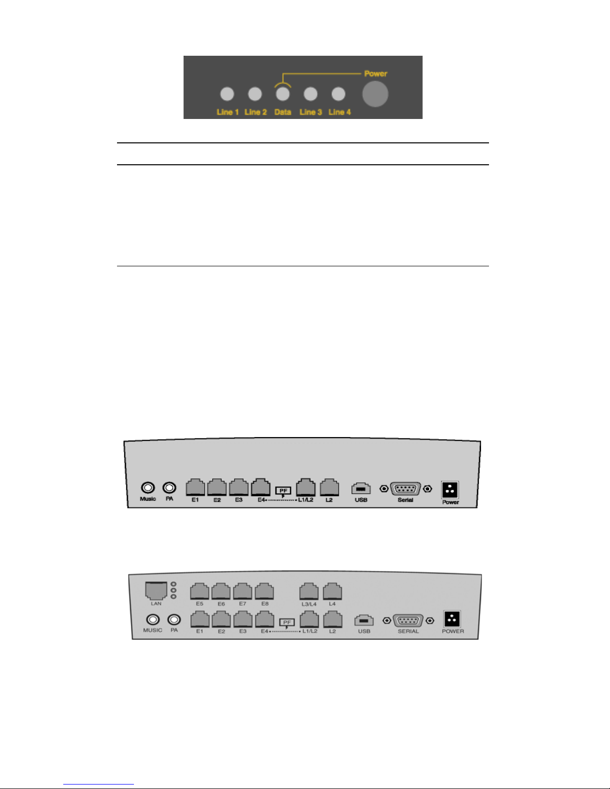
1.2 FRONT PANEL LIGHTS
The front panel consists of a power button (“Power”) and five LED (Light
Emitting Diode) lights indicating the usage of the lines with different states
of illumination.
Light: State Description
Line 1 On Solid Line 1 is currently in use.
Pulsing Slowly Line 1 caller is on hold.
Flickering Line 1 is ringing.
Quick Pulse Line 1 is engaged by a device that is sharing
the line with TalkSwitch.
Line 2 On Solid Line 2 is currently in use.
Pulsing Slowly Line 2 caller is on hold.
Flickering Line 2 is ringing.
Quick Pulse Line 2 is engaged by a device that is sharing
the line with TalkSwitch.
Power/Data On Solid TalkSwitch is powered on.
Flickering The PC connected (via Serial or USB) to
TalkSwitch is either sending or retrieving
information from TalkSwitch.
Pulsing Slowly Global Message Waiting Indicator (optional).
Note: Lights for line 3 and line 4 apply to Talkswitch 48 models. For more
details on line LED light error codes, see Appendix A:
Help and Troubleshooting.
Line 3 On Solid Line 3 is currently in use.
Pulsing Slowly Line 3 caller is on hold.
Flickering Line 3 is ringing.
Quick Pulse Line 3 is engaged by a device that is sharing
the line with TalkSwitch.
Page 11
TALKSWITCH INSTALLATION 3
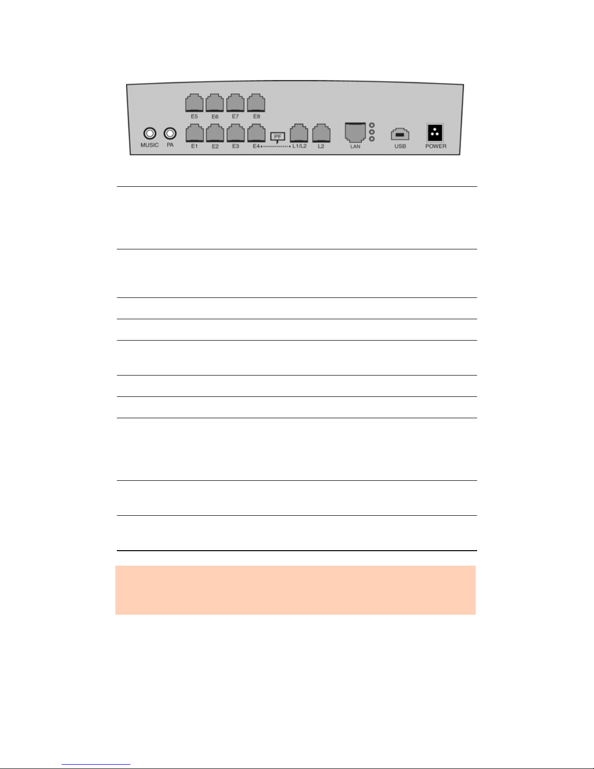
1.3 BACK PANEL
Before you connect all your phones and lines to TalkSwitch, you may want to
configure the unit. This minimizes the disruption time of your telephone
lines during the system setup. See Chapter 2: Configuration.
1.3.1 TalkSwitch 24 Models
1.3.2 TalkSwitch 48 Models
Line 4 On Solid Line 4 is currently in use.
Pulsing Slowly Line 4 caller is on hold.
Flickering Line 4 is ringing.
Quick Pulse Line 4 is engaged by a device that is sharing
the line with TalkSwitch.
TalkSwitch configurations are subject to market availability.
Light: State Description
Page 12
4TALKSWITCH USER GUIDE • UK & IRELAND
Ports Purpose
L1-L2 and
L3-L4
(subject to model)
Telephone cables for connection to telephone company
analogue (PSTN) telephone line ports or demarcation
point; or telephone line lightening protection if required
(see notes 1 & 2)
E1-E4 and
E5-E8
(subject to model)
Local extension telephone sets, fax machines or data
modems
USB USB cable to PC for system configuration
SERIAL
(subject to model)
Serial cable to PC for system configuration
Music 1/8” socket for external Music on Hold input
PA 1/8” socket for output to Public Address system
LAN
(subject to model)
RJ-45 10BaseT Ethernet for connection to LAN; used for
connection to other co-located TalkSwitch units, VoIP
networking and configuraion from local PC or remotely
over Internet
POWER Plug in supplied AC Power Adapter; (Rating 16VAC 1.5 A)
ONLY use the power adaptor supplied with the system
Memory Slot
(on side of system)
For Voicemail (incl. Auto Attendant, MoH) Expansion.
Works only with TalkSwitch Voicemail Expansion cards
Note: The ‘PF’ box in between E4 and L1/L2 represents power failure
support. In the event of a power failure or loss of power to TalkSwitch,
Extension 114 is able to receive and make calls on Line 1.
1.3.3 TalkSwitch 28 Models
Page 13

TALKSWITCH INSTALLATION 5
1.4 PLUGGING INTO THE BACK PANEL
1.4.1 Connecting telephone lines
You can connect the TalkSwitch to the telephone company’s line sockets
using the 2-wire telephone cables provided to ports L1-L2 or L1-L4 (subject
to model). Take note of which telephone line is connected to each Line port
— this information will be used in the configuration section.
In cases where a telephone company’s ISDN BRA service is installed using an
NTE with two analogue line “ab” ports, the TalkSwitch telephone lines can be
connected to the NTE’s ab ports (Please check with your local telephone
company).
The use of 4-wire telephone cables to combine L1/L2 or L3/L4 wiring requires
a special installation procedure and may not be compatible with some standard
telephone sockets. It is not recommended for general use.
If your TalkSwitch was supplied with telephone lightning protectors to comply
with local regulatory requirements, they must be installed on each telephone
line as detailed in the instructions provided with the lightning protectors.
In cases where the telephone company lines are terminated on a
Connection Box with IDC or screw terminals, it is recommended that “RJ11 Wiring-Tails” are used. These are single or multi-pair cables with
0.5mm solid core wire one end terminated in an RJ-11 connector(s).
These RJ-11 wiring tails may be available where you purchased your
system or provided by your installer.
Advisory: In order to minimize disruption to your business, you may
want to configure TalkSwitch before connecting it to your telephone lines
and extension phones.
Warning: The TalkSwitch line ports are sensitive to high-voltage spikes
from lightning. If you live in an area where electrical storms occur
regularly, we recommend that you protect TalkSwitch by plugging the
telephone cords coming from the TalkSwitch line ports to a surge
protection device connected to the incoming telephone lines.
Page 14

6TALKSWITCH USER GUIDE • UK & IRELAND
1.4.2 Connecting extension telephones and other devices
You can connect any regular analogue extension telephone set, cordless (e.g.
DECT) telephone, or fax machine to the extension ports – E1-E4 and E1-E8
(subject to model).
Attach a single-line corded or cordless telephone, fax machine or
answering machine
Connect your single-line analog telephone or fax machine to one of the
TalkSwitch extension ports E1-E4 (all TalkSwitch models);
E5-E8 (TalkSwitch 48 models only)) just as you would be plugging them into a
standard telephone wall port.
Attach an Internal or External Modem
Plug the modem’s telephone cable into a TalkSwitch extension port. Your
modem is now a TalkSwitch extension that can access all lines and take
advantage of TalkSwitch’s call routing features.
If you don’t want to change your dial-up settings for the modem, enable
Direct Line Access for the extension associated to the modem. See section
2.3.3.9 (Local Extensions -> Direct Line Access) for more details on
configuring Direct Line Access.
1.4.3 Connecting devices to the Music and PA ports
The Music port is designed to support any audio source (CD player, radio, tape
player, sound card etc.) for playing music or messages to callers while on
hold. Connect the audio source via its headphone output to the Music port.
The Music port requires a 1/8" (3.5mm) mono phono connector. If you have a
48 model with more than one TalkSwitch connected to a LAN, you need to
provide audio to the Music ports on each TalkSwitch.
The PA port can be connected to a PA System for external paging or to an
amplification system to screen voicemail or to use as a line simulator. The PA
port requires a 1/8" (3.5mm) mono phono connector. If you have a 48 model
with more than one TalkSwitch connected to a LAN, you need to provide a
connection from each TalkSwitch to the PA system.
In cases where extensions will be wired through in-building wiring and a
Connection Box with IDC or screw terminals, it is recommended that “RJ-11
Wiring-Tails” are used. These are single or multi-pair cables with 0.5mm solid
core wire one end terminated in an RJ-11 connector(s). These may be
available from your TalkSwitch Reseller or provided by your installer.
To connect telephones with BT style plugs it is recommended that extensions
are wired through a Master Socket or an in-line adaptors with a capacitor.
This also ensures compatibility with some telephones that require 3-wire
connections for the telephone to ring.
Page 15

TALKSWITCH INSTALLATION 7
1.4.4 Connecting TalkSwitch to a LAN and/or PC
There are currently four ways to connect to TalkSwitch for PC configuration
— over the LAN (Ethernet port), USB, Serial, or Internet.
1.4.4.1 Connecting TalkSwitch to a LAN for local configuration
If you want to connect multiple TalkSwitch units to a LAN, see section 1.5.
To connect TalkSwitch to a LAN for configuration purposes,
use the supplied Ethernet cable (Category 5 cable with RJ45
connectors on either end, provided with 48 models). Connect
TalkSwitch to the switch or hub. The top LED lights up to
indicate a connection is established.
1.4.4.2 Connecting TalkSwitch to a PC using a USB cable
If you have an available USB port and a USB cable, connect TalkSwitch to the
PC using the USB cable (provided with 24 models).
Make sure no other communications programs* are running the same time
you are using the TalkSwitch configuration software.* They may include
Palm Pilot, Hot Sync, TalkWorks or digital camera software. These programs
tend to occupy COM ports thus making them unavailable for other programs.
1.4.4.3 Connecting TalkSwitch to a PC using a Serial cable
If you wish to use an available Serial port, connect TalkSwitch to your PC
with a RS-232 Serial cable (not included). By default, TalkSwitch is shipped
with the Serial and LAN ports enabled and the USB port disabled.
When you run the TalkSwitch software, select ‘Serial’ as the connection type
then select the Serial Port associated to this physical Serial port on your PC.
Make sure you do not have any other communications programs running at
the same time you want to use the TalkSwitch configuration software. These
may include Palm Pilot, Hot Sync, TalkWorks, digital camera software. These
LAN: Use the provided Ethernet cable to connect TalkSwitch to the LAN
via your switch (TalkSwitch models with LAN ports only).
USB: Use a USB cable to connect TalkSwitch to an available USB port
on your PC or on the USB hub.
Serial: Use a serial cable (RS232) to connect TalkSwitch to an available
Serial COM port on your PC.
Internet: The TalkSwitch models with LAN ports support remote
configuration from a PC via IP from a local or remote location.
Page 16

8TALKSWITCH USER GUIDE • UK & IRELAND
programs tend to ‘hold’ onto COM ports, making them unavailable for any other
programs.
If you are having problems communicating with TalkSwitch, please check the
Chapter 6: Help and Troubleshooting.
1.4.4.4 Connecting to TalkSwitch over IP
Ensure TalkSwitch is connected to a LAN with the supplied Category 5 cable.
The top LED should light up to indicate a connection has been established with
a switch or hub. To support remote configuration over IP, map port 9393 from
your firewall to TalkSwitch. Please refer to the manual for your router/firewall
to activate port forwarding.
When you open the TalkSwitch software, you are prompted to select the
connection type. Select ‘Internet’ and enter the public IP address or the FQDN
of the TalkSwitch location you wish to configure. You can click ‘Address Book’
to maintain a list of internet addresses.
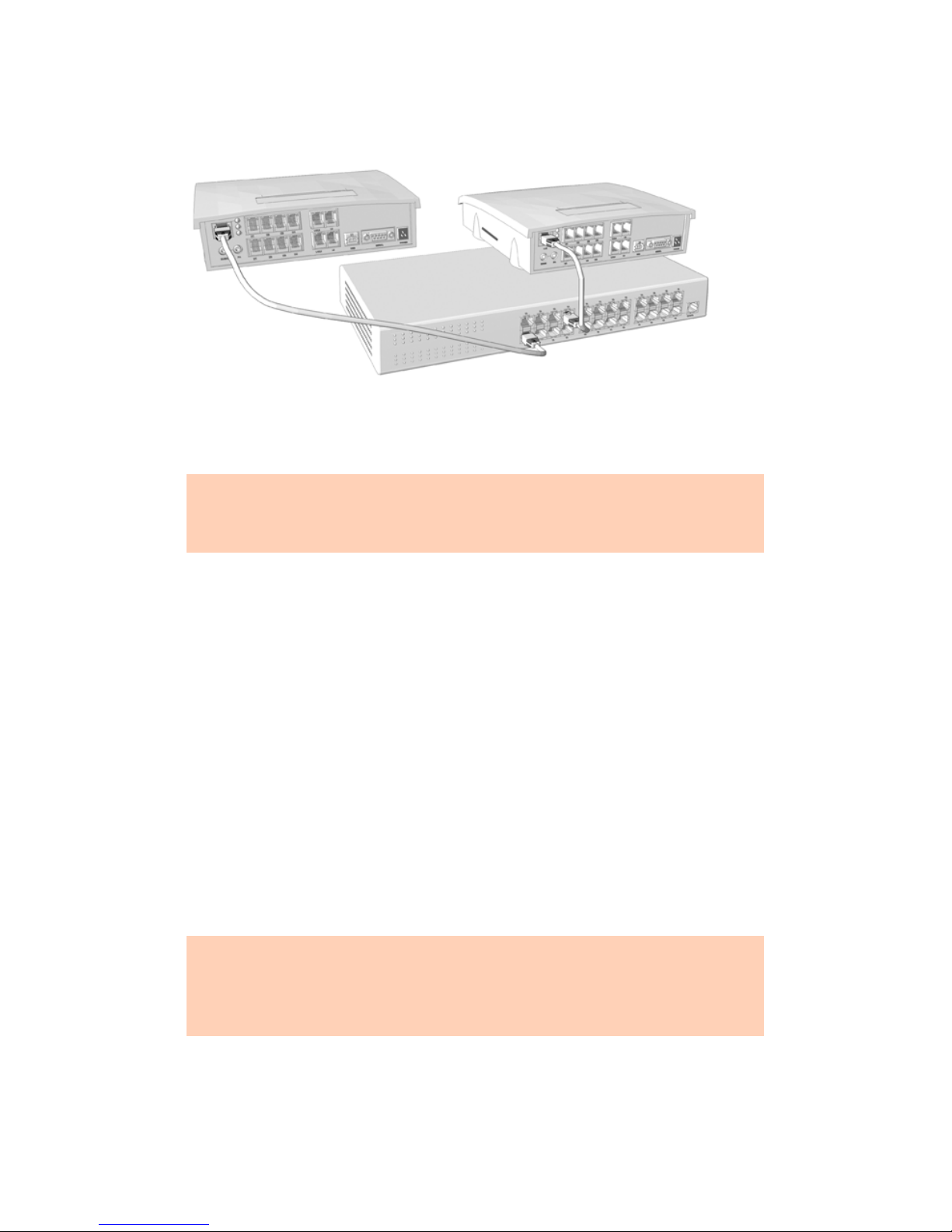
1.5 USING 2 OR MORE TALKSWITCH UNITS ON A LAN
If you have one TalkSwitch unit, ignore this section and proceed to
Chapter 2: TalkSwitch Configuration.
1.5.1 Connecting 2 or more TalkSwitch units to a LAN
TalkSwitch units with a LAN port can be networked together on the same LAN.
Ensure you have the appropriate firmware on all units before adding them to
the LAN. Check http://global.talkswitch.com/ for the latest updates.
We recommend integrating your phone system and your existing LAN with an
Ethernet switch. A switch provides direct communication between TalkSwitch
Note: Users of a TalkSwitch without a LAN port may skip the rest of this
chapter and continue with Chapter 2: TalkSwitch Configuration.
Note: Any time TalkSwitch is being configured, it is ‘locked’ to prevent
other computers or persons using a phone from configuring changes at
the same time. If you leave the software open for longer than 1 hour,
TalkSwitch unlocks itself to allow configuration changes.
Page 17
TALKSWITCH INSTALLATION 9
units, thus keeping the TalkSwitch voice-over-LAN data isolated from other
data on the network.
Connect up to four TalkSwitch units (2 are shown in this illustration) to the
LAN switch or switched hub.
1.5.2 Setting the Unit ID for the first time
When TalkSwitch units are shipped from the manufacturer, they are
programmed with Unit ID 1. If two or more units are placed on the same LAN
with the same Unit ID number, it causes a conflict. TalkSwitch indicates this
by flashing all the line lights on the front panel of the units that have the
conflict.
To resolve the conflict, assign a different Unit ID each of the units. Pick up a
telephone handset connected to one of the extension ports on the
TalkSwitch unit you want to assign a different Unit ID to. You immediately
hear a system prompt indicating that there is a conflict and a new Unit ID
needs to be chosen. Select an available Unit ID between 2 and 4.
The system indicates that the update was successful and the front panel
lights stop flashing after several seconds. When none of the front panel ‘Line’
lights are flashing, all the units are ready for network use.
Note: TalkSwitch unit enclosures are not designed for stacking. We
recommend wall-mounting units in a horizontal row to maximize airflow
and keep the units from overheating.
Note: No IP information is required to configure TalkSwitch since it does
not use the TCP/IP protocol for voice traffic over the LAN.
IP configuration is required for remote management or VoIP once the
system has been configured.
Page 18

10 TALKSWITCH USER GUIDE • UK & IRELAND
1.5.3 Changing the Unit ID
To change the Unit ID, the configuration software must be closed!
Press from a Local Extension to enter command mode.
Enter a password if necessary and dial 0 0 .
The system responds with the Unit ID of that particular TalkSwitch. In
command mode, use any of the following commands:
1.5.4 How unit IDs affect system extension numbers
When more than one TalkSwitch is connected to a LAN in networked mode,
the extensions and voicemail have different numbers based on the Unit ID
assigned to the TalkSwitch unit they belong to.
The extensions and voice mailboxes affected by the new numbering system
are listed in the table below.
None of the Extension Ring Groups are affected They are global to the entire
system. It doesn’t matter if there are one or four TalkSwitch units on a LAN,
Unit ID Touch Tone Command
1
01
2
02
3
03
4
04
Unit ID 1 Unit ID 2 Unit ID 3 Unit ID 4
Local
Extensions
111-118 121-128131-138141-148
Remote
E x t e n s i o n s
211-218221-228231-238241-248
Local
M a i l b o x e s
111-118121-128131-138141-148
Remote
M a i l b o x e s
211-218221-228231-238241-248
General
M a i l b o x e s
410-41942
0-429430-439440-449
#
#
#
#
#
#
Page 19

TALKSWITCH INSTALLATION 11
there will always be 10 Extension Ring Groups with the extension numbers
300-309.
1.5.5 Keep track of the lines and extensions
To keep track of the extensions and lines connected to each TalkSwitch, label
each unit with its Unit ID. It simplifies matters when you need to add or
remove extensions and lines.
If the TalkSwitch units are located in a room away from the extensions and
you need to identify the units, there is a utility in the configuration
software that allows you to identify each unit by flashing the lights on the
front panel. Open the TalkSwitch Configuration software. To check details of
the TalkSwitch units on the LAN, click the ‘View System Information’ link on
the initial window below the TalkSwitch image. Select the Unit ID to verify.
Click the Identify button and observe the flashing LEDs. The lights stop
flashing when you click the ‘Close‘ button or when 5 minutes have elapsed.
1.5.6 Optimizing the system for networked use
TalkSwitch has been designed to operate optimally when in a networked
state. Here are a few items that have been designed for better network use:
Configuration Settings
All units are cloned with identical settings. In the event that a unit has
‘disappeared’ off the network (adapter unplugged, LAN connection
disconnected, LAN failure etc.), the system can still handle the calls, since it
retains the configuration settings of the ‘missing’ unit. In the event an
extension or voice mailbox cannot be reached, the caller hears a system
prompt to the effect: “The extension you are trying to reach is currently
unavailable, please try again later.”
Outgoing Line Hunt Groups
By default, when two or more units are on a LAN, the system tries placing
calls out on the same TalkSwitch unit the call originates from. This avoids
using a line across the LAN on another unit, which helps to minimize the
LAN traffic and optimizes the opportunity for all inbound calls to connect
across the LAN if required.
Auto Attendants
There are a total of 9 Auto Attendants that are shared by all units on the
LAN. When an Auto Attendant is recorded on any unit, it is then
automatically copied to all other units on the LAN. This design minimizes
LAN traffic and also provides functionality back-up in case a unit or units
have ‘disappeared’ off the network (adapter unplugged, LAN connection
Page 20

12 TALKSWITCH USER GUIDE • UK & IRELAND
disconnected, LAN failure etc.). In this event, all units can still answer
inbound calls with the same Auto Attendant messages).
Voicemail
All Local Extension and Remote Extension Voicemail data is stored on the
unit where the extensions normally reside. For example, all greetings,
directory names and voicemail messages for extensions 121-128, 221-228 and
mailboxes 420-429 are stored on the TalkSwitch with Unit ID 2. If a unit is
completely filled with voicemail messages, new messages will not be stored
on other units. The system will simply not accept anymore messages for
mailboxes belonging to that unit. If you need more memory, TalkSwitch
Memory Cards can be purchased from your reseller. You can also use the
Voicemail Memory Manager to view the memory usage of each TalkSwitch unit
and each mailbox.
Page 21

TALKSWITCH CONFIGURATION 13
2.1 INSTALL THE TALKSWITCH
CONFIGURATION SOFTWARE
Insert the TalkSwitch CD into your CD drive. The Install program starts
automatically.
If you prefer to use Windows Explorer:
Double-click the My Computer icon.
Double-click the CD-ROM/DVD drive.
Double-click the Startscreen.exe file.
Follow the instructions on the screen.
Configuration software system requirements:
• PC running Windows XP/2000
• 120 MB free hard disk space
• 128 MB RAM
• An available USB or Serial port (for 24 models)
• An available Ethernet port (for 48 models)
• 800 x 600 minimum video resolution
If you are having problems retrieving the settings from TalkSwitch, please
check Appendix A: Help and Troubleshooting.
Important: The latest version of the TalkSwitch software can also be
downloaded from the TalkSwitch website
http://global.talkswitch.com. Select the country or region.
CHAPTER 2
TALKSWITCH CONFIGURATION
Page 22

14 TALKSWITCH USER GUIDE • UK & IRELAND
2.2 RUNNING THE TALKSWITCH SOFTWARE
After the installation is complete, double-click the TalkSwitch icon. If
TalkSwitch is currently connected to the same network as your PC, the
configuration software detects and retrieves the settings from TalkSwitch
automatically. If TalkSwitch is not yet connected, or is connected via the USB
or Serial port, the following screen displays with different configuration
options.
Connection Type:
Note: If your TalkSwitch is already connected with a USB cable,
disconnect the unit before you install/upgrade software. Reconnect the
USB cable to TalkSwitch when the configuration software is installed.
Serial Select when a serial cable is used to connect the system to a PC.
Serial is only supported with models equipped with Serial port
(Serial cable must be purchased separately)
Ethernet Select when system is connected to PC over a LAN. Ethernet is
only supported with models equipped with a LAN port.
USB Select when a USB cable is used to connect the system to a PC.
(USB cable is supplied with units not equipped with a LAN port)
Internet Select when system is connected to over the Internet and the
required router ports has been opened to allow remote access to
the system Internet (supported by models equipped with a LAN
port)
File Select to edit a configuration file saved on the PC.
TalkSwitch without a LAN port
TalkSwitch with a LAN port
Page 23

TALKSWITCH CONFIGURATION 15
Button — Restore Firmware
This button is only available/active if a firmware update has failed. Click it
to start the TalkSwitch Firmware Update procedure and follow the
instructions. For information on Firmware updates, refer to section 3.8 —
Upgrading the TalkSwitch Software and Firmware.
2.3 SYSTEM CONFIGURATION
2.3.1 The configuration screen
The configuration screen consists of the following parts:
1. Menu Items
2. Configuration Navigation (expandable): Controls the display in the
configuration window
3. Configuration Window: Displays configuration information and
TalkSwitch image.
4. View System Information:
Click this link to view each TalkSwitch unit’s MAC address, IP address,
hardware version and firmware version.
5. Region: Indicates the region where TalkSwitch is intended to operate
X
Y
Z
[
\
Page 24

16 TALKSWITCH USER GUIDE • UK & IRELAND
2.3.1.1 File Menu
2.3.1.2 View Menu
2.3.1.3 Tools Menu
Note: Context sensitive help information is available for each option in
the configuration software. Rest your mouse cursor over any control for a
second or two and the information related to that control pops up.
Open... Opens existing configuration files from the PC. Default
configuration files are included with the software.
TalkSwitch backs up to a file called “LastSavedConfig.dat”
every time you save settings to TalkSwitch.
Save to
TalkSwitch
Saves the current configuration to TalkSwitch.
Save to
File...
Saves the current configuration to a file.
Exit Closes the Configuration.
Retrieve
Settings
Retrieves settings from TalkSwitch connected to the PC.
Update
Firmware....
This action updates the firmware. For more details on
upgrading the TalkSwitch Firmware, see section 3.8.
Tool Bar Toggles the toolbar on/off
Status Bar Toggles the status bar on/off
Memory
Usage
Voicemail: Displays a dialog box showing internal memory
usage for Voicemail messages.
Auto Attendant: Displays a dialog box showing internal
memory usage for Auto Attendant messages.
Voicemail
Manager
Displays a dialog box with options to check the status of all
Voicemail, delete a mailbox password and reset mailboxes to
factory default.
Terminal
Window
Displays a command line interface. This option is useful for
troubleshooting in conjunction with technical support.
Page 25

TALKSWITCH CONFIGURATION 17
2.3.1.4 Help Menu
To access TalkSwitch documents in PDF format (user guides, quick guides,
references etc.), go to:
Start Menu > Programs > TalkSwitch > Documentation.
2.3.2 Configuration Navigation
The Configuration Navigation organizes all the configuration topics within
folders. The following is a brief description of each configuration folder:
Call Logging
Output
Real-time to Serial Port: TalkSwitch can output call detail
records to a PC connected to a Serial port.
Store to file on TalkSwitch: TalkSwitch can store call detail
records to a file stored on TalkSwitch. This file can be
viewed/retrieved from a web browser.
Defaults Select this option to reset the current page or the entire
configuration back to defaults.
Reboot
TalkSwitch
Prompts you to save the configuration. The reboot takes 25
seconds.
About
TalkSwitch
Configuration
Utility...
Displays the TalkSwitch software version number,
TalkSwitch firmware version number and Copyright
information.
Support on the
Web...
Launches your browser and links you to our support
site.
About
TalkSwitch
This link displays version information about the TalkSwitch
software. It also displays new voicemail messages, the time
and date and the current mode.
System
Information
This folder allows you to configure the system setup.
(i.e. activates lines, extensions, VoIP, music-on-hold).
Voicemail This folder allows you to configure each individual voice
mailbox and some global settings for the voicemail
system.
Call
Handling
This folder allows you to configure how to handle incoming
calls. It allows you to setup your Auto Attendants and
individual call handling for each line and distinctive ring
number for both operating modes.
Page 26

18 TALKSWITCH USER GUIDE • UK & IRELAND
2.3.2.1 Configuration considerations connecting multiple units to a LAN
When two or more units are connected to a LAN and are set up for network
use, you can configure all the connected units via the Serial or the USB port
to one of the TalkSwitch units, or to a PC connected to the same LAN as the
TalkSwitch units.
When two or more TalkSwitch units are connected to the same LAN, they are
designed to act like a single phone system. For example, if you have two
TalkSwitch units with LAN ports connected on the same LAN, the system will
function as a single system supporting 8 PSTN lines, 16 local extensions and
16 remote extensions.
Notice that on some configuration pages, there are up to 4 tabs across the
top. They allow you to select the TalkSwitch in the group.
2.3.3 System Information
Click the next to System Information to expand it. Each item is described
in the 2.3.3 sub-paragraphs.
Call Back/
DISA
Configure TalkSwitch’s Call Back and DISA features in this
folder. Both of these features reduce your
company’s long distance expenses.
Options Configure advanced settings In this folder (audio controls,
troubleshooting and various operating options).
Note: Specific details describing the configuration for the use
of features related to the TalkSwitch in a networked
configuration, are preceded by the icon below. If you have a
single Talkswitch, you can skip these sections in the guide.
Note: Specific details describing the configuration or the use
of features related to the TalkSwitch models with VoIP lines,
are preceded by the VoIP icon. If you have a TalkSwitch
without VoIP, you can skip these sections in the guide.
Note: The configuration screens may slightly vary by model.
Page 27

TALKSWITCH CONFIGURATION 19
2.3.3.1 Administration
This screen allows you to assign a System name and Administrator password
for TalkSwitch. The Administrator password gives access to all configuration
options. The password that is entered is used at configuration start-up and
throughout Touch Tone configuration.
System Name: For tracking purposes, a system name can be assigned.
System
Password:
To activate the use of a system password, enter a 4- to
8-character numeric password. The password is also used
to gain access to the system using a touch-tone phone.
If you do not want a password leave the field blank. To
delete a password, enter the existing password. Click on
the password field again but do not enter anything and
click ‘Ok’.
For TalkSwitch models with VoIP lines, the system name
or extension names can be used to appear as Caller ID
information for all outgoing VoIP calls.
Note: Sections 2.3.3.2 and 2.3.3.4 only apply to models with a LAN port.
Owners of models without LAN ports can go to section 2.3.3.5 —
Telephone Lines.
Page 28

20 TALKSWITCH USER GUIDE • UK & IRELAND
2.3.3.2 IP Configuration
Configure TalkSwitch IP settings:
Click on System information (to expand)
Click IP Configuration.
The Radio button “Obtain IP and DNS information automatically” is selected.
Note: An administrator password must be set to avoid unauthorized
access to system configuration, including external access to system
commands.
Location Settings
Subject to the system model, a Location field may display in the System
Information Administrator screen. If the field is shown, set it to the
country where the system is being used. If different service providers are
identified for the country, select the service provider to which the system’s
telephone lines will be connected. Note that setting or resetting this
parameter will change the system setting to the default values required for
the country or service provider. The Location setting is shown in the
bottom right hand corner of all configuration folder windows. If the
Location field is not available on the Administrator page, the system is
preconfigured for the location shown in the bottom right hand corner of
the window.
This section applies to models with a LAN port when VoIP or remote
configuration will be used. There are two methods of configuring the IP
settings: automatic and manual.
Page 29

TALKSWITCH CONFIGURATION 21
System IP Settings section
If you have a DHCP (Dynamic Host Configuration Protocol) server and your
TalkSwitch unit(s) is (are) connected to the LAN, all fields are filled with the
correct information.
Public WAN IP Address
Type of public WAN IP address for Internet Connection:
Select dynamic if your public IP address is a dynamic IP address from
your Internet Service Provider (ISP). If you are unsure if your connection
is dynamic or static, leave this option set to ‘dynamic’. When set to
dynamic, TalkSwitch checks your public IP address every 5 minutes. If it
changes, TalkSwitch automatically updates to the correct information to
manage VoIP calls properly.
Current public WAN IP address
When you select the public IP address type ‘dynamic’, this entry shows
the current public IP address and is not editable. If the public IP address
is ‘static’, you enter it here.
Public WAN IP address-checker server name
When you select the public IP address type ‘dynamic’, this entry shows
the current server name for the IP checker utility. If the public IP address
type is ‘static’, no information is required. The default location is
checkip.talkswitch.com. There is an IP checker application running on
the server that responds to requests from TalkSwitch units for the public
IP address at its location.
Fully Qualified Domain Name
A Fully Qualified Domain Name (FQDN) is required if this location acts as
the SIP Server and does not have a static public IP address from your
service provider. You can obtain FQDNs for free at www.dyndns.org.
Page 30

22 TALKSWITCH USER GUIDE • UK & IRELAND
Download one of the applications specified on the site. It needs to run on
a PC connected to the same LAN to update the DNS servers.
The radio button ‘Use the following IP and DNS information’ is selected
System IP Settings section
If there is no DHCP server present, the following fields need to be completed
if you plan on using the VoIP capabilities of the TalkSwitch.
Unit n IP Address:
Assign an available static IP address to each TalkSwitch unit, where ‘n’
refers to the unit ID (1-4). If you use a DHCP server, you need to reserve
an IP address for each TalkSwitch unit. To reserve an IP address, you need
the MAC address of each unit. See section 2.3.2.1 for details on checking
the MAC address.
Page 31

TALKSWITCH CONFIGURATION 23
Subnet Mask:
Enter the subnet mask for the LAN. If you have a DHCP server running,
this information is obtained automatically.
Default Gateway:
Enter the IP address of the gateway on your network. A gateway is a
hardware device (i. e. router/NAT) that connects the office network to
the Internet. The gateway allows you to share a DSL, cable modem or
other Internet connections with all of the computers and IP devices in
your office network.
Preferred DNS Server:
Enter the preferred DNS server’s IP address. This is also known as the
primary DNS server. DNS is a Service that maintains information about a
portion of the Domain Name System (DNS) database and responds to DNS
queries for determining an IP address resolved from a Domain Name. For
more information about DNS, see Chapter 5: VoIP Information.
Alternate DNS Server:
Enter the alternate DNS server’s IP address if applicable. This is also
known as the secondary DNS server.
Public WAN IP Address (see previous section)
2.3.3.3 VoIP Configuration
This section deals with configuring your TalkSwitch for VoIP.
Page 32

24 TALKSWITCH USER GUIDE • UK & IRELAND
Expand the System Information folder and click VoIP Configuration.
In the “TalkSwitch Profile” tab
TalkSwitch has a built-in SIP Server Proxy/Registrar/Redirect server. This
facilitates the configuration and maintenance for multi-branch and
teleworker applications. One location needs to be assigned as the SIP Server
to manage call requests between VoIP locations and the other locations need
to register with the SIP Server location.
To facilitate calls between TalkSwitch locations, we recommend that you use
TalkSwitch location codes 250-299 as phone numbers for each of your VoIP
numbers. Do not assign duplicate numbers between any two locations.
This TalkSwitch location is the Proxy/Registrar:
If this location is designated to be the Proxy/Registrar Server, check this
box. When it is enabled and other SIP devices are registered with this
system, any calls made within the group contact this device to resolve the
destination location. Once the destination is resolved, the call is made
directly from the source location to the destination location.
The TalkSwitch Registrar supports Digest authentication. The Digest
mechanism is a challenge/response protocol in which the client presents
its credentials in response to a challenge from the server. This method of
authentication is very secure. To enable authentication, select ‘yes
(digest)’ from the drop-down list under Registrar Authentication.
Page 33

TALKSWITCH CONFIGURATION 25
Proxy Server Name:
If this location is acting as the Proxy Server, it is filled in automatically.
If this location is not the Proxy Server, then enter the IP address or
domain name associated to the Proxy Server. If the Server is using a
different port number than the default, specify the port number after a
colon at the end of the domain or IP address.
Example 222.234.432.234:5061
Registrar Server Name:
If this location is acting as the Registrar Server, it is filled in
automatically. If this location is not the Registrar Server, enter the IP
address or domain name associated to the Registrar Server. If a VoIP
enabled TalkSwitch unit is acting as the Server, both, the Proxy Server
Location and Registrar Server Location fields should have the same
information. If the Server is using a different port number than the
default, specify the port number after a colon at the end of the domain
or IP address.
Example VoIP .domain.com:5061
Outbound Proxy:
If TalkSwitch is being provisioned with a VoIP Service Provider, enter the
Outbound Proxy associated with the Service Provider.
Realm/Domain:
If this location is the Proxy/Registrar, you can assign a realm/domain
name to this unit. (for example, ‘domain.com’). Note: This field is only
required when TalkSwitch is being provisioned with a VoIP service
provider. In this case, enter the realm/domain associated with the
service provider. If this unit is not the Proxy/Registrar, it must have the
same realm as the Registrar Server.
User Name and Password Section
User/Account:
If this location is the Proxy/Registrar and you have enabled
authentication, assign a User/Account name to this unit that will be
required by all other locations for registration purposes. If this unit is
not the Proxy/Registrar and if authentication is required, it must have
the same User/Account name filled in as the Registrar Server.
Page 34

26 TALKSWITCH USER GUIDE • UK & IRELAND
Password:
If this location is the Proxy/Registrar and you have enabled
authentication, assign a password to this unit. This password is required
by all other locations for registration purposes. If this unit is not the
Proxy/Registrar and authentication is required, it must have the same
password as the Registrar Server.
VoIP Numbers
TalkSwitch offers the flexibility to share VoIP numbers with the TalkSwitch
network and a Service Provider. You can reserve lines for use with one or the
other depending on requirements.
VoIP numbers available for use with the TalkSwitch network:
By default, there are no restrictions on VoIP number use between the
TalkSwitch and Service Provider profiles. If you need to give priority of
availability to calls being placed in/out of this location on the TalkSwitch
VoIP network, select an upper limit for the number of lines.
Maximum number of VoIP numbers for incoming calls:
The maximum number of VoIP numbers available is determined by how
many lines are available (shared) with the TalkSwitch VoIP network. For
business reasons, you might want to make all lines available for incoming
calls and restrict the number of lines used for outgoing calls.
Maximum number of VoIP numbers for outgoing calls:
The maximum number of VoIP numbers available is determined by how
many lines are available (shared) with the TalkSwitch VoIP network. For
business reasons, you might want make all lines available for incoming
calls and restrict outgoing calls so that the likelihood of incoming calls
being missed.
View Registrar Entries (button)
If this location is the Registrar Server, click this button to view which
systems are registered with the Registrar Server.
View Registration Status (button)
Click this button to view whether or not this system is registered with the
designated Registrar Server.
Page 35

TALKSWITCH CONFIGURATION 27
In the “Service Provider Profile” tab
A VoIP enabled TalkSwitch can register with VoIP service providers to support
calls using their service. Check with TalkSwitch for the list of Service
Providers that support TalkSwitch inter operability.
Service Provider Name:
Enter the name for your VoIP service provider. The name will be displayed
elsewhere in the configuration software in areas related to VoIP service.
Proxy Server Name:
Enter the IP address or domain name associated with the Proxy Server. If
the Server is using a different port than 5060, specify the port number
after a colon at the end of the domain or IP address.
Example, 222.234.432.234:5061
Registrar Server Name:
Enter the IP address or domain name associated with the Registrar
Server. If the Server is using a different port number than 5060, specify
the port number after a colon at the end of the domain or IP address.
Example, VoIP.domain.com:5061
Page 36

28 TALKSWITCH USER GUIDE • UK & IRELAND
Outbound Proxy:
Enter the Outbound Proxy (if required) associated with the Service
Provider.
Realm/Domain:
Enter the Realm/Domain (if required) associated with the Service
Provider.
VoIP numbers
The descriptions for the VoIP numbers under the TalkSwitch Profile tab are
the same for the items below.
VoIP numbers available for use with this Service Provider:
Maximum number of VoIP numbers for incoming calls:
Maximum number of VoIP numbers for outgoing calls:
View Registration Status (button)
Click this button to view if this system is registered with the designated
Registrar Server.
2.3.3.4 PSTN analogue telephone Lines
To configure telephone lines go to the System Information and Telephone
Line folder. Select the tab for the telephone line to be configured. “Line
Detected” shows if the telephone line was detected when the system
configuration was last retrieved. To update the detected status select File
and Retrieve Settings from the menu. Save any changed settings before
retrieving the system’s current settings.
Note: If the units are networked, you need to configure the options for
all the units. At the top of the window, select the tab for each TalkSwitch
unit (labeled ‘TalkSwitch 1’, ‘TalkSwitch 2’, etc....) and follow the
instructions below.
Page 37

TALKSWITCH CONFIGURATION 29
In the “Phone numbers” section
In the “Telephone company services” section
Click on Activate Line to enable the telephone line port. Enter the normal
telephone number for the telephone line as the Main Number.
If your are using a Distinctive Ringing service for alternative telephone
numbers from your telephone service provider check either Distinctive Ring
1 or Distinctive Ring 2 as required and enter the matching telephone
numbers. When incoming calls are detected with these distinctive ringing
patterns they will be handled as separate telephone lines and can be setup
with different call handling (e.g. routed to a FAX machine at specific
extension).
The distinctive ringing patterns are as follows:
Distinctive Ring 1 Two ring bursts per cycle of ringing (where normal
ringing is a single ring burst per cycle); OR a single
ring burst per cycle of ringing (where normal ringing
is two ring bursts per cycle of ringing)
Distinctive Ring 2 Three ring bursts per cycle of ringing
Select any of the telephone company services that have been activated on
the telephone line. See Appendix B for details of compatibility with
telephone company services.
Page 38

30 TALKSWITCH USER GUIDE • UK & IRELAND
3-Way Calling/Conference
TalkSwitch can work with a service to forward calls to Remote Extensions or
other external phone numbers while using the same line (Same Line
Connect). You can use this service as an option for bridging calls to
external numbers when calling into TalkSwitch from the outside. If you
find that you are having difficulties with line volume levels when
forwarding calls to Remote Extensions or using DISA, use 3-way calling to
forward calls.
Transfer and Clear (Centrex/Plexar transfer)
TalkSwitch can clear the line after forwarding a call to a Remote Extension,
if your telephone line supports this feature. If you enable this feature
without having the service, callers are disconnected when TalkSwitch
attempts to forward their call to the Remote Extension.
Call Waiting
Check this box if you have a Call Waiting service on the current line. It is
strongly recommended that you remove this service from your line(s), since
there is no way for TalkSwitch to answer a second call on the same line
while it is handling the first call. You may want to consider adding the
Hunt/Rollover service to your lines instead.
Caller ID
Check this box if the current line provides Caller ID information. TalkSwitch
will pass along the Caller ID information to the selected extensions. Also,
TalkSwitch can use the time information provided by Caller ID to update
TalkSwitch’s internal clock.
Telephone Company Voicemail
Check this box if you are subscribed to a Telephone Company Voicemail
service.
Hunt/Rollover/Busy Forwarding
Check this box if the current line is associated with a Line Hunt or Line
Rollover service from the Telephone Company. In general, any lines that
belong to a Hunt/Rollover group should be configured to handle calls the
same way.
Note: Section 2.3.3.5 only applies to models with VoIP trunks.
Page 39

TALKSWITCH CONFIGURATION 31
2.3.3.5 VoIP Numbers
The VoIP enabled TalkSwitch unit supports 4 VoIP lines per unit. Up to 12 VoIP
phone numbers can be assigned for each unit so that unique call handling
scenarios can be configured for up to 12 numbers. For example, you might
assign a general number for customers to reach the main Auto Attendant
greeting and configure up to 11 other numbers so that the inbound calls ring
straight through to specific extensions in the office.
Activate phone numbers as required. If you had previously assigned numbers
in the first slot for each of the VoIP numbers and performed a firmware
update, the new layout will place these numbers in VoIP slots 1,4,7 and 10.
Phone numbers need to be associated with the TalkSwitch network or a
Service Provider network.
In the “TalkSwitch Profile” section:
All VoIP numbers are active when the system is first configured. Phone
numbers need to be assigned so that inbound VoIP calls can be handled
according to the configuration parameters set for VoIP numbers under the
Call Handling section 2.3.5. Phone numbers can be one or more digits in
length.
Page 40

32 TALKSWITCH USER GUIDE • UK & IRELAND
Phone numbers 250-299 have special functionality with TalkSwitch. These
numbers can be dialed directly from any extension or Auto Attendant and
are routed automatically via VoIP to the destination with the number
assigned to one of its ports. Part of the role of an administrator is to keep
track of all phone numbers assigned to each location to prevent duplicate
numbers in multiple locations. We recommend that you use these numbers as
it will facilitate calling from extensions and the Auto Attendants.
In the “Service Provider Profile” section
All VoIP numbers are active when the system is first configured. Phone
numbers need to be entered exactly as provided by the Service Provider. For
the United States and Canada, the Country code is 1. Enter the area code and
phone number.
Enter a Username and Password. Every phone number has a unique Username
and Password.
2.3.3.6 Line Hunt Groups
There are a total of 9 Line Hunt Groups that control outbound call line
selections. These Line Hunt Groups are used by the Local and Remote
Extensions and the DISA feature. Each Hunt Group can support several line
choices and attempt to use an available line in the order that they are listed
(Lines to Hunt) for that Hunt Group. These settings have no effect on
incoming calls.
Default setup:
Select a Line Hunt Group and enter a unique name to identify this Hunt
Group elsewhere in the configuration software.
Under ‘Set Line Hunt Group’, select the Line Type. If you wish to use this
Hunt Group to access telephone lines, select ‘Phone Lines’. To use this Hunt
Group to access VoIP numbers, select ‘VoIP numbers’.
Hunt Group 9: selects any available telephone line
Hunt Group 81: selects telephone Line 1
Hunt Group 82: selects telephone Line 2
Hunt Group 83: selects telephone Line 3
Hunt Group 84: selects telephone Line 4
Hunt Group 88: selects any available VoIP number (only applies
to units with VoIP trunks)
Page 41

TALKSWITCH CONFIGURATION 33
Under ‘Set Line Hunt Group’, select the lines you wish to add to the Hunt
Group by checking the box next to the line.
2.3.3.7 Automatic Route Selection and Toll Restriction
Automatic Route Selection (ARS) allows outgoing calls to be redirected to
different telephone lines or VoIP trunks and hence network operators based
on the leading digits dialed to access geographical areas, mobile operators or
services. For example, use this feature to block all long distance calls or
redirect long distance calls to VoIP.
Toll Restriction allows calls to be blocked based on the geographical area
code, mobile operator, service number or access code dialed.
The Automatic Route Selection (ARS) table is programmed by the system
administrator with the leading digits of calls to be re-routed or blocked.
TalkSwitch routes outgoing calls through Line Hunt Groups to telephone
lines or VoIP trunks, dialing the outgoing Line Hunt Group access codes “9”
or “81” to “88” or directly when Direct Line access is enabled on an
extension. When ARS is activated for any Line Hunt Group and the caller has
dialed, their dialed digits are compared to the leading digit entries in the
Automatic Route Selection (ARS) table.
Note: If multiple TalkSwitch units are connected to the LAN,
a check box is enabled, so that outbound calls always hunt
the lines on the unit where the extension is connected. This
minimizes network traffic between units.
Page 42

34 TALKSWITCH USER GUIDE • UK & IRELAND
The comparison is based on finding the maximum number of leading digits
that match. If a match is found the call follows the action specified in the
ARS table. The action can be to block the call with an announcement or
re-route it to an alternative Line Hunt Group. The Line Hunt Groups are setup
to direct calls to specific telephone lines or VoIP trunks connected to
different network service operators. If there are no matching entries in the
ARS table, the call proceeds without any redirection or restriction to the Line
Hunt Group whose access code was originally dialed by the caller or specified
for direct line access.
Planning Automatic Route Selection and Toll Restriction
• Identify the leading digits of the numbers for the calls to be routed or
blocked.
• Identify which telephone lines and VoIP trunks are connected to different
networks and services.
• Identify which extensions’ calls you wish to route or block.
Configure Line Hunt Groups (also, see section 2.3.3.6)
Ensure that the Line Hunt Groups are configured.
In the TalkSwitch Configuration software, click System Information ->
Line Hunt Groups. We recommend that each network service provider’s
telephone lines or VoIP trunks are assigned to a separate line hunt group.
You can define a name for each line hunt group and adjust the order in which
the telephone lines will be used for outgoing calls.
• Type a name into the Line Hunt Group name: field (up to 20 characters).
• Click the check box next to the lines you wish to include in the line hunt
group.
• Click/highlight the telephone line you wish to move.
• Click the Move Up or Move Down button to reflect the desired selection
order.
Overflow calls to another network when preferred lines are busy
Calls can overflow to an alternative network operator’s lines when the
preferred lines are busy. For example, if the first two lines are reserved for
local calls and both those lines are busy, you can allow outgoing calls on the
next line, even thought that line might be your preferred long-distance
connection.
• Click the check box next to the line(s) where you want the calls to
overflow if the preferred lines are busy.
Page 43

TALKSWITCH CONFIGURATION 35
• If necessary, click Move Up or Move Down to change the order of the
lines.
Entering Leading Digits and Assigning Actions
What are leading digits?
• Leading digits are the first digit or first several digits of an international
access code, country code, area code or phone number.
• Leading digits can be anywhere from 1–11 characters.
• Leading digits can include numeric characters 0–9 and *.
ARS will route or block calls according to the leading digits you define and
the actions you chose in the TalkSwitch Configuration under System
Information -> Auto Route Selection.
• Enter the leading digits you wish to route or block in the Leading Digits
field.
The leading digit for long-distance is ‘1’. As soon as you dial ‘1xxx-xxx-xxxx’,
the system recognizes that you are making a long-distance call.
To place an overseas call, you would dial ‘011’, followed by the country code,
the area code and the phone number (i.e. 011 xx xx xxx-xxxx). Once you
dial ‘011’, the system recognizes that the caller is placing an overseas call.
‘011’ are the leading digits.
Page 44

36 TALKSWITCH USER GUIDE • UK & IRELAND
• Select the desired Action (route to a specified line hunt group or block
calls) from the corresponding pull-down list.
Example:
Note: The entries that you specify for ARS match the dialed digits with
the longest leading digits entry. If the numbers dialed match the digits
that you specified in table shown above, the call is routed to a line hunt
group or blocked according to the Action you selected.
• If you dial ‘9’ followed by a phone number that does not start with ‘1’,
‘01’ or ‘01161’, you access an outside line. The number is automatically
routed according to the configuration of line hunt group 9.
• If you dial ‘9’ followed by ‘1’, a 3-digit area code and
a 7-digit number, you access a line for long-distance calls in North
America, as defined in line hunt group 82.
• If you dial ‘9’ followed by ‘01’, the call is blocked. At the extension, you
hear a prompt stating "You are not permitted to dial this number" and
then a normal dialtone.
• If you dial ‘9’ followed by ‘01161’, an area code and a phone number,
you access a line for calls to Australia, as defined in line hunt group 83.
Page 45

TALKSWITCH CONFIGURATION 37
Set Local Extension Hunt Group Access
By default, all line hunt groups for each local extension are enabled. If you
wish to restrict access to some line hunt groups, you need to disable the line
hunt groups at the local extension.
• Open the TalkSwitch Configuration software.
• Select System Information
• Click on Local Extensions.
• Click the Hunt Group Access button.
• Remove the check mark (by clicking it) next to the line hunt groups you
do not want to allow for that local extension.
Repeat these steps for all your local extensions. When you allow access to line
hunt groups that have ARS activated, the calls are routed through ARS
Direct Line Access
If you enable Direct Line Access on an extension, calls placed from that local
extension are routed to the line hunt group you designated. If ARS is enabled
on that line hunt group, the calls are routed through ARS.
Page 46

38 TALKSWITCH USER GUIDE • UK & IRELAND
Additional Notes
Emergency Access Numbers
The emergency access numbers, shown in the Emergency Service Section
of the ARS configuration window, are always allowed through ARS, even
if the line is blocked. These numbers are dependant on the region and
change based on the country/location settings.
Password Protection
We recommend that the administrator’s password protection is enabled
when you use automatic route selection and toll restriction. Enable the
password protection in the TalkSwitch Configuration software under
System Information -> Administration.
Enter a 4–8 character numeric password.
Telephone Line Three-Way Calling Services
The use of the telephone company's three-way calling service is not
recommended when ARS is used. The TalkSwitch ARS has no control over
routing of calls through this feature.
Call Detail Record Logging (CDR)
You can retrieve the records generated by the calls that are made through
the TalkSwitch system. Please refer to Call Detail Record Logging
TalkSwitch Quick Guide.
Page 47

TALKSWITCH CONFIGURATION 39
Automatic Route Selection Examples
2.3.3.8 Fax Information
If you have a dedicated fax line or a Distinctive Ring number for a fax ma
shine associated with a line, choose the fax number in the list. If you don’t
have a line dedicated for inbound faxing, select ‘None’.
If you do not see your fax number in the list, make sure you have activated
the appropriate line or Distinctive Ring number in the TalkSwitch
Configuration software, under System Information -> Telephone Lines.
Select the extension number where you have your fax device connected. For
example, if you have your fax machine connected to E8 on the rear of
TalkSwitch unit 1, select extension number 118.
Blocking international calls, with exceptions
Leading Digits Action Objective
00
00
Block Calls
Hunt Group 81
International calls are restricted.
North American calls are allowed.
08 Hunt Group 81 Redirect calls to mobile operators with
access codes 08 to different line, that may
be equipped fixed GSM phone services.
Call Redirection Advisory: Use of the Automatic Route Selection and Toll
Restriction features does not imply any guarantee whatsoever by
regulatory authorities, your network operator(s), TalkSwitch or its
distributors and resellers, with regard to the accuracy of these features
and that the use of such a features may not be accepted by the network
operator in any disputes which may arise regarding the accuracy of any
subscriber’s telephone account.
Page 48

40 TALKSWITCH USER GUIDE • UK & IRELAND
2.3.3.9 Local Extensions
Local Extensions are phones or devices connected to any of the extension
ports at the back of TalkSwitch. See sections 1.3 and 1.4 for more details on
connectivity.
Select the extension(s) you wish to configure.
Local Extensions are activated with the associated Voice mailbox by default.
Voicemail boxes for each Local Extension can be de-activated in the
Voicemail section in the System Information folder.
Note: If your fax machine is connected to E8 on a TalkSwitch with Unit
ID 2, the fax extension number is 128. If you have a dedicated fax line or
number, your fax machine should be connected to an extension port on
the same TalkSwitch unit where the fax line/number is connected.
By default, when both, a dedicated line and fax extension have been
selected for the first time, the software automatically configures the
incoming call handling properties for that line to ring only the fax
extension that you have specified.
Note: If you have multiple units configured together on the same LAN,
each unit has a separate tab at the top of the folder. Local extensions are
numbered 1nx, where n is the number of the unit on the LAN and x is the
extension.
Page 49

TALKSWITCH CONFIGURATION 41
Caller ID Information section
Last Name/First Name:
Enter the first and last name of the person associated with the
extension. The last name is required if the person is included in the ‘Dial
by Name’ directory listing used by the Auto Attendant. The person using
that extension must also record their name for the directory by following
the instructions below the name fields. The name entered displays on the
Caller ID of other Local Extensions during intercom calls.
For TalkSwitch VoIP calls, use: [this number]
Select the number you want to display at the remote location when VoIP
calls are placed from this extension. If ‘Default VoIP Number’ is selected,
the phone number associated with the outgoing VoIP port is used. This
selection makes the most sense if your VoIP numbers have been
configured to handle all inbound calls in the same way.
For [Service Provider] VoIP calls, use: [this number]
Select the number you want to appear at the remote location when VoIP
calls are placed from this extension. If ‘Default VoIP Number’ is selected,
then the phone number associated to the outgoing VoIP port will be
used. This selection makes the most sense if your VoIP numbers have
been configured to handle all inbound calls in the same manner.
Phone Type
If you have a TalkSwitch phone set connected to this extension, then select
the model of phone. TalkSwitch sets have some integrated features that will
not work unless the proper phone is specified. Features include intercom
paging and group paging over the speaker on the TS-200, TS-400 and TS-600
phones and message waiting counter.
The models of telephone sets available will vary by market.
Direct Line Access (button)
Direct line access allows you to configure the extension to access a specific
Hunt Group automatically for outbound calls when the extension goes off
hook. For example, you may have a fax machine connected to this extension
and don’t want to reprogram the speed dial phone numbers. In this case, you
select ‘Direct line access’ and choose the appropriate Hunt Group. As soon as
Page 50

42 TALKSWITCH USER GUIDE • UK & IRELAND
the fax goes off hook, TalkSwitch hunts the specified lines for an available
line. This feature allows users to avoid dialing extra digits to access a line.
Hunt Group Access (button)
This is used if you want to permit or restrict specific Hunt Group access to
the extension. Click the button and organize the appropriate line Hunt
Groups that are permitted for this extension (by default, extensions have no
restrictions)
.
2.3.3.10 Remote Extensions
With TalkSwitch’s Remote Extensions, you can have calls forwarded directly
from your office to any phone number you choose. Your cell phone, pager or
any out-of-office number becomes a ‘Remote Extension’ of your office
system. You can choose to screen callers. If you are unavailable or choose not
to accept calls, they can be transferred back to your office (e.g. to voicemail
or another extension), or, forwarded to another out-of-office telephone
number (e.g. to a business partner’s cell phone) depending upon the Call
Cascade configuration.
For details on how to use Remote Extensions, see sections 3.3.1 and 3.3.2.
Once your remote extensions are configured, calls can be forwarded by the
Auto Attendant or transferred by someone in your office by dialing the
Remote Extension number. There are 8 Remote Extensions available per
TalkSwitch unit.
Warning: When using Direct Line Access, the telephone company line dial
tone is first available when you pick up the handset. The following
features are only available from the TalkSwitch internal dial tone:
• Intercom Calling,
• Hold Retrieve,
• Line Hunt Groups,
• Voicemail Retrieval/Access,
• Call Pick Up,
• P.A. Access,
• Parked Call Retrieval,
• Do Not Disturb functions and
• entering Command Mode.
To obtain an internal dial tone at an extension which has Direct line
Access enabled, dial Recall after going off hook.
Note: If a TalkSwitch has Unit ID 2, the Remote Extension numbers are
221–228. Unit ID 3 has remote extensions 231-238 and Unit ID 4 has
241-249.
Page 51

TALKSWITCH CONFIGURATION 43
Choose a Remote Extension to configure. You must enter a phone number in
order for the extension to be considered active by the system.
Last Name/First Name:
Enter the first and last name of the person associated to the extension.
The last name is required if the person is to be included in the ‘Dial by
Name’ directory listing used by the Auto Attendant. The person using
that extension must also record their name for the directory following the
instructions listed below the name fields.
Forwarding Information
Remote phone number:
Enter the phone number of the Remote Extension (no specific prefixes are
required other than area codes for long-distance calls). Enter the number
the same way you are dialing it from a regular phone. You may use digits
0–9, space, comma, dash, and .
Connect using:
Select the line Hunt Group that TalkSwitch will use to connect the
Remote Extension. This is an advantage if you have an inexpensive longdistance plan set up for the lines in Hunt Group 84. You may want to use
this Hunt Group for your long-distance Remote Extensions.
Use Same Line Connect
Check this box to allow incoming calls to use the same line of the original
incoming call when forwarding it to the Remote Extension. This feature
allows only one line to be used when forwarding incoming calls to a
Remote Extension. It can only be used when the line of the originating
#
*
Page 52

44 TALKSWITCH USER GUIDE • UK & IRELAND
incoming call has 3-Way Calling/Conference or Transfer service (Centrex/
Plexar). If the line does not have any of these services, the call will be
forwarded using the Hunt Group chosen in the “Connect using:” section.
If you have a ‘Transfer and clear’ service on your line(s) and want to have
TalkSwitch clear lines after forwarding calls to Remote Extensions, you
need to enable ‘Clear telephone line after call transferred’ in the Transfer
Options page under ‘Options’. If your service requires the remote end to
answer the call before the transfer can be made, use the ‘play accept/
reject prompt’ or ‘play caller’s name first’ screening option set on the
‘Answered at ext.’ in the Remote Extension section under Call Handling.
Check with your telephone company if you are uncertain which setting
works best for you.
2.3.3.11 Extension Ring Groups
There are a total of 10 Extension Ring Groups available for your use. Ring
Groups are extensions 300 to 309. By default, extension 300 is configured to
ring all extensions.
Different uses for Extension Ring Groups
Send calls to specific groups of employees. For example, if you have a
company with several departments, you can configure Extension Ring Group
Note: Remote Extensions do not have the ability to transfer calls manually
when using ‘Same line Connect’.
Note: When using Same line Connect, callers hear silence while they are on
hold. The callers are on hold at the Telephone Company and not at
TalkSwitch. If you want callers to hear music while they are on hold for calls
forwarded to Remote Extensions, do not use Same line Connect. It is best to
experiment with different settings in order to decide what works best for
your configuration.
Note: Remote extensions are designed to operate when the extension is on
the network of local major telephone service providers. The feature may not
function correctly with some telephone and mobile operators’ networks,
especially for international telephone numbers and mobile phones when
roaming internationally. If the remote extension’s service provider includes
“prompted ring back” (an announcement offering a call back when the line
busy), this service must be disabled from the remote extension’s line. The
remote extension feature does not operate on lines with “colour-me” ring
tones. See Appendix B for compatibility with telephone company calling
features.
Page 53

TALKSWITCH CONFIGURATION 45
300 for the Sales Department, to ring extensions 111, 112, 113, and 114.
Ring Group 301 might be for Technical Support, ringing extensions
115 and 116.
Identify types of calls by different ring patterns
Example: You are the president of a company and you don’t want to handle
calls from the general public, yet you want to be alerted when important
colleagues try to contact you. Your regular Local Extension may be 111 for
most people, but you can configure an Extension Ring Group 300 to ring your
extension with a different ring pattern. You tell your colleagues to choose
extension 300 at the Auto Attendant or ask to be transferred to extension
300 when speaking to someone in the office. Without being subscribed to
Caller ID, you can tell by how your phone rings if you consider the caller to
be important.
Select the Extension Ring Group (300-309) you would like to configure.
Activate it.
In the “Set Ring Group” section
Select each extension you wish to add to that Ring Group. Repeat this
process for each of the Extension Ring Groups you want to activate.
Ring pattern:
Choose how you want the phone(s) to ring for the Ring Group.
Page 54

46 TALKSWITCH USER GUIDE • UK & IRELAND
2.3.3.12 On-hold/Ringback
If you wish to have callers listen to music or advertising while they are on
hold, enable Music on Hold in this tab.
On-Hold Settings
There are 3 options for when callers are placed on hold.
1. The default setting is to play ‘double beep’ tones to callers when placed
on hold. No additional configuration is required.
2. If you have a music source connected to the MUSIC port, select
‘Play music whose source is connected to the MUSIC port’.
3. TalkSwitch can play a music-on-hold file once loaded on the system.
This file must be in 8KHz, 8bit, mono, u-law format. You can convert
MP3 and other file formats using a utility like Audio Converter or
Ripper. Download a converter at: www.audioi.com. Check the volume
of music on hold with a test call. Adjust the levels as required. This
setting is not real-time. Save the configuration to TalkSwitch and
make another test call.
Transfer Settings
Select if you would like your callers to hear ringing, music or the ‘double
beep’ tones while they are transferred.
Note: If you connect a music source to the Music port but do not enable
Music on hold, the caller hears both, music and a beep sound on hold.
When the caller makes a selection at the Auto Attendant to go to an
extension with call screening enabled, s/he will hear ringing and music.
Page 55

TALKSWITCH CONFIGURATION 47
2.3.4 Voicemail
2.3.4.1 Local Extension Voicemail
This section deals with the internal voicemail system included with
TalkSwitch. It allows you to activate Local, Remote and General voice
mailboxes and to change global settings to the voicemail system. We
recommend to expand the memory for voicemail and auto attendants with a
memory card, available at www.talkswitch.com or at your local reseller. For
details on how to use voicemail, see Chapter 3: Using TalkSwitch.
All Local Extensions are activated with a voicemail box by default.
Note: If you have more than one unit connected to the LAN
and you are using an external music source, you need to
connect the source to all units. Obtain a 1/8” audio splitter
available at most electronics stores. If you are using a.wav
file loaded to TalkSwitch, no additional steps are necessary. The music file
is copied to all units on the LAN.
Page 56

48 TALKSWITCH USER GUIDE • UK & IRELAND
Mailbox Option section
Play announcement only:
If you want to use a local extension mailbox for informational purposes and
prevent callers from recording messages, check the ‘Play announcement only’
box.
Load Greeting (button):
You can load a pre-recorded voicemail greeting from your PC to TalkSwitch.
The file must be an 8khz, 8-bit, mono µ-law .wav file.
In the Voicemail Notification Settings section
Under the Dialed Notification tab, set the manner in which you want to be
notified when new messages arrive.
Remote Phone:
If you want to be notified at another location when new messages arrive,
use Remote Phone Notification. Enter the phone number of the cell
phone or location where you want to be notified.
Notification Settings (button):
If a caller presses ‘0’:
Select what action to take when a caller presses ‘0’ during Mode 1 or Mode
2 while in a voice mailbox.
go to voice mailbox Callers are transferred to the specified
mailbox.
go to local extension Callers are transferred to the specified local
extension.
go to remote extension Callers are transferred to the specified remote
extension.
go to ring groups Callers are transferred to the specified ring
group.
play announcements Callers are transferred to the specified
announcement.
go to auto attendant Callers are transferred to the specified
Auto Attendant.
perform no action No action is performed when ‘0’ is pressed.
Page 57

TALKSWITCH CONFIGURATION 49
Select Notification Settings to specify how you want TalkSwitch to handle
notification calls.
Pager:
Click the Pager check box if you want to be notified by pager when new
messages arrive. Activate the feature and enter the pager number and the
numeric message to be displayed on the pager.
Configuration Notification Options (button)
Define how TalkSwitch dials out of your office when notifying you of a
voicemail. If the first connection is not successful, define the number of
times and the intervals TalkSwitch continues to attempt the connection.
When you choose to be notified by pager and remote phone, TalkSwitch
ensures that both locations have been contacted before finishing the
notification process.
Dial notification phone number using:
Select the Hunt Group you want to use for the Remote Phone and Pager
Notification calls. It allows you to adjust the number of rings before it
aborts the attempt and follows the parameters listed in the next section.
If attempt unsuccessful, try again:
These parameters control how many times TalkSwitch tries to notify the
Remote Phone or Pager before it aborts the entire notification attempt.
You can specify the time interval between attempts.
Under the Message Waiting Light tab, set a message waiting light to
indicate when a message has been received for an extension. Select the local
extensions in your system where the light is activated when a message
arrives. The message waiting light turns on at the extension associated with
a local mailbox by default.
Page 58

50 TALKSWITCH USER GUIDE • UK & IRELAND
This feature works with FSK MWI message compatible telephone sets.
Stuttered dial tone is also provided.
2.3.4.2 Remote Extension Voicemail
Remote Extension voicemail is similar to the Local Extension voicemail.
Ensure that the remote extension has been enabled so that you can activate
its voicemail.
Please refer to section 2.3.4.1 for information on the following.
Go to voicemail box; Go to local ext.; Go to remote ext.; Go to ring
groups; Play announcement only or perform no action.
Load Greeting button;
Voicemail Notification Settings tab;
Remote Phone Notification;
Notification Settings; Pager Notification;
Message Waiting Light;
Configuration Notification Options;
Dial notification phone number and If attempt unsuccessful.
If a caller presses ‘0’:
Page 59

TALKSWITCH CONFIGURATION 51
2.3.4.3 General Voicemail
General Voicemail is similar to both Local and Remote Extension Voicemail.
These are generic mailboxes used for general purposes like messages for a
sales team or a technical support group.
Please refer to section 2.3.4.1 for information on the following.
Go to voicemail box; Go to local ext.; Go to remote ext.; Go to ring
groups; Play announcement only or perform no action.
Load Greeting button;
Voicemail Notification Settings tab;
Remote Phone Notification;
Notification Settings; Pager Notification;
Message Waiting Light;
Configuration Notification Options;
Dial notification phone number and If attempt unsuccessful.
If a caller presses ‘0’:
Page 60

52 TALKSWITCH USER GUIDE • UK & IRELAND
2.3.4.4 Global Settings
Any changes made to Global Settings affect all system voice mailboxes.
Global Message Waiting Indicator
This option is helpful if you use a limited number of voice mailboxes. When a
new message is left in any active voice mailbox, the Power/Data light pulses
very slowly to indicate that there is at least one new message in one of the
mailboxes. Once all new messages have been heard, this light returns to the
solid state (default state).
Mailbox Settings
‘When listening to voicemail...’
This option controls the order in which messages are played back when you
listen to voicemail. The default setting plays back messages starting with the
newest message and working back to the oldest. This setting is the most
convenient. People store several saved messages and don’t want to skip
through all these messages every time they want to listen to newer ones.
‘When pager/remote mail notification...’
This controls whether the system pages or calls your remote phone for every
new message or only the first new message received in the voice mailbox.
‘Remove blank and hang up messages automatically
Only remove messages shorter than’ (specify 1–5 seconds).
Check this box if you tend to get several messages where callers don’t leave a
message and hang up. Not clearing the short messages gives you the
advantage of listening to the Caller ID information at the end of the message
to identify callers (Caller ID service required from your telephone company).
Page 61

TALKSWITCH CONFIGURATION 53
View Mailbox Data (button)
View the details for each voice mailbox and announcement followed by a
summary. This tool is useful for managing the voicemail resources of the
system.
Reset Mailboxes (button)
Example: An employee has left the company and all greetings, messages and
settings for a particular mailbox have to be reset. If you simply need to
delete a password, use the Voicemail Manager located under the Tools menu.
2.3.5 Call Handling
2.3.5.1 Modes
The use of Modes allows you to run different call handling configurations at
different times. For example, you may want forward calls to your cell phone
during the day and to your voicemail after business hours. Modes are
Page 62

54 TALKSWITCH USER GUIDE • UK & IRELAND
switched manually or automatically (with Automatic Mode Switching). Name
the modes since names are displayed elsewhere in the configuration software
whenever Modes are used.
To use the Automatic Mode Switching feature, activate it by clicking ‘Use
Automatic Mode Switching’. Set the start times for each mode. If you want
TalkSwitch to change modes more than twice in one day, you can activate up
to two extra mode changes.
2.3.5.2 Auto Attendant
The Auto Attendant greets callers and tells them which number(s) they
should press on their telephone keypad to reach a particular extension,
person, message, or department. Callers can dial Local Extensions (1xx),
Remote Extensions (2xx), Extension Ring Groups (300-309), Voicemail (to
both leave messages and access messages), access Call Back, access DISA and
enter Command mode directly to make changes to the system configuration.
400 series mailboxes can be dialed at the Auto Attendant without
Warning: The mode cannot change if you are logged into the
configuration tool at the time of the scheduled mode switch.
Note: If you do not want to use Automatic Mode Switching, you can
switch modes manually in the software or through a telephone using
touch tone commands. Enter command mode by dialing and your
password if required. Dial any of the following commands and press
to confirm.
31 Change TalkSwitch to mode 1.
32 Change TalkSwitch to mode 2.
30 TalkSwitch tells you what mode it is currently using.
#
#
Page 63

TALKSWITCH CONFIGURATION 55
pressing first. This is useful for providing ‘virtual’ Extensions associated
with a mailbox for telecommuters or other part-time staff.
You can record or load up to 9 different Auto Attendants with a total
combined time of 30 minutes (share with voicemail) or expand memory up to
9 hours using a TalkSwitch Memory card.
You can record the Auto Attendants from any Local Extension or remote
phone using touch-tone commands. To load a pre-recorded message, see Load
Auto Attendant later in this section.
Record Auto Attendant messages
Pick up any Local Extension (dial into TalkSwitch from an external source at
the Auto Attendant) and enter command mode by pressing . If you have
an Administrator password, enter it. Begin entering the touch tone
commands listed below. TalkSwitch ‘walks’ you through the recording. After
entering a command, press to confirm the entry before continuing with
other commands or exiting command mode. To exit, press or hang up.
Note: When two or more units are networked (models with LAN ports
only), they share the same 9 Auto Attendants. When an Auto Attendant
message is recorded on any TalkSwitch unit, it is automatically copied to
all the other TalkSwitch units on the same LAN. This feature helps reduce
network traffic and allows any system to continue functioning even if
another unit loses power or is disconnected from the LAN.
#
#
#
*
Page 64

56 TALKSWITCH USER GUIDE • UK & IRELAND
Example:
1. From the local extension go off hook and press to enter command
mode, then dial 4 1 .
2. After the tone, record your Auto Attendant message. Press when you
are done.
3. Press 5 1 to listen to your recording.
Recording Auto Attendants from an out-of-office phone
1. Dial into TalkSwitch and wait for the Auto Attendant message.
2. Once the Auto Attendant is playing, use the same keypad commands as
listed above. If Password Protection is enabled, you are prompted for
your password.
At the Auto Attendant, perform the following actions
The caller can select the single-digit options ‘0’, ‘1’, ‘2’, ‘3’, ‘4’ or ‘5’.
If the caller selects ‘0’ then:
The ‘0’ option is used to direct callers to a receptionist. You may want to
configure this option to ring a Local Extension. For an after hours Auto
Auto
Attendant
Record
message
Play
message
Erase
message
1 4151041
2 4252042
3 4353043
4 4454044
5 4555045
6 4656046
7 4757047
8 4858048
9 4959049
Note: If the Administrator password is enabled, you need to enter the
password after you press the first time to enter command mode.
#
#
#
#
#
Page 65

TALKSWITCH CONFIGURATION 57
Attendant, use this option to forward calls to a Remote Extension for
emergency purposes or direct callers to a voice mailbox.
If the caller selects ‘1’, ‘2’, ‘3’, ‘4’ or ‘5’ then:
TalkSwitch can perform one of several actions in the table below at the
selected Auto Attendant.
perform no action If you don’t want to use a particular option,
set it to perform no action.
go to voice mailbox You can configure any single digit option to
send a caller immediately to voicemail. Select
the appropriate mailbox.
go to local extension You can provide a single-digit option to ring a
particular extension, as opposed to 3 digits.
go to remote ext. You can provide a single-digit option to ring a
particular remote extension, as opposed to 3
digits (3 for Ring Group 300).
go to ring group you can provide a single-digit option to ring
an Extension Ring Group.
go to auto attendant TalkSwitch can direct callers to multiple levels
of auto attendants. For example, you might
want to use your main auto attendant to
provide language options like “press 1 for
English, 2 for Spanish.” Then you configure
option 1 to go to auto attendant 2 (English
version) and option 2 to go to auto attendant
3 (Spanish version).
queue at ring group This directs calls to a group of Extensions and
keeps callers on hold until a member of the
ring group is free to take the call, similar to
Uniform Call Distribution.
play announcement You can set any unused voicemail to ‘play
announcement only’. Announcements are
useful for providing directions, business hours
and/or other information. Inform callers that
they can press to return to the Auto
Attendant.
go to directory If you want to enable callers to locate
employee extension numbers by last name,
select this option.
*
Page 66

58 TALKSWITCH USER GUIDE • UK & IRELAND
If a fax call is detected then:
If TalkSwitch detects a fax call (identified by the CNG tones emitted from the
fax), it can route it to a Local Extension. If you do not want to use fax
detection, have TalkSwitch perform no action.
After the Auto Attendant has finished playing and no selection was made
within x seconds then
If no selection is detected at the specified Auto Attendant, TalkSwitch can
route the call to any Local or Remote Extension, Ring Group, Voice mailbox,
Auto Attendant, Announcement, dial by name directory, queue the caller or
hang up. This feature is included for callers who do not have a touch-tone
phone or for a fax call where the calling fax machine does not emit a CNG tone.
It can also be used to forward calls immediately after the Auto Attendant
answers the call. You can specify the length of time after the Auto Attendant
has finished playing before it performs the ‘no selection’ action.
The digits 6, 7, 8 and 9 are not available as programmable options. They are
used for other system features.
If 6 is dialed
If you press ‘6’ at the Auto Attendant, you are able to configure and use
Auto and Prompted Call Back. See section 2.3.6.1 for more details about
configuring Call Back and section 3.7.2 for details on using Call Back.
Note: TalkSwitch waits 1.5 seconds after your caller inputs a digit before
following with another digit. If another digit is not received, TalkSwitch
follows the action set for the single digit. This allows caller to use ‘1‘ for
the auto attendant option and ‘111‘ as an extension number.
Note: Fax calls are detected by a series of beeps called a CNG tone (not all
fax machines emit a CNG tone). If a fax machine sends this tone while
trying to establish a connection to a fax machine connected to
TalkSwitch, TalkSwitch will handle the call accordingly. As a result,
TalkSwitch is able to detect those fax calls and route them to the fax
machine. To guarantee the reception of every fax, we recommend the use
of a ‘Distinctive Ring Number’ added to one of your lines for fax calls.
TalkSwitch can then handle all fax calls consistently. See section 2.3.3.8.
Note: If you dial ‘6’ at the Auto Attendant and no Call Back is enabled,
TalkSwitch answers with the prompt: “I am sorry, there is no matching
entry for these digits”.
Page 67

TALKSWITCH CONFIGURATION 59
If 7 is dialed
TalkSwitch uses 7 to precede PBX Extensions of another Centrex or PBX
system. If TalkSwitch is not connected to another system, 7 is inactive. If
TalkSwitch is connected to another PBX system, see section 2.3.5.4 for
more details.
If 80 – 88 or 9 is dialed
If you press ‘80 – 88 or 9’ at the Auto Attendant, you access DISA if it has
been permitted. See section 2.3.6.3 for more details on configuring DISA
and section 3.7.1 for details on using DISA.
Utilities for an auto attendant
Record Instructions (button)
Click this button to display a dialog box showing the instructions on how to
record and playback an Auto Attendant using a telephone. No adjustments are
required for the recording volume. TalkSwitch adjusts the recording volume for
optimal recordings.
Load Auto Attendant (button)
Click this button to display a dialog box with instructions on how to load an
Auto Attendant using a pre-recorded .wav file. If you want to have Auto
Attendants professionally recorded, make sure to specify that the files have to
be 8KHz, 8bit, mono, and saved as a µ-law format .wav file.
Page 68

60 TALKSWITCH USER GUIDE • UK & IRELAND
Erase Instructions (button)
Click this button to display a dialog box showing the instructions on how to
erase an Auto Attendant using a telephone. It is a good idea to erase unused
Auto Attendants. They share the memory with voicemail.
View Auto Attendant Time Usage
To view the amount of time used by
all Auto Attendants, go to the main
menu Tools -> Memory Usage
-> Auto Attendant.
You may have unused Auto Attendant
messages. Delete them to free up
memory.
2.3.5.3 PSTN analogue telephone Lines
This section describes how TalkSwitch handles incoming calls based on the
incoming line and ring cadence (distinctive ring numbers).
On an incoming call during mode 1 or 2
Select a line to configure and select Mode 1 or Mode 2 where you want
TalkSwitch to use these settings. If you entered the phone number in the
Telephone Lines section under System Information, the number displays on
the corresponding button.
Note: With the use of a memory
card, you can extend the time for
voicemail and Auto Attendant
recordings to up to 9 hours.
Page 69

TALKSWITCH CONFIGURATION 61
Ring Extensions only (no Auto Attendant is played)
If you don’t want the Auto Attendant to answer calls on this line, select
this option. All the Local Extensions are set to ring immediately during
an inbound call by default. No Call Cascade actions (such as voicemail)
can be performed if you select this option.
Select the Local Extensions you would like to ring. All activated local
extensions ring by default. If you require certain Extensions to ring in a
sequence (i.e. one extension rings first, then another one on the 2nd
ring), click the ‘Adjust Sequence’ button to configure.
Play Auto Attendant
This option plays an Auto Attendant for incoming calls. Select the
appropriate Auto Attendant (1–9) and the number of rings before the
Auto Attendant answers.
Go to Voice Mailbox
If you do not want to use an Auto Attendant but want the call to go to a
voice mailbox, select the appropriate mailbox. The caller always hears
Note: If you call on any line, TalkSwitch answers after 15 rings with a
generic Auto Attendant so that you can still access the system to make
configuration changes, change modes, access voicemail or dial
Extensions.
Page 70

62 TALKSWITCH USER GUIDE • UK & IRELAND
one more ring than the number of rings you select. TalkSwitch uses the
first ring to determine the ring type and to support Caller ID
information.
Adjust Sequence.. (button)
This section controls how the Extensions will ring before the Auto Attendant
answers the call.
• If you have chosen the Auto Attendant to answer calls immediately, this
section does not require configuration and is grayed out.
• If the Auto Attendant is set to answer after 1 or more rings, configure
when specific Extensions ring before the Auto Attendant answers.
• If no Auto Attendant is selected to answer on the specified line, specify
when particular Extensions will ring up to 9 times. Remember
that no calls go to voicemail unless you first have an Auto Attendant
answer.
2.3.5.4 VoIP Numbers
First, select a VoIP number to configure. Then select the appropriate mode
for which you want TalkSwitch to use these settings. If you entered the
phone number in the VoIP Numbers section under System Information, the
number will appear on the corresponding button.
Remember: Callers are only directed according to settings for an Auto
Attendant. Calls do not follow the Call Cascade settings of any of the
Local Extensions programmed to ring before the Auto Attendant answers.
This section deals with how TalkSwitch with VoIP trunks will handle
incoming VoIP calls.
Page 71

TALKSWITCH CONFIGURATION 63
Descriptions for VoIP numbers and Telephone Lines (section 2.3.5.3/4) on
the four features below are the same.
Ring Extensions only (no Auto Attendant is played),
Play Auto Attendant or,
Go to Voice Mailbox.
and
Adjust Sequence... (button)
2.3.5.5 Local Extensions — Call Cascade
This section configures the incoming Call Cascade options for the Local
Extensions. The Call Cascade routing options are engaged if the extension is
selected by the caller or if a call is manually transferred to the extension.
Once a call enters an extension’s Call Cascade sequence, the extension
“owns” the call. It does not follow any other extension’s options, even if that
extension is selected in the Cascade sequence. What you see in an
extension’s Cascade sequence is exactly what you’ll get. You can set up the
Call Cascade sequences differently for both scheduling modes (the
scheduling for these modes are set up on the Modes tab).
Page 72

64 TALKSWITCH USER GUIDE • UK & IRELAND
If a call is manually transferred to a Local Extension that is busy, TalkSwitch
follows the Call Cascade options for that extension.
There are 4 different ‘Call Cascade’ situations for Local Extensions.
1. Busy (at extension);
2. No answer (at extension);
3. Answer (at extension, routing when a call is rejected) and
4. Do not Disturb (when turned on at an extension).
For each of these situations, three ‘cascade’ destinations are available to control
how and where you want to handle the incoming call to the extension.
1. Busy tab — routing options when this extension is busy
Cascade options for forwarding calls:
• go to voice mailbox,
• go to local ext.,
• go to remote ext.,
• go to ring group,
• play announcement,
• invoke Call Waiting,
• go to auto attendant,
• queue caller,
• play busy tone (example, if a fax machine is at the extension),
• hang up.
For more information on these features, see Chapter 3: Using TalkSwitch.
Page 73

TALKSWITCH CONFIGURATION 65
2. No Answer tab — routing options if this extension is not answered
after x rings
Select the number of rings and select one of the actions. The action drop
down list is the same as for the Busy tab except that the option ‘play busy
tone” is replaced by ‘keep ringing‘.
3. Answered tab — routing options when this extension answers or ‘rejects’
a screened call
Select ‘play caller’s name first’ to prompt callers who choose this
extension at the Auto Attendant, to record their name. When you answer
the call at the extension, it announces the caller (by playing their
recording). At this point, you can accept the call by pressing or
reroute the call to the Cascade options on this tab by hanging up or
pressing .
Routing/forwarding options for rejected calls:
• go to voice mailbox,
• go to local ext.,
• go to remote ext.,
• go to ring group,
• play announcement,
• go to auto attendant,
• hang up.
In the case you select ‘hang up’, TalkSwitch plays the following prompt:
“I’m sorry, that extension is unavailable at this time. Please try again
later.”
4. Do not Disturb — routing options when this extension has engaged the
‘Do not Disturb’ feature.
The Do not Disturb feature is toggled on or off by dialing 62 from a
Local Extension handset. Cascade options include forwarding calls to a:
• go to voice mailbox,
• go to local ext.,
• go to remote ext.,
• go to ring group,
• play announcement,
• go to auto attendant,
• hang up.
When ‘Do not Disturb’ is enabled, you hear ‘Do not disturb on’ before the
dial tone as a reminder that no calls ring at your extension. You may dial
during this prompt.
#
*
*
Page 74

66 TALKSWITCH USER GUIDE • UK & IRELAND
2.3.5.6 Remote Extensions — Call Cascade
Remote Extension Call Cascade works principally the same way as the local
Extension Call Cascade. Please refer to section 2.3.5.5 and substitute the
word Remote for Local. The Remote Extension Call Cascade does not have a
‘Do not Disturb’ option.
The Call Cascade routing options are only engaged if the extension is chosen
from the Auto Attendant or if a call is manually transferred to the extension.
Once a call enters an extension’s Call Cascade sequence, the extension
“owns” the call. It will not follow any other extension’s options, even if
chosen in the Call Cascade sequence. What you see in an extension’s Call
Cascade sequence is exactly what you’ll get. You can set up the Call Cascade
sequences for both modes (the scheduling for these modes are set up in the
Modes tab).
For Remote Extensions, there are 3 different ‘Call Cascade’ options. For each
of these options, you can control how and where you want the incoming call
to the extension handled.
Note: In the Cascade sequence, only choosing an extension (Local,
Remote or Ring Group) allows you to choose an option in the next
selection. Any other selection is considered an end-of-call option. Note
that the last selection in the Cascade sequence only allows the choice of
an ‘end-of-call’ option. This is done so there is no chance of a caller being
“looped” within the system.
Page 75

TALKSWITCH CONFIGURATION 67
1. Busy tab — routing options when this extension is busy
Cascade options for forwarding calls:
• go to voice mailbox,
• go to local ext.,
• go to remote ext.,
• go to ring group,
• play announcement,
• go to auto attendant,
• play busy tone (example, if a fax machine is at the extension),
• hang up.
For more information on these features, see Chapter 3:
Using TalkSwitch.
2. No Answer tab — routing options if this extension is not answered
after x rings
Select the number of rings and select one of the actions. The action drop
down list is the same as for the Busy tab except that the option ‘play busy
tone” is replaced by ‘keep ringing‘.
3. Answered tab — routing options when this extension answers or ‘rejects’
a screened call
Select ‘play caller’s name first’ to prompts callers who choose this
extension at the Auto Attendant, to record their name. When you answer
the call at the extension, it announces the caller (by playing their
recording). At this point, you can accept the call by pressing or
reroute the call to the Cascade options on this tab by hanging up or
pressing .
Routing/forwarding options for rejected calls:
• go to voice mailbox,
• go to local ext.,
• go to remote ext.,
• go to ring group,
• play announcement,
• go to auto attendant,
• hang up.
If you select ‘stay connected’, the Call Cascade options are grayed out.
TalkSwitch can control forwarded calls when prompting is enabled. If you
use one of the prompted methods for this Remote Extension, have Music
on hold enabled and are not using 3-way calling to forward calls to this
Remote Extension, the Call Cascade is seamless to the caller. S/he only
hears music throughout the entire process of trying to locate you.
#
*
Page 76

68 TALKSWITCH USER GUIDE • UK & IRELAND
2.3.5.7 Extension Ring Groups — Call Cascade
Extension Ring Groups — Call Cascade is similar to Local and Remote Call
Cascade (sections 2.3.5.5 and 2.3.5.6).
The Call Cascade routing options are engaged if the Ring Group is selected
from the Auto Attendant or if a call was transferred manually to the Ring
Group. Once a call enters a Ring Group’s Call Cascade sequence, the Ring
Group “owns” the call. It does not follow any other extensions options, even
if that extension is selected in the Call Cascade sequence. What you see in a
Ring Group’s Call Cascade sequence is exactly what you’ll get.
For Ring Groups, there are 3 different ‘Call Cascade’ options. For each of these
options, you can control how and where you want the incoming call to the
extension handled.
1. Busy tab — routing options when this extension is busy
Cascade options for forwarding calls:
• go to voice mailbox,
• go to local ext.,
Note: If a call is forwarded to a Remote Extension from a Call Cascade
sequence and has ‘play caller’s name first’ or ‘play accept/reject prompt’
enabled, the Remote Extension hears “This is Call Cascade...” instead of
“This is Call Forward...”. This indicates to you that the call is rejected and
sends the caller to the next Call Cascade option of the extension that
forwarded the call and not follow the Remote Extension’s ‘Answer at ext.’
Call Cascade options.
Page 77

TALKSWITCH CONFIGURATION 69
• go to remote ext.,
• go to ring group,
• play announcement,
• go to auto attendant,
• queue at ring group,
• play busy tone (example, if a fax machine is at the extension),
• hang up.
For more information on these features, see Chapter 3:
Using TalkSwitch.
2. No Answer tab — routing options if this extension is not answered
after x rings
Select the number of rings and select one of the actions. The action drop
down list is the same as for the Busy tab except that the option ‘play busy
tone” is replaced by ‘keep ringing‘.
3. Answered tab — routing options when this extension answers or ‘rejects’
a screened call
Select ‘play caller’s name first’ to prompts callers who choose this
extension at the Auto Attendant, to record their name. When you answer
the call at the extension, it announces the caller (by playing their
recording). At this point, you can accept the call by pressing or
reroute the call to the Cascade options on this tab by hanging up or
pressing .
Routing/forwarding options for rejected calls:
• go to voice mailbox,
• go to local ext.,
• go to remote ext.,
• go to ring group,
• play announcement,
• go to auto attendant,
• hang up.
2.3.6 Call Back/DISA
Call Back and DISA act, working together, as your personal long distance
operator. Whether you are across town or around the world, you can place
calls from your office telephone or VoIP number(s), accessing your long
distance savings plan.
#
*
Page 78

70 TALKSWITCH USER GUIDE • UK & IRELAND
You can make a direct call to TalkSwitch, activate Call Bridge and enter the
telephone number you want to dial. TalkSwitch dials the number from your
office telephone or VoIP numbers and connects the two calls together (the
call you made to TalkSwitch and the call TalkSwitch made from your office to
the dialed party). This is how it works:
Step 1:
Call your TalkSwitch telephone number to activate Call Back, then hang up.
Step 2:
TalkSwitch calls you back within 10 seconds. You answer and accept Call
Back. Your Auto Attendant plays if you have one recorded or the TalkSwitch
message will play.
Step 3:
You can now access any TalkSwitch extension, voice mailbox or use DISA to
make calls around the globe just as if you were sitting in your own office.
There are two ways to activate Call Back:
1. Auto Call Back — Auto Call Back is immediate and eliminates the initial
long distance call charge required to activate Call Back.
Before Call Back is activated, all the Call Back settings must be
pre-configured. To use Auto Call Back, dial your office telephone number,
let the call ring twice and hang up and Call Back is activated.
2. Prompted Call Back — Prompted Call Back offers the convenience of
entering or changing your Call Back telephone number and message each
time Call Back is activated.
To use Prompted Call Back, dial your office telephone number. When the
Auto Attendant answers your call, dial ‘6’ to access the Call Back settings
through a series of prompts which allow you to:
a) Enter the telephone number where you would like TalkSwitch to call
you.
b) Record an ‘‘Announced’ message if required. Call Back is activated
right after you initiate Prompted Call Back and hang up. It is
PBX Fraud (unauthorized use of the PBX and access to outgoing
telephone lines):
We recommend that you change Administrator, DISA and Call Back
passwords frequently.
Page 79

TALKSWITCH CONFIGURATION 71
important to remember that a small initial long distance charge is
incurred at your current location when you activate Prompted Call
Back.
2.3.6.1 Auto Call Back
TalkSwitch‘s Call Back/DISA features gives you access to your office-based long
distance savings plan from
anywhere around the world.
You can configure four Auto Call Back numbers. Select an Auto Call Back 1–4.
Click the check box next to ‘Activate Auto Call Back x’ (x represents a number
from 1 to 4).
Number to call back:
Enter the Call Back number exactly as you would normally dial the number
(i.e. do not enter a line Hunt Group in the dialing string).
Use dialing prefix:
If you have to dial the same prefix every time when using Auto Call Back
(i.e. long distance calling card number), enable ‘Use dialing prefix’. Enter
the dialing prefix including any required pauses or feature keys like
or . Use a comma to insert a 2-second pause. For example, if you want
to disable Call Waiting and want to dial a long distance prefix before
dialing the long distance number, enter the following:
Note: Prompted Call Back is not activated in the TalkSwitch configuration
by default. You need to activate Prompted Call Back before you can use
the feature. The Call Back out of the system to the number programmed
always uses the same line that was dialed.
*
#
Page 80

72 TALKSWITCH USER GUIDE • UK & IRELAND
*70,1010555,, This corresponds to 70 for disabling the Call Waiting
feature, a 2 second pause to wait for the new dial tone, 1010555 for the
long distance prefix, and a 4 second pause to wait for the new dial tone
before dialing the long distance phone number.
Number used to trigger Auto Call Back:
Select the line/phone number that you dial when out of the office to
trigger Auto Call Back. TalkSwitch initiates the Call Back using the same
line you initially called. You can make configuration changes to Auto Call
Back by dialing into this phone number only.
Use Password on Call Back:
The password option is designed to give you security and to restrict the
use of this particular Call Back number. Enter a 4- to 8-digit password for
the Call Back. When TalkSwitch calls you back, you are prompted for the
password to accept Call Back.
Use Announced Message:
We recommend this option if the number TalkSwitch calls back is to a
hotel or a location where a third party answers the call. The Announced
Message option allows you to record a message that plays when the call is
initially answered during a Call Back. For example, “Please transfer this
call to Bob in room 307”. The Announced Message can be recorded locally
using an extension handset or remotely by accessing Call Back from the
Auto Attendant. The Record message button gives the instructions as
follows:
Pick up a telephone handset connected to the TalkSwitch and use the
following keypad commands to record the specific Auto Call Back
Announced Message:
1. Press to enter command mode. Enter the password if required.
2. Enter the appropriate command as listed below. After each command,
press to confirm the entry.
Auto Call Back Recording Playback
16171
26272
36373
46474
*
#
#
Page 81

TALKSWITCH CONFIGURATION 73
Allow DISA (Call Bridge):
To allow DISA (Call Bridge) after a Call Back has been accepted, check the
Allow Call Bridge box. You may also restrict the Call Bridge line access by
selecting the Hunt Group Access button. By default, Call Bridge is enabled
when Call Back is activated. You will not be prompted for another
password when you select a Hunt Group at the Auto Attendant.
2.3.6.2 Prompted Call Back
If you are travelling to a location where you do not yet know the phone
number, you can use Prompted Call Back to save on your long distance
charges. For details on using Call Back, see section 3.7.2.
Note: There are 4 Auto Call Back accounts per TalkSwitch unit. If you
need to record an Announced Message for a particular Auto Call Back
account, it must be on the same TalkSwitch unit as the account.
Note: If you need to configure and/or record an Announced Message from
a remote location and do not have the Auto Attendant set up to answer
this Call Back line, you can call your Call Back number and let it ring 15
times. A generic Auto Attendant will answer and you can configure Call
Back by pressing 6.
Note: For a 2 second pause, dial 0 and for a , dial .
When you have completed the entire dial string, press .
*
#
*
#
#
Page 82

74 TALKSWITCH USER GUIDE • UK & IRELAND
Number to call back:
Enter this phone number exactly as you would normally dial the number
from this line (do not enter a Line Hunt Group in the dialing string).
TalkSwitch calls back from the same line the call originated.
Use dialing prefix: (with Call Back number)
If you have to dial the same prefix when using Auto Call Back (for
example a long distance calling card number), enable ‘Use dialing prefix’.
Enter the dialing prefix including any required pauses or feature keys like
or . Use a comma to insert a 2-second pause. For example, if you
want to disable Call Waiting and want to dial a long distance prefix before
dialing the long distance number, enter the following:
*70,1010555,, This corresponds to 70 for disabling the Call Waiting
feature, a 2 second pause to wait for the new dial tone, 1010555 for the
long distance prefix, and a 4 second pause to wait for the new dial tone
before dialing the long distance phone number.
This saves you from entering the same prefix every time you want to set
up an Auto Call Back phone number.
Use Password on Call Back:
The password option is designed to give you security and to restrict the
use of this particular Call Back number. Enter a 4- to 8-digit password for
the Call Back. When TalkSwitch calls you back, you are prompted for the
password to accept Call Back.
Use Announced message:
As described in the Auto Call Back (section 2.3.6.1), we recommend this
option if the number TalkSwitch calls back is to a hotel or a location
where a third party answers the call. The Announced message option
allows you to record a message that plays when the call is initially
answered during a Call Back. For example, “Please transfer this call to Bob
in room 307”.
The Announced Message can be recorded locally using an extension
handset or remotely by accessing Call Back from the Auto Attendant.
The ‘Record message’ button gives the instructions as follows:
Note: When you access Prompted Call Back from out of the office, you
may change this number before initiating a Prompted Call Back. The
benefit of Prompted Call Back is that you do not need to preset the
number before you leave the office.
*
#
*
Page 83

TALKSWITCH CONFIGURATION 75
Pick up a telephone handset connected to the TalkSwitch and use the
following keypad commands to record the Prompted Call Back Announced
Message:
1. Press to enter command mode. Enter the password if required.
2. Enter the appropriate command as listed below. After each command,
press to confirm the entry.
Allow DISA (Call Bridge):
To allow DISA (Call Bridge) when a Call Back is accepted, check the Allow
Call Bridge box. You can restrict the DISA line access by clicking the Hunt
Group Access button. By default, Call Bridge is enabled when Call Back is
activated.
Call Bridge saves money while using Call Back or on its own. It bypasses the
high long distance rates for cell phones.
How to use DISA (Call Bridge):
1. Call into TalkSwitch from any out-of-office telephone.
To record message: 65
To playback message: 75
Note: The call back number shown is always the last number TalkSwitch
dials in the last Prompted Call Back session.
2.3.6.3 DISA
#
#
Page 84

76 TALKSWITCH USER GUIDE • UK & IRELAND
2. At the Auto Attendant message, dial the Hunt Group for which you have
the account password (9 is default). You are prompted for the password.
3. Dial the password and press to access a TalkSwitch telephone line.
4. At this point, you can dial a number the same way as from the office.
Each TalkSwitch unit has four password activated Call Bridge accounts.
Each account can be configured to allow access to certain Hunt Group(s)
when using Call Bridge.
To activate an account, check the ‘Activate Call Bridge’ box and enter a 4- to
8-digit password. Click the ‘Hunt Group Access’ button and assign the Hunt
Groups for this account.
2.3.7 Options
2.3.7.1 Audio Controls
This section deals with the adjustment of volume and system gain controls.
All the controls on this page update TalkSwitch in ‘real time’. This allows you
to adjust levels during a conversation without having to first save the
configuration to TalkSwitch.
Note: Call Bridge account passwords are only valid when using Call Bridge
by itself, not when used in conjunction with Call Back.
#
Line hunt group 80 is used for
‘Same Line Connect’. To enable line
hunt group 80, click the check
box next to ‘Allow the use of Same
Line Connect [by dialing 80]’.
Page 85

TALKSWITCH CONFIGURATION 77
Line Controls
If you need to adjust the volume of conversations through the system, you
can adjust each line individually. The default settings compensate for loss
created by TalkSwitch and a portion of the loss created by your lines. We
recommend that you adjust the level for each line separately, as the
characteristics of each line may vary. These controls only affect the volume
heard by the caller. To calibrate the lines once a line is added or changed,
click the ‘Calibrate Lines’ button.
Extension Controls
These controls allow you to increase or decrease the volume level of calls and
system prompts heard at each extension.
VoIP Codec Selection
All 3 codecs are active by default. The preferred codec is G.729
(approximately 20Kbps bandwidth). For example, if you have a ‘lite’ version
of a broadband service, you do not have enough bandwidth to support G.711
(approximately 100Kbps bandwidth) or G.726 (approximately 50Kbps
bandwidth) codecs. ‘Lite’ connections typically have only enough bandwidth
to support G.729. In this case, uncheck the G.726 and G.711 codecs so that
the system does not attempt to use these codecs when setting up a call.
Page 86

78 TALKSWITCH USER GUIDE • UK & IRELAND
Using these codecs can cause one side of the call to sound ‘choppy’ because
the broadband connection cannot handle the required bandwidth.
Voice Activity Detection (VAD):
A typical voice conversation may contain 35-50 percent silence. If
customers need to conserve bandwidth, we recommend to enable VAD.
When VAD is enabled, voice packets are suppressed during silence (i.e. an
extension is on hold or there is no talking from the extension side of the
conversation).
2.3.7.2 Transfer Options
This section describes TalkSwitch’s actions when calls are transferred
manually.
Transferring a caller to a Local Extension, Remote Extension or
Ring Group
You can specify how transferred calls are handled if their target is a local
extension, remote extension or ring group and if it is busy or doesn’t answer.
You have the choice of TalkSwitch ringing back the extension that
transferred the call or performing the “no answer” or “busy” action of the
extension that the call was intended for. Any changes made in this section
affect the entire system.
Page 87

TALKSWITCH CONFIGURATION 79
Transferring from a Home phone
You can transfer a call from a phone connected in parallel to one of the
incoming TalkSwitch lines (for example, your home phone if you have a
home-based business) to a Local or Remote Extension, Extension Ring Group,
an Announcement, or a Voicemail box. This section allows you to choose
which transfer prefix you would like to use to perform the action. The
transfer prefix ‘wakes up’ TalkSwitch and is considered the equivalent of the
Recall or Link action at a Local Extension. The default prefix is
.
Example: You receive a call on a phone in your home that is not a TalkSwitch
extension and you want to transfer the caller to Remote Extension 215. You
dial , wait for the ‘double beep’, dial 215 and hang up. TalkSwitch
now handles the call. For more details, see section 2.3.7.2.
Transfer and clear
TalkSwitch has the ability to clear lines after a call has been transferred.
Ensure you have this service/feature activated on your line(s). Check under
System Information -> Telephone Lines.
Remote Transfer
Calls that are transferred to a Remote or VoIP Extension, can be transferred
back to another extension or voice mailbox. Dialing to place the
caller on hold, then enter the extension or mailbox number. If this is set to
allow screening calls, dial 4 to complete the transfer. If you want
to cancel the transfer, dial 5. If you have selected ‘Perform a blind
transfer’, the call is automatically transferred and the line is released once
the extension or mailbox number has been entered.
When a call is transferred from a Remote Extension to another Remote
Extension or VoIP Extension, it is always a blind transfer so that three lines
are not tied-up for the transfer.
2.3.7.3 Miscellaneous
All of the following options affect TalkSwitch as a system. Adjust them
according to your needs.
Note: This feature can only be used when forwarding a call to a Remote
Extension or a VoIP location over 2 lines. It cannot be used with
3-Way Calling or Centrex Transfer services.
* *
* *
* *
* *
* *
Page 88

80 TALKSWITCH USER GUIDE • UK & IRELAND
Caller in queue reminder
When a caller is in queue at an extension already in use, a reminder tone
plays at the extension to let them know they have a caller in their queue.
This option allows you to turn off this function.
Call Back ring return
You can adjust the number of rings during a Call Back session before
TalkSwitch disengages the Call Back (i.e. hangs up). Depending on the
situation, you may want to give yourself more time to pick up and accept the
Call Back by increasing the number of rings.
If being used with another PBX
PBX extension length
If TalkSwitch is used as an Auto Attendant with another PBX, you can set the
number of digits the PBX uses for its extensions. This allows TalkSwitch to
know what digits to pass on to the PBX to complete the transfer.
Note: This feature only works with PBXs that use Recall (Flash) as a
transfer method. Please contact your PBX manufacturer for transfer
details.
Page 89

TALKSWITCH CONFIGURATION 81
Setting up TalkSwitch behind an existing PBX
1. Connect the PBX extension to one of TalkSwitch’s Line ports. You may do
this with all your TalkSwitch lines (1 PBX extension per line) depending
upon how many Auto Attendant ports you would like on the PBX.
2. Configure incoming calls on your PBX to ring the extensions you have
allocated to the TalkSwitch Lines.
3. Configure TalkSwitch’s Auto Attendants to answer after x rings (answer
immediately is used most commonly).
4. Record your Auto Attendants. The Auto Attendants should list the
extensions with the digit 7 in front of them.
Example: If you have chosen the PBX extension length to be 3 digits (and
John Doe’s extension is 111 on the PBX), the Auto Attendant should say: “To
speak with John Doe, press 7111…”. When 7111 is dialed, TalkSwitch puts
the caller on hold and transfers the caller to extension 111.
Intercom Calls
This setting is enabled by default. Any internal calls follows the Cascade
settings of the extension dialed. If it is disabled, no fall-through actions
takes place.
Fax Over IP
A VoIP enabled TalkSwitch supports fax detection and switching to G.711 for
transparent fax over IP.
Internal clock setting
TalkSwitch can obtain time information from Caller ID for its internal clock.
If you have indicated that you do have Caller ID on any of the lines, this
option defaults to the active position. If it is de-activated, TalkSwitch
obtains its time information from the time and date set in the ‘Mode’ tab
under Automatic Mode Switching. TalkSwitch’s clock information is used for
Automatic Mode Scheduling and for internal Caller ID information when
intercom calls are placed in the office.
Page 90

82 TALKSWITCH USER GUIDE • UK & IRELAND
Internal Caller ID options
TalkSwitch can generate name and number Caller ID to each extension during
intercom calls. If your Caller ID unit/telephone does not support the name
option, choose to have TalkSwitch send the number only.
Audio Output Options
TalkSwitch can output different audio to the PA port. The default setting is
to play only PA announcements through the PA port by dialing 0 from
any extension.
Other options include Voicemail Screening, useful in a home environment,
Demo with a router, used for demonstrating the product and Static VoIP
Demo, used strictly for demonstrating two TalkSwitch units connected to a
hub or a switch and acting as two separate locations.
Auto Attendant Transfer Prompts
TalkSwitch can disable playing of transfer prompts to callers when redirecting
calls from the Auto Attendant.
2.3.7.4 Troubleshooting
Do not change the following controls unless you are familiar with the effect
they have on the TalkSwitch operation. If your system does not appear to be
functioning properly, please contact your dealer for assistance.
Recall (Flash) Lengths
Recall or Flash is a timed disconnect of the telephone line to signal the
PBX, or telephone network. The timing of the duration of the signal is
dependent on normal practise of the country or telephone company. The
location field on the System-Information and Administration folder will
*
Page 91

TALKSWITCH CONFIGURATION 83
set the normal setting for the country or telephone company. It is
recommended that extension telephone sets with Recall, R, or Flash
buttons are used, to ensure the correct signal duration is sent. Do to mix
telephone sets on the same system with different settings for Recall or
Flash.
Accepted Recall (Flash) length settings will set the minimum and
maximum duration accepted from an extension. Any disconnect signal
from an extension telephone set longer than the maximum will be treated
as if the extension has hung-up to clear the call
Transmitted Recall (Flash) length: Must be set to the signal duration
required by the telephone company. This signal is only used with the
telephone company Three Way Calling/Conference feature.
Double Recall time
When two recalls are detected, TalkSwitch needs to calculate the time
between the recalls to establish if they were intended to propagate a recall at
the Telephone Exchange or to place a call on hold and then quickly retrieve
it. The Double Recall time values signify the maximum time between two
recalls that TalkSwitch recognizes as an intended recall to the Telephone
Exchange. When two recalles are detected with a time gap larger than the
value displayed, no recall is propagated at the Telephone Exchange. The value
can be adjusted from 200 ms to 2000 ms with the default set at 1200 ms.
3-Way Calling wait time
This option adjusts the time required between recall hook and a dial string.
Some telephone company 3-Way Calling/Conference services require different
time allowances after the recall signal to re-establish dial tone. The default
time is 2 seconds so TalkSwitch can let the lines settle after going off hook
before sending the DTMF digits.
Ring Patterns
Click the ‘Check Ring Pattern...’ button and call any extension. After three
rings the sequence of the ring pattern displays in a new window. The time is
displyed in milliseconds.
Non-detection of disconnect-clear
This option controls the length of time after which TalkSwitch “drops” a line
when silence is heard. This safeguard is useful when a telephone line does
not send out the disconnect-clear signal that tells TalkSwitch the call is
finished.
Page 92

84 TALKSWITCH USER GUIDE • UK & IRELAND
Auto Attendant Adjustments
Since TalkSwitch allows callers to dial 100, 200, 300 series extensions and
400 series mailboxes and allows fall-through options for the single digits 1, 2,
3, 4 and 5 at the Auto Attendant, there needs to be a time limit on how long
after the first digit is pressed TalkSwitch waits for another digit before
following the single digit option. There are 3 ways to make use of this
control. Be careful not to isolate your callers from having both choices as
listed in (1).
1. With the current setting, callers can dial any Local Extension (1xx),
Remote Extension (2xx), or Ring Group (3xx) as long as the second digit
is pressed within 1.5 seconds of pressing the first digit. Callers can press
1, 2, 3, 4 or 5. When TalkSwitch detects no second digit after 1.5
seconds, it follows the programmed option for that Auto Attendant.
2. If you don’t want to use options 1, 2, and 3 for any of the Auto
Attendants, you can set the option to ‘4 seconds’. This gives callers more
than enough time to dial all 3 digits of any extension without
accidentally falling through to one of the Auto Attendant options.
3. If you don’t want to give callers the ability to dial any of the extensions
and only permit them to access single digit options, set this value to
‘immediately’. As soon as TalkSwitch detects the first digit, it will follow
the specified option for that Auto Attendant.
Auto Route Selection
The Inter-Digit timeout can be set anywhere between3 and 18 seconds. The
default is 5 seconds.
2.3.7.5 Troubleshooting — Advanced
DTMF Detection
The minimum length for detecting a DTMF digit and minimum duration
between DTMF digits is set by default, based on location. If problems are
encountered these settings can be adjusted. Symptoms of issues that may
require adjustments are the dialling of wrong numbers between extensions,
or TalkSwitch not operating correctly to dialled digits at the Auto
Attendant.
Page 93

TALKSWITCH CONFIGURATION 85
Line CPC/Disconnect Clear
Ringback Control
If an extension seems to ring back as if a caller was on hold, but when
answered, no one is there, it could indicate a debounce problem with the
phone hook/switch. When someone at the extension hangs up, the handset
bounces slightly to cause a recall signal that can be seen by TalkSwitch
before the hang up. As a result, TalkSwitch puts the line on hold. To help
with this problem, increase this value till it stops the ringbacks.
Fax Detection
If fax calls are not directed properly to the fax machine, you may need to set
this option to detect 1 tone. If it is set to detect 1 tone and people complain
they have accidentally been routed to the fax machine, then set this value to
detect 2 tones.
This parameter controls when the system assumes a call on a telephone line
has been cleared from the network, by detecting a disconnection of the
telephone line. It is set to a default value based on Location. Some
telephone companies use a specific timed disconnect signal (K-Clear) to
indicate when a call has been released. In other cases it is set to a value to
release the call if the line is no longer connected to the network.
Page 94

86 TALKSWITCH USER GUIDE • UK & IRELAND
VoIP Ports
SIP Signalling Port:
The default SIP signalling port is 5060. If you need to choose another
port, enter a value between 1024 and 16556.
Starting RTP Port:
The starting RTP port for TalkSwitch is 6000. From this starting point,
TalkSwitch needs 4 ports for each TalkSwitch unit. RTP ports are evenly
numbered from the start port (i.e. 6000, 6002, 6004 and 6006 are needed
for the first TalkSwitch unit on a LAN and 6030, 6032, 6034 and 6036 are
used for the fourth unit).
These are the ports that this TalkSwitch system listens on as opposed to the
port it needs to communicate with at the other end. For example, if your SIP
server at another location uses port 5061 instead of 5060 for signalling, you
do not set this port to 5061, you need to include the port number in the
address specified in the VoIP Configuration section of the software.
Example: Proxy Server Name: 222.234.432.234:5061
Page 95

USING TALKSWITCH 87
3.1 IN THE OFFICE — RECEIVING CALLS WITH
OR WITHOUT THE AUTO ATTENDANT
3.1.1 Receiving calls using the Auto Attendant
If you don’t have a receptionist, the Auto Attendant helps you handle all
your inbound calls and helps to improve your corporate image. Once it has
been configured and its messages have been recorded, the Auto Attendant
takes care of the rest. It will follow the instructions it was given in the
configuration. For details on configuring Auto Attendants, see section
2.3.5.2. For details on configuring TalkSwitch to answer calls using Auto
Attendants, see section 2.3.5.
When calls are answered by an Auto Attendant, callers can dial any Local
Extension (1xx), Remote Extension (2xx — the same applies to VoIP trunks,
250–299), Extension Ring Group (300–309), choose options 0, 1, 2, 3, 4, 5 (if
configured to perform specific actions), dial voicemail directly ( and
mailbox), send faxes, or remain on the line to follow an action programmed
for that Auto Attendant. TalkSwitch owners and employees can access other
options at the Auto Attendant, including Call Back (dial 6), DISA (dial 80–
88, 9), retrieve voicemail (dial and mailbox) and enter command
mode to make system changes (dial ). All of these features can be
password-protected to eliminate system tampering from outside users.
3.1.2 Receiving calls without the Auto Attendant
If you do not use the Auto Attendant to answer calls, please note that the
Call Cascade options for the Local Extensions are not engaged. In order for
calls to go to an extension’s mailbox, the Auto Attendant must first answer
the call or a person in the office must transfer the call. For details on
configuring TalkSwitch to ring specific extensions during inbound calls,
*
* *
#
CHAPTER 3
USING TALKSWITCH
Page 96

88 TALKSWITCH USER GUIDE • UK & IRELAND
see section 2.3.5. Once calls have been answered at a Local Extension, they
can be transferred to any extension or voice mailbox. See section 2.2.4 for
more details.
3.2 IN THE OFFICE — MAKING AND RECEIVING CALLS
3.2.1 Making calls from a Local Extension
Place Intercom calls from one Local Extension to another Local
Extension, Remote Extension or Extension Ring Group
You can place intercom calls from one Local Extension to another Local
Extension, Remote Extension, VoIP Extension or Extension Ring Group by
picking up your extension’s handset and dialing the number of the extension
you want to intercom to. An Intercom call is identified by a unique ring
cadence (2 short rings). Exceptions: For a Remote Extension Intercom call,
the phone rings as usual. If a Ring Group has a ring cadence other than
‘normal’. Intercom calls follow the cascade settings of the extension dialed (if
this feature is enabled in the ‘Miscellaneous’ section of the configuration
software).
You can perform intercom paging and activate the speakerphone at other
local extensions that have the TS-200, TS-400 or TS-600 phone sets. To place
an intercom call to one of these sets, dial *84 + the local extension number
(1xx) at the TalkSwitch dial tone.
Place ‘out-of-office’ calls from a Local Extension
To place a call to an out-of-office telephone number from a Local Extension,
you must first access an available line by choosing a Hunt Group (9, 81-88) at
the internal dial tone. Restrictions to specific Line Hunt Groups can be
configured for each extension. Your extension can also be configured to
Directly Access a specific line (i.e. when a handset is picked up, you hear the
Telephone Company dial tone and you can dial an outside telephone number
as usual).
3.2.2 Receiving calls at a Local Extension
To receive calls at a Local Extension, pick up the extension’s handset when
the extension rings. If the call went through the Auto Attendant to the
extension and call screening is enabled (configured on the Local extension
and Ring Group pages), you have the choice of accepting the call by pressing
or, re-routing the call to its ‘Answer at ext.’ Call Cascade options by
pressing or hanging up.
Note: If you have Direct Line Access enabled for a Local Extension, you
need to dial ‘Recall’ before dialing any system features (i.e. extensions or
voicemail).
#
*
Page 97

USING TALKSWITCH 89
Call Pick Up
To intercept a call that is ringing on any other Local Extension before or
after the Auto Attendant has engaged, pick up your handset. At the
TalkSwitch internal dial tone, dial 9. This routes the call to your Local
Extension.
To answer a call ringing specifically at another extension before or after the
Auto Attendant has answered, dial 7 and the extension number (i.e.
7112 to pick up a call ringing at extension 112). If you are in the middle
of a call and want to connect to another incoming caller, press ‘recall’ to
place the first caller on hold, then dial 9 or 7 and the extension
number to connect to the second caller. Once you are finished with the
second call, or, you would like to return to the first caller, press ‘recall’ ‘5’.
3.2.3 Placing calls on Hold at a Local Extension
Place calls on hold
To place callers on hold, press ‘Recall’ or ‘Hold’ on the TalkSwitch TS-200, TS400 or TS-600 phones. Follow the same procedure to take callers off
immediate hold. If you have multiple callers on hold or in queue at your
extension, press ‘recall’ ‘7’ to retrieve callers on a first in/first out basis.
3.2.4 Transferring calls
From a Local Extension to another Local Extension, Remote Extension
or Extension Ring Group
To initiate an Unscreened Transfer, put the caller on hold (dial ‘recall’), dial
the appropriate extension number and hang up. The caller is taken off hold
when the receiving extension answers. If the transferred call is not answered
after the number of rings specified in the No Answer setting for the
destination extension or if the extension is busy, one of the following
happens:
Note: If you press the ‘Hold’ button on a regular phone, you are not able
to access any of the TalkSwitch features while the caller is on hold. If you
have Music on hold enabled, the caller does not hear music while on hold.
Default: The transferred call is handled according to the destination
extension’s ‘No Answer’ or ‘Busy’ at extension settings.
Option: The call is transferred back to the transferring extension.
*
*
*
* *
Page 98

90 TALKSWITCH USER GUIDE • UK & IRELAND
To announce calls before transferring (Screened Transfer), put the caller on
hold and dial the appropriate extension number. If the person at the
receiving extension answers and wishes to take the call, hang up or dial
‘recall’ ‘4’ to complete the transfer and get an internal dial tone. The caller is
immediately taken off hold and connected to the receiving extension. If the
person at the receiving extension does not wish to take the call, press
‘Recall’ ‘5’ to return to the caller.
If you dial an extension that is busy or not answered, you can complete the
transfer so that the caller is directed according to that extensions’ Call
Cascade settings.
From a Local Extension to any outside telephone number
To initiate an Unscreened Transfer, put the caller on hold and select a Line
Hunt Group (dial 80 for Same Line Connect). Dial the outside telephone
number and press ‘recall’ ‘4’ to complete the transfer. You cannot simply hang
up to complete the transfer because this disconnects the call.
If the person at the receiving extension does not wish to take the call, press
‘recall’ ‘5’ to return to the caller.
3.2.5 Call Park — Parking and retrieving callers
Call Park is a feature for placing a call on hold and then retrieve it from any
other Local Extension. TalkSwitch has 10 Park Orbits in all models (500–509).
3.2.5.1 Parking a caller
To place a caller in the next available Park Orbit, press ‘recall’ and 510.
You hear a confirmation that indicates that the caller has been parked
successfully and into which Park Orbit. If you use the TS-200, TS-400 or
TS-600 phones, press the PARK button or softkey.
Note: The option can be altered in the Transfer Options section under the
Options folder.
Note: If you tend to handle many calls, you may want to complete or
cancel a transfer without hanging up. Recall ‘4’ will complete the transfer
and provide an internal dial tone while recall ‘5’ cancels the transfer and
connects you back to the caller.
Note: If you have the 3-Way Calling/Conference or Centrex Transfer
feature enabled on the current line, select the Same Line Connect (80) to
make use of these features. Everything proceeds as above on the same
line the call came in.
*
Page 99

USING TALKSWITCH 91
3.2.5.2 Parking a caller using Auto Park
To place a caller in the next available Park Orbit, press ‘recall’ and 510.
You hear a confirmation that indicates the caller has been parked
successfully and into which Park Orbit.
3.2.5.3 Retrieving a parked call
Once the caller is parked, retrieve the caller at another Local Extension by
pressing and the appropriate Park Orbit. If Direct Line Access is
enabled at the extension, you must press ‘recall’ first. If using the TS-200,
TS-400 or TS-600 phones, press the UNPARK button or softkey and enter the
Park Orbit.
3.2.5.4 Using Call Park with the Paging option
If the External Paging option is enabled on TalkSwitch, you may choose to
announce over the P.A. system (by pressing 0) that there is a call parked
in a specific Park Orbit for a co-worker. For example: “Bob, please pick up
501.” This tells Bob that he can retrieve the parked call from any extension
by pressing 501 at the dial tone. The caller is now connected to Bob
at that extension. If Direct Line Access is enabled at your extension, press
‘recall’ before retrieving the parked call.
If you have a combination of TS-200, TS-400 and TS-600 phone sets in the
office, you can page over these handsets individually or as a group.
3.2.6 Call Queue/UCD/Call Waiting — Queuing and retrieving callers
3.2.6.1 Queuing calls to a single extension
Call Queue is a useful feature for placing multiple callers on hold at your
extension while you are on an existing call. Call Queue is enabled in the
TalkSwitch software’s Call Cascade section in the Call Handling folder for
Local Extensions and Extension Ring Groups. Callers will get queued at your
extension if you set the first level in the ‘Busy’ Call Cascade to ‘queue call’.
If an extension is busy and has ‘queue call’ set for the ‘Busy’ Call Cascade,
incoming callers hear one of the prompts below, followed by music (if
enabled) while they are on hold:
If the call came from the Auto Attendant and the extension has a voice
mailbox:
“The extension you have reached is currently busy. If you wish to continue
holding, please remain on the line. To leave a voicemail message, press 1,
and to return to the main menu, press ”.
*
* *
*
* *
*
Page 100

92 TALKSWITCH USER GUIDE • UK & IRELAND
If the call came from the Auto Attendant and the extension has no voice
mailbox:
“The extension you have reached is currently busy. If you wish to continue
holding, please remain on the line and to return to the main menu,
press .”
If the call was transferred from another extension and the extension
has a voice mailbox, but there is no Auto Attendant on this line with a
main menu to return to:
“The extension you have reached is currently busy. If you wish to continue
holding, please remain on the line. To leave a voicemail message, press 1.”
If the call was transferred from another extension and the extension
has no voice mailbox and there is no Auto Attendant on this line with a
main menu to return to:
“The extension you have reached is currently busy. If you wish to continue
holding, please remain on the line.”
While the caller is on hold at your extension, you hear a ‘Call Waiting’ beep
every 75 seconds. If you want to rotate through queued callers, dial ‘recall’
and ‘7’. The caller you are speaking to is placed on hold, and the first caller in
the queue is retrieved. If you have multiple callers queued up, press ‘recall’
and ‘7’ to retrieve callers on a first in/first out basis.
If Call Waiting is enabled for the busy action of a Local Extension, callers hear
ringing (or music if enabled) while the Local Extension hears a ‘Call Waiting’
beep and receive the Caller ID for the new call. To connect to the new caller,
press ‘recall’ 7. To let the caller fall through to the next level of the cascade,
ignore the beep.
3.2.6.2 Queuing callers to an Extension Ring Group
If you want to queue callers for a Ring Group, configure this action using an
Auto Attendant. This feature is also referred to as Automatic Call
Distribution.
Example: Configure Auto Attendant 1 to queue callers to ring group 301 for
technical support if they have pressed ‘5’. When a caller presses ‘5’ for
technical support, they enter the queue immediately. Every 60 seconds the
caller hears the following prompt: “Your call is important to us. Please remain
on the line. To return to the previous menu, press star.” Extensions that are
part of the ring group and are available will start ringing within 10 seconds
of hanging up the phone from a previous call. The delay allows time to make
a new call or activate ‘Do not Disturb’ as a log out option. After 5 extension
rings, it will ring once every 16 seconds. When picked up, you hear a prompt
*
 Loading...