

Page 1

ANSWERS WITH INTELLIGENCE
®
TALKSWITCH USER GUIDE
TALKSWITCH 24-CA
TALKSWITCH 48-CA/CVA
RELEASE 4.0
CT.TS005.001102
For use in
North America
Page 2

Copyright Information
TalkSwitch Copyright 2006 — All Rights Reserved.
TalkSwitch is a division of Centrepoint Technologies Inc.
TalkSwitch and Appello® are registered trademarks of Centrepoint
Technologies Inc.
Reproduction, adaptation or translation without prior written permission
is prohibited, except as allowed under the copyright laws.
Information in this user guide is subject to change without notice and
does not represent any commitment on the part of TalkSwitch. No part of
this user guide may be reproduced or transmitted in any form or by any
means, electronic or mechanical, including photocopying, recording, or
information storage and retrieval systems, or translated to another
language, for any purpose other than the licensee’s personal use and, as
specifically allowed in the licensing agreement, without the express
written permission of TalkSwitch.
First Edition, November 2006
CT.TS005.001102
Page 3

TABLE OF CONTENTS
PREFACE
What’s in this guide? . . . . . . . . . . . . . . . . . . . . . . . . . . . . . . . . . . . . . . . . . . . VII
What you should know . . . . . . . . . . . . . . . . . . . . . . . . . . . . . . . . . . . . VII
Single unit installation . . . . . . . . . . . . . . . . . . . . . . . . . . . . . . . . . . . . VIII
Networked units installation. . . . . . . . . . . . . . . . . . . . . . . . . . . . . . . . VIII
VoIP installation. . . . . . . . . . . . . . . . . . . . . . . . . . . . . . . . . . . . . . . . . . VIII
Connecting devices . . . . . . . . . . . . . . . . . . . . . . . . . . . . . . . . . . . . . . . VIII
Finding the information you need . . . . . . . . . . . . . . . . . . . . . . . . . . . . . . . . . . IX
Using the table of contents and the index . . . . . . . . . . . . . . . . . . . . . . IX
Navigating with cross-references . . . . . . . . . . . . . . . . . . . . . . . . . . . . . IX
Where to go for further information . . . . . . . . . . . . . . . . . . . . . . . . . . . IX
Guide conventions . . . . . . . . . . . . . . . . . . . . . . . . . . . . . . . . . . . . . . . . . . . . . . X
CHAPTER 1: TALKSWITCH INSTALLATION
1.1 TalkSwitch package contents . . . . . . . . . . . . . . . . . . . . . . . . . . . . . . . . . . . . . . . 1
1.2 Configuration software system requirements. . . . . . . . . . . . . . . . . . . . . . . . . . . 2
1.3 Unit front panel . . . . . . . . . . . . . . . . . . . . . . . . . . . . . . . . . . . . . . . . . . . . . . . . . . 2
1.4 Unit back panel . . . . . . . . . . . . . . . . . . . . . . . . . . . . . . . . . . . . . . . . . . . . . . . . . . 3
1.5 Installing the configuration software . . . . . . . . . . . . . . . . . . . . . . . . . . . . . . . . . 5
1.5.1 Installing the software for the first time. . . . . . . . . . . . . . . . . . . . . . . . . 5
1.5.2 Upgrading the TalkSwitch software and firmware. . . . . . . . . . . . . . . . . 5
1.6 Initial configuration . . . . . . . . . . . . . . . . . . . . . . . . . . . . . . . . . . . . . . . . . . . . . . . 8
1.7 Connect TalkSwitch to a network or a PC . . . . . . . . . . . . . . . . . . . . . . . . . . . . . . 9
1.7.1 Ethernet connection . . . . . . . . . . . . . . . . . . . . . . . . . . . . . . . . . . . . . . . . 9
1.7.2 USB Connection . . . . . . . . . . . . . . . . . . . . . . . . . . . . . . . . . . . . . . . . . . . 10
1.7.3 Serial connection. . . . . . . . . . . . . . . . . . . . . . . . . . . . . . . . . . . . . . . . . . 11
1.7.4 Internet connection . . . . . . . . . . . . . . . . . . . . . . . . . . . . . . . . . . . . . . . . 12
1.7.5 File connection. . . . . . . . . . . . . . . . . . . . . . . . . . . . . . . . . . . . . . . . . . . . 14
1.8 Connecting devices . . . . . . . . . . . . . . . . . . . . . . . . . . . . . . . . . . . . . . . . . . . . . . 15
TABL E OF CONTE NTS I
Page 4

1.8.1 Connecting incoming telephone lines . . . . . . . . . . . . . . . . . . . . . . . . . 16
1.8.2 Connecting local extension telephones and other devices . . . . . . . . . 16
1.8.2.1 Connecting a regular single-line telephone . . . . . . . . . . . . . . 17
1.8.2.2 Connecting a regular dual-line telephone . . . . . . . . . . . . . . . 17
1.8.2.3 Connecting regular multi-line phones . . . . . . . . . . . . . . . . . . 18
1.8.2.4 Connecting an IP phone . . . . . . . . . . . . . . . . . . . . . . . . . . . . . 18
1.8.2.5 Attach an internal or an external modem. . . . . . . . . . . . . . . . 18
1.8.2.6 Connecting fax machines . . . . . . . . . . . . . . . . . . . . . . . . . . . . 19
1.8.3 Connecting devices to the music jack . . . . . . . . . . . . . . . . . . . . . . . . . . 21
1.8.4 Connecting to the PA (public address) jack . . . . . . . . . . . . . . . . . . . . . 21
1.9 Networking TalkSwitch units on a LAN . . . . . . . . . . . . . . . . . . . . . . . . . . . . . . . 21
1.9.1 Connecting TalkSwitch units to a LAN. . . . . . . . . . . . . . . . . . . . . . . . . . 21
1.9.1.1 Ethernet switch . . . . . . . . . . . . . . . . . . . . . . . . . . . . . . . . . . . . 22
1.9.2 Power up all the TalkSwitch units . . . . . . . . . . . . . . . . . . . . . . . . . . . . . 22
1.9.3 Setting or changing the unit ID . . . . . . . . . . . . . . . . . . . . . . . . . . . . . . . 23
1.9.4 How unit IDs affect system extension numbers . . . . . . . . . . . . . . . . . . 23
1.9.5 Keep track of the lines and extensions . . . . . . . . . . . . . . . . . . . . . . . . . 24
1.9.6 Optimizing the system for networked use . . . . . . . . . . . . . . . . . . . . . . 25
1.10 Installing a memory card . . . . . . . . . . . . . . . . . . . . . . . . . . . . . . . . . . . . . . . . . . 26
1.11 Upgrading TalkSwitch Units . . . . . . . . . . . . . . . . . . . . . . . . . . . . . . . . . . . . . . . . 27
1.12 What the flashing lights mean . . . . . . . . . . . . . . . . . . . . . . . . . . . . . . . . . . . . . . 27
1.13 Verifying the connections. . . . . . . . . . . . . . . . . . . . . . . . . . . . . . . . . . . . . . . . . . 28
CHAPTER 2: TALKSWITCH CONFIGURATION
2.1 System Configuration . . . . . . . . . . . . . . . . . . . . . . . . . . . . . . . . . . . . . . . . . . . . . 29
2.1.1 The configuration screen . . . . . . . . . . . . . . . . . . . . . . . . . . . . . . . . . . . . 29
2.1.1.1 File Menu . . . . . . . . . . . . . . . . . . . . . . . . . . . . . . . . . . . . . . . . 30
2.1.1.2 View Menu . . . . . . . . . . . . . . . . . . . . . . . . . . . . . . . . . . . . . . . . 30
2.1.1.3 Tools Menu. . . . . . . . . . . . . . . . . . . . . . . . . . . . . . . . . . . . . . . . 31
2.1.1.4 Help Menu . . . . . . . . . . . . . . . . . . . . . . . . . . . . . . . . . . . . . . . . 31
2.1.1.5 Configuration navigation. . . . . . . . . . . . . . . . . . . . . . . . . . . . . 32
2.1.2 Special considerations when connecting multiple units to a LAN . . 33
2.2 System Information . . . . . . . . . . . . . . . . . . . . . . . . . . . . . . . . . . . . . . . . . . . . . . 35
2.2.1 Administration . . . . . . . . . . . . . . . . . . . . . . . . . . . . . . . . . . . . . . . . . . . . 35
2.2.2 IP Configuration . . . . . . . . . . . . . . . . . . . . . . . . . . . . . . . . . . . . . . . . . . . 37
2.2.3 Telephone Lines . . . . . . . . . . . . . . . . . . . . . . . . . . . . . . . . . . . . . . . . . . . 40
2.2.4 Line hunt groups . . . . . . . . . . . . . . . . . . . . . . . . . . . . . . . . . . . . . . . . . . 42
2.2.5 Automatic Route Selection and Toll Restriction . . . . . . . . . . . . . . . . . . 44
2.2.6 Fax information . . . . . . . . . . . . . . . . . . . . . . . . . . . . . . . . . . . . . . . . . . . 49
2.2.6.1 Dedicated fax line . . . . . . . . . . . . . . . . . . . . . . . . . . . . . . . . . 50
2.2.6.2 Distinctive ring fax detection . . . . . . . . . . . . . . . . . . . . . . . . . 52
2.2.6.3 Automatic fax detection . . . . . . . . . . . . . . . . . . . . . . . . . . . . . 53
2.2.7 Local extensions. . . . . . . . . . . . . . . . . . . . . . . . . . . . . . . . . . . . . . . . . . . 54
2.2.8 Remote extensions. . . . . . . . . . . . . . . . . . . . . . . . . . . . . . . . . . . . . . . . . 58
II TABLE OF CONTENTS
Page 5

2.2.9 Extension ring groups. . . . . . . . . . . . . . . . . . . . . . . . . . . . . . . . . . . . . . . 61
2.2.10 On-Hold/Ringback . . . . . . . . . . . . . . . . . . . . . . . . . . . . . . . . . . . . . . . . .63
2.2.10.1External audio source . . . . . . . . . . . . . . . . . . . . . . . . . . . . . . 63
2.2.10.2Internal audio file . . . . . . . . . . . . . . . . . . . . . . . . . . . . . . . . . 65
2.3 Voicemail. . . . . . . . . . . . . . . . . . . . . . . . . . . . . . . . . . . . . . . . . . . . . . . . . . . . . . . 67
2.3.1 Mailbox options . . . . . . . . . . . . . . . . . . . . . . . . . . . . . . . . . . . . . . . . . . . 67
2.3.2 Voicemail notification . . . . . . . . . . . . . . . . . . . . . . . . . . . . . . . . . . . . . .68
2.3.2.1 Dialed notification . . . . . . . . . . . . . . . . . . . . . . . . . . . . . . . . . 68
2.3.2.2 Message waiting light . . . . . . . . . . . . . . . . . . . . . . . . . . . . . 71
2.3.2.3 E-mail notification . . . . . . . . . . . . . . . . . . . . . . . . . . . . . . . . . 71
2.3.3 Global Settings . . . . . . . . . . . . . . . . . . . . . . . . . . . . . . . . . . . . . . . . . . . .74
2.3.3.1 Voicemail manager . . . . . . . . . . . . . . . . . . . . . . . . . . . . . . . . 76
2.4 Call Handling. . . . . . . . . . . . . . . . . . . . . . . . . . . . . . . . . . . . . . . . . . . . . . . . . . . . 78
2.4.1 Modes . . . . . . . . . . . . . . . . . . . . . . . . . . . . . . . . . . . . . . . . . . . . . . . . . . . 78
2.4.2 Auto attendant . . . . . . . . . . . . . . . . . . . . . . . . . . . . . . . . . . . . . . . . . . . . 80
2.4.2.1 Adding/configuring an auto attendant . . . . . . . . . . . . . . . . 80
2.4.2.2 Record, play or erase auto attendant messages . . . . . . . . . 82
2.4.2.3 Select routing options for each auto attendant . . . . . . . . . . 84
2.4.2.4 Automatic fax detection . . . . . . . . . . . . . . . . . . . . . . . . . . . . 85
2.4.2.5 No selection was made at the auto attendant . . . . . . . . . . . 86
2.4.2.6 Additional features at the auto attendant . . . . . . . . . . . . . . 86
2.4.3 Telephone Lines . . . . . . . . . . . . . . . . . . . . . . . . . . . . . . . . . . . . . . . . . . . 87
2.4.4 VoIP Numbers . . . . . . . . . . . . . . . . . . . . . . . . . . . . . . . . . . . . . . . . . . . . .89
2.4.5 Call Cascade . . . . . . . . . . . . . . . . . . . . . . . . . . . . . . . . . . . . . . . . . . . . . . 90
2.4.5.1 Local extensions. . . . . . . . . . . . . . . . . . . . . . . . . . . . . . . . . . . 90
2.4.5.2 Remote extensions. . . . . . . . . . . . . . . . . . . . . . . . . . . . . . . . . 93
2.4.5.3 Extension ring groups call cascade . . . . . . . . . . . . . . . . . . 95
2.4.5.4 Call cascade examples . . . . . . . . . . . . . . . . . . . . . . . . . . . . . 97
2.5 Call Back/Call Bridge . . . . . . . . . . . . . . . . . . . . . . . . . . . . . . . . . . . . . . . . . . . . .98
2.5.1 Auto call back . . . . . . . . . . . . . . . . . . . . . . . . . . . . . . . . . . . . . . . . . . . . . 99
2.5.2 Prompted call back. . . . . . . . . . . . . . . . . . . . . . . . . . . . . . . . . . . . . . . .102
2.5.3 Call bridge. . . . . . . . . . . . . . . . . . . . . . . . . . . . . . . . . . . . . . . . . . . . . . .103
2.6 Options . . . . . . . . . . . . . . . . . . . . . . . . . . . . . . . . . . . . . . . . . . . . . . . . . . . . . . .105
2.6.1 Permissions . . . . . . . . . . . . . . . . . . . . . . . . . . . . . . . . . . . . . . . . . . . . .105
2.6.2 Audio Controls . . . . . . . . . . . . . . . . . . . . . . . . . . . . . . . . . . . . . . . . . . .107
2.6.3 Transfer Options . . . . . . . . . . . . . . . . . . . . . . . . . . . . . . . . . . . . . . . . .108
2.6.4 Miscellaneous. . . . . . . . . . . . . . . . . . . . . . . . . . . . . . . . . . . . . . . . . . . . 110
2.6.5 Troubleshooting . . . . . . . . . . . . . . . . . . . . . . . . . . . . . . . . . . . . . . . . . . 112
2.6.5.1 Troubleshooting — Advanced . . . . . . . . . . . . . . . . . . . . . . . 114
CHAPTER 3: USING TALKSWITCH
3.1 In the Office — Receiving calls with or without the auto attendant . . . . . . . 117
3.1.1 Receiving calls using the auto attendant . . . . . . . . . . . . . . . . . . . . . .117
TABLE OF CONTENTS III
Page 6

3.1.2 Receiving calls without the auto attendant . . . . . . . . . . . . . . . . . . . . 118
3.2 In the Office — Making and receiving calls using an analog phone. . . . . . . . 118
3.2.1 Making calls from a local extension without direct line access. . . . . 118
3.2.2 Receiving calls at a local extension . . . . . . . . . . . . . . . . . . . . . . . . . .119
3.2.3 Placing calls on hold at a local extension . . . . . . . . . . . . . . . . . . . . . .120
3.2.4 Transferring calls from an extension . . . . . . . . . . . . . . . . . . . . . . . . . 120
3.2.4.1 Unscreened transfer . . . . . . . . . . . . . . . . . . . . . . . . . . . . . . 120
3.2.4.2 Screened transfer . . . . . . . . . . . . . . . . . . . . . . . . . . . . . . . . 121
3.2.5 Transferring calls from a local extension to an external phone. . . . . 121
3.2.6 Parking and retrieving calls at a local extension . . . . . . . . . . . . . . . . 122
3.2.6.1 Parking a call . . . . . . . . . . . . . . . . . . . . . . . . . . . . . . . . . . . . 122
3.2.6.2 Retrieving a parked call at another local extension . . . . . . 122
3.2.6.3 Using call park with the paging option . . . . . . . . . . . . . . . . 123
3.2.7 Queuing and retrieving callers . . . . . . . . . . . . . . . . . . . . . . . . . . . . . . 123
3.2.7.1 Queuing calls to a single extension . . . . . . . . . . . . . . . . . . 123
3.2.7.2 Queuing callers to an extension ring group . . . . . . . . . . . . 124
3.2.8 Using call waiting . . . . . . . . . . . . . . . . . . . . . . . . . . . . . . . . . . . . . . . . .124
3.2.9 Conference calling . . . . . . . . . . . . . . . . . . . . . . . . . . . . . . . . . . . . . . . . 125
3.2.9.1 Two local TalkSwitch extensions and one outside caller. . 125
3.2.9.2 Two outside callers and one local extension . . . . . . . . . . . 125
3.3 In the Office — Making and receiving calls using an IP phone . . . . . . . . . . . . 126
3.3.1 Making calls from a local IP extension (IP phone) . . . . . . . . . . . . . . . 126
3.3.2 Receiving calls at a local IP extension. . . . . . . . . . . . . . . . . . . . . . . . . 127
3.3.3 Hold and transfer . . . . . . . . . . . . . . . . . . . . . . . . . . . . . . . . . . . . . . . . . 128
3.3.3.1 Hold . . . . . . . . . . . . . . . . . . . . . . . . . . . . . . . . . . . . . . . . . . . 128
3.3.3.2 Unscreened transfer . . . . . . . . . . . . . . . . . . . . . . . . . . . . . . 128
3.3.3.3 Screened transfer . . . . . . . . . . . . . . . . . . . . . . . . . . . . . . . . 128
3.3.3.4 Transfer from a IP extension to any outside number . . . . . 129
3.3.4 Call park — Parking and retrieving callers . . . . . . . . . . . . . . . . . . . . .130
3.3.4.1 Parking a caller . . . . . . . . . . . . . . . . . . . . . . . . . . . . . . . . . . 130
3.3.4.2 Retrieving a parked call . . . . . . . . . . . . . . . . . . . . . . . . . . . . 130
3.3.4.3 Using call park with the paging option . . . . . . . . . . . . . . . . 130
3.3.5 Queuing and retrieving callers . . . . . . . . . . . . . . . . . . . . . . . . . . . . . . 130
3.3.6 Using the TalkSwitch call waiting feature . . . . . . . . . . . . . . . . . . . . . .131
3.3.7 Conference calling with TalkSwitch . . . . . . . . . . . . . . . . . . . . . . . . . . 131
3.3.7.1 Two TalkSwitch local extensions and one outside caller. . 131
3.3.7.2 Two outside callers and one local extension . . . . . . . . . . . 132
3.4 Making and receiving calls using VoIP . . . . . . . . . . . . . . . . . . . . . . . . . . . . . . 132
3.5 Using regular or IP phones connected in parallel to TalkSwitch . . . . . . . . . . 133
3.6 Modems and telephone line access . . . . . . . . . . . . . . . . . . . . . . . . . . . . . . . . 134
3.7 Out of the Office — Receiving calls with call forwarding (analog and IP) . . . .135
3.7.1 Three ways to forward calls . . . . . . . . . . . . . . . . . . . . . . . . . . . . . . . . . 135
3.7.2 Transferring calls from a remote extension . . . . . . . . . . . . . . . . . . . . 136
3.7.3 Screening options for forwarded calls . . . . . . . . . . . . . . . . . . . . . . . . 136
IV TABLE OF CONTENTS
Page 7

3.7.4 Calls over VoIP with IP phones and Gateways . . . . . . . . . . . . . . . . . . 137
3.8 Using the voicemail system . . . . . . . . . . . . . . . . . . . . . . . . . . . . . . . . . . . . . . . 138
3.8.1 Activating voicemail boxes . . . . . . . . . . . . . . . . . . . . . . . . . . . . . . . . . 138
3.8.2 Retrieving messages and accessing a voice mailbox. . . . . . . . . . . . . 139
3.8.3 Recording an announcement on a regular or an IP phone. . . . . . . . . 141
3.8.4 Pager and cell phone notification . . . . . . . . . . . . . . . . . . . . . . . . . . . . 142
3.9 Music on hold. . . . . . . . . . . . . . . . . . . . . . . . . . . . . . . . . . . . . . . . . . . . . . . . . . 142
3.10 Mode switching options. . . . . . . . . . . . . . . . . . . . . . . . . . . . . . . . . . . . . . . . . . 143
3.11 Out of the Office — Making calls with call Back and call bridge . . . . . . . . . . 144
3.11.1 Using call bridge . . . . . . . . . . . . . . . . . . . . . . . . . . . . . . . . . . . . . . . . . 144
3.11.2 Using call back. . . . . . . . . . . . . . . . . . . . . . . . . . . . . . . . . . . . . . . . . . . 145
CHAPTER 4: CALL DETAIL RECORD (CDR) LOGGING
4.1 Enabling call detail record (CDR) logging . . . . . . . . . . . . . . . . . . . . . . . . . . . . 147
4.2 Retrieving data . . . . . . . . . . . . . . . . . . . . . . . . . . . . . . . . . . . . . . . . . . . . . . . . . 148
4.2.1 Web interface — Store to File on TalkSwitch . . . . . . . . . . . . . . . . . . . 148
4.2.2 Serial interface — Real-time to Serial Port . . . . . . . . . . . . . . . . . . . . 150
4.3 Analyzing the data . . . . . . . . . . . . . . . . . . . . . . . . . . . . . . . . . . . . . . . . . . . . . . 152
CHAPTER 5: VOIP INFORMATION
5.1 Introduction to VoIP . . . . . . . . . . . . . . . . . . . . . . . . . . . . . . . . . . . . . . . . . . . . . 155
5.2 Optimizing Your IP Network for VoIP . . . . . . . . . . . . . . . . . . . . . . . . . . . . . . . . 156
5.2.1 The broadband connection . . . . . . . . . . . . . . . . . . . . . . . . . . . . . . . . . 156
5.2.2 The router/NAT/firewall . . . . . . . . . . . . . . . . . . . . . . . . . . . . . . . . . . . . 156
5.2.3 Connecting to a LAN and IP network. . . . . . . . . . . . . . . . . . . . . . . . . . 157
5.2.3.1 Confirm sufficient network capacity for VoIP . . . . . . . . . . . . 157
5.2.3.2 Confirm router/firewall path for voice data . . . . . . . . . . . . . 158
5.3 Setting up a VoIP network . . . . . . . . . . . . . . . . . . . . . . . . . . . . . . . . . . . . . . . . 159
5.3.1 Connect TalkSwitch or SIP-compatible gateways. . . . . . . . . . . . . . . . 159
5.3.2 Select which TalkSwitch to use as the SIP network server . . . . . . . . 160
5.3.2.1 Which location and unit should be the SIP server? . . . . . . . 160
5.3.3 Assign phone numbers to each VoIP location . . . . . . . . . . . . . . . . . . 161
5.4 VoIP Configuration . . . . . . . . . . . . . . . . . . . . . . . . . . . . . . . . . . . . . . . . . . . . . . 162
5.4.1 Configure TalkSwitch IP addresses. . . . . . . . . . . . . . . . . . . . . . . . . . . 162
5.4.1.1 Set the TalkSwitch local IP address . . . . . . . . . . . . . . . . . . . 162
5.4.1.2 Set the TalkSwitch public IP address . . . . . . . . . . . . . . . . . . 163
5.4.2 Configure TalkSwitch Profile . . . . . . . . . . . . . . . . . . . . . . . . . . . . . . . . 164
5.4.2.1 TalkSwitch Profile . . . . . . . . . . . . . . . . . . . . . . . . . . . . . . . . . 164
5.4.2.2 Service Provider profile . . . . . . . . . . . . . . . . . . . . . . . . . . . . . 168
5.4.3 VoIP Numbers . . . . . . . . . . . . . . . . . . . . . . . . . . . . . . . . . . . . . . . . . . . 170
5.4.3.1 Assign VoIP phone numbers . . . . . . . . . . . . . . . . . . . . . . . . . 171
5.4.3.2 Configure call handling for VoIP numbers . . . . . . . . . . . . . . 172
5.4.3.3 Assign service provider phone numbers . . . . . . . . . . . . . . . 173
TABLE OF CONTENTS V
Page 8

5.5 FAQ . . . . . . . . . . . . . . . . . . . . . . . . . . . . . . . . . . . . . . . . . . . . . . . . . . . . . . . . . . 174
5.6 VoIP network administration form. . . . . . . . . . . . . . . . . . . . . . . . . . . . . . . . . . 180
CHAPTER 6: TROUBLESHOOTING AND SUPPORT
6.1 Troubleshooting . . . . . . . . . . . . . . . . . . . . . . . . . . . . . . . . . . . . . . . . . . . . . . . 181
6.1.1 Problems that may occur during configuration. . . . . . . . . . . . . . . . . . 181
6.1.2 Problems that may occur while using the TalkSwitch features . . . . . 182
6.1.2.1 The auto attendant . . . . . . . . . . . . . . . . . . . . . . . . . . . . . . . 182
6.1.2.2 Music on hold. . . . . . . . . . . . . . . . . . . . . . . . . . . . . . . . . . . . 183
6.1.2.3 Call routing with local extensions and home phones . . . . 183
6.1.2.4 Answering and fax machines . . . . . . . . . . . . . . . . . . . . . . . 184
6.1.2.5 Other possible local extension problems. . . . . . . . . . . . . . 184
6.1.2.6 Multiple TalkSwitch units connected to the same LAN . . . 185
6.2 Support . . . . . . . . . . . . . . . . . . . . . . . . . . . . . . . . . . . . . . . . . . . . . . . . . . . . . . 187
APPENDICES
Appendix A: Functions and Commands . . . . . . . . . . . . . . . . . . . . . . . . . . . . . . . . . 189
Appendix B: TalkSwitch and Telephone Company Calling Services . . . . . . . . . . . 193
Appendix C: TalkSwitch and Power Interruptions . . . . . . . . . . . . . . . . . . . . . . . . . 197
Appendix D: Safety and Regulatory Information . . . . . . . . . . . . . . . . . . . . . . . . . .199
Appendix E: TalkSwitch One-Year Warranty and Return Policy . . . . . . . . . . . . . . 203
Appendix F: Specifications . . . . . . . . . . . . . . . . . . . . . . . . . . . . . . . . . . . . . . . . . . . 207
Appendix G: Copyright and Licensing Notices . . . . . . . . . . . . . . . . . . . . . . . . . . . 209
Appendix H: Home/Office Wiring Guide . . . . . . . . . . . . . . . . . . . . . . . . . . . . . . . . 213
GLOSSARY . . . . . . . . . . . . . . . . . . . . . . . . . . . . . . . . . . . . . . . . . . . . . . . . . . . . . . . . 221
INDEX . . . . . . . . . . . . . . . . . . . . . . . . . . . . . . . . . . . . . . . . . . . . . . . . . . . . . . . . . . . . 229
VI TABLE OF CONTENTS
Page 9

PREFACE
WHAT’S IN THIS GUIDE?
The TalkSwitch User Guide contains all the information you need, whether
you are installing a single TalkSwitch unit or multiple VoIP enabled units. It
is intended to be a complete reference accompanying the TalkSwitch Start
Guide that ships with every TalkSwitch unit.
This preface contains important information to help you maximize your
installation effort and to get the most out of the features and the flexibility
of your TalkSwitch system. We strive to make your experience with
installation and configuration the most rewarding possible.
We would ask you to read important information concerning power
interruptions and safety precautions contained in the appendices in order to
ensure your TalkSwitch equipment is set up in the safest way possible while
avoiding equipment damage.
What you should know
While TalkSwitch is customer installable, certain skills are required if you
need to route cables or to configure a network. The following points will help
you determine the required skills:
• Configuring the TalkSwitch system using the configuration software can
be performed by anyone with basic computer skills once the system is
physically installed with proper networking equipment configurations (if
two or more units are networked on a LAN).
• While most buildings are wired to accommodate TalkSwitch system setup,
the need to route telephone and/or network cabling can occur
occasionally. If your organization does not have someone with this skill
set, we recommend the use of an outside telephony system technician.
• Connecting TalkSwitch to network equipment such as routers, switches or
hubs with a connection to the Internet, as well as configuring firewalls,
computers and TalkSwitch for networked use internally and with
Internet. If your organization does not have someone with this IT skill
set, we recommend the use of an outside IT technician.
PREFACE VII
Page 10

If you are installing a single, non-VoIP, TalkSwitch unit, anyone with basic
computer skills can use the TalkSwitch Start Guide and this user guide to
perform a full installation and configuration.
TalkSwitch system installations can be categorized into some general
configurations, such as single unit installation, networked units installation,
VoIP or non-VoIP installation, etc. This section helps you determine your
best possible plan of action using this guide, according to your installation
type. While not every possible installation scenario is detailed below,
determine which one better fits your situation and use its guidelines as a
starting point. Chapter 6: Troubleshooting and Support on page 181 provides
solutions for common problems and the index at the back is a means to
quickly navigate to specific areas.
Single unit installation
When installing a single, non-VoIP TalkSwitch unit, you can skip the sections
marked with the Networked and VoIP icons.
Networked units installation
When installing networked TalkSwitch units, you require the sections marked
with the Networked icon.
VoIP installation
When installing a VoIP enabled unit, you require the sections marked with
the VoIP icon. Chapter 5: VoIP Information on page 155 provides an
additional resource.
Connecting devices
When connecting phones and other devices to your TalkSwitch unit(s),
1.7 Connect TalkSwitch to a network or a PC on page 9 provides the
information you need.
VIII TA L K S W I T C H USER GUIDE • NORTH AMERICA
Page 11

FINDING THE INFORMATION YOU NEED
The following user guide functionality helps you find the information you
need quickly and enables you to skip the information you don’t need. This
will make your experience with this user guide and your TalkSwitch system
installation and configuration much more efficient.
Using the table of contents and the index
The table of contents at the front of this user guide contains all of the
section headings and page numbers throughout the manual. The index at the
back of the user guide contains a keyword reference with page numbers. If
you are using this guide online in PDF format, the headings and keywords
will contain hyperlinks, allowing you to quickly navigate to the sections you
need.
Navigating with cross-references
Cross-references are contained throughout the user guide in order to help
you access related information and illustrations quickly. As with the
headings and keywords located in the table of contents and index, these
cross-references contain hyperlinks, allowing you to quickly navigate to the
sections you need.
Where to go for further information
The guides listed below and other guides can be found on the TalkSwitch
software CD, in the TalkSwitch folder in the Windows Start menu once the
software has been installed, and in the support section of our website at
www.talkswitch.com/support.
• For basic installation and configuration instructions, refer to the
TalkSwitch Start Guide that ships with every TalkSwitch unit.
• For information on setting up a TalkSwitch 48-CVA system to use VoIP,
refer to the TalkSwitch VoIP Network Configuration Guide.
PREFACE IX
Page 12
GUIDE CONVENTIONS
The TalkSwitch User Guide uses the following text elements and icons as
visual aids, making the manual more accessible.
Text elements
Italic Italicized text highlights configuration software fields
located on the various software windows, as well as
references to other sections of this guide or to other
TalkSwitch documents.
Bold Bolded text highlights configuration software menu
selections located on the software top menu drop-down
lists and on the left navigation section. Non-numbered
paragraph headings are also bolded.
“Italic” Italicized text in double quotes highlights TalkSwitch
system voice prompts you hear from a telephone.
<Italic> Italicized text in brackets highlights text you are asked
to type.
Icons
The Networked icon is used to mark sections with
information pertaining to a setup where two or more
TalkSwitch units are networked together on a LAN.
The VoIP icon is used to mark sections with information
pertaining to a setup where VoIP is being used.
The IP extension icon is used to mark sections with
information pertaining to the set-up and use of IP phones
as local extensions.
The Alert icon is used to mark sections that are
important. They may contain warnings or cautions
alerting the user to pay special attention.
X TA L K S W I T C H USER GUIDE • NORTH AMERICA
Page 13

CHAPTER 1
Chapter 1: TalkSwitch Installation
TALKSWITCH INSTALLATION
1.1 TALKSWITCH PACKAGE CONTENTS
CA/CVA unit packages contain the following items:
Item 24-CA 48-CA 48-CVA
TalkSwitch unit 1 1 1
AC power adapter
Warning: never use any power adapter other
than the one provided.
USB cable 1
6 foot Ethernet cable 1 1
6 foot telephone cables 2 4 4
Software and documentation CD 1 1 1
Quick Reference Cards 1 1 1
TalkSwitch Start Guide 1 1 1
TalkSwitch VoIP Network Configuration Guide 1
111
Warranty card 111
If any of these items are missing, please contact your TalkSwitch dealer.
Warning: If TalkSwitch has been exposed to low temperatures prior to
installation, wait until the system has reached room temperature before
connecting the power cord to avoid condensation.
TALKSWITCH INSTALLATION 1
Page 14

1.2 CONFIGURATION SOFTWARE SYSTEM REQUIREMENTS
• PC running Windows XP/2000
• 160 MB free hard disk space
• 256 MB RAM
• USB port or Serial port (for 24 models)
• Ethernet port (for 48 models)
• Minimum 800 x 600 minimum video resolution
1.3 UNIT FRONT PANEL
The front panel consists of a power button and five lights indicating the usage
of the lines with different states of illumination.
Figure 1: Front panel lights
Light State Description
Line 1/Line 2 on Line 1/Line 2 is currently in use.
flickering Line 1/Line 2 is ringing.
pulsing slowly Line 1/Line 2 caller is on hold.
quick pulse Line 1/Line 2 is engaged by a device that
is sharing the line with TalkSwitch.
Power/Data on TalkSwitch is powered on.
flickering The PC connected (via Serial or USB) to
TalkSwitch is either sending or retrieving
information from TalkSwitch.
pulsing slowly Global Message Waiting Indicator
(configurable).
2 TA L K S W I TCH USER GUIDE • NORTH AMERICA
Page 15

Line 3/Line 4 on Line 3/Line 4 is currently in use.
pulsing slowly Line 3/Line 4 caller is on hold.
flickering Line 3/Line 4 is ringing.
quick pulse Line 3/Line 4 is engaged by a device that
is sharing the line with TalkSwitch.
Line 3 and Line 4 lights apply to TalkSwitch models with four incoming
lines only. For more details on line light error codes, see 1.12 What the
flashing lights mean on page 27.
1.4 UNIT BACK PANEL
Figure 2: TalkSwitch 24-CA
Figure 3: TalkSwitch 48-CA/CVA
The PF box between E4 and L1/L2 represents power failure support. In the
event of a power failure or loss of power to TalkSwitch, extension 114 is
able to receive and make calls on Line 1.
TALKSWITCH INSTALLATION 3
Page 16

Connectors Purpose
MUSIC The music connector is a 1/8" (3.5mm) phono jack used
as an audio input for the music on hold feature. Mono
cables are recommended. For more information, see 1.8.3
Connecting devices to the music jack on page 21.
PA The PA (public address) connector is a 1/8" (3.5mm)
phono jack used as an audio output for the external
paging feature. Mono cables are recommended. For more
information, see 1.8.4 Connecting to the PA (public
address) jack on page 21.
LAN The LAN connector is an RJ-45 port used for unit
configuration via the PC, unit LAN networking, and VoIP
capability. For more information, see 1.7.1 Ethernet
connection on page 9, 1.9 Networking TalkSwitch units on
a LAN on page 21 and Chapter 5: VoIP Information
starting on page 155.
There are 3 green LEDs on the right of the LAN port. The
top LED indicates network synchronization (connection),
the middle LED indicates data Rx (receiving data) and the
bottom LED indicates data Tx (transmitting data).
E1-E4
E5-E8
The extension connectors are RJ-11 ports used for
connecting phones and other analog devices. For more
information, see 1.8.2 Connecting local extension
telephones and other devices on page 16.
L1-L2
L3-L4
The line connectors are RJ-11 ports used for connecting
incoming phone lines. For more information, see
1.8.1 Connecting incoming telephone lines on page 16.
Plug in your RJ-11 telephone lines, beginning with L1. If
you have two lines out of one phone jack, you will
require a dual-to-two-single-line adapter or replace the
two-line cord with two single-line cords. Note that L3
and L4 do not exist on units with only two incoming line
connectors.
Use a surge protector if you live in an area prone to
lightning strikes.
USB The USB connector is a standard USB port used for
connecting to a PC for unit configuration. For more
information, see 1.7.2 USB Connection on page 10.
SERIAL The serial connector is a RS-232 port used for
configuration via the PC. For more information, see
1.7.3 Serial connection on page 11.
4 TA L K S W I TCH USER GUIDE • NORTH AMERICA
Page 17

MEMORY SLOT The memory card slot is a socket used with TalkSwitch
memory cards. For more information, see
1.10 Installing a memory card on page 26.
POWER The power connector is a receptacle rated at 16 VAC/1.5A
for connecting the supplied AC adapter input line.
1.5 INSTALLING THE CONFIGURATION SOFTWARE
1.5.1 Installing the software for the first time
If your TalkSwitch is already connected with a USB cable, disconnect the
unit before you install/upgrade the software. Reconnect the USB cable to
TalkSwitch after the configuration software is installed.
1. Turn on your computer and insert the TalkSwitch CD into your CD drive.
The install program starts automatically.
2. Click NEXT and follow the instructions.
If you prefer to use Windows Explorer or if the install process does not
launch automatically:
1. Double-click the My Computer icon.
2. Double-click the CD-ROM/DVD drive.
3. Double-click the Startscreen.exe icon and follow the instructions. After
you click the Finish button, you will see the TalkSwitch icon on your
desktop. This means that you have successfully installed the
configuration software.
The latest version of the TalkSwitch software can also be downloaded from
the TalkSwitch website www.talkswitch.com/support.
1.5.2 Upgrading the TalkSwitch software and firmware
We are continually looking for ways to enhance your communications
capabilities. When new features are added, we provide our users with
immediate access to an update directly from Window’s Start menu.
1. Start -> Programs -> TalkSwitch 4.00 -> TalkSwitch Auto Update.
2. If your configuration software is due for an update, a dialog box informs
you of the status of your software version. See Figure 3. If you need an
update, you have the option to download the update. The update file is
stored in C:\Program Files\TalkSwitch\TalkSwitch Configuration 4.00.
TALKSWITCH INSTALLATION 5
Page 18

3. After the update is downloaded, click Yes in the dialog box to install the
update. See Figure 3. You can install the update later from the folder
C:\Program Files\TalkSwitch\TalkSwitch Configuration 4.00.
The TalkSwitch configuration software must be closed in order to install
the update.
Figure 4: Check for updates
Alternatively, you can check the vesions you are running once the system is
connected by following the three steps below.
Step 1 — Check current version
To identify the appropriate update file, you must determine your TalkSwitch
software and firmware versions. To find your TalkSwitch software version
number, click Help -> About TalkSwitch Configuration Utility...
Figure 5: About TalkSwitch software version
6 TA L K S W I TCH USER GUIDE • NORTH AMERICA
Page 19

Write down the software number. Go to the TalkSwitch website at
www.talkswitch.com/support. The instructions help you select and
download the appropriate upgrade.
The instructions on our website take precedence over any instructions in
this user guide.
The TalkSwitch firmware version number of each unit is listed in the
System Information window.
1. Open the TalkSwitch configuration software if not already open.
Click About TalkSwitch.
2. Click View System Information.
Networked units have to run the same firmware version to operate properly
on the same LAN. Use this window to confirm that all the units have
matching firmware versions.
Figure 6: TalkSwitch firmware version
Step 2 — Download new software and firmware
When you double-click on the appropriate version for downloading, a
dialogue box displays, asks you to enter a file name and select a folder for
the download. We suggest leaving the file name as it is (e.g. TSC400050.exe)
and saving it to your PC in C:\Program Files\TalkSwitch\TalkSwitch
Configuration 4.00. Once the download is complete, begin your upgrade by
double-clicking on the install file or using the Run option on your Windows
Start menu. A series of windows will guide you through the installation
process.
This process updates your configuration software to a newer version. You
still need to update the firmware to take advantage of new features. The
new firmware file is placed in the TalkSwitch directory after running the
install program.
TALKSWITCH INSTALLATION 7
Page 20

Step 3 — Updating the firmware
The last step is to update the firmware. Make sure your TalkSwitch is
connected to your PC.
1. Open the configuration software.
2. File -> Update Firmware.
The update time varies depending on the connection type, how many files
are needed and how many units are updated. On average the process takes
between 1 and 5 minutes. The LED lights on the TalkSwitch front panel show
diagnostic indicators for the update. See 1.12 What the flashing lights mean
on page 27. When the update is completed, you are prompted to reboot
TalkSwitch. In the dialog box, click the Proceed button.
Should the firmware update fail, please repeat the update process above. If
the problem persists, contact your reseller or TalkSwitch.
Most firmware updates do not alter your system configuration. In certain
circumstances, during a major system update, the configuration file may get
reset to default values.
When you configure a unit for the first time and every time you modify the
configuration, we recommend that you save your configuration file to your
PC and preferably to removable media (3.5" Floppy, CD-ROM disc or Flash
stick) as a back-up. This avoids having to reconfigure the entire system in
case of a hardware failure.
The LastSavedConfig4.00 in C:\Program Files\TalkSwitch\TalkSwitch
Configuration\ is accessed when you save and retrieve the configuration
software. For more information, see 2.1.1.1 File Menu on page 30.
If you have to replace your computer, please download the latest install
file from our website and follow steps 2 and 3 above. Run the install
program. In case of a major system update, copy the back-up of your
configuration file to C:\Program Files\TalkSwitch\TalkSwitch
Configuration.
1.6 INITIAL CONFIGURATION
Once your software is installed and your TalkSwitch is connected directly to
a PC or via a switch/hub to the LAN, you can customize the TalkSwitch
system with the TalkSwitch configuration software.
8 TA L K S W I TCH USER GUIDE • NORTH AMERICA
Page 21

If you connect TalkSwitch to your phone system, it will do the following:
• An incoming call on any line will ring all analog local extensions.
• A receptionist can manually transfer calls to local extensions or
voicemail.
• Every local extension will have a voice mailbox.
• Analog extension 114 (E4) will still operate during a power failure.
Recommendation: To minimize the disruption time of your telephone
lines during the system setup, we recommend that you configure the
unit before you connect all your phones and lines to TalkSwitch. For
more information, see Chapter 2: TalkSwitch Configuration starting on
page 29.
1.7 CONNECT TALKSWITCH TO A NETWORK OR A PC
Connect the AC adapter provided with TalkSwitch from an electrical outlet
to the TalkSwitch unit. Never use a power adapter other than the one that
came in the TalkSwitch package.
To configure the TalkSwitch settings, connect the unit to the PC with the
configuration software installed.
There are five connection methods.
1.7.1 Ethernet connection
An Ethernet cable is supplied with specific unit
models. This connection requires a LAN and a PC
on the same switch. Any PC on the LAN can
configure the unit.
Sharing computer data and TalkSwitch voice data, on the same hub can
cause voice degradation during high traffic periods. For best results,
place TalkSwitch units on a switch, or on their own hub.
Figure 7: LAN connection
TALKSWITCH INSTALLATION 9
Page 22

1. Connect TalkSwitch to your hub or switch using the supplied Ethernet
cable and connect your PC to the hub or switch using another standard
Ethernet (CAT 5) cable with RJ45 connectors.
2. If not already turned on, press the Power button on the front of your
TalkSwitch and turn on your computer.
3. Double-click the TalkSwitch icon on your desktop to open the
configuration software. If the software was unable to detect your
TalkSwitch automatically, a dialog box opens requesting you to select the
connection type.
4. Select Ethernet and the adapter you wish to use from the drop-down list
and click Connect...
Figure 8: Ethernet connection
5. Once connection has been established, the TalkSwitch System
Configuration window opens. See Figure 30 on page 29.
A PC can connect directly to the TalkSwitch LAN port using a ‘cross-over’
cable equipped with RJ-45 connectors.
If you encounter difficulties opening the TalkSwitch configuration
software, check that all your wires and plugs are securely connected.
1.7.2 USB Connection
A USB cable is supplied with specific models. The
PC and TalkSwitch unit must be in close proximity.
1. Connect the cable to a USB port on your PC and to the USB port on the
back of TalkSwitch.
2. If not already turned on, press the Power button on the front of your
TalkSwitch and turn on your computer.
10 TA L K S W I TCH USER GUIDE • NORTH AMERICA
Page 23
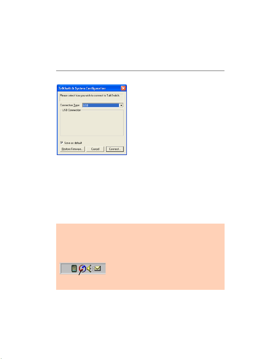
3. Double-click the TalkSwitch icon on your desktop to open the
configuration software. The dialog box in Figure 8 is displayed.
4. Select USB from the drop-down list and click Connect... A progress bar
indicates that the configuration is being retrieved. When this process is
completed, the TalkSwitch System Configuration window opens.
See Figure 30 on page 29
Figure 9: USB connection
1.7.3 Serial connection
Serial connectivity is an option if you do not have a
free USB port. The TalkSwitch package does not
include a Serial cable. The PC and TalkSwitch unit
must be in close proximity.
1. Connect the cable to the Serial port on your PC and to the Serial port on
the back of TalkSwitch.
Make sure that no other communication programs are running at the
same time as the configuration software.
Examples: Palm Pilot, Hot Sync, TalkWorks, Digital Camera, UPS Tracking
software, etc. These programs tend to occupy the COM ports, preventing
other programs from using them.
Look in your system tray for programs using your
COM ports. Rolling your mouse cursor over each
Hot Sync
icon will also indicate the name of the associated
program.
2. Press the Power button on the front of your TalkSwitch and turn on your
computer.
TALKSWITCH INSTALLATION 11
Page 24

3. Double-click the TalkSwitch icon on your desktop to open the
configuration software. The dialog box below is displayed.
Figure 10: Serial connection
4. From the drop-down list in the dialog box, select Serial as the connection
type.
5. Select a COM port (COM1 or COM2) from the Serial ports drop-down list
and click Connect... A progress bar indicates that the configuration is
being retrieved. When this process is completed, the TalkSwitch System
Configuration window opens. See Figure 30 on page 29.
1.7.4 Internet connection
Select USB from the drop-down list and click Connect... A progress bar
indicates that the configuration is being retrieved. When this process is
completed, the TalkSwitch System Configuration window opens.
See Figure 30 on page 29.
Ensure your unit is connected to a LAN with the supplied
Ethernet (CAT 5) cable. The top LED on the the back panel
beside the LAN port indicates that a connection has been
established with a switch or hub. To support remote
configuration over IP, map the TCP 9393 port from your firewall to
TalkSwitch. Please refer to the manual for your router/firewall to
activate port forwarding.
1. Double-click the TalkSwitch icon on your desktop to open the
configuration software. The dialog box below is displayed.
2. From the drop-down list in the dialog box, select Internet as the
connection type.
12 TA L K S W I TCH USER GUIDE • NORTH AMERICA
Page 25

Figure 11: Internet connection
3. In the Address field of the Internet IP Connection Settings section, enter
the public IP address or the FQDN of the TalkSwitch location and click
Connect.... A progress bar indicates that the configuration is being
retrieved. When this process is completed, the TalkSwitch system
configuration window opens. See Figure 30 on page 29.
You have the option to store several locations in the address book.
Figure 12: Address book
1. Click the Address Book button.
a) To add a new address, click New.
b) Type the name of the location into the Entry Name field.
c) Type the Internet address of the location into the Internet Address
field and click OK.
d) To edit or delete an existing entry, highlight the item you wish to
edit or delete and click Edit or Delete.
TALKSWITCH INSTALLATION 13
Page 26

1.7.5 File connection
You can load the latest configuration file saved on a PC to make edits and
save it again as a file or save it directly to TalkSwitch.
1. Double-click the TalkSwitch icon on your desktop to open the
configuration software. The dialog box below displays.
2. From the drop-down list next to Connection Type, select File.
Figure 13: File connection
3. Click the Browse button and select the configuration file you wish to
open and click Open.
Figure 14: Open TalkSwitch configuration file
4. Click Connect....
5. The TalkSwitch System Configuration window opens.
See Figure 30 on page 29.
When a unit is being configured, it is locked to prevent other computers
or persons using a phone from configuring changes at the same time. If
you leave the software open for longer than one hour, the unit unlocks
itself to allow configuration changes.
14 TA L K S W I TCH USER GUIDE • NORTH AMERICA
Page 27
Restore Firmware (button)
This button is available as an alternate method to update firmware if an
update attempt has failed. Click the Restore Firmware button, then select
which firmware file to load onto the unit. The firmware update will then
begin. Follow the instructions presented at each step. Progress will be
displayed as the update proceeds.
If you are downgrading to an earlier firmware version, and have more than
one networked TalkSwitch unit, you must perform the Restore Firmware one
unit at a time, with the unit separated from the network during the restore.
For more information, see 1.5.2 Upgrading the TalkSwitch software and
firmware on page 5.
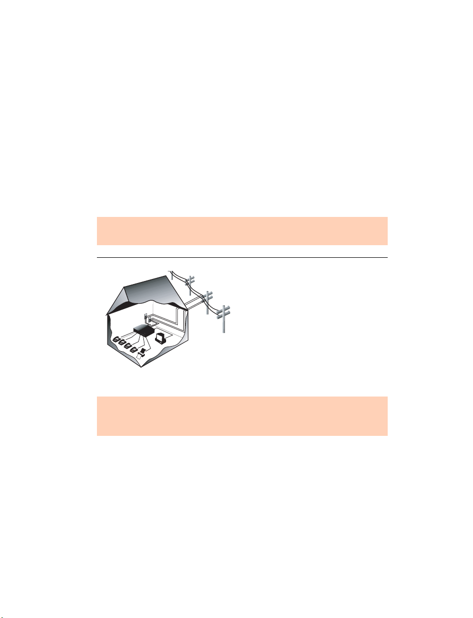
1.8 CONNECTING DEVICES
Move the unit(s) to a location where it can be attached to incoming
telephone lines and your telephone devices.
The computer connection is only needed to change the configuration
settings. It can remain disconnected at other times.
Figure 15: An example of residential wiring
TalkSwitch
Things to consider when placing your TalkSwitch
Recommendation: We recommend that you connect surge protectors
between the TalkSwitch unit(s) and your telephone lines to protect
against lightning damage.
Wiring
Make the most of your phone system with optimal home/office wiring. If
you need help wiring your house or small office and are not sure where all
the jacks are or what colors of wires to use, refer to Appendix H: Home/Office
Wiring Guide on page 213.
Location
Check the location of electrical wall outlets and telephone jacks in the room.
Place the unit(s) close enough to these items using your AC adapter and
telephone cords.
TALKSWITCH INSTALLATION 15
Page 28

1.8.1 Connecting incoming telephone lines
Advisory: In order to minimize disruption to your business, you may
want to configure TalkSwitch before connecting it to your telephone
lines and extension phones.
1. Choose a convenient wall jack to attach to your TalkSwitch and connect
your telephone lines.
2. Connect the TalkSwitch unit to the telephone company’s line sockets
using the dual-wire telephone cables provided. Take note of which
telephone line is connected to each line port. This information will be
used in the configuration section.
• Connect the first incoming phone line to L1.
• Connect the second incoming line to L2.
If you have a unit with more than two incoming lines, connect your
RJ-11 telephone lines, beginning with L1. If you have two lines out of
one phone jack, you will require a dual-to-two-single-line adapter or
replace the two-line cord with two single-line cords. Note that L3 and L4
do not exist on units with only two incoming line connectors.
All incoming calls will be routed to the extension phones by TalkSwitch.
Call handling includes call forwarding, transferring, voicemail, etc.
Incoming lines are not directly connected to any of the local extensions.
The software determines which incoming lines are routed to which local
extensions.
1.8.2 Connecting local extension telephones and other devices
Connect your single-line analog device to one of the unit extension jacks the
same way you would plug it into a standard telephone wall jack.
You can connect any regular analog extension telephone set, cordless
telephone or fax machine to the extension ports, E1-E4 (all unit models) and
E5-E8 (for unit models with more than four extension jacks).
1. Plug each internal telephone into extensions beginning with E1.
Connect a phone to E4 to ensure communication during a power failure.
2. If required, plug the fax line into E3 or E8.
16 TA L K S W I TCH USER GUIDE • NORTH AMERICA
Page 29
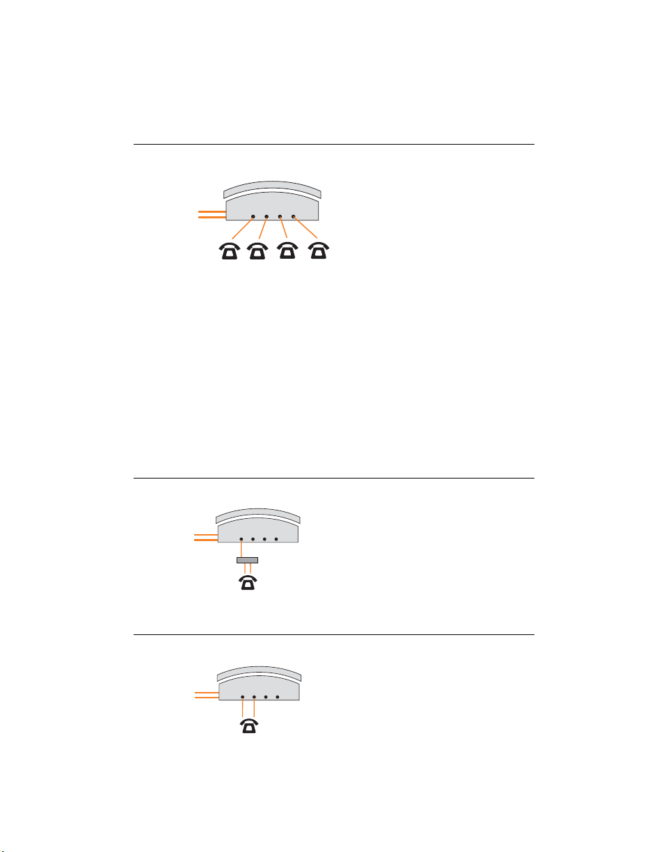
1.8.2.1 Connecting a regular single-line telephone
This is the basic, simple set-up. All functionality including transferring calls,
forwarding calls and voicemail, is handled by the unit. Even the most basic
of phones, once connected, will inherit these functions.
Figure 16: Single-line telephone
Each phone is connected to a single
extension. A call transferred to
extension 111 will ring the phone
connected on jack E1. A call
Incoming Phone Lines
TalkSwitch Jacks
E1 E2 E3 E4
transferred to extension 112 will ring
the phone on jack E2 and so on.
113
Extensions 111 112
114
1.8.2.2 Connecting a regular dual-line telephone
Most dual-line phones have separate plug-ins for two incoming telephone
lines (Line 1 and Line 2). If your dual-line telephone does not have separate
plug-ins, you can use a Line 1/Line 2 splitter to separate the two lines as
shown in Figures 17 and 18.
You can plug the dual-line phone into the TalkSwitch unit using one or two
extension jacks. Figure 17 below shows a dual-line phone using one jack.
Figure 18 on page 17 shows a dual-line telephone plugged into the unit
using two jacks.
Figure 17: Dual-line telephone on one jack
TalkSwitch extension 111 is connected
TalkSwitch Jacks
Incoming Phone Lines
E1 E2 E3 E4
Line Splitter
Extension 111
Figure 18: Dual-line telephone on two jacks
to a dual-line phone using one
extension jack. Calls on extension 111
show Line 1 as active.
TalkSwitch extensions 111 and 112 are
Incoming Phone Lines
TalkSwitch Jacks
E1 E2 E3 E4
connected to a dual-line phone using
two extension jacks. Calls on extension
111 show Line 1 as active. Calls on
Extensions 111 and 112
TALKSWITCH INSTALLATION 17
extension 112 show Line 2 as active.
Page 30
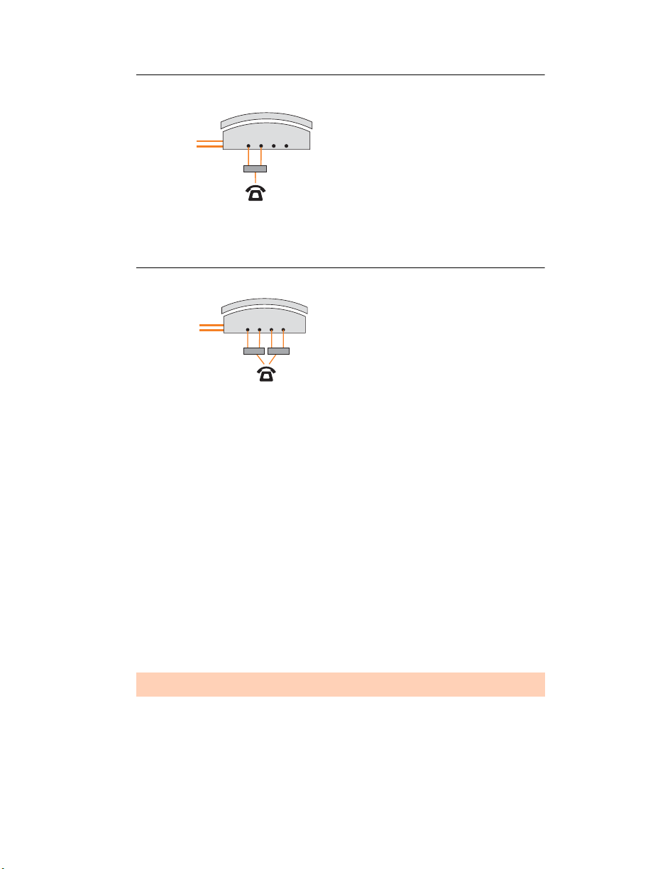
Figure 19: Dual-line telephone on splitter
r
TalkSwitch extensions 111 and 112 are
connected to a dual-line phone using a
line splitter. Calls on extension 111
Incoming Phone Lines
TalkSwitch Jacks
E1 E2 E3 E4
show Line 1 as active. Calls on
Line Splitter
Extensions 111 and 112
extension 112 show Line 2 as active.
1.8.2.3 Connecting regular multi-line phones
Figure 20: Four-line telephone
Jacks 111, 112, 113 and 114 are all
Incoming Phone Lines
TalkSwitch Jacks
E1 E2 E3 E4
Line Splitter Line Splitte
4-Line Phone
Extensions 111, 112, 113
&
wired to the four-line phone. When a
call is transferred to extension 111,
Line 1 on the phone shows as active.
Calls on extension 112 show Line 2 as
active and so on. You may configure
114
each incoming line to ring any given
number of extensions. Configure
incoming Line 1 to ring extension 111,
Line 2 to ring extension 112, etc.
1.8.2.4 Connecting an IP phone
Plug the IP phone into your switch/hub using the supplied RJ-45 cable.
Please refer to the IP Phone Configuration Guide in the TalkSwitch
documentation folder. If you are using a third-party IP phone, refer to the
user guide of the third-party IP phone for configuration instructions.
1.8.2.5 Attach an internal or an external modem
Plug the modem’s telephone cable into a unit extension jack. Your modem is
now an extension that can access all lines and take advantage of call routing
features.
Modems connected to a unit operate at a maximum of 28 kbps.
If you don’t want to change your dial-up settings for the modem, enable
Direct Line Access for the extension associated to the modem. For more
information, see 2.2.7 Local extensions on page 54.
18 TA L K S W I TCH USER GUIDE • NORTH AMERICA
Page 31

1.8.2.6 Connecting fax machines
If you are connecting a fax machine to a unit with two or four incoming
lines, plug it into local extension E3 or E8.
TalkSwitch provides you with three options to configure your fax machine.
Choose the best option for your office.
Option 1 — Dedicated Fax Line
You may already have an incoming dedicated fax line. You can leave this
line directly connected to your fax machine. Connect the remaining
incoming phone lines to your unit. Incoming phone lines will be handled by
the unit and your fax will work the way it has always worked.
Figure 21: Dedicated fax line
After installing TalkSwitch, the fax machine remains on its own dedicated line.
All incoming telephone lines are shared by the remaining office phones.
Advantages: It’s easy to set up and you don’t need to change the way your
fax handles calls.
Disadvantages: The dedicated fax line cannot be shared with the other
phone devices (i.e. you cannot make an outbound voice call on your fax
line). The dedicated fax line costs money, and may not be used as frequently
as it could be.
Option 2 — Distinctive Ring
Distinctive ring is a service provided by your phone company. A second
phone number is added to a phone line. A call to either phone number will
ring the same line with different ring patterns. You can use one ring pattern
to indicate a fax.
TALKSWITCH INSTALLATION 19
Page 32

Here’s how the TalkSwitch handles incoming calls:
Figure 22: Distinctive ring
After installing TalkSwitch, it automatically detects the distinctive ring pattern.
Faxes are automatically routed to the fax machine and calls to the phones.
Distinctive
RIng 1
Distinctive
RIng 2
Advantages: This option does not require a second physical line for faxes.
More telephone lines can be added as you grow. You can keep the same fax
arrangement.
Disadvantages: Your phone company may charge a fee for the distinctive
ring. If you choose this option, you will require the distinctive ring service
from your telephone company.
Option 3 — Automatic fax detection via the auto attendant
The auto attendant can detect incoming fax calls and route them
accordingly. To enable this, an auto attendant must answer all incoming
calls with your pre-recorded message. It will listen for a fax tone to
determine if the call is an incoming fax. If so, the call is routed to the fax
machine, otherwise the call follows your Call Handling settings. You must
create an auto attendant to use this method.
Figure 23: Automatic fax detection via auto attendant
All incoming calls are answered by the Auto Attendant.
The Auto Attendant then directs the call to the fax or local phone extensions.
Distinctive
RIng 1
Distinctive
RIng 2
Advantages: Calls are automatically handled for you. No distinctive ring
service and no listening to ring patterns is required. Incoming phone lines
are shared between all phones and faxes, making better use of your
resources.
Disadvantages: Some older fax machines do not emit a fax (CNG) tone.
Therefore, the auto attendant cannot detect incoming faxes from those
devices.
20 TA L K S W I TCH USER GUIDE • NORTH AMERICA
Page 33

If your auto attendant volume is set too high or if your telephone lines
are noisy, the auto attendant may have difficulty detecting the incoming
fax tone and therefore not route the call to the fax machine. You can
solve this problem by adjusting the volume. For more information, see
2.6.2 Audio Controls on page 107.
Options 2 and 3 require settings to be programmed into the unit using the
configuration software. For more information, see 2.2.6 Fax information on
page 49 and 2.4.2.4 Automatic fax detection on page 85.
1.8.3 Connecting devices to the music jack
The music jack is designed to support audio sources like a CD player, audio,
tape player or other sound devices for playing music or messages to callers
while they are on hold. Connect the audio source via its headphone output
to the music jack.
The music jack requires a 1/8" (3.5 mm) mono phono connector. If you have
more than one unit connected to a LAN, load a .wav file onto each unit to
eliminate the need for a separate music source for
each unit.
1.8.4 Connecting to the PA (public address) jack
The PA jack can be connected to a PA system for external paging or to an
amplification system to screen voicemail or to use as a line simulator. The
PA jack requires a 1/8" (3.5 mm) mono phono connector. If you have more
than one unit connected to a LAN, you need to provide a connection onto
the system to the PA system.
1.9 NETWORKING TALKSWITCH UNITS ON A LAN
Up to four 48-CA and/or 48-CVAunits can be networked together over a LAN
to increase the number of lines and extensions in your phone system.
1.9.1 Connecting TalkSwitch units to a LAN
You can plug your unit(s) into your existing LAN or operate it on its own
LAN with an Ethernet switch. Ensure that the firmware on all units is
updated before adding them to the LAN.
Check www.talkswitch.com/support/ for the latest updates.
TALKSWITCH INSTALLATION 21
Page 34

TalkSwitch unit enclosures are not designed for stacking. We recommend
wall-mounting units to maximize airflow and keep the units from
overheating.
1.9.1.1 Ethernet switch
A switch provides direct communication between units, thus keeping the
voice-over-LAN data isolated from other data on the network.
1. Connect up to four 48-CA and/or 48-CVA units to the LAN switch.
2. Connect a computer to the phone system using the LAN connection or
directly to the unit through the USB or Serial port.
3. Power up and configure your units before adding any IP phones that will
be part of the system. It is important that you place the IP phones on the
same subnet as TalkSwitch.
Example: If your TalkSwitch unit has the IP address 192.168.1.200, your IP
phone should use IP addresses in the range 192.168.1.xxx that do not
conflict with other IP addresses.
Figure 24: Three units connected via a switch
LAN
MUSIC PA
LAN
MUSIC PA
E5 E6 E7 E8
E1 E2 E3 E4
E5 E6 E7 E8
E1 E2 E3 E4
L4L3/L4
PF
L1/L2
L2 USB SERIAL POWER
L4L3/L4
PF
L1/L2
L2 USB SERIAL POWER
Reset
E5 E6 E7 E8
LAN
MUSIC PA
E1 E2 E3 E4
1Internet 234
POWER
L4L3/L4
PF
L1/L2
L2 USB SERIAL POWER
1.9.2 Power up all the TalkSwitch units
Connect the provided AC adapters to each unit and plug the adapters into
available power outlets. Turn the units on by pressing the Power button on
the front of each unit. The lights on the front panels of the units will flash.
This means that they are powered up and connected to the LAN, but their ID
numbers are not set.
22 TA L K S W I TCH USER GUIDE • NORTH AMERICA
Page 35

1.9.3 Setting or changing the unit ID
Units are shipped from the manufacturer with unit ID 1. If two or more units
are placed on the same LAN with the same unit ID number, it causes a
conflict. All the line lights on the front panel of the units are flashing. You
have to assign a different unit ID to each of the units.
To change the unit ID, the configuration software must be closed!
1. Pick up a telephone handset connected to one of the extension jacks on
the unit and press to enter command mode.
#
2. Enter a password if prompted.
3. Now, you have the following options:
Keys Result
00
01
02
03
04
#
#
#
#
#
Responds with the unit ID number of that particular unit.
Sets the unit ID to 1.
Sets the unit ID to 2.
Sets the unit ID to 3.
Sets the unit ID to 4.
The system indicates that the update was successful and the front panel
lights stop flashing after a few seconds. When the front panel Data light is
on solid, the units are ready for network use.
No IP information is required to configure TalkSwitch since it does not
use the TCP/IP protocol for voice traffic over the LAN. IP configuration is
required for remote management, voicemail to e-mail notification or for
VoIP.
1.9.4 How unit IDs affect system extension numbers
After successfully changing each unit ID to a unique number, it can be
identified by the network. More importantly, each local extension, remote
extension, and voice mailbox has a unique numbering system. The second
digit in the three digit identifier is the unit ID number, up to unit 4. See the
following diagram and table.
TALKSWITCH INSTALLATION 23
Page 36

Figure 25: Examples of three-digit identifiers
Unit ID 1 Unit ID 2 Unit ID 3 Unit ID 4
Local analog
111–118 121–128131–138141–148
or IP
extensions
Remote
210-219220-229230-239240-249
e x t e n s i o n s
Local
111-118121-128131-138141-148
m a i l b o x e s
Remote
210-219220-229230-23924
0-249
m a i l b o x e s
General
410-419420-429430-439440-449
m a i l b o x e s
1.9.5 Keep track of the lines and extensions
To keep track of the extensions and the lines connected to each unit, label
each unit with its unit ID. It simplifies matters when you need to add or
remove extensions and lines.
If the units are located in a room away from the extensions and you need to
identify the units, the View System Information utility in the configuration
software allows you to identify each unit as follows:
1. Open the TalkSwitch configuration software.
2. Click the View System Information link below the TalkSwitch image. See
Figure 26.
3. Select the Unit ID to verify.
4. Click the Identify button and observe the flashing LEDs. The lights stop
flashing when you click the Close button or when 5 minutes have
elapsed.
24 TA L K S W I TCH USER GUIDE • NORTH AMERICA
Page 37

Figure 26: System Information window
1.9.6 Optimizing the system for networked use
TalkSwitch units have been designed to operate optimally when in a
networked state. Below are a few items that have been designed for better
network use.
Configuration settings
All units are cloned with identical settings. If a unit has disappeared off the
network (adapter unplugged, LAN disconnected, LAN failure, etc.), the
system can still handle the calls since it retains the configuration settings of
the missing unit. If an extension or a voice mailbox cannot be reached, the
caller hears a system prompt: “The extension you are trying to reach is
currently unavailable, please try again later.”
Outgoing line hunt groups
When two or more units are on a LAN, the system tries placing calls out on
the same unit the call originates from. This avoids using a line across the
LAN on another unit, which helps to minimize the LAN traffic and optimizes
the opportunity for all inbound calls to connect across the LAN if required.
Auto attendants
There are a total of nine auto attendants that are shared by all units on the
LAN. When an auto attendant is recorded on any unit, it is automatically
copied to all other units on the LAN. This design minimizes LAN traffic and
provides functionality back-up in case a unit or units have disappeared off
the network (adapter unplugged, LAN disconnected, LAN failure, etc.). In
this event, all units can still answer inbound calls with the same auto
attendant messages.
Voicemail
All local extension and remote extension voicemail data is stored on the
unit where the extensions normally reside. For example, all greetings,
directory names and voicemail messages for extensions 121-128, 220-229
and mailboxes 420-429 are stored on the unit with unit ID 2. If a unit is
TALKSWITCH INSTALLATION 25
Page 38

completely filled with voicemail messages, new messages will not be stored
on other units. The system cannot accept anymore messages for mailboxes
belonging to that unit. If you need more memory, TalkSwitch memory cards
can be purchased from your reseller. To view the memory usage of each
TalkSwitch unit and each mailbox, click Tools -> Memory Usage ->
Voicemail or click Tools -> Voicemail Manager.
1.10 INSTALLING A MEMORY CARD
TalkSwitch memory cards are specifically formatted for use with TalkSwitch
units. They allow you to add additional voicemail message capacity to your
unit. Voicemail memory is used to store messages left in voice mailboxes. It
is also used to store auto attendant greetings and announcements.
TalkSwitch comes with 30 minutes built-in memory.
Figure 27: Memory card
Memory can be increased
in increments of 1 hour,
2 hours, 4.5 hours and 9 hours.
1. Insert the memory card into the memory slot with the gold contact face
down and the This side up tab showing. You don’t have to turn the unit
off or disconnect any of the telephones.
Figure 28: Memory card slot
26 TA L K S W I TCH USER GUIDE • NORTH AMERICA
Page 39

1.11 UPGRADING TALKSWITCH UNITS
As your business grows, your TalkSwitch unit(s) may need upgrading. You
have the option of upgrading your 24-CA unit to a 48-CA unit and your
48-CA unit to a VoIP model (48-CVA).
Figure 29: Top board and VoIP module upgrades for 24-CA to 48-CA
For customers upgrading the 24-CA unit to a
48-CA unit, we provide an upgrade kit. This
kit consists of a top board that you add to
your existing 24-CA unit, as well as a guide
containing detailed, step-by-step
instructions for the upgrade procedure.
For customers upgrading a 48-CA unit to a
48-CVA unit we provide a VoIP module that
they can add to their existing TalkSwitch
48-CA. We supply detailed, step-by-step
instructions on how to install the VoIP
module.
Customers upgrading the TalkSwitch 24-CA to a TalkSwitch 48-CA and then
upgrading to a TalkSwitch 48-CVA need a TalkSwitch top board and a VoIP
module. You can purchase upgrade boards and VoIP modules at your reseller.
1.12 WHAT THE FLASHING LIGHTS MEAN
Diagnostics for the lights flashing on the unit front panel
All line lights flashing simultaneously:
The unit ID of this unit is in conflict with another unit on the same LAN.
Make sure you assign a different unit ID to each unit. For more information,
see 1.9.3 Setting or changing the unit ID on page 23.
Line 2 and 3 lights flashing simultaneously:
This indicates a file system error. Terminate calls in progress. Reboot the
unit. Tools -> Reboot TalkSwitch or, on the front panel, turn the power
button off and back on. It will do a file system check and fix any problems.
Line 1 and 4 lights flashing simultaneously:
This indicates a voice mailbox error. Terminate calls in progress. Reboot
TalkSwitch. Tools -> Reboot TalkSwitch or, on the front panel, turn the
power button off and back on. It will do a file system check and fix any
problems.
TALKSWITCH INSTALLATION 27
Page 40

Line 1, 2, 3 and 4 lights flashing simultaneously:
The firmware needs to be updated or reloaded. Ensure that you update with
the last version, do not use the version on the installation CD. There might
be a newer version. Open the TalkSwitch configuration software.
File -> Update Firmware...
Line 1 and 4, then Line 2 and 3, lights flashing alternatively:
The system prompts are not loaded or corrupted. Reload the firmware. Open
the TalkSwitch configuration software.
File -> Update Firmware...
Line 1 and 3 lights, then Line 2 and 4 lights flashing repeatedly:
This is usually the case after a firmware update. Reboot TalkSwitch.
Tools -> Reboot TalkSwitch or, on the front panel, turn the power button
off and back on.
1.13 VERIFYING THE CONNECTIONS
If you are having problems, they could be due to loose cables. Check the
following:
1. Are your telephone cables connected to a wall jack at one end and the
unit at the other? Ensure the devices you are using as extensions
(phones, faxes, etc.) are plugged into the extension jacks located on the
back panel of the unit. Do not plug your extensions directly into a wall
jack unless that jack is wired to a unit extension jack.
2. Check the Serial, USB or LAN connection between TalkSwitch and
your PC.
3. Ensure that the unit AC adapter is plugged into a working power outlet
and that the unit is turned on. Make sure that you are using the
AC adapter supplied with your unit. This adapter cannot be substituted
with any other adapter. If your adapter appears to be defective, please
contact your TalkSwitch dealer to order the proper replacement.
4. If networked, ensure that you have the latest firmware loaded on all
units. To check the firmware version, open the configuration software,
and click the link View System Information. All units listed in the System
Information dialog box should have the same firmware version.
28 TA L K S W I TCH USER GUIDE • NORTH AMERICA
Page 41

CHAPTER 2
CHAPTER 2: TALKSWITCH CONFIGURATION
TALKSWITCH CONFIGURATION
2.1 SYSTEM CONFIGURATION
This chapter contains detailed information about all the features in the
TalkSwitch configuration software with step-by-step instructions on how to
customize these features to best suit your needs.
2.1.1 The configuration screen
The configuration screen consists of the following parts:
Figure 30: Initial configuration screen
X
Z
Y
[
TALKSWITCH CONFIGURATION 29
Page 42

The numbers in Figure 30 are explained below.
1. Menu items.
2. Configuration navigation controlling the display in the configuration
window.
3. Configuration window displaying configuration information.
4. View System Information is a link to the MAC address, IP address,
hardware and firmware version of the unit.
Context-sensitive help information is available for each option in the
configuration software. Rest your mouse cursor over any of the controls
and the information related to that control displays in a pop-up.
2.1.1.1 File Menu
Open... Opens the existing configuration files from the PC. TalkSwitch
backs up the configuration to a file called Configuration every
time you save the settings.
Save to
TalkSwitch
Save to File... Saves the current configuration to a file on your PC.
Exit Closes the configuration software.
Retrieve
Settings
Update
Firmware....
Saves the current configuration to the TalkSwitch unit.
Retrieves the settings from the unit connected to the PC.
Updates the firmware. For more information,
see 1.5.2 Upgrading the TalkSwitch software and firmware on
page 5.
2.1.1.2 View Menu
Toolbar Toggles the toolbar on/off
Status Bar Toggles the status bar on/off
30 TA L K S W I T C H USER GUIDE • NORTH AMERICA
Page 43

2.1.1.3 Tools Menu
Voicemail: Displays a dialog box showing internal memory
Memory
Usage
usage for voicemail messages.
Auto Attendant: Displays a dialog box showing internal
memory usage for auto attendant messages.
Voicemail
Manager
Terminal
Window
Call Logging
Output
Defaults... Resets the current page or the entire configuration to
Reboot
TalkSwitch
View Keys
Installed
Check for
updates
Displays a dialog box with options to check the voice mailbox
data, delete a mailbox password and reset mailboxes to
factory default.
Displays a command line interface. This option is useful for
troubleshooting in conjunction with technical support.
Real-time to Serial Port: TalkSwitch can output call detail
records to a PC connected to a Serial port.
Store to file on TalkSwitch: TalkSwitch can store call detail
records to a file stored on TalkSwitch. This file can be
retrieved/viewed from a web browser.
defaults.
Prompts you to save the configuration and provides options
when to reboot.
Lists your registration key(s) with the expiry date(s).
Checks the web site for configuration software updates.
2.1.1.4 Help Menu
About
TalkSwitch
Configuration
Utility...
User Guides... Opens the folder containing the TalkSwitch documentation.
Displays the TalkSwitch software version number, firmware
version and copyright information.
Support on
the Web...
TALKSWITCH CONFIGURATION 31
Launches your browser and links you to our support site.
Page 44

2.1.1.5 Configuration navigation
The configuration navigation organizes all the configuration topics within
folders. The following is a brief description of each folder seen in the
navigation section to the left of the window. See Figure 2.1.2 on page 33.
1. Open the TalkSwitch configuration software.
2. Click the sign beside each folder to expand it and display configuation
option sub-categories. When you configure TalkSwitch or when you wish
to modify the setup, it is helpful to be familiar with this structure.
About
TalkSwitch
System
Information
Voicemail Configure voice mailboxes and global settings for the
Call Handling Configure how to handle incoming calls. It includes auto
Call Back/
Call Bridge
Options Configure audio controls, troubleshooting and various
This link displays version information about the TalkSwitch
software. It also displays new voicemail messages, the time
and date and the current mode of operation.
Configure the system setup. From here you can activate lines
and extensions.
voicemail system.
attendant and individual call handling setups for all phone
numbers, extensions and modes of operation.
Configure the TalkSwitch call back/call bridge features in this
folder. Both of these features reduce your company’s
long- distance expenses.
operation settings in this folder.
32 TA L K S W I T C H USER GUIDE • NORTH AMERICA
Page 45

Figure 31: Configuration navigation
2.1.2 Special considerations when connecting multiple units to a LAN
Multiple units on a LAN will function as a single phone system. Some
features are expanded as you add units (e.g. number of voice mailboxes),
others are global in nature and are not expanded when you add more units
(e.g. park orbits).
To determine the number of local extensions and mailboxes your TalkSwitch
system supports, add the extension jacks (E1–E8) on all the units. In
addition, each unit supports ten remote extensions and mailboxes.
TALKSWITCH CONFIGURATION 33
Page 46

Example: If you have two 48-CA units connected on the same LAN, the
system can support 8 PSTN lines, 16 local extensions and 20 remote
extensions.Each unit is identified with a tab at the top of the configuration
window, System Information -> Telephone Lines to allow you to select
the unit in the group.
Figure 32: Unit tabs
The features described below are not affected by the number of units on
the LAN.
Feature Description
Auto Attendant
(See 2.4.2 Auto
attendant on page 80)
Music on Hold
(See 2.2.10 On-Hold/
Ringback on page 63)
Call Back
(See 2.5 Call Back/Call
Bridge on page 98)
Ring Groups
(See 2.2.9 Extension ring
groups on page 61)
Park Orbits There are 10 global park orbits (500-509). Any
There are 9 auto attendants shared by all units on
the LAN. This means that all inbound calls can be
answered by the same auto attendant on an
incoming line. When a new auto attendant is
recorded on a unit, it is automatically copied onto
all the other units.
There are two ways to add music on hold to your
system:
• through an external audio source
• by loading an internal music file
There are 4 auto call back accounts per unit. To use
an announced message for a particular auto call
back account, you need to record the announced
message on the same unit as the account. This
means calling in on a line that is physically
connected to the unit with the account, or using an
extension connected to the unit.
There are 10 global ring groups (300-309) regardless
of the number of units on a LAN. Each group is
capable of ringing any extensions on the network.
A combination of 32 analog and IP extensions can
be part of a ring group.
person can put a caller on hold in a temporary park
orbit so that the call can be retrieved from any
extension in the office.
34 TA L K S W I T C H USER GUIDE • NORTH AMERICA
Page 47

Public Address (PA) Each unit has a PA output for connection to a
public address system. The PA output for a
TalkSwitch unit is only accessible from extensions
connected to that unit. To connect all outputs to a
single amplifier, you will require an adapter.
2.2 SYSTEM INFORMATION
Some of the configuration screens that follow may vary depending on
whether the unit is networked or not. In most cases, the 48-CA/CVA
screen is shown unless the caption indicates a 24-CA screen. The 24-CA
models do not have IP Configuration and VoIP Configuration in the
System Information folder.
2.2.1 Administration
For security reasons, we recommend that you use password protection at the
administrator level. The password is entered at configuration start-up and
when you access the configuration through an extension phone.
To activate the use of a system password:
1. Click the next to System Information -> Administration.
Figure 33: Username and password
2. If you have units in different locations, we recommend that you assign a
system name to each unit for tracking purposes. Enter a name in the
System Name field. The system name will also be required when you are
logging in through the web interface of the unit for status or Call Detail
Record (CDR) information. For more information, see
Chapter 4: Call Detail Record (CDR) Logging on page 147.
TALKSWITCH CONFIGURATION 35
Page 48

3. Enter a system password in the System Password field. It has to be a
4- to 8-character numeric password, so that you can also enter it on a
touchtone phone.
Figure 34: Username and password for a VoIP enabled unit
Caution: If you leave the password field blank and you are connected to
the Internet using TCP port 9393 mapped to the unit, the system will be
vulnerable to configuration changes by anyone on the Internet!
To enter a new password:
1. Click in the System Password field.
2. Type a password and click OK.
To change the password:
1. Click in the System Password field.
2. Type a new password and click OK.
To delete a password:
1. Click in the System Password field.
2. Do not enter anything and click OK.
36 TA L K S W I T C H USER GUIDE • NORTH AMERICA
Page 49

Figure 35: Password dialog box
.
3. After entering, changing or deleting a password,
click File -> Save settings to TalkSwitch or click the middle icon in the
tool bar to save the settings.
Figure 36: Save settings
New settings must be saved to the
TalkSwitch phone system to take effect.
A progress bar will show the data
exchange to the TalkSwitch unit.
It takes only a few seconds to
complete.
2.2.2 IP Configuration
TalkSwitch 48-CVA requires an IP address to function properly. If you have a
TalkSwitch 48-CA, an IP address is required if you want to configure the
system remotely or if you want to network it with a CVA on a LAN. There are
two methods of configuring the IP settings, automatic and manual. The
automatic setting is the default. See Figure 37..System IP Settings section
The Obtain IP and DNS information automatically radio option is selected by
default. This selection refers to DHCP (Dynamic Host Configuration
Protocol). If you are on a DHCP server, the IP and DNS information will be
filled in automatically.
1. Click the next to System Information -> IP Configuration.
TALKSWITCH CONFIGURATION 37
Page 50

Figure 37: Automatic IP configuration
Additional VoIP configuration information is contained throughout this
guide. For more information, see 5.4 VoIP Configuration on page 162.
2. To configure the IP information manually, select Use the following IP and
DNS information.
Figure 38: Manual IP configuration
If you do not have a DHCP server, the following fields need to be completed
if you plan on using the VoIP capabilities of TalkSwitch 48-CVA.
38 TA L K S W I T C H USER GUIDE • NORTH AMERICA
Page 51

Unit IP Address:
Assign an available static IP address to each unit (1-4). If you use a DHCP
server, you have to reserve an IP address for each unit. To reserve an IP
address, you need the MAC address of each unit. To view the unit MAC
address, click the View System Information link on the About TalkSwitch
configuration page. For more information, see 2.1.1 The configuration
screen on page 29.
Subnet Mask:
Enter the subnet mask for the LAN. This address determines what subnet
the specific addresses belong to.
Default Gateway:
Enter the IP address of the gateway on your network. A gateway is a
hardware device (i. e. router/NAT) that connects the office network to
the Internet. The gateway allows you to share a DSL, cable modem or
other Internet connections with all of the computers and IP devices in
your office network.
Preferred DNS Server:
Enter the IP address of the preferred/primary DNS server. DNS is a service
that is used to resolve a domain name to an IP address.
Example: A DNS server is used by your web browser to resolve
www.talkswitch.com to an IP address such as 64.26.166.52. For more
information, see Chapter 5: VoIP Information on page 155.
Alternate DNS Server:
Enter the alternate/secondary DNS servers IP address if applicable.
Public WAN IP Address
Type of public WAN IP address for Internet Connection:
This field is set to dynamic by default. The unit checks the public IP address
every 5 minutes. If it changes, it automatically updates to the correct
information in order to manage VoIP calls properly.
The dynamic setting will not work in closed network environments. In a
closed network environment, change the field to static and enter the
appropriate IP address. If the unit is not behind a router, enter the IP address
of the unit acting as the local proxy.
Current public WAN IP address:
For the dynamic setting, this entry shows the current public IP address and
is not editable. For the static setting, enter the IP address or the FQDN of
your location.
TALKSWITCH CONFIGURATION 39
Page 52

Public WAN IP address-checker server name:
For the public IP address type dynamic, this entry shows the current server
name for the IP checker utility. If the public IP address type is static, no
information is required.
The default location is checkip.talkswitch.com. An IP checker application is
running on the server that responds to requests from units for the public IP
address at its location.
Fully Qualified Domain Name:
A Fully Qualified Domain Name (FQDN) is required if this location acts as the
SIP server and does not have a static public IP address from your service
provider. You can obtain FQDNs for free at www.dyndns.org. If your router
supports DDNS, program the required information to update the DNS servers.
If not, download one of the applications specified on the site. It needs to
run on a PC connected to the same LAN to update the DNS servers. If the
unit is enabled as a SIP server and no FQDN was entered, the prompt below
displays.
Figure 39: Fully Qualified Domain Name (FQDN)
2.2.3 Telephone Lines
This section tells TalkSwitch about the telephone lines plugged into its back
panel. Select a line and fill in the information. For each line there is a status
message: Line Detected, indicating that TalkSwitch detected a line plugged
into the associated line port. If a line is plugged into a line port and is not
detected, check your telephone line connection.
1. Open the configuration software, if not already open.
2. Click System Information -> Telephone Lines.
40 TA L K S W I T C H USER GUIDE • NORTH AMERICA
Page 53

Figure 40: Telephone lines
In the Phone numbers section
Enter the main telephone number for the line connected to TalkSwitch.
Enable the Distinctive Ring 1 and/or Distinctive Ring 2 if you have this
service on the current line and wish to have incoming calls handled
differently on the basis of the distinctive ring. If you want distinctive ring
numbers handled the same way as your Main number, do not place a
checkmark in the box.
If you checked the box, enter the distinctive ring telephone number for
each of the distinctive ring numbers associated with this line.
• Distinctive Ring 1 corresponds to any double ring pattern.
• Distinctive Ring 2 corresponds to any triple ring pattern.
3. Click the Activate line checkbox to enable the telephone line port.
4. Enter the normal telephone number for the telephone line as the
Main number.
In the Telephone Company Services section
Check the boxes that correspond to telephone company services that are on
this line. Descriptions of these services and how your unit deals with them
are provided below. For more information, see Appendix B: TalkSwitch and
Telephone Company Calling Services on page 193.
3-Way Calling/Conference
TalkSwitch can work with a service to forward calls to remote extensions or
other external phone numbers while using same line connect. You can use
TALKSWITCH CONFIGURATION 41
Page 54

this service as an option for bridging calls to external numbers when you
call into a unit from outside. If you are having difficulties with line volume
levels when you forward calls to remote extensions or when you are using
call bridge, forward calls using 3-way calling.
Transfer and Clear (Centrex/Plexar transfer)
TalkSwitch can clear the line after forwarding a call to a remote extension, if
your telephone line supports this feature. If you enable this feature without
having the service, callers are disconnected when a unit attempts to forward
their call to the remote extension.
Call Waiting
Check this box if you have a call waiting service on the current line. Note
that you should remove this service from your line, since there is no way for
the unit to answer a second call on the same line while it is handling the
first call. You may want to consider adding the hunt/rollover service to your
lines instead.
Caller ID
Check this box if the current line provides Caller ID information. The unit
passes the Caller ID information along to the selected extension. Also,
TalkSwitch can use the time information provided by Caller ID to update the
TalkSwitch clock.
Telephone Company Voicemail
Check this box if you are subscribed to a telephone company voicemail
service.
Hunt/Rollover/Busy Forwarding
Check this box if the current line is associated with a line hunt or Line
Rollover service from the telephone company. Any lines that belong to a
hunt/rollover group should be configured to handle calls the same way.
Calibrate Lines (button):
Click this button whenever a line is added or changed. Calibrate Lines allows
TalkSwitch to optimize lines for call bridge and call forwarding. Only lines
that are detected get calibrated.
For information about configuring the VoIP numbers, see
5.4.3 VoIP Numbers on page 170.
2.2.4 Line hunt groups
There are a total of 9 line hunt groups that control outbound call line
selections. These line hunt groups are used by local and remote extensions,
42 TA L K S W I T C H USER GUIDE • NORTH AMERICA
Page 55

and by call bridge. Each hunt group can support several line choices and
attempt to use an available line in the order that they are listed for that
hunt group. These settings have no effect on incoming calls.
Default setup:
Hunt Group 9: selects any available telephone line.
Hunt Group 81: selects telephone Line 1.
Hunt Group 82: selects telephone Line 2.
Hunt Group 83: selects telephone Line 3 (only four-line models).
Hunt Group 84: selects telephone Line 4 (only four-line models).
Hunt Group 88: selects any available VoIP number (only applies
1. Select System Information -> Line Hunt Groups.
2. Select a Line Hunt Group and enter a unique Line Hunt Group name to
identify this group elsewhere in the configuration software.
3. Under Set Line Hunt Group, select the Line Type. If you wish to use this
hunt group to access telephone lines, select Phone Lines. To use this hunt
group to access VoIP numbers, select VoI P numb ers.
4. Click the checkbox(es) next to the line(s) you wish to add to the hunt
group.
Figure 41: Hunt group configuration
when a VoIP unit is present on the LAN).
If multiple units are connected to the LAN, outbound calls always hunt
the lines on the unit where the extension is connected. This minimizes
network traffic between units.
TALKSWITCH CONFIGURATION 43
Page 56

Figure 42: Hunt lines on same unit first
2.2.5 Automatic Route Selection and Toll Restriction
What is Automatic Route Selection (ARS)?
ARS allows you to automatically direct outgoing calls to selected lines. With
ARS, you can ensure that your outgoing long-distance calls use the line with
the lowest-cost long-distance plan or that your inter-branch calls always use
your VoIP trunks.
What is Toll Restriction?
Toll restriction blocks calls to specific destinations. With toll restriction, you
can prevent extensions in your system from placing unauthorized longdistance calls.
Example: You have a low-cost long-distance plan. You assign one telephone
line to handle all local calls and another line for long-distance calls within
North America to go through your long-distance plan. At the same time, you
can block unauthorized long-distance calls from going overseas.
TalkSwitch uses the first several digits (referred to as ‘leading digits’) of a
phone number to automatically select the specific phone line that you have
chosen to make that type of call. ARS and toll restriction use line hunt
groups, which have to be configured to provide access to telephone lines or
VoIP trunks.
Planning Automatic Route Selection and Toll Restriction
• Identify the leading digits of the numbers for the calls to be routed or
blocked.
• Identify the carrier codes.
44 TA L K S W I T C H USER GUIDE • NORTH AMERICA
Page 57

• Identify which telephone lines and VoIP trunks are connected to
different networks and services.
• Identify which extension’s calls you wish to route or block.
Ensure that the line hunt groups are configured before using ARS. For
more information, see 2.2.4 Line hunt groups on page 42.
Entering leading digits and assigning actions
What are leading digits?
• Leading digits are the first digit or first several digits of an international
access code, country code, area code or phone number.
• Leading digits can be anywhere from 1–11 characters.
• Leading digits can include numeric characters 0–9 and .
The leading digit for long-distance calls within North America is 1. As soon
as you dial 1xxx xxx-xxxx, the system recognizes that you are making a
long-distance call within North America.
To place an overseas call from North America, you would dial 011, followed
by the country code, the area code and the phone number (i.e. 011 xx xx
xxx-xxxx). Once you dial 011, the system recognizes that the caller is
placing an overseas call (011 are the leading digits).
ARS will route or block calls according to the leading digits you define and
the actions you chose in the TalkSwitch Configuration under System
Information -> Auto Route Selection.
*
Figure 43: ARS — leading digits
TALKSWITCH CONFIGURATION 45
Page 58

1. Enter the leading digits you wish to route or block in the Leading Digits
field.
2. Select the desired Action (route to a specified line hunt group or block
calls) from the corresponding drop-down list.
The entries that you specify for ARS match the dialed digits with the
longest leading digits entry. If the numbers dialed match the digits that
you specified, the call is routed to a line hunt group or blocked according
to the Action you selected.
Entering carrier codes and start times
What is a carrier code?
In addition to leading digits, you can access your long-distance plan. It may
be different for North America and for overseas as well as during different
times of the day (i.e. business hours or after hours). The Carrier Code 1 and
Carrier Code 2 columns give you theses options. TalkSwitch automatically
adds a 2-second pause after dialing the carrier code to pick up the dialtone
of the long-distance provider. A carrier code can be up to 24 digits long,
including ‘*’, comma ‘,’ and ’w’. The comma causes a 2-second pause; ‘w’
waits for the dial tone.
3. Enter the telephone number for your long-distance plan. Enter the
number without spaces or dashes.
4. Select Start Time 1 for Carrier Code 1 from the drop-down list. If the
access number is the same 24 hours a day, click the checkbox next to All
Day. If you have a different plan for business and after hours, enter it in
the Carrier Code 2 field and select a time for Start Time 2.
Figure 44: Examples of leading digits
• If you dial 9 followed by a phone number that does not start with 1, 01
or 01161, you access an outside line. The number is automatically routed
according to the configuration of line hunt group 9.
46 TA L K S W I T C H USER GUIDE • NORTH AMERICA
Page 59

• If you dial 9 followed by 1, a 3-digit area code and a 7-digit number, you
access a line for long-distance calls in North America, as defined in line
hunt group 82.
• If you dial 9 followed by 01, the call is blocked. At the extension, you
hear a prompt stating “You are not permitted to dial this number” and
then a normal dial tone.
• If you dial 9 followed by 01161, an area code and a phone number, you
access a line for calls to Australia, as defined in line hunt group 83.
Figure 45: ARS and line hunt groups
Line hunt group 80
is used for Same
Line Connect. If
line hunt group 80
is enabled, it will
be subject to ARS
blocking rules.
Set local extension hunt group access
By default, all line hunt groups for each local extension are enabled. If you
wish to restrict access to some line hunt groups, you need to disable the line
hunt groups at the local extension.
1. Open the TalkSwitch configuration software.
2. Select System Information -> Local Extensions.
3. Click the Hunt Group Access button.
4. Remove the checkmark (by clicking it) next to the line hunt groups you
do not want to allow for that local extension.
Repeat these steps for all your local extensions. When you allow access to
line hunt groups that have ARS activated, the calls are routed through ARS.
Direct Line Access
If you enable Direct Line Access on an extension, calls placed from that
local extension are routed to the designated line hunt group. If ARS is
enabled on that line hunt group, the calls are routed through ARS.
TALKSWITCH CONFIGURATION 47
Page 60

Figure 46: Outgoing call options
Emergency Service Numbers section
The 911 emergency access number is always allowed through ARS, even if
the line is blocked.
Password Protection
We recommend that the administrator password protection be enabled when
you use automatic route selection and toll restriction. Enable the password
protection in the TalkSwitch configuration software under System
Information -> Administration.
Enter a 4- to 8-digit numeric password.
Telephone Line 3-Way Calling Services
Calls on telephone lines with the telephone company‘s 3-way calling service
are not routed through ARS. They are either allowed or blocked.
Call Detail Record (CDR) Logging
For information on CDR, please refer to Chapter 4: Call Detail Record (CDR)
Logging on page 147.
48 TA L K S W I T C H USER GUIDE • NORTH AMERICA
Page 61

Automatic Route Selection Examples
Blocking international calls, with exceptions
Leading Digits Action Objective
01
1
1212
Block Calls
Block Calls
Hunt Group 1
International calls are restricted.
Calls in North America are restricted.
Allow calls to New York area code 212
using Line Hunt Group 1.
10
Block Calls
Using alternative long distance provider.
Restrict access to premium services
Leading Digits Action Objective
1900
1976
900
976
Block Calls
Block Calls
Block Calls
Block Calls
Restrict access to premium inbound calling
services.
2.2.6 Fax information
TalkSwitch provides you with different options to configure your office for
fax calls. The advantages and disadvantages of each option are described
below, so that you can choose the best solution for your office.
Dedicated fax line
You may already have an incoming dedicated fax line. For more information,
see 2.2.6.1 Dedicated fax line on page 50.
Advantages: It is easy to set up and you don’t need to change the way your
fax handles calls.
Disadvantages: The dedicated fax line cannot be shared with the other
phone devices (i.e. You cannot make an outbound voice call on your fax
line). The dedicated fax line costs money and may not often be used.
Distinctive Ring fax detection
Distinctive ring is a service provided by your phone company. A second
phone number is added to the same physical telephone line. For more
information, see 2.2.6.2 Distinctive ring fax detection on page 52.
Advantages: It does not require a second physical line for faxes. More
telephone lines can be added as you grow and you can keep the same fax
arrangement.
TALKSWITCH CONFIGURATION 49
Page 62

Disadvantages: You only have one line and can only handle one call at a
time. The phone company may charge a fee for a distinctive ring.
Automatic fax detection with the auto attendant
An auto attendant can detect incoming fax calls and route them
accordingly. For more information, see 2.2.6.3 Automatic fax detection on
page 53.
Advantages: Calls are automatically handled for you, no distinctive ring
service and no listening to ring patterns are required. Incoming phone lines
are shared between all phones and faxes, making better use of your
resources.
Disadvantages: Older fax machines do not emit a CNG tone and the auto
attendant cannot detect them.
2.2.6.1 Dedicated fax line
If you have a dedicated fax line or number, your fax machine should be
connected to an extension jack on the same unit as the fax line. Leave this
line directly connected to your fax machine. Connect the remaining
incoming telephone lines to your unit. Incoming telephone lines will be
handled by the unit and your fax will work the way it has always worked.
Figure 47: Dedicated fax line
After installing TalkSwitch, the fax machine remains on its own dedicated line.
All incoming telephone lines are shared by the remaining office phones.
1. Open the TalkSwitch configuration software.
2. Select System Information -> Fax Information.
3. In the Dedicated fax line section, select the fax number from the
drop-down list next to Fax number:.
4. In the Fax extension section, select the extension number where your
fax is connected.
50 TA L K S W I T C H USER GUIDE • NORTH AMERICA
Page 63

5. Save settings to TalkSwitch.
Example: If your fax machine is connected to E8 on the rear of unit 1, select
extension number 118 for units with 8 extension jacks or 113 for units with
4 extension jacks. If your fax machine is connected to E8 on a unit with Unit
ID 2, the fax extension number is 128.
Figure 48: Fax information
If you do not see your fax number in the list, make sure you have activated
the line in the TalkSwitch configuration software under
System Information -> Telephone Lines.
Figure 49: Telephone lines
TALKSWITCH CONFIGURATION 51
Page 64

By default, when a dedicated line and a fax extension have been selected
for the first time, the software automatically configures the incoming call
handling properties for that line to ring only the fax extension that you
have specified.
2.2.6.2 Distinctive ring fax detection
A single telephone line can have two assigned numbers with a different ring
pattern for each number. Based on the ring pattern, you pick up the phone
or let the fax answer the call.
Figure 50: Distinctive ring without TalkSwitch
Distinctive
RIng 1
Figure 51: Distinctive ring with TalkSwitch
After installing TalkSwitch, it automatically detects the distinctive ring pattern.
Faxes are automatically routed to the fax machine and calls to the phones.
Distinctive
RIng 1
Distinctive
RIng 2
Distinctive
RIng 2
Here is how TalkSwitch handles incoming calls:
The unit automatically routes faxes to the fax machine and calls to the
telephone.
One of the incoming lines will have a distinctive ring number assigned to it.
The unit recognizes this number as an incoming fax line. Follow the steps
below:
1. Open the TalkSwitch configuration software.
2. Select System Information -> Telephone Lines.
3. Choose the line number for the incoming fax and click in the box next to
Activate line.
52 TA L K S W I T C H USER GUIDE • NORTH AMERICA
Page 65

4. In the Phone numbers section beside Main number, enter the telephone
number that people dial to call your office.
Figure 52: Telephone lines
5. Click the checkbox beside Distinctive Ring 1:
6. Enter the distinctive ring number in the text field. This is the number
people will call to get your fax machine.
7. Click Fax Information.
8. In the Dedicated fax line section, select the fax number from the
drop-down list next to Fax number:
9. In the Fax extension section, select the extension number where your fax
is connected.
10. Save settings to the unit.
2.2.6.3 Automatic fax detection
Provided all calls are answered by the auto attendant, it can detect
incoming fax calls and will route calls to their destination.
If an auto attendant is already configured, do the following:
1. Open the TalkSwitch configuration software if not already open.
2. Select Call Handling -> Auto Attendant.
3. Select Auto Attendant 1. You can configure additional auto attendants
later.
TALKSWITCH CONFIGURATION 53
Page 66

4. In the drop-down menu next to If a fax call is detected:, select go to local
extension and select 118 (113 for units with 4 extension jacks).
Figure 53: Fax routing
5. Save settings to the unit.
Set up at least one auto attendant to answer all incoming calls, play a
recorded message, allow callers to dial their party’s extension or dial 0 for a
receptionist. For more information, see 2.4.2.1 Adding/configuring an auto
attendant on page 80.
2.2.7 Local extensions
Local extensions can be analog phones connected to any of the extension
jacks at the back of TalkSwitch or IP phones on the same subnet registered
with your TalkSwitch system. For more details on connectivity, see
1.8 Connecting devices on page 15. Local extensions are activated with the
associated voice mailbox by default. Voice mailboxes for each local
extension can be de-activated in the Voicemail folder.
Activating a local extension for use with an analog (regular) phone
By default, all analog extension ports are active. Plug phones into the
extension ports and you are ready to make and receive calls.
Figure 54: Analog extension
54 TA L K S W I T C H USER GUIDE • NORTH AMERICA
Page 67

Configuring a local extension for use with a IP phone
1. Open the configuration software.
2. Select System Information -> Local Extensions.
3. Change the radio button from Regular Extension to IP Extension.
4. The default Username and Password are <user ext#> and <pass ext#>.
Change either as required.
Figure 55: IP extension
Please refer to the configuration guide for your IP phone in the
TalkSwitch documentation folder. If you are using a third-party IP phone,
refer to the user guide for that phone.
Once the phone has been programmed with the extension number,
username, password, registrar and proxy information you can confirm
registration as follows:
1. Connect the IP phone to the LAN with the Ethernet cable.
2. Connect the power to the IP phone.
3. Click the Refresh button when the phone indicates that it is registered.
Additional fields
Caller ID Information section
Last name/First name:
Enter the last and first name of the person associated with the extension. If
you want to include the person in the dial-by-name directory used by the
auto attendant, you must enter the last name. The name entered displays on
the Caller ID of other local extensions. The person using that extension is
required to record her/his name for the directory.
TALKSWITCH CONFIGURATION 55
Page 68

If a name was not recorded before you set up the associated voice
mailbox, pick up the handset, press + <mailbox number>
and press 4.
For VoIP calls, use: [this number]
Select the number you want to display at the remote location when VoIP
calls are placed from this extension. If Default VoIP number is selected, the
phone number associated with the outgoing VoIP port is used. This selection
makes the most sense if your VoIP numbers have been configured to handle
all inbound calls the same way.
For <Service Provider> VoIP calls, use:
Figure 56: IP extension username and password
* *
Phone Type
If you have a TalkSwitch phone connected to this extension, select the
model of phone. TalkSwitch sets have some integrated features that will not
work unless the proper phone is specified. Features include intercom paging,
group paging over the speaker, and message waiting counter on the TS-80,
TS-200, TS-400 and TS-600 phones.
For the IP extensions, TalkSwitch requires IP phones that have G.711 CODEC
support.
The IP phones officially supported by TalkSwitch are:
• Polycom Series — 301, 430, 501, 601 (minor support differences
between models)
• Grandstream — GXP-2000 (Excellent low budget phone)
• Counterpath — Eyebeam soft client.
56 TA L K S W I T C H USER GUIDE • NORTH AMERICA
Page 69

When Polycom or Grandstream is selected, the username and password
are fixed and not editable.
Other phones may work with the system, but not all the features may be
supported. We strongly recommend that you only use the IP phones
supported by TalkSwitch.
Figure 57: Phone types
Direct Line Access... (button)
This feature allows users to access an outbound line without dialing extra
digits. When the extension goes off-hook or a number is dialed on a IP
phone without first dialing a hunt group, Direct Line Access allows you to
configure the extension to access a specific hunt group automatically for
outbound calls.
Example: You may have a fax machine connected to this extension and
don‘t want to reprogram the speed dial numbers. Click Direct Line Access
and choose the hunt group. As soon as the fax goes off-hook, the unit finds
an available line.
Warning: When using Direct Line Access with an analog phone, you hear
the telephone company dial tone when you pick up the handset. The
following features are only available from the TalkSwitch internal dial
tone:
• Intercom calling
• Hold and retrieve
• Line hunt groups
• Voicemail retrieval/access
• Call pick-up
• P.A. access,
• Parked call retrieval
• Do Not Disturb functions
• Entering command mode
To obtain an internal dial tone at an extension which has Direct Line
Access enabled, dial Flash after going off-hook on an analog set. On a IP
phone, dial , then press Dial, Send or .
TALKSWITCH CONFIGURATION 57
* *
#
Page 70

Hunt Group Access... (button)
You can permit or restrict specific hunt group access to the extension. Click
the checkbox next to the Line hunt groups that you want to allow for this
extension
.
2.2.8 Remote extensions
A remote extension allows you to connect an external telephone number.
This could be a cell phone or a number to your office. You can have it
operate similar to a local extension in your office. Any external telephone
number can be configured as a remote extension (i.e. cell phone, PDA, home
telephone or branch office).
With remote extensions, you can have calls forwarded directly from your
office to any phone number you choose. You can choose to screen callers. If
the remote extension is busy or unanswered, calls can be transferred back to
your office voicemail, another extension or forwarded to another out-ofoffice telephone number (e.g. to a business partner’s cell phone).
To set up remote extensions, see Figure 58 and follow the steps below.
1. Open the TalkSwitch configuration software.
2. Select System Information -> Remote Extensions.
3. Click on a remote extension number, starting with 210. Add more
numbers as needed.
If a TalkSwitch has Unit ID 2, the remote extension numbers are 220–229.
Unit ID 3 has remote extensions 230-239 and Unit ID 4 240-249.
4. Click in the checkbox next to Activate Extension <ext>.
5. Enter a last and a first name into the Last name: and First name: fields to
identify the extension.
6. Enter the external phone number.
Enter the number the same way you are dialing it from a regular phone.
You may use digits 0–9, space, comma, dash, and .
A comma creates a two-second pause in the dialing string.
7. In the drop-down list next to Connect using:, we recommend that you
leave it at Hunt Group 9 unless you have pre-configured another group.
58 TA L K S W I T C H USER GUIDE • NORTH AMERICA
#
*
Page 71

8. If you have a 3-Way Calling or Transfer and Clear service from the phone
company, click the checkbox next to Use Same Line Connect.
9. Save settings to the unit.
Figure 58: Remote extensions
Once your remote extensions are configured, calls can be forwarded by the
auto attendant or transferred by someone in your office. There are 10
remote extensions available per TalkSwitch unit.
Use Same Line Connect
Check this box to allow incoming calls to use the same line when
forwarding it to the remote extension. This feature allows only one line
to be used when forwarding incoming calls to a remote extension. It can
only be used when the line of the originating incoming call has 3-Way
Calling/Conference or Transfer service (Centrex/Plexar). If the line does
not have any of these services, the call will be forwarded using the hunt
group chosen in the Connect using: drop-down list.
If you have a Transfer and Clear service on your line(s) and want to have
TalkSwitch clear lines after forwarding calls to remote extensions, you
need to enable Clear telephone line after call transferred (Options ->
Transfer Options). If your service requires the remote extension to
answer the call before the transfer can be made, use one of the screening
TALKSWITCH CONFIGURATION 59
Page 72

options in Call Handling -> Remote Extensions in the drop-down list
under the Answered tab.
Remote extensions do not have the ability to transfer calls manually
when using Same Line Connect.
When using Same Line Connect, callers hear silence while they are on
hold. The callers are on hold at the telephone company and not at
TalkSwitch. If you want callers to hear music while they are on hold for
calls forwarded to remote extensions, don’t use Same Line Connect. It is
best to experiment with different settings in order to decide what works
best for your configuration.
Forwarding calls to a remote extension
• Manually from a local extension:
Analog phone: Press Flash and the remote extension number (e.g. 211).
IP phone: Press Transfer and the remote extension number followed by
Dial, Send or . For more details, see Appendix I: Functions and
commands for IP phones.
• From an auto attendant:
The auto attendant can be configured to route the calls to your remote
extension. The auto attendant might say: “To reach Mr. A’s cell phone,
press 1, to reach his office, press 2 or press 0 to reach a receptionist.” You
can also instruct callers to dial the extension directly at the auto
attendant. You could use this auto attendant as a company greeting or
within your call cascade sequence at your local extension. For details,
refer to 2.4.2 Auto attendant on page 80.
•From a call cascade:
A call cascade sequence can route a call to a remote extension.
If there is no answer at your desk, the call is transferred to your cell
phone. If you don‘t answer your cell phone, the call is forwarded to your
office voicemail. The caller hears music on hold. For details, refer to
2.4.5.1 Local extensions on page 90.
#
Transferring calls from a remote extension
1. Press
group, or press again and a mailbox number to transfer the call to
voicemail.
60 TA L K S W I T C H USER GUIDE • NORTH AMERICA
and dial any local extension, remote extension, or ring
* *
*
Page 73

Figure 59: Remote extensions
2.2.9 Extension ring groups
An extension ring group is a group of local extensions that ring in unison.
TalkSwitch supports 10 ring groups with numbers 300 to 309. They are
accessible from local extensions and through the auto attendant. By default,
extension 300 is configured to ring all extensions.
A phone system with 4 units can support a combination of 32 analog and
IP extensions with a maximum of 20 IP extensions.
Ring groups features
• independent call cascade
• distinctive ring cadence
• call screening capabilities
Setting up extension ring groups
1. Open the TalkSwitch configuration software.
2. Select System Information -> Extension Ring Groups.
3. Choose an Extension Ring Group number, starting with 300.
4. Click in the checkbox next to Activate Ring Group 300.
5. Enter a name in the field next to Ring Group Name:.
TALKSWITCH CONFIGURATION 61
Page 74

6. In the Set Ring Group window, choose the local extensions you want to
ring in unison.
7. Select a Ring pattern: from the drop-down list to identify the incoming
call before you pick up the phone.
8. Save settings to TalkSwitch.
Figure 60: Ring groups
Different uses for extension ring groups
You can send calls to specific groups of employees.
Example: If you have a company with several departments, you can
configure extension ring group 300 for the sales department to ring
extensions 111, 112, 113, and 114. Ring group 301 might be for technical
support, ringing extensions 115 and 116.
Identify types of calls by different ring patterns
Example: You are the president of a company and you don‘t want to handle
calls from the general public, yet you want to be alerted when important
colleagues try to contact you. Your regular local extension may be 111 for
most people, but you can configure an extension ring group 305 to ring your
extension with a different ring pattern. You tell your colleagues to choose
extension 305 at the auto attendant or ask to be transferred to extension
305 when speaking to someone in the office. You can tell by the ring
pattern if the call is to 305 or 111.
62 TA L K S W I T C H USER GUIDE • NORTH AMERICA
Page 75

Forwarding calls to a ring group
• Manually from a local extension:
Analog phone: Press Flash and the ring group number
IP phone: Press Xfer or Transfer and enter the ring group
number, then press Dial or .
#
• From an auto attendant:
Auto attendants can be configured to send calls to ring groups just as
they do to extensions. The auto attendant might say: “To reach the sales
department, press 1, to reach Mrs. A‘s office, press 2, or press 0 to reach a
receptionist.” You could use this auto attendant as a company greeting or
within a call cascade sequence at a ring group.
• From a call cascade:
The call cascade sequence can route the call to ring group 300.
Example: If there is no answer at your desk, the call is transferred to the
sales department. If no one answers the phone in sales, the call is
forwarded to your voicemail. If music on hold is enabled, the caller hears
music throughout the entire process.
2.2.10 On-Hold/Ringback
The Music on Hold feature lets you provide music or a recorded message for
callers while they are waiting to be routed or transferred.
Callers tend to react more positively to transfers or waits if they hear music.
Companies can also play recorded advertisements or provide information
about their business.
There are two ways to add music on hold to your system:
• an external audio source
•an internal file
2.2.10.1 External audio source
An external audio source could be a CD player, tape player or a PC media
player that you connect to TalkSwitch.
Advantages: The variety and length of music are virtually unlimited.
Disadvantages: Requires extra, dedicated equipment to be connected and
running constantly with separate sound sources for each unit
1. Connect your external audio source to the unit using an 1/8" mono cable.
TALKSWITCH CONFIGURATION 63
Page 76

Figure 61: Music port
If you have more than one unit connected to the LAN and you are using an
external music source, you need to connect the source to all units. Use a
1/8" audio splitter, available at most electronics stores. If you are using a
.wav file loaded on the unit, the music file is copied to all units on the
LAN.
You can use separate audio sources for each unit.
2. Once the audio source(s) is (are) connected to TalkSwitch,
turn it (them) on.
3. Connect the unit to your computer and open your configuration
software.
4. Select System Information -> On-Hold/Ringback.
5. In the On-Hold Settings, select Play music whose source is connected to the
MUSIC jack. See Figure 62.
6. Save settings to the unit.
Figure 62: Music on hold
64 TA L K S W I T C H USER GUIDE • NORTH AMERICA
Page 77

On-Hold Settings
There are three options when callers are placed on hold:
1. Play ‘double beep’ tones to callers when they are on hold. This is the
default setting. No additional configuration is required.
2. Play music whose source is connected to the MUSIC jack, if you have a
music source connected to the music jack.
3. Play music from file loaded on TalkSwitch, if you have a sound file
loaded. You can convert MP3 and other file formats using a utility
like Audio Converter or Ripper. Download a converter at:
www.audioi.com. Check the volume of music on hold with a test
call. Adjust the levels as required. This setting is not real-time. Save
the configuration to the unit and make another test call.
2.2.10.2 Internal audio file
You can load a digital audio file into memory.
Advantages: No additional equipment is required. You can use the same file
for all units in the system. This provides seamless music for calls transferred
across the network.
Disadvantage: The length of the recording is limited by your memory
capacity.
Memory can be expanded by adding TalkSwitch memory cards.
1. Connect the unit to your computer and open your configuration
software.
2. Select System Information -> On-Hold/Ringback.
3. In the On-Hold Settings section, select Play music from file loaded on
TalkSwitch See Figure 68.
4. Click the Load wav file... button. An information box displays the
required format for the digital audio file. This file must be 8 KHz, 8-bit,
mono, µ-law and saved as .wav format.
If your desired digital audio file conforms to the required format, click Yes,
or else click No to exit.
TALKSWITCH CONFIGURATION 65
Page 78

Figure 63: Music file format
5. If you clicked Yes, the Load Audio File window displays. Browse to the
location of the desired digital audio file, select the file and click on
Open.
6. In Transfer Settings, seen in Figure 64 on page 66, select Music if you
want the caller to hear music instead of a ringback tone.
7. Save settings to the unit.
Set the volume for Music on Hold
TalkSwitch offers the ability to adjust the volume of music on hold
playback. In On-Hold Settings, to increase or decrease the sound level, use
the drop-down list for Playback volume for music file:
Figure 64: Volume adjustment
Transfer Settings
Decide if you would like your callers to hear ringing, music or double beep
tones while they are being transferred.
If you connect a music source to the music jack but do not enable Music
on Hold, the caller hears both music and beep sounds. When the callers
make a selection at the auto attendant to go to extensions with call
screening enabled, they will hear ringing and music.
66 TA L K S W I T C H USER GUIDE • NORTH AMERICA
Page 79

2.3 VOICEMAIL
This section deals with the internal voicemail system included in
TalkSwitch. TalkSwitch provides three types of voicemail:
• Local
The mailbox is associated with a local extension. By default, each local
extension has its own voice mailbox.
• Remote
The mailbox is associated with a remote extension, such as a mobile
phone. These mailboxes must be assigned by the user at the extenion.
• General
The general system mailboxes are for general use or group voicemail.
They are not tied to any specific extension.
2.3.1 Mailbox options
Local, remote, and general voice mailboxes can be configured the same way.
The following procedure describes the setup of local extension voicemail.
You can use the same steps for setting up remote and general voicemail.
1. Open your TalkSwitch configuration software.
2. Select Voicemail -> Local Ext. Voicemail.
3. Click Activate as mailbox <ext>.
Under remote extensions, make sure that the remote extension has been
enabled, otherwise you cannot activate its mailbox.
4. You can use this option to relay information. If you want to prevent
callers from leaving messages, select Activate as announcement <ext>
from the drop-down list. Callers hear an announcement. During the
announcement, callers can dial 0 or to get back to the auto
attendant before getting disconnected.
5. In the Mail Box Options section, select one of the actions to perform
when a caller presses 0 during mode 1 or during mode 2. The action
options are the same for the different modes.
TALKSWITCH CONFIGURATION 67
*
Page 80

Figure 65: Mailbox and mode configuration Load Greeting (button)
If you require additional memory for voicemail and auto attendants,
memory cards can be purchased from www.talkswitch.com or from your
local reseller. For details on how to use voicemail, see 3.8 Using the
voicemail system on page 138.
You can load a pre-recorded voicemail greeting from your PC to TalkSwitch.
The file must be an 8KHz, 8-bit, mono, µ-law .wav file.
2.3.2 Voicemail notification
2.3.2.1 Dialed notification
Voicemail Notification Settings section
Under the Dialed Notification tab, choose the process by which you want to
be notified — Remote Phone or Pager, or both.
Remote Phone
If you want to be notified at another location when new messages arrive,
use remote phone notification.
1. Click the checkbox next to Remote Phone.
68 TA L K S W I T C H USER GUIDE • NORTH AMERICA
Page 81

2. Enter the remote phone number as it would normally be dialed from
where the unit is located.
Example: If your remote phone number is 905-555-1111 and you dial
905-555-1111 to call your phone locally, you would enter 905-555-1111 as
the remote phone number.
Figure 66: Dialed Notification
Notification Settings (button)
Click on the Notification Settings button and choose one of the two
options to handle notification calls.
Figure 67: Notification settings
1. Perform the notification process once:
When the unit detects the call was answered, it will play the notification
message once only, then discontinue any attempts to re-connect.
2. The unit continues to re-connect until the recipient presses or
and considers the notification attempt successful if the person at the
remote phone presses to skip listening to messages or to accept
the call and listen to messages.
TALKSWITCH CONFIGURATION 69
*
*
#
#
Page 82

This option is useful for cell phones where the cell phone company plays a
“subscriber not available” message instead of a busy tone. Once the cell
phone is answered, TalkSwitch prompts you to respond to the incoming
voicemail with or .
*
#
1. Click the checkbox next to Pager if you want to be notified by pager
when new messages arrive.
2. Enter the pager number as you would normally dial it from your
TalkSwitch location.
3. Enter the numeric message to be displayed on the pager.
Configure Notification Options (button)
Define how TalkSwitch dials out of your office when notifying you of a
voicemail. If the first connection is not successful, determine the number of
times TalkSwitch continues to attempt the connection.
When you choose to be notified by pager and remote phone, TalkSwitch
ensures that both locations have been contacted before finishing the
notification process.
Figure 68: Configure notification options
Dial notification phone number using:
Select the hunt group you want to use for the remote phone and pager
notification calls. You can also adjust the number of rings before it aborts
the attempt and follows the parameters listed in the next section.
If attempt unsuccessful, try again:
These parameters control how many times TalkSwitch tries to notify the
remote phone or pager before it aborts the notification attempt. You can
specify the time interval between attempts.
70 TA L K S W I T C H USER GUIDE • NORTH AMERICA
Page 83

2.3.2.2 Message waiting light
You can set a message waiting light to indicate when a message has been
received by an extension. Select the local extensions in your system where
you want the light to flash when a message arrives.
You can configure this feature for each mailbox.
1. Click on the Message Waiting Light tab.
2. Click Edit to select the extensions to notify when new messages arrive in
a mailbox. The Voicemail Extension Indicators window opens. By default,
the message waiting light turns on at the extension associated with a
local mailbox when a message is received.
3. Click the checkbox next to the extensions to notify when new messages
arrive in a mailbox.
4. Click on OK when done.
Figure 69: Extension indicators
2.3.2.3 E-mail notification
Voicemail notification and messages can also be forwarded to any e-mail
account with or without an audio file of the message. If you configure the
unit to send the voicemail message, you do not need to call to pick up
voicemail. Notifications include caller ID data.
You can use up to 250 e-mail addresses. You can assign up to 4 e-mail
addresses for notification to each mailbox.
TALKSWITCH CONFIGURATION 71
Page 84

Example 1: 1 unit: 8 local extensions (can be a combination of analog
and IP), 10 remote extensions and 10 general mailboxes with 4 e-mail
notification addresses each (28 x 4 e-mails = 112).
Example 2: 4 units on a LAN: 32 local extensions, 40 remote extensions and
10 general mailboxes.
How many unique e-mail addresses can be assigned to each mailbox?
TalkSwitch has a limit of 250 e-mail addresses. This provides an average of
3 unique e-mail addresses per mailbox:
250/82 mailboxes = 3 e-mails/mailbox.
Certain e-mail addresses may apply to more than one mailbox (e.g.
sales@abccompany.com).
1. Click on the E-mail Notification tab.
Figure 70: E-mail notification tab
2. Click the checkbox next to Enable e-mail notification.
3. Click Edit to add or modify or remove e-mail addresses.
Figure 71: Add, remove or modify e-mail addresses
72 TA L K S W I T C H USER GUIDE • NORTH AMERICA
Page 85

To add an e-mail address:
1. Click Add.
2. Enter the name of the recipient of the e-mail notification.
3. Enter the e-mail address of the recipient of the e-mail notification.
4. Click one of the radio buttons next to Attachment.
a) Yes — The entire voicemail message gets attached to the e-mail as a
sound file in .wav format.
b) No — The e-mail includes notification information, but there is no
file attached.
5. Click OK.
Figure 72: Enter name and e-mail address
Example of an e-mail notification:
New message from Joe Smith (555-1234)
The body of the e-mail reads:
_______________________________________
Voice Mailbox 111
New message from Joe Smith (555-1234)
Received: Monday, April 5 at 5:45pm
Length: 23 seconds
Total un-reviewed messages: 13
Total saved messages: 2
______________________________________
To modify an e-mail address:
1. Select the address you wish to modify.
2. Click Modify. Modify the entries as needed following steps 2–5 above.
To remove an e-mail address:
1. Select the address you wish to remove and click Remove.
TALKSWITCH CONFIGURATION 73
Page 86

Make sure you configure the E-mail Server Settings under Voicemail ->
Global Settings. For more information, see 2.3.3 Global Settings.
2.3.3 Global Settings
Figure 73: Global Settings
These settings allow you to fine-tune your voicemail system. Any changes
made to Global Settings affect all system voice mailboxes.
1. Select Voicemail -> Global Settings.
E-mail Server Settings section
Figure 74: E-mail server settings
In order to send e-mail notifications, the system must be programmed with
e-mail account information from your Internet Service Provider (ISP) or
administrator.
74 TA L K S W I T C H USER GUIDE • NORTH AMERICA
Page 87

2. Enter the name of your Outgoing e-mail server (SMTP).
Example: mail.mymailserver.com
3. Enter an e-mail address in the From E-mail address field. When e-mail
notifications arrive from the system, this e-mail address will show up in
the From field.
4. Enter an e-mail address in the Reply E-mail address field if you want
responses to be handled by someone like an administrator.
Example: administrator@companyABC.com. If you leave the field empty,
the system will use the e-mail address entered in the From field.
5. Click More Settings to enter the parameters for server authentication.
Figure 75: More e-mail settings
6. If you wish to verify your settings, click Test Account Settings.
Figure 76: Test account settings
TALKSWITCH CONFIGURATION 75
Page 88

Global Message Waiting Indicator
Click the checkbox next to Global Message Waiting Indicator if you would
like the Power/Data light on the TalkSwitch unit to flash when you have
voicemail in any TalkSwitch voice mailbox.
Mailbox Settings section
Next to When listening to voicemail messages always start with, select
newest message (default) or oldest message to play first.
Next to When pager/remote phone notification of new messages is
activated, notify the pager/remote phone after receiving, select every new
message or only 1st new message.
For the Maximum recording length option, select any duration between 1
and 8 minutes. The default setting is 2 minutes.
Click the checkbox next to Remove blank and hang-up messages
automatically, if you want to delete blank messages (callers hang up
when they reach your voicemail). If you have the caller ID service from
your telephone company and choose to keep the messages, you will be
able to check the caller’s number when they leave a blank message.
2.3.3.1 Voicemail manager
The two options, View Mailbox Data and Reset Mailboxes, in the Voicemail
Management section of the Global Settings window are also available under
the main menu bar: Tools -> Voicemail Manager...
Figure 77: Voicemail manager
View Mailbox Data (button) in the Global Settings window, or
View Status (button) in the Voicemail Manager window:
View the details for each voice mailbox and announcement followed by a
summary to manage the voicemail resources of the system.
76 TA L K S W I T C H USER GUIDE • NORTH AMERICA
Page 89

Figure 78: Mailbox data
Reset Mailboxes (button)
All greetings, messages and settings for the selected mailbox(es)
can be reset.
Figure 79: Reset Mailboxes
If you need to delete a password for a particular voice mailbox (i.e. a user
has forgotten the password):
1. Tools -> Voicemail Manager (main menu).
2. Click the Delete Password... button
3. Select the mailbox from the Delete password for mailbox: drop-down list.
TALKSWITCH CONFIGURATION 77
Page 90

Figure 80: Delete the password of a voice mailbox
4. Click OK.
2.4 CALL HANDLING
2.4.1 Modes
You may want the unit to handle calls differently depending on the time of
the day, the day of the week or on holidays. These configurations are called
Modes. You can configure all aspects of call handling (i.e. call cascade and
auto attendants) differently for each mode. Define when you would like the
unit to switch modes and name the modes to suit your environment.
1. Select Call Handling -> Modes.
2. Create a name for Mode 1 and Mode 2. Here, we have named them
Business Hours and After Hours. See Figure 81 on page 79.
3. Click the checkbox next to Use Automatic Mode Switching if you want the
modes to switch automatically.
4. Set the day and time when you would like the modes to change. You can
click Monday through Sunday and create unique settings for each day.
5. To use manual mode switching, change the modes at any local extension.
Switch modes manually using telephone touchtone commands.
1. Dial or 55 on a IP phone to enter command mode. Enter your
2. Dial any of the following commands and press to confirm.
Warning: The mode will not change if you are logged into the
configuration software tool at the time of the scheduled mode switch.
78 TA L K S W I T C H USER GUIDE • NORTH AMERICA
#
password if required.
30 TalkSwitch tells you what mode it is currently using.
31 Change TalkSwitch to mode 1.
32 Change TalkSwitch to mode 2.
33 Change TalkSwitch to holiday mode.
*
#
Page 91

Figure 81: Modes
To set holiday mode:
3. Click the checkbox next to Enable Holiday Mode.
4. Click Settings.
a) Select the country in the drop-down list next to Populate calendar
with holidays observed in. See Figure 82 on page 79.
a) Select any date in the calendar.
a) Click Add >>.
a) Repeat b) and c) until all required holidays are listed.
a) Select the mode to Use for Call Cascade settings and click OK.
Figure 82: Holiday mode
TALKSWITCH CONFIGURATION 79
Page 92

You can choose how incoming calls to any TalkSwitch extension are routed
during Holiday Mode. Use the menu to select whether a call on a holiday will
follow an extension‘s Mode 1 or Mode 2 call cascade (routing) settings. For
example, if Mode 2 is used when the office is closed, you could choose to use
Mode 2 call cascade for all extensions during holidays.
2.4.2 Auto attendant
TalkSwitch handles inbound calls with an auto attendant. Auto attendants
answer all incoming calls, play a recorded message and route callers to their
requested extensions.
If the receptionist is away from the desk, or if you do not have a
receptionist, an auto attendant responds and gives callers options. Calls
cannot follow an extension‘s call cascade sequence until an auto attendant
has answered or the caller has been manually transferred.
TalkSwitch has nine auto attendants. They can be used together to create
powerful call routing options.
Callers can dial local extensions, remote extensions, extension ring groups
(300-309), voicemail to leave and retrieve messages, access call back/
call bridge and enter command mode to make changes to the system
configuration from the handset.
400 series mailboxes can be dialed at the auto attendant without
pressing first. This is useful for providing virtual extensions associated
with a mailbox for telecommuters or other part-time staff.
#
2.4.2.1 Adding/configuring an auto attendant
Follow the steps below to set up an auto attendant to answer all incoming
calls, play your recorded message and enable callers to dial their party‘s
extension or dial 0 for a receptionist.
1. Open the TalkSwitch configuration software, if not already open.
2. Select Call Handling -> Auto Attendant.
3. Select Auto Attendant 1 and type a name into the Auto Attendant Name
field. You can configure and name 2–9 later.
4. Follow these settings as shown in Figure 85. Set up your receptionist at
extension 114. If you have other settings, enter the appropriate values
for your office.
80 TA L K S W I T C H USER GUIDE • NORTH AMERICA
Page 93

Extension 114 should be used as the receptionist because it is the
extension that works during a power failure.
Figure 83: Configuring auto attendant
5. Callers who don‘t have a touchtone phone can be routed to the
receptionist at extension 114.
6. Set the time from the drop-down list After the auto Attendant has
finished playing and no selection has been made within (0–30 sec.).
7. Select go to local ext. and select 114 from the drop-down lists.
You can record the other 8 auto attendants. The total combined recording
time is 30 minutes. The 30 minutes are shared with voicemail. You can
expand the built-in memory up to 9 hours using a TalkSwitch memory card.
When two or more units are networked (48-CA/CVA models only), they
share the same 9 auto attendants. When an auto attendant message is
recorded on any TalkSwitch unit, it is automatically copied to all the
other units on the same LAN. This feature helps reduce network traffic
and allows the system to continue functioning even if a unit loses power
or is disconnected from the LAN.
TALKSWITCH CONFIGURATION 81
Page 94

2.4.2.2 Record, play or erase auto attendant messages
You can record an auto attendant from any local extension or remote phone
using touchtone commands.
1. Pick up a local extension or dial into TalkSwitch from an external source.
At the auto attendant:
2. Press to enter command mode.
#
3. Enter the administrator password if required.
4. Begin entering the touchtone commands listed below and follow the
TalkSwitch instructions.
5. Press to confirm the entry before continuing with other commands
#
or exiting command mode.
6. Press or hang up to exit.
Example: From the local extension, pick up the handset and press to
enter command mode. If you want to record Auto Attendant 1, dial 4 1
and follow the prompt. Press 5 1 to listen to your recording. To record
auto attendant 2, dial 4 2 and so on.
*
#
#
#
#
Record Instructions (button)
Click this button to display a dialog box showing the instructions on how to
record and play an auto attendant using a telephone. The unit adjusts the
recording volume for optimal recordings.
Figure 84: Recording instructions
What should an auto attendant say?
“Welcome to the ABC company. If you know
your party‘s 3-digit extension you may dial it
now. To reach our receptionist, press 0 or
stay on the line.“
82 TA L K S W I T C H USER GUIDE • NORTH AMERICA
Page 95

Load Auto Attendant (button)
Click this button to display a dialog box with instructions on how to load an
auto attendant using a pre-recorded .wav file. If you want to have auto
attendants professionally recorded, make sure to specify that the files have
to be 8KHz, 8bit, mono, and saved as a µ-law format .wav file.
Figure 85: Audio file format
Failure to record an auto attendant will cause your office phone to answer
with no message. The caller will hear silence and might assume that the
call did not get connected.
Erase Instructions (button)
Click this button to display a dialog box showing the instructions on how to
erase an auto attendant using a telephone. It is a good idea to erase unused
auto attendants. They share the memory with voicemail.
Figure 86: Erase auto attendant
With the use of a memory card you can
extend the time for voicemail and auto
attendant recordings to up to 9 hours.
TALKSWITCH CONFIGURATION 83
Page 96

Figure 87: View auto attendant time usage
View Auto Attendant Time Usage
To view the amount of time used by all
auto attendants, go to the main menu:
Tools -> Memory Usage -> Auto
Attendant.
You may have unused auto attendant
messages. If you delete them, you can free
up memory.
2.4.2.3 Select routing options for each auto attendant
The caller can select the single-digit options 0, 1, 2, 3, 4 or 5.
If the caller selects 0 then:
The 0 option is used to direct callers to a receptionist. You may want to
configure this option to ring a local extension. For an After Hours auto
attendant, use this option to forward calls to a remote extension for
emergency purposes or direct callers to a voice mailbox.
If the caller selects 1, 2, 3, 4 or 5 then:
TalkSwitch can perform one of several actions in the table below at the
selected auto attendant.
perform no action If you don’t want to use a particular option,
set it to perform no action.
go to voice mailbox You can configure any single-digit option to
send a caller immediately to voicemail. Select
the appropriate mailbox.
go to local extension You can provide a single-digit option to ring
a particular extension.
go to remote ext. You can provide a single-digit option to ring
a particular remote extension.
go to VoIP location Select a VoIP location in the 250-299 range and
TalkSwitch will forward the call automatically
to the specified VoIP location.
84 TA L K S W I T C H USER GUIDE • NORTH AMERICA
Page 97

go to ring group You can provide a single-digit option to ring
an extension ring group.
go to auto attendant TalkSwitch can direct callers to multiple levels
of auto attendants. For example, you might
want to use your main auto attendant to
provide language options like “press 1 for
English, 2 for Spanish.” In this example, you
configure option 1 to go to auto attendant 2
(English version) and option 2 to go to auto
attendant 3 (Spanish version).
queue at ring group This directs calls to a group of extensions and
keeps callers on hold until a member of the ring
group is free to take the call.
play announcement You can set any unused voicemail to play
announcement only. Announcements are useful
for providing directions, business hours and/or
other information. Inform callers that they can
press to return to the auto attendant or
*
you can program a 0 option to route to any
other extension or greeting.
go to directory If you want to enable callers to locate employee
extension numbers by last name, select this
option.
By default, TalkSwitch waits 1.5 seconds after your caller enters a digit
before following with another digit. If no other digit is received,
TalkSwitch follows the action set for the single digit. This allows caller to
use 1 for the auto attendant option and 111 as an extension number.
2.4.2.4 Automatic fax detection
If a fax call is detected then:
TalkSwitch can automatically detect incoming faxes and route them to your
fax machine. To do this, the auto attendant must answer all incoming calls
and listen for the CNG tone emitted by the incoming fax call. If a CNG tone is
detected within nine seconds, the call is identified as a fax. If no CNG tone is
detected, the auto attendant will wait for the caller to dial the appropriate
digits or hang up.
Some older fax machines do not emit a CNG tone and the auto attendant
cannot detect them as an incoming fax. Also, if your auto attendant
volume is set too high, or if your telephone lines are noisy, the auto
attendant may not be able to detect the incoming CNG tone.
TALKSWITCH CONFIGURATION 85
Page 98

If you do not want to use fax detection, have the unit perform no action.
If you want automatic fax detection, configure your incoming fax line to
route faxes to extension 118. The default configuration assumes that your
fax machine is attached to extension 118 (113 for units with four extension
jacks).
2.4.2.5 No selection was made at the auto attendant
After the auto attendant has finished playing and no selection was made
within a specified number of seconds, the unit can route the call to any
extension including a fax machine, play an auto attendant or
announcement, go to a voice mailbox, go to the dial-by-name directory,
queue to a ring group or simply hang up.
2.4.2.6 Additional features at the auto attendant
The digits 6, 7, 8 and 9 are not available as programmable options. They are
used for other system features.
If 6 is dialed
If you press 6 at the auto attendant, you are able to configure and use
auto call back and prompted call back features. See 2.5 Call Back/Call
Bridge on page 98 for more details about configuring call back and 3.11.2
Using call back on page 145 for details on using call back.
If you dial 6 at the auto attendant and Call Back is not enabled,
TalkSwitch answers with the prompt: “I am sorry, there is no matching
entry for these digits”.
If 7 is dialed
TalkSwitch uses 7 to precede PBX extensions of another Centrex or PBX
system. If TalkSwitch is not connected to another system, 7 is inactive.
If 80–88, or 9 is dialed
If you press 80–88 or 9 at the auto attendant, you can access Call Bridge
if it has been enabled. See 2.5 Call Back/Call Bridge on page 98 for more
details about configuring call bridge and 3.11.1 Using call bridge on
page 144 for details on using call bridge.
86 TA L K S W I T C H USER GUIDE • NORTH AMERICA
Page 99

2.4.3 Telephone Lines
This section describes how TalkSwitch handles incoming calls based on the
incoming line and distinctive ring numbers.
Configure incoming calls during mode 1, 2 and holiday mode
Each incoming telephone line has to be set to answer incoming calls using
one of the auto attendants. In this example, we will use Auto Attendant 1
and Mode 1 to answer all lines. If you are not using Mode 2 or Holiday Mode,
you don‘t need to configure the settings for those modes.
Figure 88: Call handling telephone lines
1. Open the TalkSwitch configuration software.
2. Select Call Handling -> Tele pho ne L ine s.
3. Choose Line 1. Each additional line can be configured in succession,
following steps 5 and 6.
4. Select Business Hours.
5. From the drop-down menus, select Play auto attendant Switchboard and
immediately. This will pick up all incoming calls on Line 1 and play your
recorded greeting.
6. Repeat the same setting for each of your incoming lines. Start at step 4
and choose Line 2 and apply steps 5 and 6.
7. Save settings to the unit.
TALKSWITCH CONFIGURATION 87
Page 100

The other configuration options are described below.
Ring Extensions only (no auto attendant is played)
If you don‘t want the auto attendant to answer calls on this line, select
this option. All the local extensions are set to ring immediately during
an inbound call by default. No call cascade actions (i.e. voicemail) can be
performed if you select this option.
Select the local extensions you would like to ring. If you require certain
extensions to ring in a sequence (i.e. one extension rings first, then
another one on the second ring), click the Adjust Sequence button to
configure.
If you call on any line, TalkSwitch answers after 15 rings with a generic
auto attendant so that you can still access the system to make
configuration changes, change modes, access voicemail or dial extensions.
Go to voice mailbox
If you do not want to use an auto attendant but want the call to go to a
voice mailbox, select the appropriate mailbox. The caller always hears
one more ring than the number of rings you select. TalkSwitch uses the
first ring to determine the ring type and to support Caller ID information.
Remember: Callers are only directed according to settings for an auto
attendant. Calls do not follow the call cascade settings of any of the local
extensions programmed to ring before the auto attendant answers.
Adjust Sequence... (button)
This section controls how the extensions will ring before the auto attendant
answers the call.
• If you have chosen the auto attendant to answer calls immediately, this
section does not require configuration and is grayed out.
• If the auto attendant is set to answer after 1 or more rings, configure
when specific extensions ring before the auto attendant answers.
• If no auto attendant is selected to answer on the specified line, specify
when particular extensions will ring up to 9 times. Remember
that no calls go to voicemail unless you first have an auto attendant
answer.
88 TA L K S W I T C H USER GUIDE • NORTH AMERICA
 Loading...