

Page 1
OY1110
LoRaWA N Temperature and humidity se nsor
User manual
Version 1.0
January 2019
Page 2

2
Table of Contents
1 Disclaimer .............................................................................................................................. 3
1.1 Technical support ...................................................................................................................... 3
1.2 EU Declaration of conformity .................................................................................................... 3
2 Warnings ............................................................................................................................... 4
3 Environmental ....................................................................................................................... 5
4 Product Description .............................................................................................................. 6
5 Installation and activation ..................................................................................................... 7
5.1 LoRaWAN Configuration ............................................................................................................ 8
5.2 Sensor states and state check .................................................................................................... 8
5.2.1 Re-join functionality .............................................................................................................. 9
6 Specification ........................................................................................................................ 10
7 Product life length ............................................................................................................... 12
8 Security ................................................................................................................................ 12
9 Protocol ............................................................................................................................... 12
9.1 LoRaWAN standard commands ............................................................................................... 12
9.2 Unsolicited uplink status commands ....................................................................................... 13
9.3 Periodic measurement reports ................................................................................................ 13
9.3.1 Periodic single measurement report .................................................................................... 13
9.3.2 Periodic grouped measurement report ............................................................................... 13
9.3.3 Measurement value ............................................................................................................. 14
9.3.4 Grouping header .................................................................................................................. 15
9.3.5 Example: Single measurement report ................................................................................. 15
9.3.6 Example: Grouped measurement report ............................................................................. 15
9.4 Downlink commands and queries ........................................................................................... 16
9.5 Commands ............................................................................................................................... 17
9.5.1 Measurement interval ......................................................................................................... 18
9.5.2 TX group size ........................................................................................................................ 18
9.5.3 Reset device ......................................................................................................................... 18
9.6 Uplink query response ............................................................................................................. 19
9.6.1 Uplink status report ............................................................................................................. 19
OY1110 LoRaWAN Temperature and humidity sensor, User manual, Version 1.0
Page 3

3
1 Disclaimer
This document represents information on products at the time of publication and is subject to
change without prior notice due to product improvements or other reasons. Talkpool makes
no warranties based on the accuracy or completeness of the contents of this document and
reserves the right to make changes to specifications and product descriptions at any time
without notice. Talkpool reserves all rights to this document and the information contained
herein.
1.1 Technical support
Please visit www.talkpool.io for additional information, or contact [email protected]
1.2 EU Declaration of conformity
EC DECLARATION OF CONFORMITY
certify that the design and manufacturing of this product
WIRELESS TEMPERATURE SENSOR /
FUNK-TEMPERATURSENSOR /
TRÅDLÖS TEMPERATUR SENSOR /
TRÅDØS TEMPERATUR SENSOR /
DRAADLOZE TEMPERATUURSENSOR
conforms to the following directives and standards
The Radio Equipment Directive (2014/53/EU),
EN 300 220-1 V2.4.1, EN 300220-2 V2.4.1,
EN 301 489-1 V1.9.2, EN 301 489-3 V1.6.1,
EN 60950-1:2006+A11+A1+A12+A2
This product was CE marked in year -18
2018-12-01 ___________________
Managing Director Stefan Lindgren
OY1110 EU868
RoHS Directive 2011/65/EU
OY1110 LoRaWAN Temperature and humidity sensor, User manual, Version 1.0
Page 4

4
2 Warnings
The following safety precautions must be observed during all phases of the operation, usage,
service or repair of this Talkpool product.
• Read the product manual.
• Do not modify the product.
• The product should not be exposed to extreme heat or open flame.
• The device must not be exposed to harsh chemical agents or solvents.
• The labelling of the product may not be changed, removed or made unrecognizable.
OY1110 LoRaWAN Temperature and humidity sensor, User manual, Version 1.0
Page 5

5
3 Environmental
This symbol on the product or on its packaging indicates that this product must not be
disposed of with your other household waste. Instead, it is your responsibility to dispose of
your waste by taking it to a collection point designated for the recycling of electrical and
electronic appliances. Separate collection and recycling of your waste at the time of disposal
will contribute to conserving natural resources and guarantee recycling that respects the
environment and human health. For further information concerning your nearest recycling
center, please contact your nearest local authority/town hall offices, your household waste
collection company or the shop where you bought the product.
OY1110 LoRaWAN Temperature and humidity sensor, User manual, Version 1.0
Page 6
6
4 Product Description
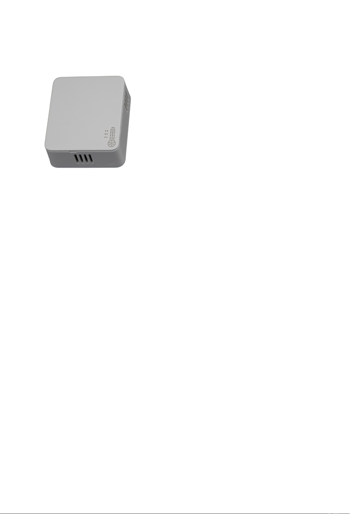
Figure 1: OY1110 Temperature and humidity sensor
The OY1110 LoRaWAN Temperature and humidity sensor is designed to measure
temperature and humidity in indoor environments. The sensor is intended for climate control,
energy optimization, and damage preventions in attics and basements. It is optimized for
reliable and secure measurements with more than 10 years life length.
The standard measurement and reporting interval is 15 minutes, other reporting intervals can
be configured over the air.
OY1110 LoRaWAN Temperature and humidity sensor, User manual, Version 1.0
Page 7
7
5 Installation and activation
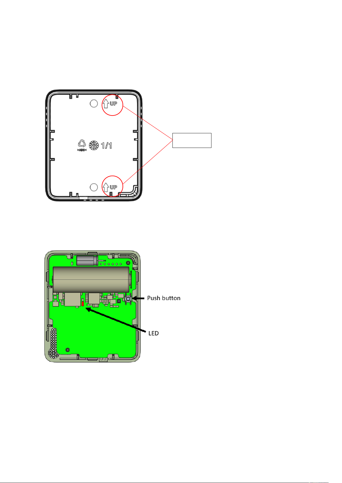
Note “UP”
The sensor consists of a bottom piece, to be mounted on the wall, and a top piece with the
active parts.
Figure 2: Mounting information
The bottom piece is mounted on the wall with the “UP” arrow upwards. It can be mounted
either with screws or adhesive tape.
Figure 3: Push button and LED
The top piece contains all active components. The unit is shipped in sleep mode, i.e. with all
functions, including radio, deactivated. The sensor is activated by pressing the push button for
3 seconds until the red LED makes two short flashes, make sure to not hold longer than 5
seconds. When the device has successfully joined the LoRaWAN network there will be a long
(2s) flash.
OY1110 LoRaWAN Temperature and humidity sensor, User manual, Version 1.0
Page 8
8
5.1 LoRaWAN Configuration
Configuration on the network server is done with
AppEUI: 70-B3-D5-D7-2F-F8-16-00 (a.k.a. JoinEUI)
It is possible to order a batch of devices configured with a customer unique AppEUI from the
Talkpool OUI range.
The device is configured with device unique DevEUI and AppKey
The device is default configured for OTA provisioning. Contact the Talkpool team for ABP
configuration. The device follows the LoRaWAN standard related Join configuration
parameters, such as RX1 and RX2 windows, RX2 downlink frequency etc.
The default setting is ADR enabled.
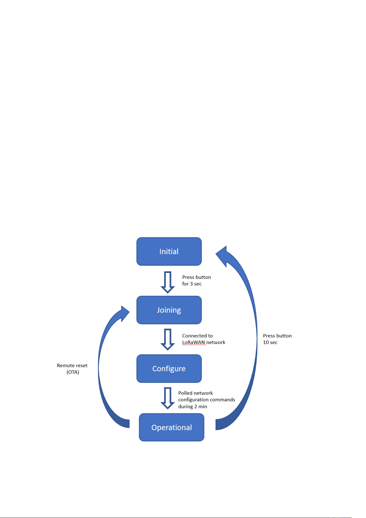
5.2 Sensor states and state check
The sensor has four states: Initial, Joining, Configure and Operational state.
Figure 4: Device states
OY1110 LoRaWAN Temperature and humidity sensor, User manual, Version 1.0
Page 9

9
To check the device state, press the button and hold it pressed until the red LED starts
State
Description
LED response
Initial
Low power state during transport. Radio not active.
1 short flash (0.5 sec)
Joining
Trying to join a LoRaWAN network. The device
will remain in this state until successfully joined a
LoRaWAN network
2 short flash (0.5 sec)
Configure
Enables quick over-the-air configuration, by polling
server after configuration commands during 2
minutes. This is done by sending uplink status
command (0x20).
1 long flash (2 sec)
Operational
Joined to a LoRaWAN network, measures
temperature and humidity periodically, and sends
measurement reports toward a LoRAWAN network.
1 long flash (2 sec)
flashing after 0.5s.
5.2.1 Re-join functionality
The device supervises its connectivity to the network, by monitoring that periodic downlink
messages are received.
The device tries to re-join the network if it has not heard anything from the network for 288
uplinks (3 days @ 15-minute message interval). The device requests and normally gets a
downlink ever 64th uplink due to the ADRAckReq functionality.
OY1110 LoRaWAN Temperature and humidity sensor, User manual, Version 1.0
Page 10

10
6 Specification
Accuracy and range
Temperature accuracy ± 0,2 °C (conditions 0 °C to +50 °C)
Temperature range -20 °C to +60 °C
Humidity accuracy ± 2% (conditions 10-90% RH)
Humidity range 0% to 100% non-condensing
Accuracy of ± 0,1 °C and ± 1,5% humidity available upon request
Connectivity
Network LoRaWAN
Frequency bands 868 MHz
Provisioning Over the air & personalization
Security
Algorithms AES-128
Hardware Cryptographic co-processor
Features Secure boot
Secure firmware upgrade
Hardware based ultra-secure key storage
Battery life
Battery life length 10 years (at 5-minute intervals, SF7)
Primary cell Lithium-thionyl 3.6V
Capacity 3.6 Ah
Size & Weight
Size 65 x 75 x 28 mm
Weight 75g
Configuration
Measurement intervals 1 minute – 1 week*
Transmission intervals 1 minute – 12 weeks*
*Default 15 minutes, configurable over the air
OY1110 LoRaWAN Temperature and humidity sensor, User manual, Version 1.0
Page 11

11
Unique App EUI available upon request
Enclosure
IP30
Certifications
RoHS compliant
CE
LoRaWAN
OY1110 LoRaWAN Temperature and humidity sensor, User manual, Version 1.0
Page 12

12
7 Product life length
The OY1110 LoRaWAN Temperature and Humidity sensor is design for 10+ years of
maintenance-free operation. The product has high quality, high capacity batteries which
support 15 min interval transmission at SF10 for 10 years. The product has soldered battery to
prevent problems with corrosion and oxidation on the battery terminals, which is a common
problem for batteries in field.
The protocol support also over the air adjustable measurement interval, and grouping
function, which enables flexible usage to optimize the product for fine time resolution or
extended life length.
8 Security
The OY1110 is based on the Talkpool LoRaWAN platform, with state-of-art security
solution. The device has secure boot, to ensuring the firmware integrity, prevents malware
injection and modification. The encrypted firmware prevents from any backwards engineering
to engineer attack vectors.
The security keys are generated and stored in an ultra-secure cryptographic co-processor and
cannot be extracted from the device.
The device is locked down in full security state, to keep the integrity and privacy of the
customer data.
9 Protocol
The protocol consists of different types of data
- LoRaWAN v.1.0.4 standard commands
- Unsolicited uplink status commands during configure state
- Periodic measurement reports
- Downlink commands and queries
- Uplink query response
Note 0x denotation means hexadecimal encoded.
9.1 LoRaWAN standard commands
All standard LoRaWAN v 1.0.4 are supported. Please refer to the LoRaWAN standard for the
protocol definition.
OY1110 LoRaWAN Temperature and humidity sensor, User manual, Version 1.0
Page 13

13
9.2 Unsolicited uplink status commands
The sensor polls the server for configuration parameters the during the Configure state. This
is done by sending unsolicited uplink status report (0x20). This is gives quick feedback to the
installer that the installation has been successful and enables downlink configuration
commands to be sent. After approximately 2 minutes the device changes to Operational
state.
Port: Port 1
Payload 0x01 20 00
0x01: Data type
0x20: Status command
0x00: Normal startup
The expected behavior is 0x01 20 00. If not contact Talkpool support.
9.3 Periodic measurement reports
The sensors transmit periodic unsolicited measurement reports, either from a single
measurement or grouping several measurements to one transmission to conserve energy.
9.3.1 Periodic single measurement report
The default configuration is that temperature and humidity is measured and transmitted every
15th minute and transmitted. The data is compressed to conserve energy and minimizing
interference.
Port: Port 2
Payload: Measurement value (see chap 9.3.3)
Size: 3 Bytes
9.3.2 Periodic grouped measurement report
To optimize the time granularity or extend the battery life length, several measurements can
be grouped into a single transmission.
Port: Port 3
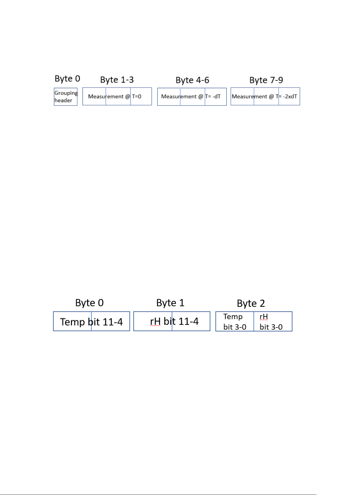
Payload: Grouping header, Measurement value (T=0), Measurement value (T=-dT),
Measurement value (T=-2 x dT), ….
OY1110 LoRaWAN Temperature and humidity sensor, User manual, Version 1.0
Page 14
14
Size: 1 Byte (Grouping header) + n x 3 Byte (Measurement value) where n = number of
grouped measurements
The latest measurement performed right before the transmission is sent first in the report. To
decode the number of measurements in a grouped measurement report the payload length
must be used. The time between the measurements (dT) are described in the Grouping header.
The data format is further explained in chapter 9.3.3 Measurement value and chapter 9.3.4
Grouping header.
9.3.3 Measurement value
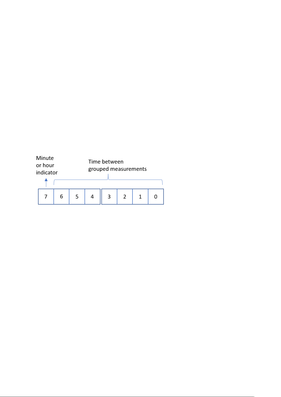
The measurement value for each measurement is sent as two unsigned 12-bit values coded in
three bytes.
Byte 0: Temperature, bit 11 – bit 4
Byte 1: Relative humidity, bit 11 – bit4
Byte 2:
bit 7-4: Temperature, bit 3 – bit 0
bit 3-0: Relative humidity, bit 3 – bit 0
Figure 5: Measurment value encoding
9.3.3.1 Temperature conversion
The temperature measurement is transmitted using an unsigned 12-bit value. The scaling is
1/10 °C and the offset is 80 °C, which means the received value should be subtracted by 800
and then divided with 10 to get it in °C.
See example in 9.3.5
OY1110 LoRaWAN Temperature and humidity sensor, User manual, Version 1.0
Page 15
15
9.3.3.2 Relative humidity conversion
The relative humidity (rH) measurement is transmitted using an unsigned 12-bit value. The
scaling is 1/10 % rH and the offset is 25 % rH, which means the received value should be
subtracted by 250 and then divided with 10 to get it in % rH.
See example in 9.3.5
9.3.4 Grouping header
A periodic grouped measurement report starts with a grouping header, with information of
time between the measurements, dT. The dT is coded using an 8-bit unsigned value. If bit7
(the most significant bit) is cleared (=0) the other 7 bits (bit0-bit6) indicates the number of
minutes between two measurements. If bit7 (the most significant bit) is set (=1) the other 7
bits (bit0-bit6) indicates the number of hours between two measurements.
9.3.5 Example: Single measurement report
Data with single measurement when TxGroupsSiz = 1 sent on LoRaWAN port 2
3E 44 1d
3E1: 993 => 19.3 gradC
44D: 1101 => 85.1 % Rh
9.3.6 Example: Grouped measurement report
Data with multiple measurements when TxGroupsSize = 3 and MeasurementInterval =
15 sent on LoRaWAN port 3
0F 2E 3C CD 33 38 D2 39 31 F5
Total length = 10 bytes. Header = 1 bytes, each measurement = 3 bytes. Then
number of measurements is (10-1)/3=3, i.e. 3 measurements
OY1110 LoRaWAN Temperature and humidity sensor, User manual, Version 1.0
Page 16

16
0F: Delta time. bit7 = 0 => minutes
Downlink command network => device
Field
Bytes
Value
Description
Note
Type
1
xx
0x01: Set
0x02: Query
0x03: Action
Index
1
xx
Command Index
Data
As defined for Command Index only applicable for set-commands
bit6-0 = 0F => 15 minutes
2EC: 748 => -5.2 °C now
3CD: 973 => 72.3 % Rh now
33D: 829 => 2.9 °C 15 minutes ago
382: 898 => 64.8 % Rh 15 minutes ago
39F: 927 => 12.7 °C 30 minutes ago
315: 789 => 53.9 % Rh 30 minutes ago
9.4 Downlink commands and queries
To control the sensor application, in-band commands and queries can be sent from the server
application. Contact your LoRaWAN network provider for in-band application API.
All downlink application communication is done on LoRaWAN port 1.
OY1110 LoRaWAN Temperature and humidity sensor, User manual, Version 1.0
Page 17

17
9.5 Commands
Port
Index
Description
Uplink
Datatype
response
Encoding
Valid range
Access
Unsolicited
Description
Note
1
0x03
FW build hash
6 x Uint8
Query
No
Unique number that identifies the
firmware version
1
0x05
Device reset
Action
No
Reset of device
1
0x06
CPU voltage
Uint8
25mV/
LSB
0-3.6V
Query
No
Read CPU voltage. Max/min ranges
depend on battery chemistry.
1
0x0A
CPU temperature
Uint16
Big endian
50C - 0.01C /
LSB
-50- +125 C
Query
No
Temperature from CPU sensor with 50
°C offset. Approximately 5 °C
accuracy.
1
0x20
Status
Uint8
Bitfield
Query
Yes
For Talkpool support troubleshooting
Cleared through
reset
1
0x23
Measurement
interval
Uint16
Big endian
Minutes
1-10080
Query
Set
No
Measurement interval in minutes
Setting
measurement
interval resets the
measurement
timer.
1
0x24
Tx group size
Uint8
-
1-12
Query
Set
No
Number of measurements to group in
each transmission.
2 - Data
[ Uint12,
Uint12 ]
(°C + 80)*10
(% Rh +25)*10
0 – 3800
0 - 1500
-
Yes
Current temperature and humidity. Sent
if TxGroupSize = 1
See Ch 6.3
3 - Grouped data
Uint8,
TxGroupSize *
[ Uint12,
Uint12 ]
min / hours
(°C + 80)*10
(% Rh +25)*10
1 min – 126
h
0 – 3800
0 - 1500
-
Yes
Groups of temperature and humidity
measurements. Sent if TxGroupSize >1.
Current measurement is sent first.
See Ch 6.3
OY1110 LoRaWAN Temperature and humidity sensor, User manual, Version 1.0
Page 18

18
9.5.1 Measurement interval
The measurements are done periodically. The interval time is controlled by the configuration
parameter Measurement Interval. The default setting is 15 minutes.
The measurement interval can be set between 1 and 10080 minutes (~1 week).
It is also possible to order a batch of OY1110 with a different default setting.
Example
Set measurement interval to 5 minutes: Port 1: 01230005
Set measurement interval to 15 minutes: Port 1: 0123000F
Note: For larger intervals than 2 hours, only full hours are supported. Maximal interval is 168
hours, i.e. 7 days.
9.5.2 TX group size
Several measurements can be grouped into a group measurement report to save battery. The
TX group command defines how many measurements that should be included in each
measurement report. The default setting is that every measurement as sent in a measurement
report, i.e. TX group size = 1.
Example:
Group three measurements in one measurement report: Port 1: 012403
Group one measurements in one measurement report: Port 1: 012401
Note: Only full hours are supported for measurement intervals longer than 2 hours. The
maximum interval is 168 hours, i.e. 7 days.
9.5.3 Reset device
The device can be remotely reset and forced into Joining state. All settings are back to
factory default.
Example: Remote device reset: Port 1: 0305
OY1110 LoRaWAN Temperature and humidity sensor, User manual, Version 1.0
Page 19

19
9.6 Uplink query response
Uplink command device => network
Field
Bytes
Value
Description
Note
Type
1
xx
0x01: Data
0x02: Command NACK
Index
1
xx
Command Index
Data
As defined for Command Index (only for Type: Data)
When communication on LoRaWAN port 1 the following header is used:
9.6.1 Uplink status report
The uplink status report is sent unsolicited during Configure state and queried in
Operational state.
Example: Port 1: 01 20 00
01: Data type
20: Status command
00: Normal startup
For non-zero data, an error has occurred. Provide the error code in contacts with
Talkpool support.
OY1110 LoRaWAN Temperature and humidity sensor, User manual, Version 1.0
 Loading...