

Page 1

WEBS-RETRO-MT/R4 Installation Instructions
Copyright 2009 Talk-A-Phone Co. All rights reserved.
Talk-A-Phone Co. • 7530 North Natchez Avenue • Niles, Illinois 60714-3804 Rev. 11/24/09
Phone 773.539.1100 • Fax 773.539.1241 • info@talkaphone.com • www.talkaphone.com
All prices and specifications are subject to change without notice.
Talk-A-Phone, Talk-A-Lert, Scream Alert and WEBS are registered trademarks of Talk-A-Phone Co.
I. Introduction
The WEBS-RETRO-MT/R4 is a kit that converts an existing ETP-MT/R OP 4 Tower into a WEBS®-capable Mass
Notification Unit. This instructions manual assumes that a fully functional ETP-MT/R OP 4 Tower has already
been installed.
II. Contents
Before beginning the installation, make sure you have all the included components. Each kit consists of three
packages, which include the painted WEBS® Retrofit tower top, the extra long replacement camera arm, and the
following components:
QTY
Part Number
Description
4
83073
WEBS® Loudspeaker
2
24651
Amplifier Mounting Bracket
2
NA
Paging Amplifier
2
NA
2’ Extension wire for WEBS® loudspeakers
4
42841
10-24 x 3/4" pan head tamperproof screw
2
42839
3/4"-10 hex nut
8
42840
3/4" washer
4
42847
10-24 Hex nuts for Amplifier Bracket
III. Installation
(A) Replacing the Tower Arm
1) Unplug the strobe light from the power supply and the emergency phone.
2) Unplug the optional CCTV camera from the power supply and all other devices (i.e. emergency
phone, network switch).
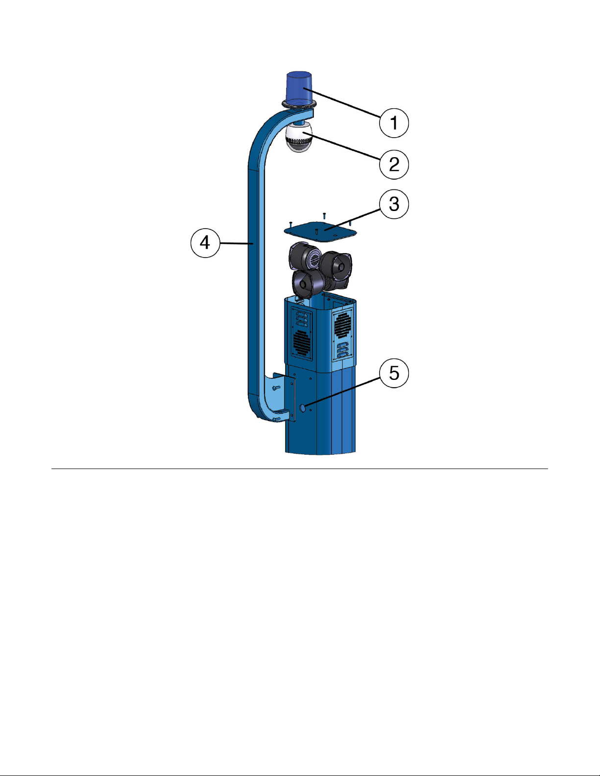
3) Remove the cap plate of the ETP-MT/R OP 4 tower top by unfastening three 10-24 x 3/4” pan head
tamperproof screws and keep them safely aside (See Figure 1).
4) Remove the ETP-MT/R4 OP 4 arm from the tower by unfastening four carriage bolts and keep them
safely aside. Pull out all cabling still attached to the strobe light and the optional CCTV camera from
the tower.
5) Take off the strobe light attached to the top of the ETP-MT/R4 OP 4 tower arm along with cabling and
reattach it to the new tower arm using the same screws.
6) Take off the optional CCTV camera attached to the bottom of the ETP-MT/R4 OP 4 tower arm along
with cabling and reattach it to the new tower arm using the same screws.
7) Feed all the cabling through the Cable Opening into the tower and reattach the new tower arm to the
ETP-MT/R OP 4 tower with the four carriage bolts included with the arm.
Page 2
WEBS-RETRO-MT/R4 Installation Instructions
Copyright 2009 Talk-A-Phone Co. All rights reserved.
Talk-A-Phone Co. • 7530 North Natchez Avenue • Niles, Illinois 60714-3804 Page 2 of 5
Phone 773.539.1100 • Fax 773.539.1241 • info@talkaphone.com • www.talkaphone.com
All prices and specifications are subject to change without notice.
Talk-A-Phone, Talk-A-Lert, Scream Alert and WEBS are registered trademarks of Talk-A-Phone Co.
Figure 1. Installing the WEBS® Tower Arm: (1) Strobe Light, (2) CCTV Camera, (3) Cap, (4) Tower Arm, (5) Cable Opening.
(B) Installing the Retrofit Tower Top
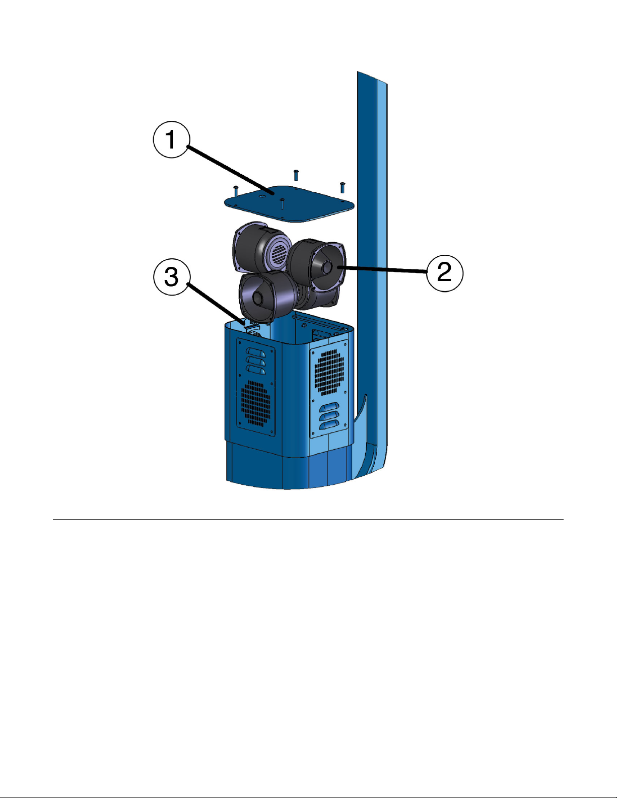
1) Fasten the Retrofit Top to the top of the tower with the help of the four 10-24 x 3/4" pan head
tamperproof screws provided.
2) Install the four WEBS® loudspeakers by locking each one of them down with the retainer bracket,
starting with the bottommost speakers first (see Figure 2).
3) Pass the speakers wiring through the center hole at the bottom of the Retrofit Top and down to the
bottom of the tower.
4) Close the top of the retrofit tower top with its cap plate with the help of the four 10-24 x 3/4” pan head
tamperproof screws that were set aside.
5) Reconnect the strobe light wiring to the emergency phone and to its power source. Reconnect the
optional CCTV camera to the power source and to all other devices.
Page 3
WEBS-RETRO-MT/R4 Installation Instructions
Copyright 2009 Talk-A-Phone Co. All rights reserved.
Talk-A-Phone Co. • 7530 North Natchez Avenue • Niles, Illinois 60714-3804 Page 3 of 5
Phone 773.539.1100 • Fax 773.539.1241 • info@talkaphone.com • www.talkaphone.com
All prices and specifications are subject to change without notice.
Talk-A-Phone, Talk-A-Lert, Scream Alert and WEBS are registered trademarks of Talk-A-Phone Co.
Figure 2. Installing the WEBS® Retrofit Tower Top: (1) Cap, (2) Loudspeaker, (3) Retainer Bracket.
(C) Installing Amplifiers
1) Remove the rear access panel from the ETP-MT/R OP 4 Tower.
2) Fasten amplifiers onto mounting plates with hex nuts provided.
3) Connect two WEBS® loudspeakers to each extension wire using the plug-in connectors. Connect the
other end of the cable to each one of the amplifiers using the COM and 25V screw terminals (it does
not matter which wire goes to which screw terminal).
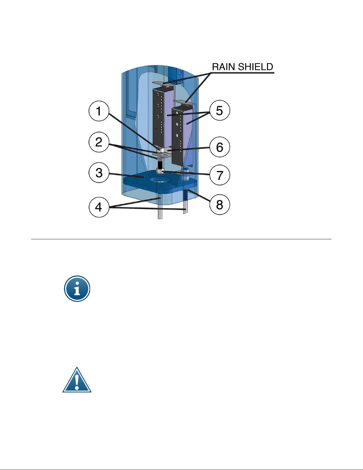
4) Place a washer along with the amplifier mounting bracket on the desired anchor bolt. After adjusting
the mounting plate with the help of the obround slotted hole, fasten the plate to the anchor bolt with
another washer and hex nut (see Figure 3).
Page 4
WEBS-RETRO-MT/R4 Installation Instructions
Copyright 2009 Talk-A-Phone Co. All rights reserved.
Talk-A-Phone Co. • 7530 North Natchez Avenue • Niles, Illinois 60714-3804 Page 4 of 5
Phone 773.539.1100 • Fax 773.539.1241 • info@talkaphone.com • www.talkaphone.com
All prices and specifications are subject to change without notice.
Talk-A-Phone, Talk-A-Lert, Scream Alert and WEBS are registered trademarks of Talk-A-Phone Co.
Figure 3. Installing the Paging Amplifier: (1) 3/4"-10 hex nut, (2) 3/4" washer, (3) Base plate of the tower, (4) Anchor bolts,
(5) Paging Amplifiers, (6) Amplifier Mounting Bracket, (7) 3/4"-10 hex nut for tightening anchor bolts, (8) 3/4"-10 hex nut for
leveling anchor bolts.
Depending on the length of threading available on the anchor bolt, you may need to use the
additional washers provided to elevate the amplifier mounting bracket so that the anchor bolt does
not interfere with the amplifier. If there is not enough threading available to install as shown above,
either do not use the additional washers, or remove the existing nut and washer and mount directly
above the tower base plate.
Because this kit is being added to existing towers, installers may find conduit, electrical boxes and
other objects obstructing the area above the anchor bolts where the amplifier brackets mount.
These brackets can be installed on any 2 of the 4 anchor bolts—if you find that it is not possible to
fit the brackets in the towers due to specifics of your existing installation, please call Talk-A-Phone
technical support for assistance.
5) Repeat steps 3 and 4 to install the second amplifier with a mounting bracket to the second anchor bolt
of an ETP-MT/R OP 4 Tower.
Although the amplifier mounting brackets have rain shields, it is the installer's obligation to ensure
that proper drip loops are created with the help of the extension wire, in order to prevent
condensation from damaging the amplifiers.
6) Connect the power supply to a paging amplifier, blue light/strobe and any other optional devices (e.g.
VOIP-CM-1.)
Page 5
WEBS-RETRO-MT/R4 Installation Instructions
Copyright 2009 Talk-A-Phone Co. All rights reserved.
Talk-A-Phone Co. • 7530 North Natchez Avenue • Niles, Illinois 60714-3804 Page 5 of 5
Phone 773.539.1100 • Fax 773.539.1241 • info@talkaphone.com • www.talkaphone.com
All prices and specifications are subject to change without notice.
Talk-A-Phone, Talk-A-Lert, Scream Alert and WEBS are registered trademarks of Talk-A-Phone Co.
7) Use the PAGE VOL screwdriver-adjustable control on the paging amplifier to adjust the volume of the
page output. Rotate the control clockwise to increase the volume and counterclockwise to decrease
the volume.
8) Reattach the rear access panel.
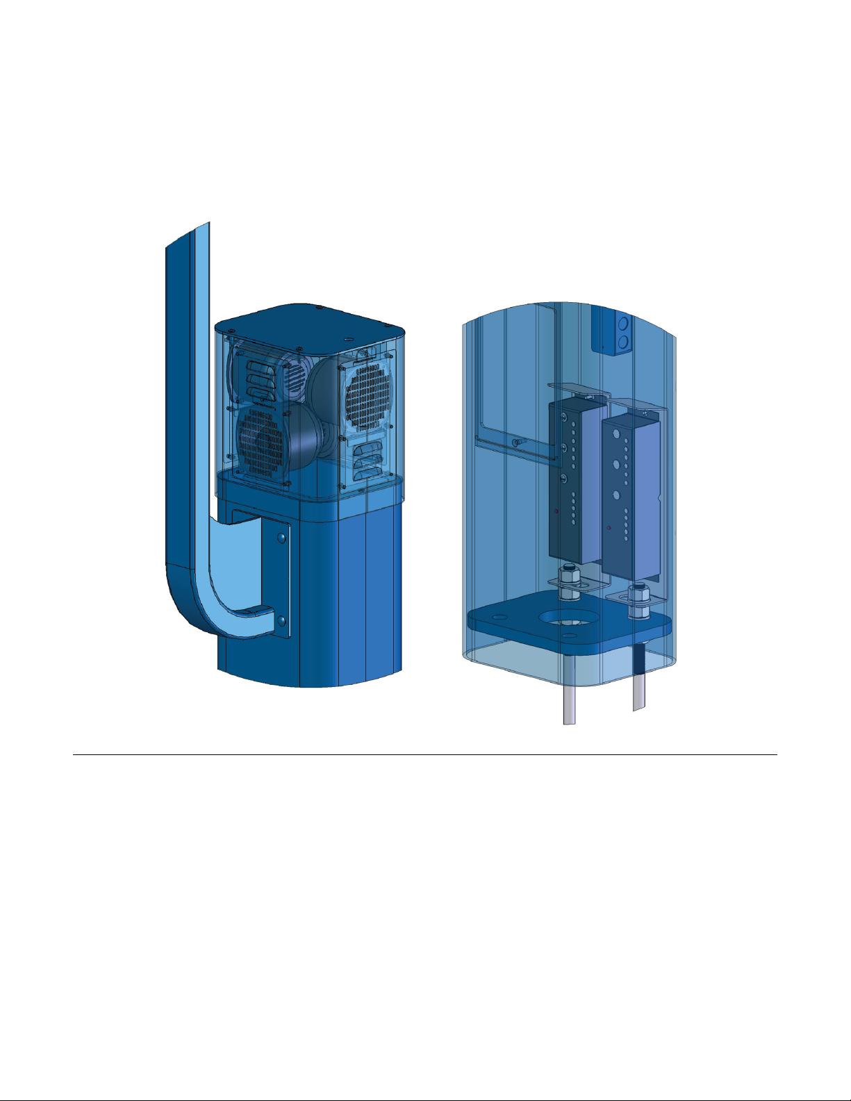
Figure 4. Fully assembled WEBS-RETRO-MT/R4 showing Retrofit Tower Top and Paging Amplifier kit (wiring not
shown)
 Loading...