

Page 1
QTY
Part Number
Description
4
42838
J-Bolts
1
26312
Cardboard Template
QTY
Part Number
Description
8
42839
3/4"-10 Hex Nut
8
42840
3/4" Washer
3
42841
10-24 x 3/4" Pan Head Tamper-proof Screw
2
42843
6-32 Hex Nut
1
67478
Polycarbonate Light Cover
1
68590
LED Faceplate Light
1
68559
LED Blue Light (12/24VDC)
QTY
Part Number
Description
1
WEBS-TERMINAL
Terminal Blocks on DIN rail
1
WEBS-MIC
Local Paging Microphone
1
WEBS-AMP-1
Paging Amplifier
1
WEBS-VCU
WEBS-Volume Control Unit
4
19667
RCA Audio Cable
18
4247
8-32 x 1/2” Slotted Pan Head Screw
4
42847
8-32 Hex Nut
2
67475
Gel-filled Wire Nut
2
6748
Wire Nut
1
WEBS-PSU
Power Supply 12VDC (not included if WEBS-BACKUP is used)
WEBS-MT/R Tower Installation Instructions
I. Introduction
This manual is for tower installation only. For instructions on installing the anchor bolts into the
foundation, see the ETP-MT/R Anchor Bolt Installation Instructions.
II. Contents
Before beginning installation, make sure you have all the included components. Each WEBS-MT/R tower
consists of the following packages. Package #1 contains the WEBS-MT/R tower itself. Package #2,
labeled MT/R BOLT KIT contains the anchor bolt install kit. Package #3, labeled TOWER PTS, contains
the tower hardware and lighting installation kit. Package #4, labeled WEBS-MT/R-KIT contains the WEBS
paging kit. Package #5, labeled WEBS-BACKUP (sold separately) contains the WEBS power back-up kit.
Emergency phones are sold and shipped separately (with mounting screws included).
MT/R BOLT KIT
TOWER PTS
WEBS-MT/R-KIT
Copyright 2014 Talk-A-Phone Co. All rights reserved. Rev. 5/16/2014
Talk-A-Phone, Talk-A-Lert, Scream Alert and WEBS are registered trademarks of Talk-A-Phone Co.
Talk-A-Phone Co. • 7530 North Natchez Avenue • Niles, Illinois 60714-3804
Phone 773.539.1100 • Fax 773.539.1241 • info@talkaphone.com • www.talkaphone.com
All prices and specifications are subject to change without notice.
Page 2
WEBS-MT/R Tower Installation Instructions
QTY
Part Number
Description
1
86383
WEBS-UPS
2
68594
12VDC Battery
1
25192
Mounting shelf for battery
4
4247
Screws #8-32 x 0.5”L
18
4248
Hex nut #8-32
18
42767
#10 round hole washer
WEBS-BACKUP (optional)
III. Physical Installation
1. Install one 3/4” nut and one washer on each anchor bolt 2.5”-3.5" above grade to top of washer. This
will allow for a 1/2" air gap between the foundation and the tower which will allow airflow and prevent
moisture problems. Verify that the nuts are level (0° pitch).
NOTE: To insure proper grounding of all electrical components, the tower mount should be effectively earth grounded
from the grounding stud (located across from the lower access panel) with 6 AWG or better insulated, stranded copper
wire to the metallic power service raceway (conduit) or an 8' or longer corrosion-resistant ground spike.
2. After removing the lower access panel of the tower, install the tower onto the bolts with the
Emergency Phone opening oriented in the desired direction. Install second set of nuts and washers.
Tighten the upper nuts; the bottom set is only for leveling.
Copyright 2014 Talk-A-Phone Co. All rights reserved. Page 2 of 9
Talk-A-Phone Co. • 7530 North Natchez Avenue • Niles, Illinois 60714-3804
Phone 773.539.1100 • Fax 773.539.1241 • info@talkaphone.com • www.talkaphone.com
All prices and specifications are subject to change without notice.
Talk-A-Phone, Talk-A-Lert, Scream Alert and WEBS are registered trademarks of Talk-A-Phone Co.
Page 3
WEBS-MT/R Tower Installation Instructions
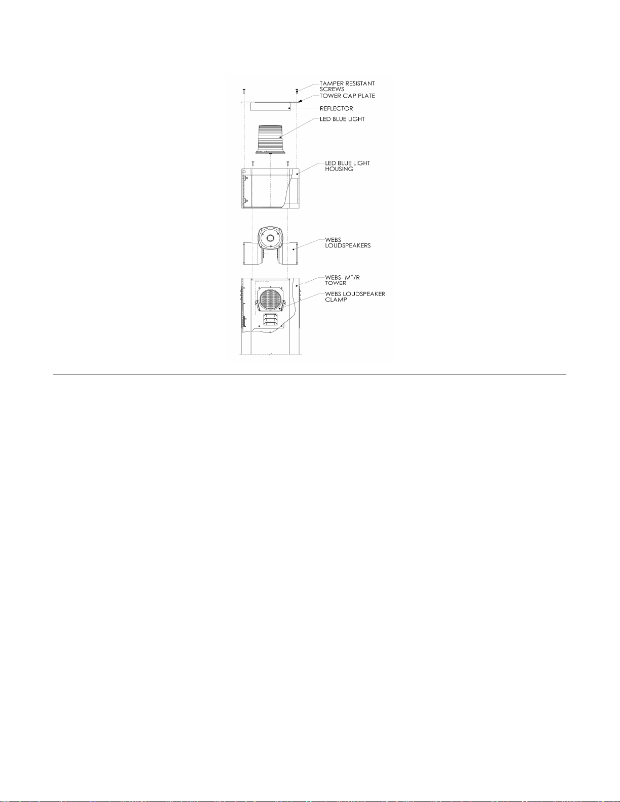
Figure 1. Installing the LED Blue Light.
3. Take off the tower cap plate as shown in Figure 1. Install the LED Blue Light to the base of the LED
blue light housing. Reattach the tower cap plate.
4. Remove the rear access panel (top) of the tower and mount the paging amplifier vertically aligned
(power connection / speaker output side facing up and audio input side facing down) with the help of
four (4) #10-32 screws and nuts provided. Also mount the WEBS-VCU on to the upper mounting
panel of the tower as shown in Figure 2. Connect the paging amplifier audio input channels to the
respective audio outputs on the WEBS-VCU via RCA audio cables provided. (e.g. Amplifier audio
input channel 1 to WEBS-VCU audio output 1).
Copyright 2014 Talk-A-Phone Co. All rights reserved. Page 3 of 9
Talk-A-Phone Co. • 7530 North Natchez Avenue • Niles, Illinois 60714-3804
Phone 773.539.1100 • Fax 773.539.1241 • info@talkaphone.com • www.talkaphone.com
All prices and specifications are subject to change without notice.
Talk-A-Phone, Talk-A-Lert, Scream Alert and WEBS are registered trademarks of Talk-A-Phone Co.
Page 4

WEBS-MT/R Tower Installation Instructions
Figure 2. Installing the Paging Amplifier and the WEBS-Volume Control Unit (WEBS-VCU).
5. If using the WEBS-BACKUP option, place the mounting shelf on the two L-brackets located in the
lower section of the tower. Rest the batteries in the upright position on the shelf. Mount the WEBSUPS-84-20 on to the mounting panel and secure the assembly in place onto the mounting screws
provided.
Connect the DC output end (black and white color cables with gray jacket and fuse one end) to the
DIN Rail Terminal Block, terminal no. 23 and 25 as shown in Table 1.
Connect the battery input cables (red and black cable with ring terminals on each end) to the
terminals of one battery (Red cable to the positive terminal of the battery and black cable to the
negative terminal of the battery). Repeat the same procedure for the second battery.
Connect the 120 VAC input cable (cable with three prong connector on end) to a 120VAC power
source.
OR
Install the power supply at a convenient position on the mounting panel provided. Connect the power
supply to 120 VAC on one end and connect the other end to the DIN Rail Terminal Block, terminal no.
23 and 25 as shown in Table 1.
Copyright 2014 Talk-A-Phone Co. All rights reserved. Page 4 of 9
Talk-A-Phone Co. • 7530 North Natchez Avenue • Niles, Illinois 60714-3804
Phone 773.539.1100 • Fax 773.539.1241 • info@talkaphone.com • www.talkaphone.com
All prices and specifications are subject to change without notice.
Talk-A-Phone, Talk-A-Lert, Scream Alert and WEBS are registered trademarks of Talk-A-Phone Co.
Page 5

WEBS-MT/R Tower Installation Instructions
Terminal
# (Side A)
Connection
Terminal
# (Side B)
Connection
1 30 2 31 3
Emergency Phone AUX. Output # 2
32
LED Blue Light [Orange]
4
Emergency Phone AUX. Output # 2
33
LED Blue Light [Black]
5
Emergency Phone AUX. Output # 3
34
Auxiliary Device Trigger Wire
6
Emergency Phone AUX. Output # 3
35
Auxiliary Device Trigger Wire
7
WEBS-VCU — 12 VDC Trigger [Orange]
36
Paging Amplifier —12 VDC Trigger [Orange]
8
WEBS-VCU — Ground [Black]
37
Paging Amplifier — Ground [Black]
9
Local Paging Microphone — 12 VDC [White]
38
WEBS- VCU [Microphone Input] — 12 VDC
[White]
10
Local Paging Microphone — 12 VDC Trigger
[Green]
39
WEBS- VCU [Microphone Input] — 12 VDC
Trigger [Green]
11
Local Paging Microphone — Audio(+) [Red]
40
WEBS-VCU [Microphone Input] — Audio (+)
[Red]
12
Local Paging Microphone — Audio(-) [Black]
41
WEBS- VCU [Microphone Input] – Audio (-)
[Black]
13
WEBS-CM-2 / VOIP-500 (AUX. Output # 1)
OR WEBS-ZPS — 12 VDC Trigger [Green]
42
WEBS- VCU [WEBS-CM-2 OR WEBS-ZPS
Input] — 12 VDC Trigger [Green]
14
WEBS-CM-2 / VOIP-500 (AUX. Output # 1)
OR WEBS-ZPS — 12 VDC [White]
43
WEBS- VCU [WEBS-CM-2 OR WEBS-ZPS
Input] — 12 VDC [White]
15
WEBS-CM-2 / VOIP-500 OR WEBS-ZPS —
Audio (+) [Red]
44
WEBS- VCU [WEBS-CM-2 OR WEBS-ZPS
Input] — Audio (+) [Red]
16
WEBS-CM-2 / VOIP-500 OR WEBS-ZPS —
Audio (-) [Black]
45
WEBS- VCU [WEBS-CM-2 OR WEBS-ZPS
Input] — Audio (-) [Black]
17
WEBS-ZPS — Bare Shield [Yellow]
46
WEBS- VCU [WEBS-CM-2 OR WEBS-ZPS
Input] — Bare Shield [Yellow]
18
Not Used
47
WEBS-CM-2 – 12 VDC Power (-) [Black]
19
Not Used
48
Face Plate Light – 12 VDC Power (-) [Black]
20
Not Used
49
LED Blue Light — 12 VDC Power (-) [Black]
21
Not Used
50
Paging Amplifier – 12 VDC Power (-) [Black]
22
Not Used
51
WEBS-VCU / Paging Amplifier Shield
23
Power Supply / Battery — 12 VDC (-)
[Black]
52
WEBS-VCU – 12 VDC Power (-) [Black or
Green]
24
Connect to GROUND
53
GROUND
25
Power Supply / Battery — 12 VDC (+) [Red
or White]
54
WEBS-VCU — 12 VDC Power (+) [Red or
Brown]
26
Not Used
55
Paging Amplifier — 12 VDC Power (+) [Red
or White]
27
Not Used
56
LED Blue Light — 12 VDC Power (+) [White]
28
Not Used
57
Face Plate Light — 12 VDC Power (+) [Red]
29
Not Used
58
WEBS-CM-2 — 12 VDC Power (+) [Red]
Table 1. WEBS-MT/R DIN Rail Terminal Block Connections.
Copyright 2014 Talk-A-Phone Co. All rights reserved. Page 5 of 9
Talk-A-Phone, Talk-A-Lert, Scream Alert and WEBS are registered trademarks of Talk-A-Phone Co.
Talk-A-Phone Co. • 7530 North Natchez Avenue • Niles, Illinois 60714-3804
Phone 773.539.1100 • Fax 773.539.1241 • info@talkaphone.com • www.talkaphone.com
All prices and specifications are subject to change without notice.
Page 6

WEBS-MT/R Tower Installation Instructions
6. Install the LED light board over the phone opening. A polycarbonate light cover protects the LED light
assembly from the inside. Peel the protective paper off the light cover and fit it onto the studs inside
the tower. Slide the LED board over the studs with the LEDs facing down. The built-in spacers will
keep the LEDs from resting on the acrylic window. Tighten down using the enclosed nuts. Be careful
not to over tighten to avoid cracking the circuit board.
7. Install the DIN rail on the two welds studs behind the phone opening. Install the local paging
microphone and mounting bracket inside the microphone compartment as shown in Figure 3. Attach
the instructional label below (provided) on to the inner surface of the microphone compartment door.
NOTE: The microphone gets activated two seconds after depressing the microphone switch.
Figure 3. Installing the Local Paging Microphone, DIN Rail Terminal Block and Emergency Phone.
8. Attach the Emergency Phone to the tower with six (6) 10-24 oval head tamperproof screws (included
with the phone). When using an ETP-400 Series Emergency Phone connect the phone line coming
into the tower to the male RJ11 connector coming from the Emergency Phone. An outdoor rated
RJ11 female modular jack on the end of the incoming phone line is strongly recommended.
9. Re-attach the rear access panels to the tower.
NOTE: It is the installer’s obligation to ensure compliance with all national, regional, and local
regulations. ALL WIRING MUST USE DRIP-LOOPS.
Copyright 2014 Talk-A-Phone Co. All rights reserved. Page 6 of 9
Talk-A-Phone Co. • 7530 North Natchez Avenue • Niles, Illinois 60714-3804
Phone 773.539.1100 • Fax 773.539.1241 • info@talkaphone.com • www.talkaphone.com
All prices and specifications are subject to change without notice.
Talk-A-Phone, Talk-A-Lert, Scream Alert and WEBS are registered trademarks of Talk-A-Phone Co.
Page 7

WEBS-MT/R Tower Installation Instructions
PAGING
AMPLIFIER
Power
Connections
Power - [RED]
Power - [BLACK]
Trigger – [ORANGE]
POWER CABLE
[RED or WHITE]
[BLACK]
TRIGGER CABLE
[WHITE]
[ORANGE-
WHITE]
[RED or WHITE]
[BLACK]
[WHITE]
[ORANGE-
WHITE]
55
50
37
36
}
To DIN Rail
Terminal Block
Audio
Output
Audio
Input
[PURPLE]
[GREEN]
[GREY]
[WHITE]
{
To Speaker
Cables
RCA Cable 1
RCA Cable 2
RCA Cable 3
RCA Cable 4
}
To Audio Output on
WEBS-VCU
Speaker No.
Amplifier Cable
Speaker #1
White and White/Black
Speaker #2
Grey and Grey/Black
Speaker #3
Green and Green/Black
Speaker #4
Purple and Purple/Black
IV. Wiring Installation
1. Make all connections to the DIN Rail Terminal Block as shown in Table 1.
2. Connect the Paging Amplifier to the WEBS Loudspeakers, DIN Rail Terminal Block and the WEBS-
VCU as shown in Figure 4. Connect the speaker audio cables to their corresponding paging amplifier
speaker output cables as follows:
Figure 4. Paging Amplifier, WEBS Loudspeakers, WEBS-VCU and DIN Rail Terminal Block Connectivity Layout
Copyright 2014 Talk-A-Phone Co. All rights reserved. Page 7 of 9
Talk-A-Phone Co. • 7530 North Natchez Avenue • Niles, Illinois 60714-3804
Phone 773.539.1100 • Fax 773.539.1241 • info@talkaphone.com • www.talkaphone.com
Talk-A-Phone, Talk-A-Lert, Scream Alert and WEBS are registered trademarks of Talk-A-Phone Co.
All prices and specifications are subject to change without notice.
Page 8

WEBS-MT/R Tower Installation Instructions
38
Paging
Amplifier
WEBS-VCU
Microphone Input
WEBS-CM-2 /
WEBS-ZPS Input
Audio
Output 1
Power / Trigger
Audio
Output 3
Audio
Output 4
Audio
Output 2
[WHITE]
[GREEN]
[RED]
[BLACK]
[BLACK]
[RED]
[WHITE]
[YELLOW] –
BARE SHIELD
[GREEN]
RCA CABLE 1
RCA CABLE 2
RCA CABLE 3
RCA CABLE 4
}
39
40
41
42
43
44
45
46
{
{
To DIN Rail
Terminal Block
To DIN Rail
Terminal Block
[RED / BROWN]
[BLACK / GREEN]
[WHITE]
[ORANGE-
WHITE]
7
8
52
54
VOIP-500 /
WEBS-CM-2
Audio Output
Auxiliary Output
[Dry Contact Closure]
[GREEN]
[WHITE]
[RED]
Audio Line Level
Twisted Shielded
Pair Cable
Twisted One Pair Shielded
And One Pair Unshielded Cable
[BLACK]
[RED]
[BLACK]
[WHITE]
[GREEN] 13
14
15
16
}
To DIN Rail Terminal
Block
3. Connect the WEBS-VCU and the DIN Rail Terminal Block as shown in Figure 5. If using the IP
paging module (WEBS-CM-2 or VOIP-500 Series Emergency Phone), connect the respective wires
to the WEBS-CM-2 Input port on the WEBS-VCU. If using the analog paging module (WEBS-ZPS)
connect the respective wires to the WEBS-ZPS Input port on the WEBS-VCU. The unused cable
wires should be individually insulated from each other.
Figure 5. WEBS-VCU, Paging Amplifier and DIN Rail Terminal Block Connectivity Layout
4. When using WEBS-CM-2 or VOIP-500 Series Emergency Phone make connections to the DIN Rail
Terminal Block as shown in Figure 6.
Figure 6. VOIP-500 / WEBS-CM-2 and DIN Rail Terminal Block Connectivity Layout
Copyright 2014 Talk-A-Phone Co. All rights reserved. Page 8 of 9
Phone 773.539.1100 • Fax 773.539.1241 • info@talkaphone.com • www.talkaphone.com
Talk-A-Phone, Talk-A-Lert, Scream Alert and WEBS are registered trademarks of Talk-A-Phone Co.
Talk-A-Phone Co. • 7530 North Natchez Avenue • Niles, Illinois 60714-3804
All prices and specifications are subject to change without notice.
Page 9

WEBS-MT/R Tower Installation Instructions
NC
NO
RLY
ONE
IN
RT
BGM
SRC
GND ST
COM
RLY
ONE
NC
COM
NO
OUT
RT
PA
IN
RT
HPBGM
IN
RT
LPBGM
IN
RT
PA
EM/SC
AUX
GND
+12 VDC
GND
-1.5 A
(+)
(-)
ZONE A
IN
RT
LOCAL
BGM
RD A
RD C
RD COM
RD B
(+)
(-)
ZONE B
(+)
(-)
ZONE C
(+)
(-)
ZONE A
IN
RT
LOCAL
BGM
RD A
RD C
RD COM
RD B
(+)
(-)
ZONE B
(+)
(-)
ZONE C
(+)
(-)
ZONE A
IN
RT
LOCAL
BGM
RD A
RD C
RD COM
RD B
(+)
(-)
ZONE B
(+)
(-)
ZONE C
MODEL
WEBS- ZPS
22 AWG wire
[RED]
[BLACK]
[GREEN]
[YELLOW]
Bare Shield
[WHITE]
One Pair Twisted Shielded with Bare Wire
One Pair Unshielded
[WHITE]
[RED]
[BLACK]
[GREEN]
[YELLOW]
Bare Shield
13
14
15
16
}
To DIN Rail
Terminal Block
17
5. When using the WEBS-ZPS make connections to the DIN Rail Terminal Block as shown in Figure 7.
Figure 7. WEBS-ZPS and DIN Rail Terminal Block Connectivity Layout
Copyright 2014 Talk-A-Phone Co. All rights reserved. Page 9 of 9
Talk-A-Phone Co. • 7530 North Natchez Avenue • Niles, Illinois 60714-3804
Phone 773.539.1100 • Fax 773.539.1241 • info@talkaphone.com • www.talkaphone.com
All prices and specifications are subject to change without notice.
Talk-A-Phone, Talk-A-Lert, Scream Alert and WEBS are registered trademarks of Talk-A-Phone Co.
 Loading...