

Page 1

Rev. 7/2/2014
Copyright 2014 Talk-A-Phone Co. • 7530 North Natchez Avenue • Niles, Illinois 60714 • Phone 773.539.1100 • info@talkaphone.com • www.talkaphone.com.
All prices and specifications are subject to change without notice. Talkaphone, Talk-A-Lert, and WEBS are registered trademarks of Talk-A-Phone Co. Windows is a trademark
of Microsoft Corporation. All other trademarks are the property of their respective owners.
Installation and Operation Manual
for
Talkaphone Voice over IP Interface
VOIP-1-2-4-8
Page 2

VOICE OVER IP INTERFACE
Installation and Operation Manual
2
CHAPTER 1
Introduction to Voice over IP Interfaces
(VOIP-1, VOIP-2, VOIP-4, and VOIP-8)
The Voice over IP (VoIP) Interface allows all Talkaphone Emergency Phones to be used over an IP data
network. The VOIPs integrate seamlessly with existing VoIP phone systems, and support standard VoIP
protocols. For sites without existing VoIP systems, two VOIPs can be used in conjunction to send
emergency calls over the IP network and then remotely “jump off” onto an existing PBX or PSTN phone
network.
Figure 1-1: VOIP-1 Chassis
Figure 1-2: VOIP-2 Chassis
Figure 1-3: VOIP-4/VOIP-8 Chassis
Capacity. Talkaphone’s VOIP-8 model is an eight-channel unit, the model VOIP-4 is a four-channel unit,
the model VOIP-2 is a two-channel unit, and the VOIP-1 is a single-channel unit. All of these VoIP units
have a 10/100Mbps Ethernet interface and a command port for configuration.
Mounting. Mechanically, the VOIP-4 and VOIP-8 units are designed for a one-high industry-standard EIA
19-inch rack enclosure. By contrast, the VOIP-1 and the VOIP-2 are not rack mountable.
Phone System Transparency. These VOIP-1-2-4-8’s interoperate with a telephone switch or PBX,
acting as a switching device that directs voice and fax calls over an IP network. The VOIP-1-2-4-8 units
have “phonebooks,” directories that determine to whom calls may be made and the sequences that must
be used to complete calls through the VOIP-1-2-4-8. The phonebooks allow the phone user to interact
with the VOIP system just as they would with an ordinary PBX or telco switch. When the phonebooks are
set, special dialing sequences are minimized or eliminated altogether. Once the call destination is
determined, the phonebook settings determine whether the destination VOIP unit must strip off or add
dialing digits to make the call appear at its destination to be a local call.
Page 3

VOICE OVER IP INTERFACE
Installation and Operation Manual
3
H. 323, SIP, & SPP. Being H.323 compatible, the VOIP-1-2-4-8 units can place calls to telephone
equipment at remote IP network locations that also contain H.323 compatible voice-over-IP gateways. It
will interface with H.323 software and H.323 gatekeeper units. H.323 specifications also bring to VoIP
telephony many special features common to conventional telephony. H.323 features of this kind that have
been implemented into the VOIP-1-2-4-8 units include Call Hold, Call Waiting, Call Identification, Call
Forwarding (from the H.450 standard), and Call Transfer (H.450.2 from H.323 Version 2). The fourth
version of the H.323 standard improves system resource usage (esp. logical port or socket usage) by
handling call signaling more compactly and allowing use of the low-overhead UDP protocol instead of the
error-correcting TCP protocol where possible.
The VOIP-1-2-4-8 is also SIP-compatible. (“SIP” means Session Initiation Protocol.) However, H.450
Supplementary Services features can be used under H.323 only and not under SIP. It can register with
SIP proxy servers and call managers that are 100% SIP-compliant.
SPP (Single-Port Protocol) is a non-standard protocol that offers advantages in certain situations,
especially when firewalls are used and when dynamic IP address assignment is needed. However, when
SPP is used, certain features of SIP and H.323 will not be available and SPP will not interoperate with
VoIP systems using H.323 or SIP.
Data Compression & Quality of Service. The VOIP-1-2-4-8 unit comes equipped with a variety of data
compression capabilities, including G.723, G.729, and G.711 and features DiffServ quality-of-service
(QoS) capabilities.
PSTN Failover Feature. The VOIP-2-4-8 can be programmed to divert calls to the PSTN temporarily in
case the IP network fails. Enabling this feature will require a dedicated channel, therefore a VOIP-1 does
not have the PSTN failover feature.
Management. Configuration and system management can be done locally with the VOIP-1-2-4-8
configuration software via a serial connection. After an IP address has been assigned locally, other
configuration can be done remotely using the Web Interface GUI. All of these control software packages
are included on the VOIP-1-2-4-8 CD.
While the Web GUI’s appearance differs slightly, its content and organization are essentially the same as
that of the Windows GUI (except for logging).
The primary advantage of the Web GUI is remote access for control and configuration. The controller PC
and the VOIP-1-2-4-8 unit itself must both be connected to the same IP network and their IP addresses
must be known.
The Windows GUI gives access to commands via icons and pulldown menus, whereas the Web GUI
does not. The Web GUI, however cannot perform logging in the same direct mode done in the Windows
GUI. However, when the Web GUI is used, logging can be done by e-mail (SMTP).
Page 4
VOICE OVER IP INTERFACE
Installation and Operation Manual
4
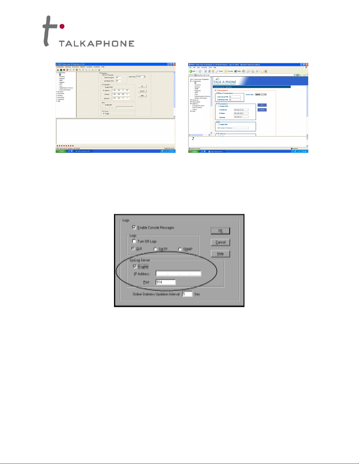
Figure 1-4: VOIP Interface Windows GUI (left) and Web Interface GUI (right)
Once you’ve begun using the web browser GUI, you can go back to the Windows GUI at any time.
However, you must log out of the web browser GUI before using the Windows GUI.
Logging of System Events. The software for the VOIP-1-2-4-8 units has SysLog Server functionality.
SysLog is a de facto standard for logging events in network communication systems.
Figure 1-5: Syslog Functionality in VOIP-1-2-4-8 Interface Units
The SysLog Server resides in the VOIP-1-2-4-8 unit itself. To implement this functionality, you will need a
SysLog client program (sometimes referred to as a “daemon”).
Supplementary Telephony Services. The H.450 standard (an addition to H.323) brings to VoIP
telephony more of the premium features found in PSTN and PBX telephony. VOIP-1-2-4-8 units offer five
of these H.450 features: Call Transfer, Call Hold, Call Waiting, Call Name Identification (not the same as
Caller ID), and Call Forwarding. (The first four features are found in the “Supplementary Services”
window; the fifth, Call Forwarding, appears in the
Add/Edit Inbound phonebook screen.) Note that the first three features are closely related. All of these
H.450 features are supported for H.323 operation only; they are not supported for SIP or SPP.
Page 5
VOICE OVER IP INTERFACE
Installation and Operation Manual
5
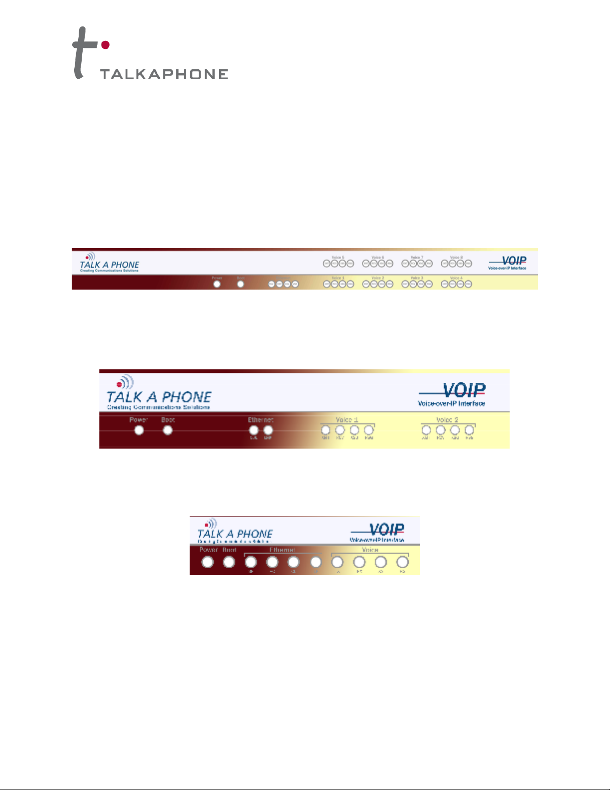
VOIP-1-2-4-8 Front Panel LEDs
LED Types. The VOIP-1-2-4-8 units have two types of LEDs on their front panels:
(1) general operation LED indicators (for power, booting, and Ethernet functions), and
(2) channel operation LED indicators that describe the data traffic and performance in each VoIP
data channel.
Active LEDs. On both the VOIP-4 and VOIP-8, there are eight sets of channel-operation LEDs.
However, on the VOIP-4, only the lower four sets of channel-operation LEDs are functional. On the VOIP8, all eight sets are functional.
Figure 1-6. VOIP-4/VOIP-8 LEDs
Similarly, the VOIP-2 has the general-operation indicator LEDs and two sets of channel-operation LEDs,
one for each channel.
Figure 1-7. VOIP-2 LEDs
Finally, the VOIP-1 has the general-operation indicator LEDs and a set of channel-operation LEDs for its
single VoIP channel.
Figure 1-8. VOIP-1 LEDs
Page 6

VOICE OVER IP INTERFACE
Installation and Operation Manual
6
VOIP-1 LED Description
VOIP-1 Front Panel LED Definitions
LED NAME
DESCRIPTION
General Operation LEDs
Power
Indicates presence of power.
Boot
After power up, the Boot LED will be on briefly while the
VOIP-1 is booting. It lights whenever the VOIP-1 is booting or
downloading a setup configuration data set.
Ethernet
FDX. LED indicates whether Ethernet connection is half-
duplex or full-duplex (FDX) and, in half-duplex mode,
indicates occurrence of data collisions. LED is on constantly
for full-duplex mode; LED is off constantly for half-duplex
mode. When operating in half-duplex mode, the LED will flash
during data collisions. LNK. Link/Activity LED. This LED is lit if
Ethernet connection has been made. It is off when the link is
down (i.e., when no Ethernet connection exists). While link is
up, this LED will flash off to indicate data activity.
Channel-Operation LEDs
TX
Transmit. This indicator blinks when voice packets are being
transmitted to the local area network.
RX
Receive. This indicator blinks when voice packets are being
received from the local area network.
XS
Transmit Signal. This indicator lights when the FXS-
configured channel is off-hook or the FXO-configured channel
is receiving a ring from the Telco or PBX.
RS
Receive Signal. This indicator lights when the FXS-
configured channel is ringing or the FXO-configured channel
has taken the line off-hook.
Page 7

VOICE OVER IP INTERFACE
Installation and Operation Manual
7
VOIP-2-4-8 LED Descriptions
VOIP-2/VOIP-4/VOIP-8 Front Panel LED Definitions
LED NAME
DESCRIPTION
General Operation LEDs (one set on each VoIP Interface model)
Power
Indicates presence of power.
Boot
After power up, the Boot LED will be on briefly while the
VOIP-2-4-8 is booting. It lights whenever the VOIP-2-4-8 is
booting or downloading a setup configuration data set.
Ethernet
FDX. LED indicates whether Ethernet connection is half-
duplex or full-duplex (FDX) and, in half-duplex mode,
indicates occurrence of data collisions. LED is on constantly
for full-duplex mode; LED is off constantly for half-duplex
mode. When operating in half-duplex mode, the LED will flash
during data collisions. LNK. Link/Activity LED. This LED is lit if
Ethernet connection has been made. It is off when the link is
down (i.e., when no Ethernet connection exists). While link is
up, this LED will flash off to indicate data activity.
Channel-Operation LEDs (one set for each channel)
XMT
Transmit. This indicator blinks when voice packets are being
transmitted to the local area network.
RCV
Receive. This indicator blinks when voice packets are being
received from the local area network.
XSG
Transmit Signal. This indicator lights when the FXS-
configured channel is off-hook, the FXO-configured channel
is receiving a ring from the Telco, or the M lead is active on
the E&M configured channel. That is, it lights when the VOIP2-4-8 is receiving a ring from the PBX.
RSG
Receive Signal. This indicator lights when the FXS-
configured channel is ringing, the FXO-configured channel
has taken the line off-hook, or the E lead is active on the
E&M-configured channel.
Page 8

VOICE OVER IP INTERFACE
Installation and Operation Manual
8
Computer Requirements
Minimum Requirements for Windows GUI:
The computer on which the VOIP-1-2-4-8 units’ configuration program is installed must meet these
requirements:
• must be IBM-compatible PC with MS Windows operating system
• must have an available COM port for connection to the VOIP-1-2-4-8 unit
However, this PC does not need to be connected to the VOIP-1-2-4-8 unit permanently. It only needs to
be connected when local configuration and monitoring are done. Nearly all configuration and monitoring
functions can be done remotely via the IP network.
You will need an available COM port on the controller PC. You’ll need to know which COM port is
available for use with the VOIP-1-2-4-8 (COM1, COM2, etc.).
Minimum Requirements for Web GUI
• Local Windows GUI must have been used to assign IP address to VOIP-1-2-4-8.
• Internet Explorer 6.0 or higher; or Netscape 6.0 or higher
• Java Runtime Environment version 1.4.0_01 or higher
Placement
Mount your VOIP-1-2-4-8 in a safe and convenient location where cables for your network and phone
system are accessible.
Page 9

VOICE OVER IP INTERFACE
Installation and Operation Manual
9
Specifications for VOIP-1-2-4-8 Units
Contents: The VOIP-1-2-4-8 includes the following:
• VOIP unit
• 120VAC power supply
• 19” EIA rack-mount brackets (VOIP-4 and VOIP-8 only)
Model
VOIP-1
VOIP-2
VOIP-4
VOIP-8
Operating
Voltage/Current
100-240VAC
1.0 A
External
transformer:
3A @5V
100-240 VAC
1.2 - 0.6 A
100-240 VAC
1.2 - 0.6 A
Main Frequencies
50/60 Hz
50/60 Hz
50/60 Hz
50/60 Hz
Power Consumption
9.7 watts (with
phone off hook)
19 watts
29 watts
46 watts
Mechanical
Dimension
4.3" W x 5.6" D
1.0" H
6.2” W x
9” D x
1.4” H
1.75” H x
17.4” W x
8.5” D
1.75” H x
17.4” W x
8.5” D
10.8 cm W x
14.2 cm D x
2.95 cm H
15.8cm W x
22.9cm D x
3.6cm H
4.5cm H x
44.2 cm W x
21.6 cm D
4.5cm H x
44.2 cm W x
21.6 cm D
Weight
8 oz. (23 g)
1.8lbs (.82kg)
2.6lbs (1.17kg)
with transformer
7.1 lbs. (3.2 kg)
7.7 lbs. (3.5 kg)
Identify Remote VOIP Site to Call
When you’re done installing the VOIP-1-2-4-8, you’ll want to confirm that it is configured and operating
properly. To do so, it’s good to have another VoIP unit that you can call for testing purposes. You’ll want
to confirm end-to-end connectivity. You’ll need IP and telephone information about that remote site. If this
is the very first VoIP unit in the system, you’ll want to coordinate the installation of this VOIP-1-2-4-8 with
an installation of another unit at a remote site.
Identify VOIP Protocol to be Used
Will you use H.323, SIP, or SPP? Each has advantages and disadvantages. Although it is possible to
mix protocols in a single VOIP system, it is highly desirable to use the same VOIP protocol for all VOIP
units in the system.
Page 10
VOICE OVER IP INTERFACE
Installation and Operation Manual
10
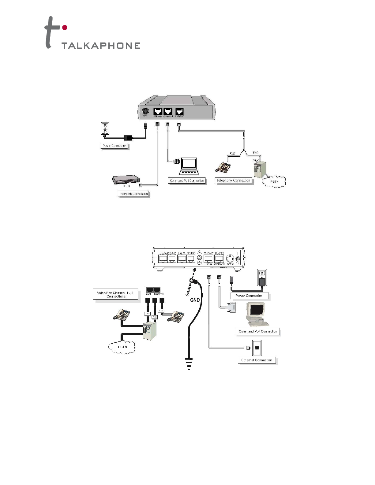
Hookup for VOIP-1
Figure 1-9: Sample hookup diagram for VOIP-1 Interface Unit
Hookup for VOIP-2
Figure 1-10: Sample hookup diagram for VOIP-2 Interface Unit
CH1
CH2
Page 11
VOICE OVER IP INTERFACE
Installation and Operation Manual
11
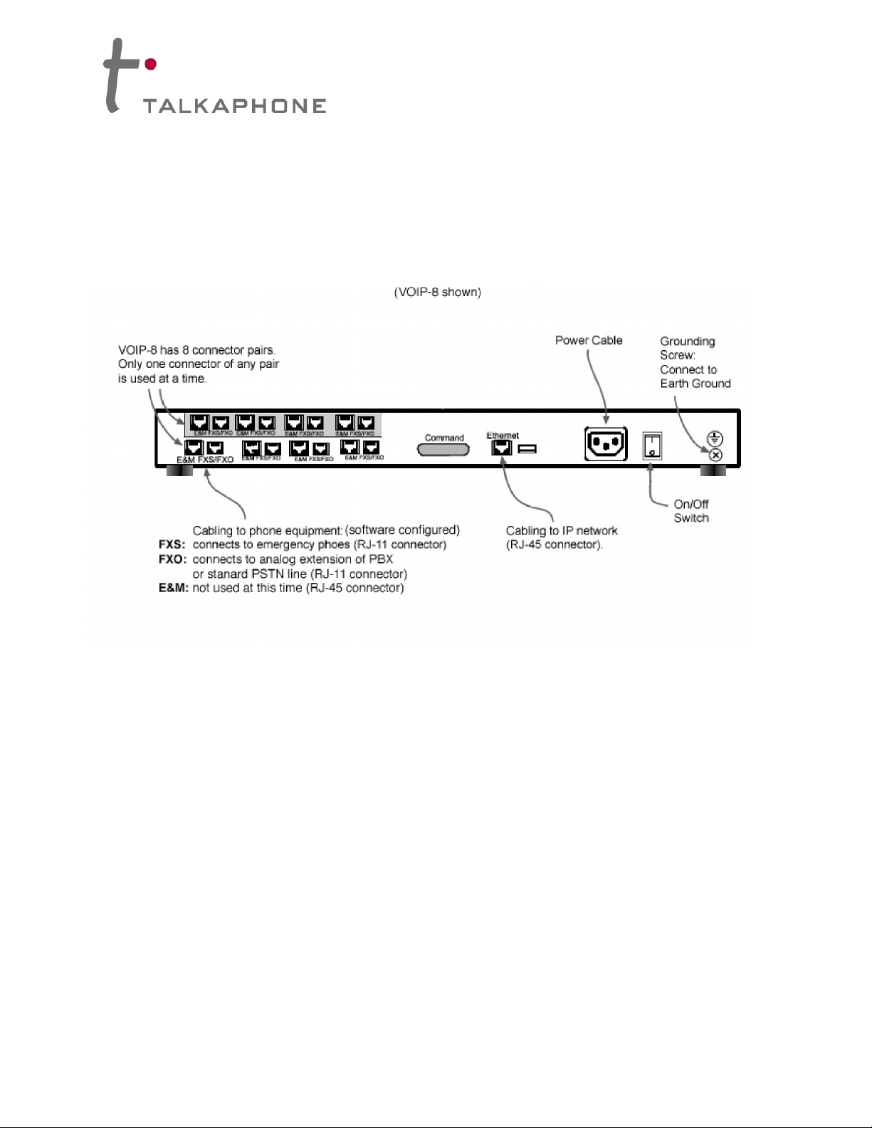
Hookup for VOIP-4 and VOIP-8
Connect the VOIP-4 or VOIP-8 as indicated in the following diagram. Connect the RJ-11 cables from the
emergency phone(s), PSTN line(s), or analog extension(s) of the PBX to the ports labeled “FXS/FXO”.
Make sure to connect the chassis to Earth Ground at the grounding screw as indicated (VOIP-2, VOIP-4,
and VOIP-8 only)
Figure 1-11: Sample hookup diagram for VOIP-4/VOIP-8 Interface Unit
Operation
When the VOIP unit is powered on, it will take approximately one minute to boot up. The red LED
(second from the left) indicates that the unit is still booting. After the red LED clears, allow an extra
twenty seconds to ensure the unit has fully booted before attempting to initiate a call.
The emergency phones will need to be programmed in accordance with the instructions in the Quick
Start section in Chapter 2.
Page 12
VOICE OVER IP INTERFACE
Installation and Operation Manual
12
VoIP System Design
Before you begin programming the VOIP Interface units, it is recommended that you plan out your system
layout. You should begin by choosing a setup type. There are two basic types of VoIP setups we can
design for an emergency phone system:
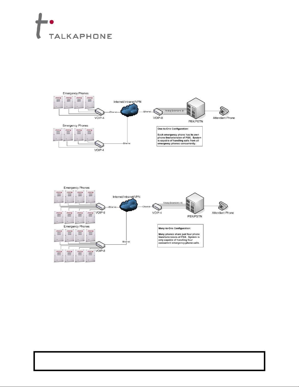
Figure 1-12: One-to-One Configuration
(1) The first setup type is a one-to-one configuration. In this scenario, each emergency phone has
its own PBX extension or phone line. The number of calls that the head end is capable of receiving
is equal to the number of emergency phones in the field.
Figure 1-13: Many-to-One Configuration
(2) The second setup type is a many-to-one configuration. In this scenario, many Emergency Phones
share PBX extensions or phone lines. The number of calls that the head end is capable of receiving is
less than the number of emergency phones in the field.
Once you have chosen a setup type, it is recommended that you assign phone numbers/PBX extensions
to the emergency phones and IP addresses to the VOIP units before programming any of the VOIP units.
Keep in mind that the PBX extension assignments are separate from the VOIP phone book extensions.
Please reference Phone Book Design (p. 18) for more information.
When designing your system layout, please keep in mind that All VOIP units must have fixed IP
addresses. Also, ensure that the proper routing and switching hardware (routers, hubs, firewalls, VPNs,
etc.) are in place for the VOIP units to communicate. It is critical that ensure network reliability, which
includes sufficient bandwidth and minimizes packet loss and packet delays.
IMPORTANT NOTE: For the Emergency Phone System to work through a power outage, all components of
the data path (i.e. the VOIP units, routers, hubs, switches, etc.) must be on back-up power.
Page 13
VOICE OVER IP INTERFACE
Installation and Operation Manual
13
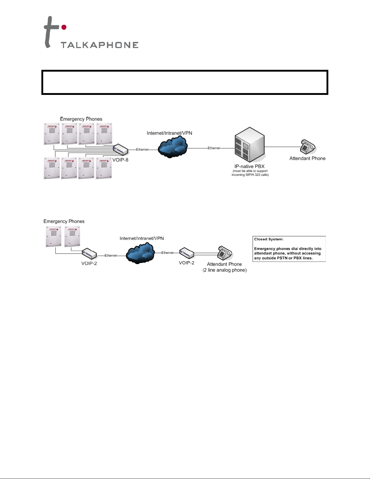
The following are examples of other types of VoIP setups you can design.
Figure 1-14: Many-to-One IP-Native Head End Configuration
(3) Figure 1-14 is an example of a configuration with a completely IP-native head end. With the IP-native
PBX, there isn’t a need for VOIP units at the head end.
Figure 1-15: One-to-One Closed Configuration
(4) Figure 1-15 is an example of a closed configuration with no PBX or PSTN lines. This configuration
type relies solely on the network infrastructure for call routing.
IMPORTANT NOTE: For the Emergency Phone System to work through a power outage, all components of
the data path (i.e. the VOIP units, routers, hubs, switches, etc.) must be on back-up power.
Page 14

VOICE OVER IP INTERFACE
Installation and Operation Manual
14
CHAPTER 2:
Quick Start Guide for VOIP-1-2-4-8 Units
Download VOIP-1-2-4-8 Configuration Software
You can download the configuration and firmware update utility by following one of the links below or by
going to the product page at www.talkaphone.com/products/
VOIP-1: www.talkaphone.com/sites/default/files/software/VOIP-1-2-4-8/voip-1.zip
VOIP-2-4-8: www.talkaphone.com/sites/default/files/software/VOIP-1-2-4-8/voip-2-4-8.zip
Install VOIP-1-2-4-8 Configuration Software onto a PC
1. VOIP-1-2-4-8 must be properly cabled. Power must be turned on.
2. Extract the content of either “voip-1.zip” or “voip-2-4-8.zip” depending on the model used.
Open the extracted folder and double-click on the autorun.exe icon.
3. At first dialog box, click on Install Software.
4. If you will be configuring the VOIP unit remotely from the network and the PC does not have
the Java Runtime Environment installed, highlight Java and click OK. Otherwise, skip to
Step (7).
5. Follow the on-screen instructions to properly install the Java Runtime Environment.
6. Click on Install Software under the autorun.exe that was launched in Step (2).
7. Highlight either VOIP-1 Software or VOIP-2-4-8 Software and click OK.
8. At the “Welcome” screen, click Next.
9. Follow on-screen instructions. Accept default program folder location and click Next.
10. Accept default icon folder location. Click Next. Files will be copied.
11. At completion screen, click Finish.
12. At the prompt “Do you want to run VOIP-1-2-4-8 Configuration?,” click No. Software
installation is complete.
13. Go to Start ! All Programs ! VOIP-1 or VOIP-2-4-8 ! Configuration Port Setup. Select
the proper COM port that will be used to configure the VOIP unit.
Notes on the Configuration of VOIP-1-2-4-8 Units
The initial configuration of the VOIP-1-2-4-8 units must be done locally using the Windows GUI.
However, all additional configurations can be done via the Web GUI once you know the IP address of the
VOIP unit being configured. The VOIP-1-2-4-8 unit can be reprogrammed remotely in almost every setup
where a computer can access the web interface GUI.
Once you have finished programming the VOIP units, you may set each of the units to request a login
and password each time the configuration software is launched. For more information on this topic,
please reference Setting a Password (pp. 38-39).
IMPORTANT NOTE: After each configuration change, make sure to hit OKAY at each screen. Once you have
completed configuring all options, make sure to also “Save Settings and Reboot”. If you do not click save and
reboot, all changes will be lost.
Page 15

VOICE OVER IP INTERFACE
Installation and Operation Manual
15
Phone/IP Starter Configuration
The following are steps that Talk-A-Phone Co. recommends that you take in order to create a functional
VoIP system.
1. Open the VOIP-1-2-4-8 configuration program: Start | Programs | VOIP-x-x-x | Configuration.
2. Configuring the IP address. Go to Configuration | IP. Enter the IP parameters for your VoIP
site. Leave “Enable DHCP” unchecked unless your network setup requires DHCP.
NOTE: If a phone’s IP is established via DHCP, it can only make outgoing calls, not ingoing call,
unless it is set up to register with an H.323 gatekeeper, SIP proxy, or SPP master VOIP. Also,
your VoIP until must also specify a Gateway address in order for it to work properly even if a
Gateway will never be used.
If you will be using the VOIP-1-2-4-8 unit on an existing network, please consult your
network administrator for IP addresses, subnet mask, and gateway information. If you will
be creating a dedicated network, you may use proper private addressing (e.g. IP address
192.168.1.25, subnet mask 255.255.255.0, and a gateway 192.168.1.1).
3. If you would like to configure and operate the VOIP-1-2-4-8 unit using the web browser GUI,
continue on to step (4). The Web GUI has the same functionality as the local Windows GUI, but
offers remote access. If you would like to continue with the Windows GUI, skip to step (5).
4. Enable Web browser GUI (Optional). To do configuration and operation procedures using the
web browser GUI, you must first enable it. Once you’ve begun using the web browser GUI, you
can go back to the Windows GUI at any time. However, you must log out of the web browser GUI
before using the Windows GUI. To do so, follow these steps:
a. Close the Windows GUI.
b. Make sure Java Runtime Environment 1.4.2_01 or greater is installed.
c. Launch a compatible web browser (Internet Explorer 6.0 or above; or Netscape 6.0 or
above).
d. IMPORTANT NOTE: The PC being used must be connected to and have an IP address
on the same
e. IP network of the VOIP unit.
f. Browse to IP address of the VOIP unit being configured.
g. If a username and password have been established, enter them when prompted.
h. Use web browser GUI to configure VOIP unit.
5. Go to Configuration | Voice/Fax. Select Coder | “Manual.” Choose “G.711 u-law @ 64kbps” as
the Selected Coder from the pulldown menu. Talkaphone recommends G.711 u-law for
maximum line quality. It is especially recommended that this coder be selected when Talk-A-Lert
will be used with VoIP.
Under DTMF, select “Inband” from the DTMF pulldown menu.
IMPORTANT NOTE: After each configuration change, make sure to hit OKAY at each screen. Once you have
completed configuring all options, make sure to also “Save Settings and Reboot”. If you do not click save and
reboot, all changes will be lost.
Page 16

VOICE OVER IP INTERFACE
Installation and Operation Manual
16
Under Advanced Features, make sure that Silence Compression is “unchecked”.
Under Automatic Disconnection, set the Call Duration to “3600” secs.
For VoIP units connected to emergency phones in a many-to-one configuration or for one-to-one
configurations (For more information on many/one-to-one configurations, see VoIP System
Design p. 12), it is recommended that you enable the Auto Call feature.
The Auto Call feature automatically links the emergency phone to the dial tone of the PBX
extension or phone line, so the emergency phone only needs to dial the extension or phone
number to reach the attendant at the head end.
Under Auto Call/OffHook Alert, select “Auto Call” from the pulldown menu and specify the
Phone Number that you would like the emergency phone to dial. Please reference Phone Book
Design (p. 18) for clarification on the phone number you should enter in this field. For head end
units of a many-to-one configuration, select “None” under Auto Call/OffHook Alert.
If you know of any other specific parameter values that will apply to your system, enter them.
Most of the time, all the channels on the multi-channel VOIP units will share the same parameter
values. To facilitate settings duplication, you can copy parameter settings from one channel to
another. Click Copy Channel. Select Copy to All. Click Copy. At the main Voice/Fax
Parameters screen, click OK to exit from the dialog box.
6. Go to Configuration | Interface. Select Interface Type | “FXS” if connecting to emergency
phones or for head end of “closed system” (ringing phone directly off head end VOIP unit without
any external phone lines or PBX), “FXO” for head end VOIP unit(s) (connecting to PBX
extensions or analog phone lines).
If the VoIP unit will be using an “FXS” interface, make sure that FXS Options | Current Loss is
“checked”. This will allow the emergency phone to hang up automatically when a call is over.
Go to Disconnect on Call Progress Tone and make sure that it is “checked”.
Under Flash Hook Options, set the Detection Range to a minimum of “100” ms and a maximum
of “150” ms.
If you know of any other specific parameter values that will apply to your system, enter them.
Most of the time, all the channels on the multi-channel VOIP units will share the same parameter
values. To facilitate settings duplication, you can copy parameter settings from one channel to
another. Click Copy Channel. Select Copy to All. Click Copy. At the main Voice/Fax
Parameters screen, click OK to exit from the dialog box.
7. Go to Configuration | Regional Parameters. Select Custom from the Country/Region
pulldown menu. Now change the entries for the following types:
Unobtainable Tone: Survivability Tone:
Frequency 1 = 480 Frequency 1 = 480
Frequency 2 = 620 Frequency 2 = 620
Cadence 1, 2, 3, 4 = 500 Cadence 1, 2, 3, 4 = 500
Reorder Tone:
Frequency 1, 2 = 999
Cadence 1, 2, 3, 4 = 0
Page 17

VOICE OVER IP INTERFACE
Installation and Operation Manual
17
These settings should be similar to that for USA except for the above changes.
Click OK to exit from the Regional Parameters dialog box.
8. SMTP Configuration. You can configure the VOIP units to send e-mail notifications. If you
would like to receive phone-call logs from the VOIP-1-2-4-8 via e-mail (to your VoIP Administrator
or someone else), continue with step (9). If not, skip to step (10).
9. Go to Configuration | SMTP. SMTP allows you to send phone-call log records to the VoIP
Administrator via e-mail. Check Enable SMTP. You should have already obtained an e-mail
address for the VOIP-1-2-4-8 unit itself (this serves as the origination e-mail account for e-mail
logs that the VOIP-1-2-4-8 can e-mail out automatically).
Enter this e-mail address in the “Login Name” field. Type the password for this e-mail account.
Enter the IP \address of the e-mail server where the VOIP-1-2-4-8’s e-mail account is located in
the “Mail Server IP Address” field.
Typically the e-mail log reports are sent to the VoIP Administrator but they can be sent to any email address.
Decide where you want the e-mail logs sent and enter that e-mail address in the “Recipient
Address” field. Whenever e-mail log messages are sent out, they must have a standard Subject
line (e.g. “Phone Logs for VoIP N”). If you have more than one VOIP-1-2-4-8 unit in the building,
you’ll need a unique identifier for each one (select a useful name or number for “N”). In this
“Subject” field, enter a useful subject title for the log messages.
In the “Reply-To Address” field, enter the e-mail address of your VoIP Administrator.
10. Go to Configuration | Logs. Select “Enable Console Messages.” To allow log reports by e-mail
(if desired), click SMTP. Click OK. To do logging with a SysLog client program, check Enable
under “SysLog Server” in the Logs screen and specify the SysLog Server’s IP Address. To
implement this function, you must install a SysLog client program.
11. Enable premium (H.450) telephony features. Go to Configuration | Supplementary
Services. Select any features to be used. For Call Hold, Call Transfer, and Call Waiting, specify
the key sequence that the phone user will press to invoke the feature. For Call Name
Identification, specify the allowed name types to be used and a caller-id descriptor.
If Call Forwarding is to be used, enable this feature in the Add/Edit Inbound Phone Book screen.
12. Naming the VoIP gateway. Go to Phone Book | Phone Book Configuration. Enter the name
you would like the VOIP unit to use. This name will be used when the Caller ID feature is
enabled.
13. Programming outbound phone book information. Go to Phone Book | Outbound Phone
Book | List Entries. Click on Add to create new entries. The Outbound phone book lists the
phone numbers or extensions the VOIP unit can call. Please reference the Phone Book Design
section (p. 18) for information and examples on how to program the phone book.
14. Programming inbound phone book information. Go to Phone Book | Inbound Phone Book
| List Entries. Click on Add to create new entries. The Inbound phone book describes the
dialing sequences that can be used to call the VOIP unit being programmed unit and how those
Page 18

VOICE OVER IP INTERFACE
Installation and Operation Manual
18
calls will be directed. Please reference the Phone Book Design section (p. 18) for information
and examples on how to program the phone book.
15. Changing user name and password (Web GUI only. See p. 38 for instructions on the
Windows GUI). Go to Change Password. Specify the User Name that you would like to use
for this VOIP unit.
If an Old Password exists, enter that password. Now proceed with assigning a New Password
and then Reconfirm Password.
16. Save configuration changes. Go to Save Setup | Save and Reboot. Click OK. This will save
the parameter values that you have just entered. The VOIP-1-2-4-8’s “BOOT” LED will light up
while the configuration file is being saved and loaded into the VOIP-1-2-4-8. Don’t do anything to
the VOIP-1-2-4-8 until the “BOOT” LED is off (a loss of power at this point could cause the VOIP1-2-4-8 unit to lose the configuration settings you have made).
Page 19

VOICE OVER IP INTERFACE
Installation and Operation Manual
19
Phone Book Design
Phone book entries are critical when designing a VoIP setup for Emergency Phones. The phone book in
the VOIP units serve in providing routing information for calls over a Voice-over IP setup. The Outbound
phone book for a particular VOIP unit describes the dialing sequences required for a call to originate
locally and reach any of its possible destinations at remote VoIP sites. The Inbound phone book for a
particular VoIP unit describes the dialing sequences required for a call to originate remotely from any
other VOIP sites in the system, and to terminate on that particular VOIP.
Concisely, the Outbound phone book lists the phone stations it can call and the Inbound phone book
describes the dialing sequences that can be used to call that VOIP unit and how those calls will be
directed. In general, the Inbound phone book entries of the local VOIP unit will match the Outbound
phone book entries of the remote VOIP unit. Similarly, the Outbound phone book entries of the local
VOIP unit will match the Inbound phone book entries of the remote VOIP unit. However, in most cases,
the VOIP units will only have some matching entries.
Once you’ve programmed the VOIP units with a known IP address, you can remotely program the phone
books of each unit through the Web GUI. The following steps will assist you in completing the task of
programming the phone book(s).
1. Open a web browser to the VOIP-1-2-4-8 to be configured to access the Web GUI. Go to
Phone Book.
2. Under Outbound Phone Book, add entries for the extensions and IP addresses for each
emergency phone or extension/phone number that the VOIP unit will call. It is advised that
every entry be configured for the H.323 protocol.
To add an entry, click on Add. Enter the extension/phone number to be dialed in the
Destination Pattern field. Specify the Total Digits and the IP Address to which that
number is assigned.
You can now continue configuring other parameters such as SIP proxy and H.323 gateway
information. Click OK once you have completed configuring this entry. You should repeat
step (2) for all outbound phone book entries.
3. Under Inbound Phone Book, add entries for the dialing sequences that can be used to call
the VOIP unit being configured.
To add an entry, click on Add. Enter the extension/phone number to be dialed in the
Remove Prefix field. Under Channel Number, make sure that it is not set for “Hunting”
mode. Assign a Channel Number to each extension/phone number to a port on the multi-
channel VOIP units (VOIP-2, VOIP-4, VOIP-8).
You can now continue configuring other parameters such as Call Forward. Click OK once
you have completed configuring this entry. You should repeat step (3) for all inbound phone
book entries.
Page 20

VOICE OVER IP INTERFACE
Installation and Operation Manual
20
Phone Book Design Example 1
In Figure 2-1, we have a one-to-one configuration. Each emergency phone will have an assigned
PBX extension, so the head end VOIP-4 will only be using three of its four channels. Also, in this
scenario, the PBX is set to ringdown mode, so every emergency phone is programmed with *13*5*
and each VOIP unit connected to an emergency phone is configured to auto call/hotline to the
attendant phone.
Figure 2-1: Example of a one-to-one VoIP System Configuration
For the VOIP units connected to emergency phones, we would program the phone books with the
following information.
Emergency Phone 1:
Inbound Phone Book entry: 101
Outbound Phone Book entry: 201 assigned to 192.168.37.40
Emergency Phone 2:
Inbound Phone Book entry: 102
Outbound Phone Book entry: 202 assigned to 192.168.37.40
Page 21

VOICE OVER IP INTERFACE
Installation and Operation Manual
21
Emergency Phone 3:
Inbound Phone Book entry: 103
Outbound Phone Book entry: 203 assigned to 192.168.37.40
In this scenario, each emergency phone VOIP unit has been programmed to call one specific
extension at the head end. There is no need to assign a channel to the inbound phone book entry
because there exists only one channel for these VOIP units.
If we look at the phone book for the head end VOIP unit connected to the Attendant Phone, it should
be programmed with:
Attendant Phone:
Inbound Phone Book entries: 201 assigned to Channel 1
202 assigned to Channel 2
203 assigned to Channel 3
Outbound Phone Book entries: 101 assigned to 192.168.37.10
102 assigned to 192.168.37.20
103 assigned to 192.168.37.30
In this case, each PBX extension has been assigned a number (201, 202, and 203). Thus, when
Emergency Phone 2 places a call, it will connect to extension 202 by routing to Channel 2 on the
head end VOIP unit. The attendant also has the ability to call into each of the emergency phones by
dialing 101, 102, or 103 for the respective phones.
Page 22

VOICE OVER IP INTERFACE
Installation and Operation Manual
22
Phone Book Design Example 2
Let us look at another example:
Figure 2-2: Example of a many-to-one VoIP System Configuration
In this scenario, we have a many-to-one closed system. This setup does not make use of a PBX or
PSTN lines. The system has been designed so that Emergency Phones 1 and 2 will share line 201 and
Emergency Phones 3 and 4 will share line 202. The emergency phones should have been properly
programmed so that if a busy signal is received, the emergency phone will try to dial the same number or
it will dial an alternate number.
If we look at the phone book configuration for the VOIP-2 unit connected to Emergency Phones 1
and 2, we will find the following:
Inbound Phone Book entry: 101 assigned to Channel 1
102 assigned to Channel 2
Outbound Phone Book entry: 201 assigned to 192.168.37.3
Similar programming goes for the VOIP-2 unit connected to Emergency Phones 3 and 4.
If we look at the phone book configuration for the head end VOIP unit connected to the Attendant
Phone, it should be programmed with:
Attendant Phone:
Inbound Phone Book entries: 201 assigned to Channel 1
202 assigned to Channel 2
Outbound Phone Book entries: 101 assigned to 192.168.37.1
Page 23

VOICE OVER IP INTERFACE
Installation and Operation Manual
23
102 assigned to 192.168.37.1
103 assigned to 192.168.37.2
104 assigned to 192.168.37.2
In this case, the attendant phone has been assigned 201 and 202 and their extensions. So, when
Emergency Phone 2 places a call, it will connect to extension 201 by routing to Channel 1 on the
head end VOIP unit.
The attendant also has the ability to call into each of the emergency phones by dialing 101, 102,
103, or 104 for the respective phones. What happens when the attendant calls Emergency Phone 2
from line 1 (extension 201)? The call is routed from Channel 1 on the head end VOIP unit, through
the LAN, to Channel 2 on the VOIP unit connected to Emergency Phone 2.
Page 24

VOICE OVER IP INTERFACE
Installation and Operation Manual
24
Operation and Maintenance
Although most Operation and Maintenance functions of the software are in the Statistics group of
screens, an important summary appears in the System Information of the Configuration screen group.
System Information screen
This screen presents vital system information at a glance. Its primary use is in troubleshooting. This
screen is accessible via the Configuration pulldown menu, the Configuration sidebar menu, or by the
keyboard shortcut Ctrl + Alt + Y.
Field Name
Values
Description
Boot Version
nn.nn
Indicates the version of the code that is used at
the startup (booting) of the VoIP unit. The boot
code version is independent of the software
version.
MAC Address
alphanumeric
Denotes the number assigned as the VoIP
unit’s unique Ethernet address.
Up Time
days: hours:
mm:ss
Indicates how long the VoIP unit has been
running since its last booting.
Firmware
Version
alphanumeric
Indicates the version of the firmware.
The frequency with which the System Information screen is updated is determined by a setting in the
Logs screen.
Statistics Screens
Ongoing operation of the VOIP-1-2-4-8, whether it is in a VoIP/PBX setting or VoIP/telco-office setting,
can be monitored for performance using the Statistics functions of the VOIP-1-2-4-8 software.
Page 25

VOICE OVER IP INTERFACE
Installation and Operation Manual
25
About Call Progress
Call Progress Details: Field Definitions
Field Name
Values
Description
Channel
1-n
Number of data channel or time
slot on which the call is carried.
This is the channel for which callprogress details are being viewed.
Call Details
Duration
Hours:
Minutes:
Seconds
The length of the call in hours,
minutes, and seconds (hh:mm:ss).
Mode
Voice or FAX
Indicates whether the call being
described was a voice call or a
FAX call.
Voice Coder
G.723, G.729,
G.711, etc.
The voice coder being used on
this call.
Packets Sent
integer value
The number of data packets sent
over the IP network in the course
of this call.
Packets Rcvd
integer value
The number of data packets
received over the IP network in
the course of this call.
Bytes Sent
integer value
The number of bytes of data sent
over the IP network in the course
of this call.
Bytes Rcvd
integer value
The number of bytes of data
received over the IP network in
the course of this call.
Packets Lost
integer value
The number of voice packets from
this call that were lost after being
received from the IP network.
Outbound
Digits
0-9, #, *
The digits transmitted by the
VOIP-1-2-4-8 to the PBX/telco for
this call.
Prefix
Matched
Displays the dialed digits that
were matched to a phonebook
entry.
Page 26

VOICE OVER IP INTERFACE
Installation and Operation Manual
26
Call Progress Details: Field Definitions (cont’d)
From – To Details
Description
Gateway
Name
alphanumeric
string
Identifier for the VOIP gateway
that handled this call.
IP Address
x.x.x.x, where
x has a range
of 0 to 255
IP address from which the call
was received.
Options
SC, FEC
Displays VOIP transmission
options in use on the current call.
These may include Forward Error
Correction or Silence
Compression.
Silence
Compression
SC
“SC” stands for Silence
Compression. With Silence
Compression enabled, the VOIP1-2-4-8 will not transmit voice
packets when silence is detected,
thereby reducing the amount of
network bandwidth that is being
used by the voice channel.
Forward Error
Correction
FEC
“FEC” stands for Forward Error
Correction. Forward Error
Correction enables some of the
voice packets that were corrupted
or lost to be recovered. FEC adds
an additional 50% overhead to the
total network bandwidth
consumed by the voice channel.
Default = Off
Page 27

VOICE OVER IP INTERFACE
Installation and Operation Manual
27
Call Progress Details: Field Definitions (cont’d)
Field Name
Values
Description
Supplementary Services
Status
Call on Hold
alphanumeric
Describes held call by its IP
address source, location/gateway
identifier, and hold duration.
Location/gateway identifiers come
from Gateway Name field in
Phone Book Configuration
screen of remote VOIP.
Call Waiting
alphanumeric
Describes waiting call by its IP
address source, location/gateway
identifier, and hold duration.
Location/gateway identifiers come
from Gateway Name field in
Phone Book Configuration
screen of remote VOIP.
Page 28

VOICE OVER IP INTERFACE
Installation and Operation Manual
28
Call Progress Details: Field Definitions (cont’d)
Field Name
Values
Description
Supplementary Services
Status
Caller ID
There are four
values:
“Calling Party
+ identifier”;
“Alerting Party
+ identifier”;
“Busy Party +
identifier”; and
“Connected
Party +
identifier”
This field shows the identifier and
status of a remote VOIP (which
has Call Name Identification
enabled) with which this VOIP unit
is currently engaged in some
VOIP transmission. The status of
the engagement (Connected,
Alerting, Busy, or Calling) is
followed by the identifier of a
specific channel of a remote VOIP
unit. This identifier comes from the
“Caller Id” field in the
Supplementary Services screen
of the remote VOIP unit.
Status
hangup, active
Shows condition of current call.
Call Control
Status
Tun, FS + Tun,
AE, Mux
Displays the H.323 version 4
features in use for the selected
call. These include tunneling
(Tun), Fast Start with tunneling
(FS + Tun), Annex E multiplexed
UDP call signaling transport (AE),
and Q.931 Multiplexing (Mux).
See Phonebook Configuration
Parameters (in T1 or E1
chapters) for more on H.323v4
features.
Page 29

VOICE OVER IP INTERFACE
Installation and Operation Manual
29
About Logs
Logs Screen Details: Field Definitions
Field Name
Values
Description
Event # column
1 or higher
All calls are assigned an event
number in chronological order,
with the most recent call having
the highest event number.
Start Date,Time
column
dd:mm:yyyy
hh:mm:ss
The starting time of the call
(event). The date is presented as
a day expression of one or two
digits, a month expression of one
or two digits, and a four-digit
year. This is followed by a timeof-day expression presented as a
two-digit hour, a two-digit minute,
and a two-digit seconds value.
(statistics, logs) field
Duration column
hh:mm:ss
This describes how long the call
(event) lasted in hours, minutes,
and seconds.
Status column
success or
failure
Displays the status of the call,
i.e., whether the call was
completed successfully or not.
Mode column
voice or FAX
Indicates whether the (event)
being described was a voice call
or a FAX call.
From column
gateway name
Displays the name of the voice
gateway that originates the call.
To column
gateway name
Displays the name of the voice
gateway that completes the call.
Special Buttons
Last Displays last log entry.
Delete File
Deletes selected log file.
Call Details
Packets sent
integer value
The number of data packets sent
over the IP network in the course
of this call.
Bytes sent
integer value
The number of bytes of data sent
over the IP network in the course
of this call.
Page 30

VOICE OVER IP INTERFACE
Installation and Operation Manual
30
Logs Screen Details: Field Definitions (cont’d)
Field Name
Values
Description
Call Details (cont’d)
Packets loss
(lost)
integer value
The number of voice packets
from this call that were lost after
being received from the IP
network.
Voice coder
G.723, G.729,
G.711, etc.
The voice coder being used on
this call.
Packets received
integer value
The number of data packets
received over the IP network in
the course of this call.
Bytes received
integer value
The number of bytes of data
received over the IP network in
the course of this call.
Outbound digits
0-9, #, *
The digits transmitted by the
VOIP-1-2-4-8 to the PBX/telco
for this call.
FROM Details
Gateway Name
alphanumeric
string
Identifier for the VOIP gateway
that originated this call.
IP Address
x.x.x.x, where x
has a range of 0
to 255
IP address of the VOIP gateway
from which the call was
received.
Options
FEC, SC
Displays VOIP transmission
options used by the VOIP
gateway originating the call.
These may include Forward
Error Correction or Silence
Compression.
TO Details
Gateway Name
alphanumeric
string
Identifier for the VOIP gateway
that completed (terminated) this
call.
IP Address
x.x.x.x, where x
has a range of 0
to 255
IP address of the VOIP gateway
at which the call was completed
(terminated).
Options
Displays VOIP transmission
options used by the VOIP
gateway terminating the call.
These may include Forward
Error Correction or Silence
Compression.
Page 31

VOICE OVER IP INTERFACE
Installation and Operation Manual
31
Logs Screen Details: Field Definitions (cont’d)
Supplementary Services Info (Not
supported in BRI 502c software.)
Call Transferred To
phone number
string
Number of party called in transfer.
Call Forwarded To
phone number
string
Number of party called in
forwarding.
CT Ph#
phone number
string
Call Transfer phone number.
About IP Statistics
IP Statistics: Field Definitions
Field Name
Values
Description
UDP versus TCP. (User Datagram Protocol
versus Transmission Control Protocol). UDP
provides unguaranteed, connectionless
transmission of data across an IP network. By
contrast, TCP provides reliable, connectionoriented transmission of data. Both TCP and
UDP split data into packets called “datagrams.”
However, TCP includes extra headers in the
datagram to enable retransmission of lost
packets and reassembly of packets into their
correct order if they arrive out of order. UDP
does not provide this. Lost UDP packets are
irretrievable; that is, out-of-order UDP packets
cannot be reconstituted in their proper order.
Despite these obvious disadvantages, UDP
packets can be transmitted much faster than
TCP packets -- as much as three times faster.
In certain applications, like audio and video data
transmission, the need for high speed
outweighs the need for verified data integrity.
Sound or pictures often remain intelligible
despite a certain amount of lost or disordered
data packets (which appear as static).
“Clear” button
Clears packet tallies from memory.
Total Packets
Sum of data packets of all types.
Transmitted
integer
value
Total number of packets transmitted by this
VOIP gateway since the last “clearing” or
resetting of the counter within the VOIP
Interface software.
Received
integer
value
Total number of packets received by this VOIP
gateway since the last “clearing” or resetting of
the counter within the VOIP Interface software.
Page 32

VOICE OVER IP INTERFACE
Installation and Operation Manual
32
IP Statistics: Field Definitions (cont’d)
Field Name
Values
Description
Total Packets (cont’d)
Sum of data packets of all types.
Received with
Errors
integer
value
Total number of error-laden packets
received by this VOIP gateway since
the last “clearing” or resetting of the
counter within the VOIP Interface
software.
UDP Packets
User Datagram Protocol packets.
Transmitted
integer
value
Number of UDP packets transmitted by
this VOIP gateway since the last
“clearing” or resetting of the counter
within the VOIP Interface software.
Received
integer
value
Number of UDP packets received by
this VOIP gateway since the last
“clearing” or resetting of the counter
within the VOIP Interface software.
Received with
Errors
integer
value
Number of error-laden UDP packets
received by this VOIP gateway since
the last “clearing” or resetting of the
counter within the VOIP Interface
software.
TCP Packets
Transmission Control Protocol packets.
Transmitted
integer
value
Number of TCP packets transmitted by
this VOIP gateway since the last
“clearing” or resetting of the counter
within the VOIP Interface software.
Received
integer
value
Number of TCP packets received by
this VOIP gateway since the last
“clearing” or resetting of the counter
within the VOIP Interface software.
Received with
Errors
integer
value
Number of error-laden TCP packets
received by this VOIP gateway since
the last “clearing” or resetting of the
counter within the VOIP Interface
software.
Page 33

VOICE OVER IP INTERFACE
Installation and Operation Manual
33
IP Statistics: Field Definitions (cont’d)
RTP Packets
Voice signals are transmitted in
Realtime Transport Protocol packets.
RTP packets are a type or subset of
UDP packets.
Transmitted
integer
value
Number of RTP packets transmitted by
this VOIP gateway since the last
“clearing” or resetting of the counter
within the VOIP Interface software.
Received
integer
value
Number of RTP packets received by
this VOIP gateway since the last
“clearing” or resetting of the counter
within the VOIP Interface software.
Received with
Errors
integer
value
Number of error-laden RTP packets
received by this VOIP gateway since
the last “clearing” or resetting of the
counter within the VOIP Interface
software.
RTCP Packets
Realtime Transport Control Protocol
packets convey control information to
assist in the transmission of RTP
(voice) packets. RTCP packets are a
type or subset of UDP packets.
Transmitted
integer
value
Number of RTCP packets transmitted
by this VOIP gateway since the last
“clearing” or resetting of the counter
within the VOIP Interface software.
Received
integer
value
Number of RTCP packets received by
this VOIP gateway since the last
“clearing” or resetting of the counter
within the VOIP Interface software.
Received with
Errors
integer
value
Number of error-laden RTCP packets
received by this VOIP gateway since
the last “clearing” or resetting of the
counter within the VOIP Interface
software.
Page 34

VOICE OVER IP INTERFACE
Installation and Operation Manual
34
About Link Management
The Link Management screen is essentially an automated utility for pinging endpoints on your VoIP
network. This utility generates pings of variable sizes at variable intervals and records the response to
the pings.
Link Management screen Field Definitions
Field Name
Values
Description
Monitor Link fields
IP Address to
Ping
a.b.c.d 0-255
This is the IP address of the target
endpoint to be pinged.
No. of Pings
1-999
This field determines how many
pings will be generated by the
Start Now command.
Response
Timeout
500 – 5000
milliseconds
The duration after which a ping
will be considered to have failed.
Ping Size in
Bytes
32 – 128 bytes
This field determines how long or
large the ping will be.
Timer Interval
between
Pings
0 or 30 – 6000
minutes
This field determines how long of
a wait there is between one ping
and the next.
Start Now
command
button
Initiates pinging.
Clear
command
button
Erases ping parameters in Monitor
Link field group and restores
default values.
Page 35

VOICE OVER IP INTERFACE
Installation and Operation Manual
35
Link Management screen Field Definitions (cont’d)
Field Name
Values
Description
Link Status Parameters
These fields summarize the
results of pinging.
IP Address
column
a.b.c.d 0-255
Target of ping.
No. of Pings Sent
as listed
Number of pings sent to target
endpoint.
No. of Pings
Received
as listed
Number of pings received by
target endpoint.
Round Trip Delay
(Min/Max/ Avg)
as listed, in
milliseconds
Displays how long it took from
time ping was sent to time ping
response was received.
Last Error
as listed
Indicates when last data error
occurred.
About Packetization Time
You can use the Packetization Time screen to specify definite packetization rates for coders selected in
the Voice/FAX Parameters screen (in the “Coder Options” group of fields). The Packetization Time
screen is accessible under the “Advanced” options entry in the sidebar list of the main VOIP software
screen. In dealing with RTP parameters, the Packetization Time screen is closely related to both
Voice/FAX Parameters and to IP Statistics. It is located in the “Advanced” group for ease of use.
Packetization rates can be set separately for each channel. The table below presents the ranges and
increments for packetization rates.
Packetization Ranges and Increments
Coder Types
Range (in Kbps);
{default value}
Increments (in Kbps)
G711, G726, G727
5-120 {5}
5
G723
30-120 {30}
30
G729
10-120 {10}
10
Netcoder
20-120 {20}
20
Once the packetization rate has been set for one channel, it can be copied into other channels.
Page 36

VOICE OVER IP INTERFACE
Installation and Operation Manual
36
About Registered Gateway Details
The Registered Gateway Details screen presents a real-time display of the special operating parameters
of the Single Port Protocol (SPP). These are configured in the Phone Book Configuration screen and in
the Add/Edit Outbound Phone Book screen.
Registered Gateway Details: Field Definitions
Field
Name
Values
Description
Column Headings
Description
alphanumeric
This is a descriptor for a particular VOIP
gateway unit. This descriptor should
generally identify the physical location of
the unit (e.g., city, building, etc.) and
perhaps even its location in an equipment
rack.
IP Address
n.n.n.n, for n =
0-255
The RAS address for the gateway.
Port Port by which the gateway exchanges
H.225 RAS messages with the gatekeeper.
.
Register
Duration
The time remaining in seconds before the
TimeToLive timer expires. If the gateway
fails to reregister within this time, the
endpoint is unregistered.
Status
The current status of the gateway, either
registered or unregistered.
No. of
Entries
The number of gateways currently
registered to the Registrar. This includes all
SPP clients registered and the Registrar
itself.
Details
Count of
Registered
Numbers
If a registered gateway is selected (by
clicking on it in the screen), The "Count of
Registered Numbers" will indicate the
number of registered phone numbers for
the selected gateway. When a client
registers, all of its inbound phonebook's
phone numbers become registered.
List of
Registered
Numbers
Lists all of the registered phone numbers
for the selected gateway.
Page 37

VOICE OVER IP INTERFACE
Installation and Operation Manual
37
Connectivity Test
The procedures Phone/IP Starter Configuration and Phone Book Design must be completed before
you can do this procedure.
1. These connections must be made:
• VOIP-1-2-4-8 to local phone station
or
• VOIP-1-2-4-8 to extension of key phone system
• VOIP-1-2-4-8 to command PC
• VOIP-1-2-4-8 to Internet
2. Inbound Phonebook and Outbound Phonebook must both be set up with at least one entry in
each. These entries must allow for connection between two VoIP units.
3. Console messages must be enabled. (If this has not been done already, go, in the GUI, to
Configuration | Logs and select the “Console Messages” checkbox.
4. You now need to free up the COM port connection (currently being used by the VOIP-1-2-4-8
configuration program) so that the HyperTerminal program can use it. To do this, you can
either (a) click on Connection in the sidebar and select “Disconnect” from the drop-down
box, or (b) close down the configuration program altogether.
5. Open the HyperTerminal program.
6. Use HyperTerminal to receive and record console messages from the VOIP-1-2-4-8 unit. To
do so, set up HyperTerminal as follows (setup shown is for Windows NT 4.0; details will differ
slightly in other MS operating systems):
Figure 2-3: HyperTerminal window
In the upper toolbar of the HyperTerminal screen, click on the Properties button. In the
“Connect To” tab of the Connection Properties dialog box, click on the Configure
button. In the next dialog box, on the “General” tab, set “Maximum Speed” to 115200
bps.
On the “Connection” tab, set connection preferences to:
Data bits: 8
Parity: none
Stop bits: 1
Page 38

VOICE OVER IP INTERFACE
Installation and Operation Manual
38
Click OK twice to exit settings dialog boxes.
7. Make VOIP call on a local phone line accessing PSTN directly or through key system.
8. Read console messages recorded on HyperTerminal.
Console Messages from Originating VOIP. The VoIP unit that originates the call will send
back messages like that shown below.
[00026975] CAS[0] : RX : ABCD = 1, 1, 1, 1,Pstn State[1] TimeStamp : 26975
[00027190] CAS[0] : TX : ABCD = 1, 1, 1, 1
[00027190] PSTN: cas seizure detected on 0
[00027440] CAS[0] : TX : ABCD = 0, 0, 0, 0
[00033290] PSTN:call detected on 0 num=17637175662*
[00033290] H323IF[0]:destAddr = TA:200.2.10.5:1720,NAME:Mounds
View,TEL:17637175662,17637175662
[00033290] H323IF[0]:srcAddr = NAME:New York,TA:200.2.9.20
[00033440] H323IF [0]:cmCallStateProceeding
[00033500] H323[0]: Remote Information (Q931): VOIP-1
[00033565] CAS[0] : TX : ABCD = 1, 1, 1, 1
[00033675] H323IF [0]: MasterSlaveStatus=Slave
[00033675] H323IF[0]:FastStart Setup Not Used
[00033690] CAS[0] : TX : ABCD = 1, 1, 1, 1
[00033755] H323IF[0]: Coder used 'g7231'
[00033810] PSTN:pstn call connected on 0
Console Messages from Terminating VOIP. The VoIP unit connected to the phone where
the call is answered will send back messages like that shown below.
[00170860] H323[0]: New incoming call
[00170860] PSTNIF : Placing call on channel 0 Outbound digit 7175662
[00170885] CAS[0] : TX : ABCD = 1, 1, 1, 1
[00171095] H323IF [0]: MasterSlaveStatus=Master
[00171105] CAS[0] : RX : ABCD = 1, 1, 1, 1,Pstn State[7]
TimeStamp : 171105
[00171105] H323IF[0]: Coder used 'g7231'
[00171110] H323IF[0]:FastStart Setup Not Used
[00171110] H323IF[0]: Already opened the outgoing logical channel
[00171110] H323IF[0]: Coder used 'g7231'
[00171315] CAS[0] : RX : ABCD = 0, 0, 0, 0,Pstn State[9]
TimeStamp : 171315
[00172275] PSTN: dialing digit ended on 0
[00172285] PSTN: pstn proceeding indication on 0
[00172995] CAS[0] : RX : ABCD = 1, 1, 1, 1,Pstn State[12]
TimeStamp : 172995
[00173660] CAS[0] : TX : ABCD = 1, 1, 1, 1
[00173760] PSTN:pstn call connected on 0
9. When you see the following message, end-to-end VoIP connectivity has been achieved.
“PSTN: pstn call connected on X”
where X is the number of the VoIP channel carrying the call.
10. If the HyperTerminal messages do not confirm connectivity, refer to the
Troubleshooting procedure in this manual.
Page 39

VOICE OVER IP INTERFACE
Installation and Operation Manual
39
Setting a Password (Windows GUI)
Talkaphone recommends that a user name and a secure password be assigned to each VOIP unit in
your system configuration.
After a user name has been designated and a password has been set, that password is required to gain
access to the configuration software under both the Windows and Web GUIs. Only one user name and
password can be assigned to a VOIP unit.
Follow these steps to set a user name and password for the VOIP-1-2-4-8 units:
1. Go to Start | Programs | VOIP-x-x-x | Set Password.
2. You will be asked to confirm that you want to set a password, which requires automatic
rebooting of the VOIP unit. Click OK if you are sure you want to set a password.
3. The Password prompt will now appear. If you intend to use the built-in FTP Server function,
enter a user name. A user name is not required to access the Windows GUI, the Web GUI,
or the commands in the Program group menu. Enter your secure password in the New
Password field of the Password screen. Type the same password again in the Confirm
Password field to verify the password you have chosen.
4. Click OK.
5. A message box will appear indicating that a password has been set successfully. After the
password has been set successfully, the VOIP unit will reboot itself (BOOT LED will light up).
6. After the password has been set, the user will be required to enter the password to gain
access to the Web GUI and any of the software components listed in the Program group
menu.
7. Both the User Name and Password are both needed for access to the FTP Server residing in
the VOIP unit. When the Windows GUI asks for the password upon launch of the program, it
will simply quit if CANCEL is selected. The Windows GUI will then produce an error
message if an invalid password is entered.
IMPORTANT NOTE: Record your user name and password in a safe place. If the password is lost, forgotten, or
irretrievable, the user must restore the VOIP-1-2-4-8 to factory defaults.
Page 40

VOICE OVER IP INTERFACE
Installation and Operation Manual
40
Setting a Password (Web GUI)
Setting a password is optional when using the Web GUI. Only one password can be assigned and it
works for all VOIP-1-2-4-8 software functions (Windows GUI, web browser GUI, FTP server, and all
Program menu commands, e.g., Upgrade Software – only the FTP Server function requires a User Name
in addition to the password). After a password has been set, that password is required to access the web
browser GUI.
Figure 2-4: ‘Change Password’ preference pane under Web GUI
IMPORTANT NOTE: Record your user name and password in a safe place. If the password is lost, forgotten, or
irretrievable, the user must restore the VOIP-1-2-4-8 to factory defaults.
Page 41

VOICE OVER IP INTERFACE
Installation and Operation Manual
41
Appendix A:
Troubleshooting the Voice over IP Interfaces
I cannot connect to a VOIP-1-2-4-8 unit remotely via the Web GUI.
1. Check the power and cabling for the VoIP unit.
2. Be sure an IP address has been assigned to the VOIP-1-2-4-8 unit (this must be done in the
Windows GUI).
3. Make sure that the configuration was saved in the Windows GUI. Each pane in the
configuration software requires you to click on “Ok” before you “Save and reboot”.
4. Make sure that the latest version of Java is installed for your browser.
5. Make sure that the PC being used to access the VOIP unit remotely is on the same IP
network.
6. Make sure that a firewall is not blocking traffic the addresses and ports that the VOIP-1-2-4-8
use. Also, check to make sure that any routers in between are configured properly.
I cannot establish connectivity between two VoIPs in the system. I have phones that will not
connect in my setup.
1. Ping both VOIP-1-2-4-8 units to confirm connectivity to the network.
2. Verify the telephone connections. Check cabling. Are connections well seated? To correct
receptacle?
Are telephone Interface Parameter settings correct?
3. Verify phonebook configuration.
4. Observe console messages while placing a call. Look for error messages indicating phonebook
problems, network problems, voice-coder mismatches, etc.
The emergency phone consistently gets a busy signal or it is unable to dial out to the intended
phone.
1. Make sure the voice codecs are the same on all VOIP-1-2-4-8 units.
2. Verify phonebook and ensure that the calls are being routed to the intended box.
3. Make sure that the VOIP-1-2-4-8 unit is configured with a proper gateway address.
Page 42

VOICE OVER IP INTERFACE
Installation and Operation Manual
42
The emergency phone(s) in my setup seem to be experiencing low microphone.
If your setup includes consolidators and an Iwatsu PBX, there might be volume issues where the
microphone volume of the emergency phone is low. Test different GAIN settings to achieve
optimal results, but note that if the gain is too high, the DTMF may become distorted and make
the PBX unable to route the calls. Adjust the voice gain setting to achieve optimal volume. You
may first want to try setting the VOIP-1-2-4-8 field units to:
VOICE GAIN: +5db IN, -5dB OUT
Also, increasing the trim pot on the emergency phones may help.
The attendant phone(s) cannot pick up microphone input from the emergency phone(s) in my
setup.
Ensure that all Emergency Phones are programmed to operate on Mode III.
My configuration changes are not saved in the VOIP unit.
After each configuration change, make sure to hit OKAY at each screen, and do a “save settings
and reboot” when you are done. If you do not click save and reboot, all changes will be lost.
Page 43

VOICE OVER IP INTERFACE
Installation and Operation Manual
43
Appendix B:
Frequently Asked Questions
How far can a phone be from the VOIP-1-2-4-8?
The VoIP Interface units work with 1000 ft. (24AWG) twisted pair copper wire.
Does the VOIP-1-2-4-8 provide power to the phone?
Yes, all of the VoIP Interface units provide power to the Emergency Phones.
My VOIP-1-2-4-8 is taking a long time to boot up. Is this normal?
Yes, the VOIP-1-2-4-8 units typically take about one minute to complete a cold boot.
How do I install a VOIP-1-2-4-8 behind a firewall or Proxy Server?
Your firewall or proxy server will need to support either H.323 or SIP. You may also open up the
ports listed below.
H.323 protocol uses:
UDP: 5000-5075, 16000-20000
TCP: 1720, 16000-20000
Q.931: 900-916
SIP protocol uses:
UDP: 5000-5300
SPP protocol uses:
UDP: 10000 (or the port number specified in the outbound phone book entries)
NOTE: Opening up firewall ports can make your network vulnerable to an attack. Please consult with
your network administrator before carrying out any firewall configuration changes.
 Loading...