

Page 1
INSTALLATION & OPERATION MANUAL
IW-HFM-4
Interview Window Intercom System
with Paging and Music Options
Talk-A-Phone Co. • 7530 North Natchez Avenue • Niles, Illinois 60714-3804 Rev. 7/27/09
Phone 773.539.1100 • Fax 773.539.1241 • info@talkaphone.com • www.talkaphone.com
All prices and specifications are subject to change without notice.
Talk-A-Phone, Talk-A-Lert, Scream Alert and WEBS are registered trademarks of Talk-A-Phone Co.
Copyright 2009 Talk-A-Phone Co. All rights reserved.
Page 2

SYSTEM OVERVIEW
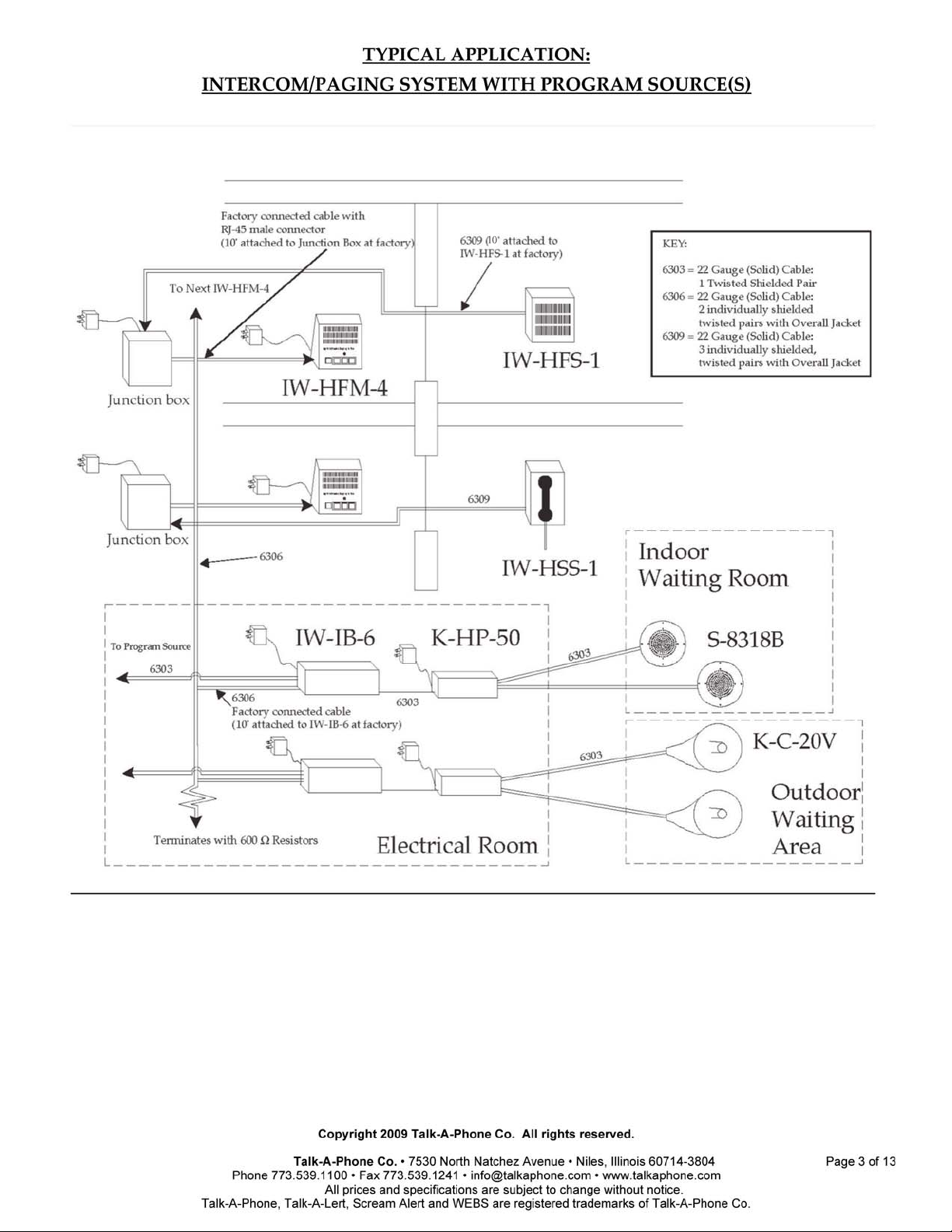
The Interview Window Intercom System is designed for high-quality one-to-one handsfree voice communications and multi-zone paging. It is built to enhance intelligibility
of the human voice through background and outside noises. Installation involves
running one 2-pair cable as a paging bus, and 3-pair cable between a master and its substation.
Speakers, such as outdoor-rated horn speakers or ceiling speakers, may be grouped in
such a way as to create Paging Zones. One Interface Box is used per Zone. Typically, a
Paging Zone consists of 2 or 3 speakers in one room or two nearby rooms. By a simple
dip-switch setting, each master can designate which 2 of up to 6 zones it can page. In
addition, each master can page all zones at once.
Background music or other program material may also be added to the system in such a
way that when one zone is paged, the program source is interrupted in that zone only.
Each zone may have its own program source or zones may share the program material.
This is accomplished by a simple 1-pair connection.
The interviewer can speak to the sub-station in one of three ways: 1) through the builtin microphone in the Master; 2) by speaking into an optional thin gooseneck
microphone; 3) using an optional wireless headset/microphone that allows the
interviewer a free range of movement without interfering with their communication.
Talk-A-Phone Co. • 7530 North Natchez Avenue • Niles, Illinois 60714-3804 Page 2 of 13
Phone 773.539.1100 • Fax 773.539.1241 • info@talkaphone.com • www.talkaphone.com
All prices and specifications are subject to change without notice.
Talk-A-Phone, Talk-A-Lert, Scream Alert and WEBS are registered trademarks of Talk-A-Phone Co.
Copyright 2009 Talk-A-Phone Co. All rights reserved.
Page 3
Page 4
INSTALLATION
Each IW-HFM-4 Interview Window Hands-Free Master has four buttons. Pressing
them will cause the master to communicate with: 1) the sub-station directly in front of
them, 2) the paging speakers in their primary zone, 3) the paging speakers of an
alternate zone, and 4) all paging speakers in the system. In order to make the
appropriate dip-switch settings at each IW-HFM-4 Master, you will have to know the
zone number of each IW-IB-6 Interface Box as well as the primary and alternate zone
numbers to be called by each IW-HFM-4 Master.
The Junction Box comes pre-wired with a cable terminating in an RJ45 male connector
which connects to the IW-HFM-4 Master. There is also a jack for a wall transformer on
the Junction Box. This is so that the Junction Box can provide power to the IW-HFS-1
Sub-Station. The IW-HFM-4 has 3 female connectors and one power connection of its
own. The larger RJ45 connector is where the cable from the Junction Box connects. The
other two are for the headset and gooseneck microphone. The Sub-Station and Interface
Box connect to the Euro Strip inside of the Junction Box. The Interface Box also has a
wall transformer connection.
Note: The terms first, next and last Master, when used in these instructions, refer only to
the order that the connections are to be made. The first master is whichever master is
connected first. There are no other differences between any of the Masters.
1. Locating the Master
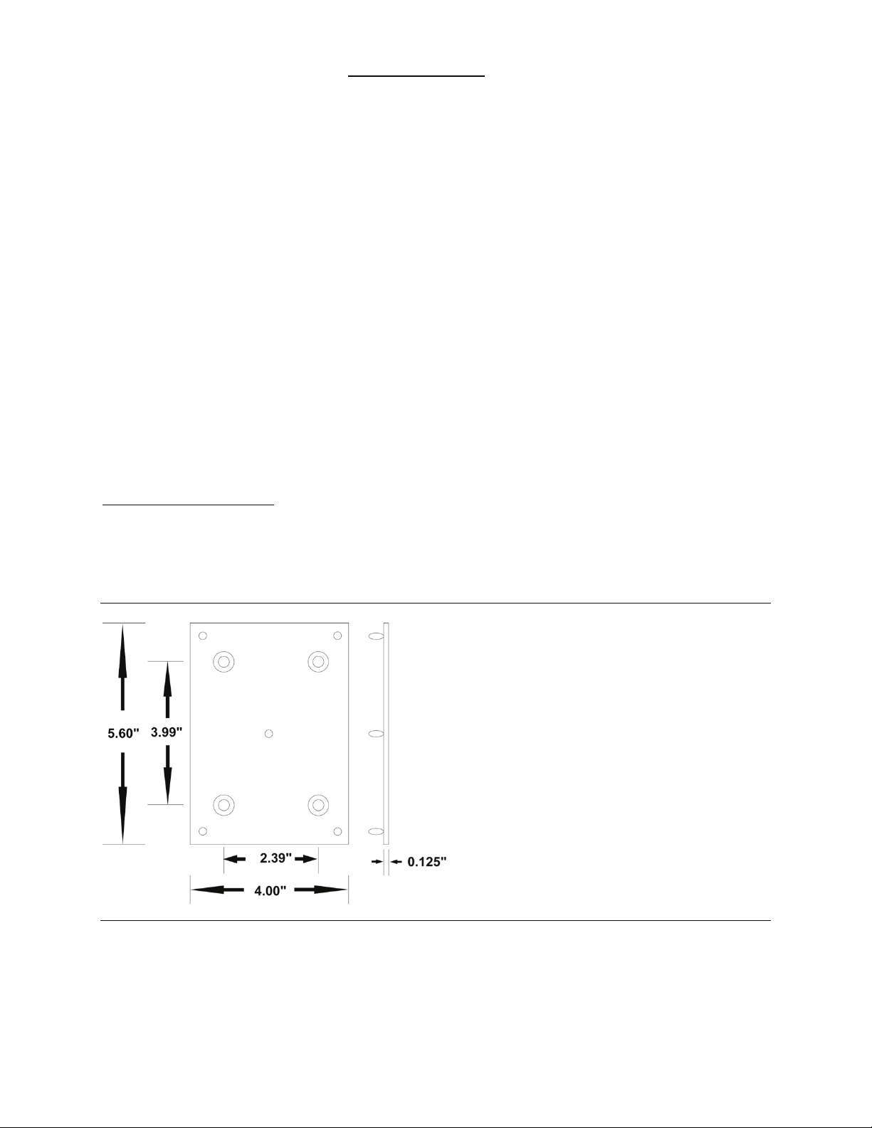
The Master is designed to sit on a desk or be mounted on a wall. Mounting hardware is
included for both options. For wall mounting, screw the mounting plate (included) to
the wall where Master unit is to be located with appropriate screws. The Master will
later mount on this plate.
Figure 1. Wall Mounting Plates for IW-HFM-4 Master
Talk-A-Phone Co. • 7530 North Natchez Avenue • Niles, Illinois 60714-3804 Page 4 of 13
Phone 773.539.1100 • Fax 773.539.1241 • info@talkaphone.com • www.talkaphone.com
All prices and specifications are subject to change without notice.
Talk-A-Phone, Talk-A-Lert, Scream Alert and WEBS are registered trademarks of Talk-A-Phone Co.
Copyright 2009 Talk-A-Phone Co. All rights reserved.
Page 5

2. Mounting the Optional Gooseneck Microphone or Headset
Plug the Gooseneck Microphone into the mini RJ11 plug labeled "GOOSENECK MIC"
on the back of the Master. Mount the Gooseneck Microphone so that the Interviewer
will be able to speak comfortably. (You may wish to mount the microphone
temporarily in order to try different locations before mounting permanently.)
For the wireless headset, attach via the mini RJ11 to the plug labeled "HEADSET" and
the plug labeled "TEL." on the handset base.
3. Connecting IW-HFM-4 Master to the Junction Box
The cable from the junction box connects to the RJ45 female connector on the back of the
Master. To avoid damage to the RJ45 male connector, cover this connector before
pulling through conduit or equivalent.
4. Connecting Sub-Station to Junction Box
The three-pair shielded cable from the Sub-Station should be connected to the white
“euro” type terminal block inside of the Junction Box. Connect all wires as shown in
the diagram below. Note that ALL 3 shields should be connected to the terminal
marked shield in the diagram below.
Figure 2. Master/Sub Terminal Block
IMPORTANT NOTE: Be sure to connect the white and black/white wires to the same
terminals as pictured above. Failure to do so may cause the power supply to overheat
and burn out.
5. Connecting the Paging Cable from the First Junction Box
The bus cable, which connects all Masters to the paging system, consists of a cable that
runs from one Junction Box to the next until they are all connected. At the end of the
Paging Bus, the Interface Boxes are all connected.
In the Junction Box for the first Master, connect all wires to similar terminals on the
Junction Box for the next Master as shown in Figure 3 below.
Note: Connect both shields to the terminal marked “SHLD”.
Talk-A-Phone Co. • 7530 North Natchez Avenue • Niles, Illinois 60714-3804 Page 5 of 13
Phone 773.539.1100 • Fax 773.539.1241 • info@talkaphone.com • www.talkaphone.com
All prices and specifications are subject to change without notice.
Talk-A-Phone, Talk-A-Lert, Scream Alert and WEBS are registered trademarks of Talk-A-Phone Co.
Copyright 2009 Talk-A-Phone Co. All rights reserved.
Page 6

Figure 3. First Master Junction Box Paging Connections
6. Connecting the Paging Cables of Intermediate IW-HF-4 Masters
In the Junction Box of intermediate Masters, connect wires from the previous Junction
Box and the next Junction Box to the same terminals as shown in Figure 4 below.
Note: Connect both shields to the terminal marked “SHLD”.
Figure 4. Intermediate Master Junction Box Paging Connections
7. Connecting Paging Cable from Last Master to First Interface Box
On the white “euro” type terminal block included with the Interface Box, connect all
wires from the paging bus cable from the last Master Junction Box to similar wires from
the Interface Box as shown in Figure 5 below. Then connect an identical set of
paging/control wires to the same terminals as the first set and continue this cable to the
terminal block of the next Interface Box. Note that the shields coming from the Interface
Box should not be connected and should be taped off to prevent shorting.
NOTE: As shipped, there are 620 Ohm, 1/2 watt resistors connected on each of the
pairs coming from the Interface Box. Be sure to remove these on all but the last
Interface Box.
If a music/program source is being used, connect another shielded pair from the music
terminals on the Interface Box to the last three terminals on the terminal block. Then
run this cable to the next Interface Box terminal strip or, if the paging zone is to receive
its own music program, connect directly to the source. If this is the last (or only)
Interface Box to which the music source is being connected, connect a 620 Ohm, 1/2
Watt terminating resistor (included) between the black & yellow terminals on the
Interface Box side of the terminal block as shown below.
Talk-A-Phone Co. • 7530 North Natchez Avenue • Niles, Illinois 60714-3804 Page 6 of 13
Phone 773.539.1100 • Fax 773.539.1241 • info@talkaphone.com • www.talkaphone.com
All prices and specifications are subject to change without notice.
Talk-A-Phone, Talk-A-Lert, Scream Alert and WEBS are registered trademarks of Talk-A-Phone Co.
Copyright 2009 Talk-A-Phone Co. All rights reserved.
Page 7

Figure 5. First Interface Box Wiring
8. Connecting Paging Bus Cable to Intermediate IW-IB-6 Interface Box
On the white terminal block included with the Interface Box, connect all wires from the
paging bus cable from the previous Interface Box to similar wires from the Interface Box
as shown in Figure 6 below. Then connect an identical set of paging bus wires to the
same terminals as the first set and continue this cable to the terminal block of the next
Interface Box. Note that the shields coming from the Interface Box should not be
connected and should be taped off to prevent shorting.
NOTE: As shipped, there are 620 Ohm, 1/2 watt resistors connected on each of the pairs
coming from the Interface Box. Be sure to remove these on all but the last Interface Box.
If a music/program source is being used, connect another shielded pair from the music
terminals on the Interface Box to the last three terminals on the terminal block. Then
run this cable to the next Interface Box terminal strip or, if the paging zone is to receive
its own music program, connect directly to the source. If this is the last (or only)
Interface Box to which the music source is being connected, connect a 620 Ohm, 1/2
Watt terminating resistor (included) between the black & yellow terminals on the
Interface Box side of the terminal block as shown below.
Talk-A-Phone Co. • 7530 North Natchez Avenue • Niles, Illinois 60714-3804 Page 7 of 13
Phone 773.539.1100 • Fax 773.539.1241 • info@talkaphone.com • www.talkaphone.com
All prices and specifications are subject to change without notice.
Talk-A-Phone, Talk-A-Lert, Scream Alert and WEBS are registered trademarks of Talk-A-Phone Co.
Copyright 2009 Talk-A-Phone Co. All rights reserved.
Page 8

Figure 6. Intermediate Interface Box Wiring
9. Connecting Paging Bus Cable to Final IW-IB-6 Interface Box
On the white terminal block included with the Interface Box, connect all wires from the
paging bus cable from the previous Interface Box to similar wires from the Interface Box
as shown in Figure 7 below. For the final Interface Box only leave the 620 Ohm, 1/2Watt
Terminating Resistors connected between each pair on the Interface Box side of the
terminal block.
If a music/program source is being used, connect another shielded pair from the music
terminals on the Interface Box to the last three terminals on the terminal block. Then
run this cable to the music/program source. For the final Interface Box only connect a 620
Ohm, 1/2 Watt terminating resistor (included, but not factory installed) between the
music source terminals on the Interface Box side of the terminal block as shown in
Figure 7 below.
Talk-A-Phone Co. • 7530 North Natchez Avenue • Niles, Illinois 60714-3804 Page 8 of 13
Phone 773.539.1100 • Fax 773.539.1241 • info@talkaphone.com • www.talkaphone.com
All prices and specifications are subject to change without notice.
Talk-A-Phone, Talk-A-Lert, Scream Alert and WEBS are registered trademarks of Talk-A-Phone Co.
Copyright 2009 Talk-A-Phone Co. All rights reserved.
Page 9

Figure 7. Final Interface Box Wiring
10. Connecting Speakers/K-HP-50 to IW-IB-6 Interface Box
Before opening the box to perform steps 9 or 10, be sure to unplug the wall
transformer from its power source. If there are only one or two speakers in a zone,
those speakers may be connected directly to the output terminals on the Interface Box,
(terminals A+ and A- located on the Interface board) which has an output of 2 1/2
Watts.
If more than two speakers are to be used, connect a K-HP-50 Paging Booster (A & B
terminals) to the output terminals of the Interface Box (A+ & A-). Then connect all
speakers to the 5 Watt terminals on the K-HP-50. Make sure the K-HP-50 is plugged in
and the power is on.
11. Setting the Zone on IW-IB-6 Interface Box
The zone of each Interface Box is determined by the position of a jumper labeled JB1 on
the circuit board. To set the zone, take off the cover and unscrew the 4 screws holding
the chassis/circuit board in the box. Flip this over to see the 6 sets of pins on the bottom
right area of the board. A jumper connects one set of pins. Remove the jumper and
place it on the numbered pins that match the designated Zone number of the Interface
Box. At this point you should connect the power supply to the Interface Box (but do not
plug in until all connections are complete) as well as the music source (if used). When
this is complete, reassemble the Interface Box.
12. Setting Button 2 and 3 Zones on the IW-HFM-4 Master
The 2nd and 3rd buttons on the Master units can each be set to page any of the zones in
your system. Typically, button 2 will page the Master unit’s local zone while button 3
will page an adjacent zone. There is a small access opening on the back of the Master.
You will see two 6-position dip-switches labeled for switch two and for switch three.
Set the two switches to the appropriate zones.
Talk-A-Phone Co. • 7530 North Natchez Avenue • Niles, Illinois 60714-3804 Page 9 of 13
Phone 773.539.1100 • Fax 773.539.1241 • info@talkaphone.com • www.talkaphone.com
All prices and specifications are subject to change without notice.
Talk-A-Phone, Talk-A-Lert, Scream Alert and WEBS are registered trademarks of Talk-A-Phone Co.
Copyright 2009 Talk-A-Phone Co. All rights reserved.
Page 10

13. Connecting the Master to the Mounting Plate (if master is desk mounted)
Using the five Pem fasteners, attach the Master to the Wall (see Figure 1) by simply
pressing the Master onto the Pem fasteners.
14. Surface Mounting the Sub-Station
Mount the Sub-Station to the wall using the four holes in the mounting plate attached to
the back of the unit
15. Adjusting the incoming volume on the Sub-Station.
The volume on the Sub-Station is preset at the factory to a level suitable in most
applications. Should the installer wish to adjust the volume, this can be done by
adjusting the small trimmer located directly behind the small hole on the left side of the
faceplate. A tool is included along with each shipment for this purpose. For best
results, make your adjustments while someone is talking to you through the speaker.
16. Connecting Wall Transformers
Connect the Master to its Wall Transformer. Also be sure that all Interface Boxes and
Junction Boxes are connected to their Wall Transformers. (Note: Wall transformer in
Interface Box connects to jack located on the board of the Interface, and is connected
when unit is open for setting zone and connecting speakers.)
17. Setting Up Wireless Headset (if used)
Connect the base of the wireless unit to the Master. Connect the mini RJ11 to the TEL
connection on the bottom of the base unit.
The TALK volume on the side of the headset base unit controls outgoing volume. It
should be set to minimum to start then adjusted as necessary. Incoming volume can be
adjusted on the belt clip. The ringer on the remote unit should be set to OFF. To
activate the unit, the TALK button must be pushed.
Talk-A-Phone Co. • 7530 North Natchez Avenue • Niles, Illinois 60714-3804 Page 10 of 13
Phone 773.539.1100 • Fax 773.539.1241 • info@talkaphone.com • www.talkaphone.com
All prices and specifications are subject to change without notice.
Talk-A-Phone, Talk-A-Lert, Scream Alert and WEBS are registered trademarks of Talk-A-Phone Co.
Copyright 2009 Talk-A-Phone Co. All rights reserved.
Page 11

BASIC SYSTEM OPERATION
The control panel on the lower front panel of the Master must be set to Position 1 if
only the built-in speaker and microphone are being used (no external microphone or
headset is being used), Position 2 if the RF Headset is in use, or Position 3 if the
Gooseneck Microphone is being used without a headset. Set the Incoming Volume on
the control panel to a comfortable level.
At each window, pressing the WIN button selects the sub-station at that window for a
hands-free conversation between the visitor and the receptionist. Each receptionist
position can also selectively call two zones (which relate to their position) as well as do
an “All Call” with the fourth button. All buttons remain “in” until pushed a second
time, which releases them.
The volume control on the Master adjusts the incoming volume at the Master, whether
heard through the master’s speaker or the optional wireless headset. In addition, the
headset has its own volume control for headset volume. If the headset is being used,
the TALK button must be pressed to activate or deactivate it.
To avoid multiple simultaneous paging, a light centered above the three Zone Paging
Buttons indicates that the paging system is in use and the interviewer should wait until
the light is out before attempting to page.
Prerecorded announcements (if used in this system) can be selectively broadcast to a
specific zone or heard in all areas over the paging speakers, unless that particular zone
is being paged (or an All Call is in progress). In that event, that zone and that zone
only, automatically hears the page and not the prerecorded announcement.
The IW-HFS-1H handset sub-station enables handset communication while the handset
is off-hook. When on hook, the IW-HFS-1H operates as a hands-free sub-station.
Talk-A-Phone Co. • 7530 North Natchez Avenue • Niles, Illinois 60714-3804 Page 11 of 13
Phone 773.539.1100 • Fax 773.539.1241 • info@talkaphone.com • www.talkaphone.com
All prices and specifications are subject to change without notice.
Talk-A-Phone, Talk-A-Lert, Scream Alert and WEBS are registered trademarks of Talk-A-Phone Co.
Copyright 2009 Talk-A-Phone Co. All rights reserved.
Page 12

OVERVIEW OF INTERFACE BOX CIRCUIT BOARD
Copyright 2009 Talk-A-Phone Co. All rights reserved.
Phone 773.539.1100 • Fax 773.539.1241 • info@talkaphone.com • www.talkaphone.com
Talk-A-Phone, Talk-A-Lert, Scream Alert and WEBS are registered trademarks of Talk-A-Phone Co.
Talk-A-Phone Co. • 7530 North Natchez Avenue • Niles, Illinois 60714-3804 Page 12 of 13
All prices and specifications are subject to change without notice.
Page 13

TALK-A-PHONE CO. LIMITED WARRANTY
Talk-A-Phone Co. warrants Talk-A-Phone equipment against any defects in material
and workmanship, under normal use, for a period of twenty-four (24) months from date
of installation, provided that Talk-A-Phone receives a completed "Installation
Certification" certifying the date on which the system has been installed. An
"Installation Certification" card is enclosed with every unit. In the event that no
"Installation Certification" is received by Talk-A-Phone, the twenty-four (24) months
will commence on the date of shipment by Talk-A-Phone
In the event this product is found by Talk-A-Phone to be defective within the warranty
period, Talk-A-Phone's only obligation and your exclusive remedy shall be the repair
and/or replacement of any defective parts, provided the equipment is returned to
Talk-A-Phone Co., 7530 North Natchez Avenue, Niles, IL 60714. It is expressly
understood that Talk-A-Phone shall have no obligation to furnish labor, nor pay for the
labor of any third parties, nor bear the expense of shipping defective products for
repair. This warranty shall not apply if Talk-A-Phone determines the defect was caused
by improper use or installation or damage caused to the equipment by others.
THIS WARRANTY GIVES YOU SPECIFIC LEGAL RIGHTS AND YOU MAY ALSO
HAVE OTHER RIGHTS WHICH VARY FROM STATE TO STATE.
TALK-A-PHONE FACTORY SERVICE
Talk-A-Phone factory service is available to Talk-A-Phone users at a reasonable charge,
plus transportation to and from our factory. When you send units to our factory,
freight prepaid, our technicians will examine, service and promptly return the units to
you, transportation collect. You must receive a Return Materials Authorization (RMA)
number to send units in for repair. Contact the Talk-A-Phone Service department for
more information.
Talk-A-Phone also sells replacement components for our products directly both to
dealers and to our users. When ordering, please give either the component part
number or a brief description of the component’s function, and the model for which it is
needed. When returning equipment for service or ordering replacement parts, please
be sure to include your full name, address and telephone number.
If you have any questions regarding this system, feel free to contact Talk-A-Phone Co.
Technical Service by telephone, fax, or e-mail.
Talk-A-Phone Co. • 7530 North Natchez Avenue • Niles, Illinois 60714-3804 Page 13 of 13
Phone 773.539.1100 • Fax 773.539.1241 • info@talkaphone.com • www.talkaphone.com
All prices and specifications are subject to change without notice.
Talk-A-Phone, Talk-A-Lert, Scream Alert and WEBS are registered trademarks of Talk-A-Phone Co.
Copyright 2009 Talk-A-Phone Co. All rights reserved.
 Loading...