

Page 1

Pedestal Mount Installation Instructions
I. Introduction
NOTE: This manual is for anchor bolts installation into the foundation and the pedestal installation for models
ETP-PM, ETP-PM-SS, ETP-PMD, and ETP-PMD-SS.
II. Contents
Before beginning installation, make sure you have all the included components. Each Pedestal consists of two
packages. Package #1 contains the pedestal itself. Package #2, labeled PARTS contains the following:
Anchor Bolt Install Kit
QTY Part Number Description
4 42838 J-Bolts
1 24717 Aluminum Template
Pedestal Install Kit (keep for use when installing the pedestal)
QTY Part Number Description
6 42867 10-24 x3/4" oval head tamperproof screw
8 42839 3/4"-10 Hex Nut
8 42840 3/4" Washer
2 42843 6-32 hex nut
1 67478 Polycarbonate light cover
1 68590 LED light board (12-24V AC/DC - 120VAC)
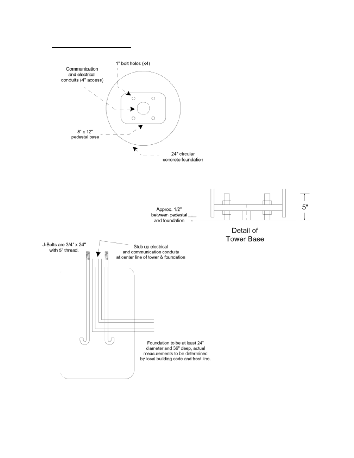
III. Foundation Preparation
1. Electrical and telephone line conduits should be run through the foundation and into the center 4"
diameter hole of the pedestal.
NOTE: To insure proper grounding of all electrical components, the pedestal mount should be
effectively earth grounded from the grounding stud (located across from the lower access panel) with
6 AWG or better insulated, stranded copper wire to the metallic power service raceway (conduit) or an
8 foot or longer corrosion-resistant ground spike. It is the installer's obligation to ensure compliance
with all national, regional, and local regulations.
2. Pour the foundation at least 2 feet in diameter and 3 feet deep according to your local code and frost
line (see foundation drawing on following page).
3. Install the four (4) 3/4” - 10 x 24 long anchor bolts below grade with five inches (5”) projecting
above grade (see foundation drawing on following page). Use the template provided to properly
position the bolts within the concrete foundation.
NOTE: Make sure all connections meet National, Regional, and Local Electric Codes.
Talk-A-Phone Co. • 7530 North Natchez Avenue • Niles, Illinois 60714-3804 Rev. 4/7/2014
Phone 773.539.1100 • Fax 773.539.1241 • info@talkaphone.com • www.talkaphone.com
All prices and specifications are subject to change without notice.
Talk-A-Phone, Talk-A-Lert, Scream Alert and WEBS are registered trademarks of Talk-A-Phone Co.
Copyright 2014 Talk-A-Phone Co. All rights reserved.
Page 2
Pedestal Mount Installation Instructions
IV. ETP-PM Foundation Drawing
Talk-A-Phone Co. • 7530 North Natchez Avenue • Niles, Illinois 60714-3804 Page 2 of 3
Phone 773.539.1100 • Fax 773.539.1241 • info@talkaphone.com • www.talkaphone.com
All prices and specifications are subject to change without notice.
Talk-A-Phone, Talk-A-Lert, Scream Alert and WEBS are registered trademarks of Talk-A-Phone Co.
Copyright 2014 Talk-A-Phone Co. All rights reserved.
Page 3

Pedestal Mount Installation Instructions
V. Pedestal Installation
1. A polycarbonate light cover protects the LED light assembly from the inside. Peel the protective paper
off the light cover and fit it onto the studs inside the pedestal. Slide the LED board over the studs with
the LEDs facing down. The built-in spacers will keep the LEDs from resting on the acrylic window.
Tighten down using the enclosed #6 lock washers and nuts. Be careful not to over-tighten to avoid
cracking the circuit board.
2. Install one 3/4” nut and one washer on each anchor bolt 2.5” above grade to top of washer. This will
allow for a 1/2" air gap between the foundation and the pedestal, which will allow airflow and prevent
moisture problems. Verify that the nuts are level (0° pitch).
NOTE: To insure proper grounding of all electrical components, the pedestal mount should be
effectively earth grounded from the grounding stud (located across from the lower access panel) with
6 AWG or better insulated, stranded copper wire to the metallic power service raceway (conduit) or an
8' or longer corrosion-resistant ground spike.
After removing the cover plate from the pedestal’s rear access opening, install the pedestal onto the
bolts with the Emergency Phone opening oriented in the desired direction. Install second set of nuts
and washers. Tighten the upper nuts; the bottom set is only for leveling.
3. Wire incoming power to the faceplate light. The LED board operates on 12VDC up to 120VAC and is
not polarity sensitive.
4. Attach the Emergency Phone to the pedestal with six (6) 10-24 oval head tamperproof screws. If you
have a model ETP-PMD Dual Pedestal Mount, use the other six (6) screws to mount your second
faceplate. Connect the phone line coming into the pedestal to the male RJ11 connector coming from
the Emergency Phone. An outdoor rated RJ11 female modular jack on the end of the incoming phone
line is strongly recommended.
5. Re-attach the cover plate over the access opening.
It is the installer's obligation to ensure compliance with all national, regional, and local regulations.
Talk-A-Phone Co. • 7530 North Natchez Avenue • Niles, Illinois 60714-3804 Page 3 of 3
Phone 773.539.1100 • Fax 773.539.1241 • info@talkaphone.com • www.talkaphone.com
All prices and specifications are subject to change without notice.
Talk-A-Phone, Talk-A-Lert, Scream Alert and WEBS are registered trademarks of Talk-A-Phone Co.
Copyright 2014 Talk-A-Phone Co. All rights reserved.
 Loading...