

Page 1
Solar Kit Installation Instructions
Qty.
Part Number
Description
4
42838
J-bolts
1
26301
MT Cardboard Template
Qty.
Part Number
Description
4
42838
J-bolts
1
26312
MT/R Cardboard Template
Qty.
Part Number
Description
8
42839
3/4"-10 Hex Nut
8
42840
3/4" Washer
3
42841
10-24 x 3/4" pan head tamperproof screw
2
42843
6-32 hex nut
1
67478
Polycarbonate light cover
1
68590
LED light board (12-24V AC/DC - 120VAC)
1
ETP-EL12/24
12/24V AC/DC LED Blue Light
THIS PRODUCT MUST BE INSTALLED IN ACCORDANCE WITH THE
APPLICABLE INSTALLATION CODE BY A PERSON FAMILIAR WITH THE
CONSTRUCTION AND OPERATION OF THE PRODUCT AND THE HAZARDS
INVOLVED
CE PRODUIT DOIT ÊTRE INSTALLÉ SELON LE CODE D’INSTALLATION
PERTINENT, PAR UNE PERSONNE QUI CONNAÎT BIEN LES PRODUIT ET
SON FONCTIONNEMENT AINSI QUE LES RISQUES INHÉRENTS
I. Introduction
This manual is for the installation of solar kits SLR-80-84 and SLR-120-84. For instructions on installing the
anchor bolts into the foundation, see the Tower Anchor Bolt Installation Instructions for ETP-MTE Series
and ETP-MT/R Series towers.
II. Package Contents
Before beginning installation, make sure you have all the included components. Each ETP-MTE-WP and
ETP-MT/R OP SOLAR tower consists of the following packages: Packages 1 and 2 contain the tower
enclosure and wireless pole mount. Package 3 contains the anchor bolts and template for foundation
preparation. Package 4 labeled TOWER PTS SOLAR contains the lighting and hardware for tower
assembly. Package 5 contains either solar kit SLR-80-84 or SLR-120-84. Emergency phones and
wireless communication devices are sold and shipped separately.
Package 3: MT BOLT KIT
OR
MT/R BOLT KIT
Package 4: TOWER PTS SOLAR
Copyright 2013 Talk-A-Phone Co. • 7530 North Natchez Avenue • Niles, Illinois 60714 • Phone 773.539.1100 • info@talkaphone.com • www.talkaphone.com. Rev. 04/12/2013
All specifications are subject to change without notice. Talk-A-Phone is a registered trademark of Talk-A-Phone Co. All rights reserved. Page 1 of 25
Page 2
Solar Kit Installation Instructions
Qty.
Description
2
Bucket (Bracket)
4
Hose Clamp
2
Clip -Left (Bracket)
2
Clip -Right (Bracket)
2
Mounting Rail
4
Support Rail
4
1/4-20 x 3/4” SS hex-cap bolt
4
1/4 flat washer, SS
8
1/4 split lock washer, SS
4
1/4 hex nut, SS
22
5/16-18 x 3/4” SS hex-cap bolt
44
5/16 flat washer, SS
22
5/16 split lock washer, SS
22
5/16 hex nut, SS
1
1/4-20 and 5/16 x 3/4” Spare Kit
Qty.
Part Number
Description
2
68594
42 Ah batteries
1
68681
Solar Controller
2
42855
10-24 Screws for mounting Solar Controller
2
42847
10-24 Nuts for mounting Solar Controller
6
67547
Terminal - Spade/Fork, #6 Tab, 12-10 AWG
20 ft
19678
Cable, Solar - 12AWG, Tray Cable, 2C, Black-Red
6
67545
Terminal - Ring , 0.25", 12-10 AWG
EITHER
1
68689
PV (photovoltaic) Module, 80W 12VDC (SLR-80-84 only)
1
24701
Panel Mounting Bracket for SLR-80-84
OR
1
68680
PV (photovoltaic) Module, 120-140W 12VDC (SLR-120-84 only)
1
24705
Panel Mounting Bracket for SLR-120-84
Qty.
Description
1
Large Bucket (Bracket)
1
Small Bucket (Bracket)
3
Hose Clamp
1
Clip – Left (Bracket)
1
Clip – Right (Bracket)
2
Mounting Rail
2
C-Bracket
2
Support Channel – Inner
2
Support Channel – Outer
10
1/4-20 x 3/4” SS hex-cap bolt
2
1/4-20 x 2” SS hex-cap bolt
2
1/4-20 x 1 5/8” SS hex-cap bolt
16
1/4 flat washer, SS
4
1/4 split lock washer, SS
12
1/4-20 hex nut, SS
4
5/16-18 x 3/4” SS hex-cap bolt
8
5/16 flat washer, SS
4
5/16 split lock washer, SS
4
5/16 hex nut, SS
1
1/4-20 and 5/16 x 3/4” Spare Kit
Package 5: SLR-80-84 and SLR-120-84
24701: SLR-80-84 Panel Mounting Bracket Kit
24705: SLR-120-84 Panel Mounting Bracket Kit
Copyright 2013 Talk-A-Phone Co. • 7530 North Natchez Avenue • Niles, Illinois 60714 • Phone 773.539.1100 • info@talkaphone.com • www.talkaphone.com. Page 2 of 25
All specifications are subject to change without notice. Talk-A-Phone is a registered trademark of Talk-A-Phone Co. All rights reserved.
Page 3
Solar Kit Installation Instructions
III. Tower Enclosure Installation
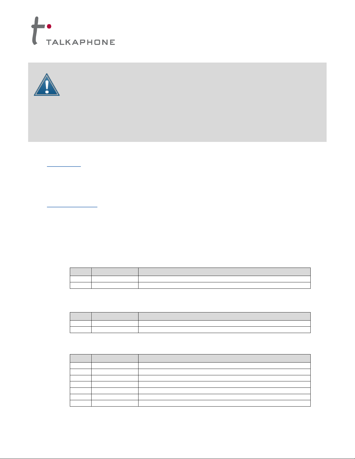
1. Remove the tower’s rear bottom access panel by removing tamper-proof screws.
2. Install one 3/4” leveling nut and one washer on each anchor bolt 2 ½” - 3 ½” above grade and verify that
nuts are level (0° pitch) as shown in Figure 1.
Figure 1. Tower Enclosure Installation
3. Install the tower onto the leveling bolts with the emergency phone opening oriented in the direction
desired. Install the second set of nuts and washers. Tighten the upper fastening nuts; the bottom set is
only for leveling.
IV. Solar Panel Installation
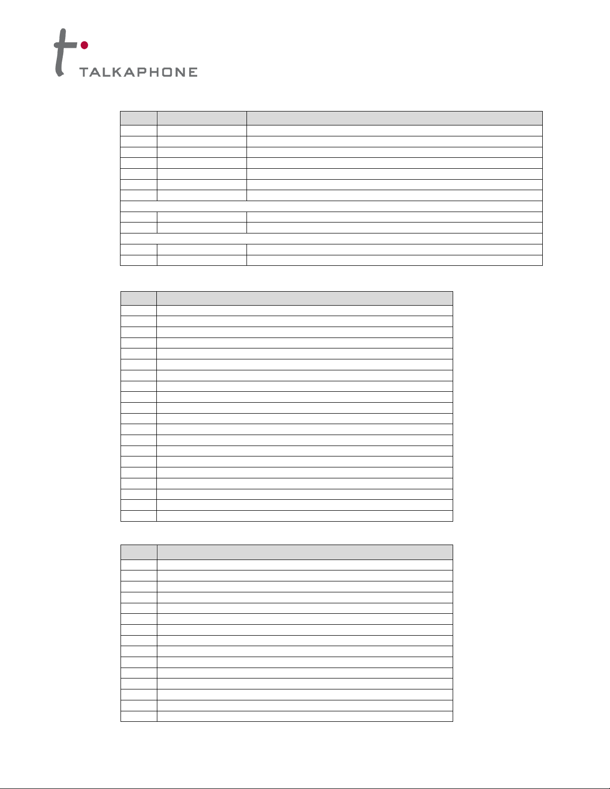
1. Lay the solar panel face down on a protected flat surface.
2. Place the mounting rails on the back of the panel so the lip of the rail containing the panel mounting
slots/holes are facing the center of the panel as shown in Figure 2. Align one end of the rails to be
approximately flush with the bottom edge of the panel.
Figure 2. Mounting rails placed on rear surface of solar panel
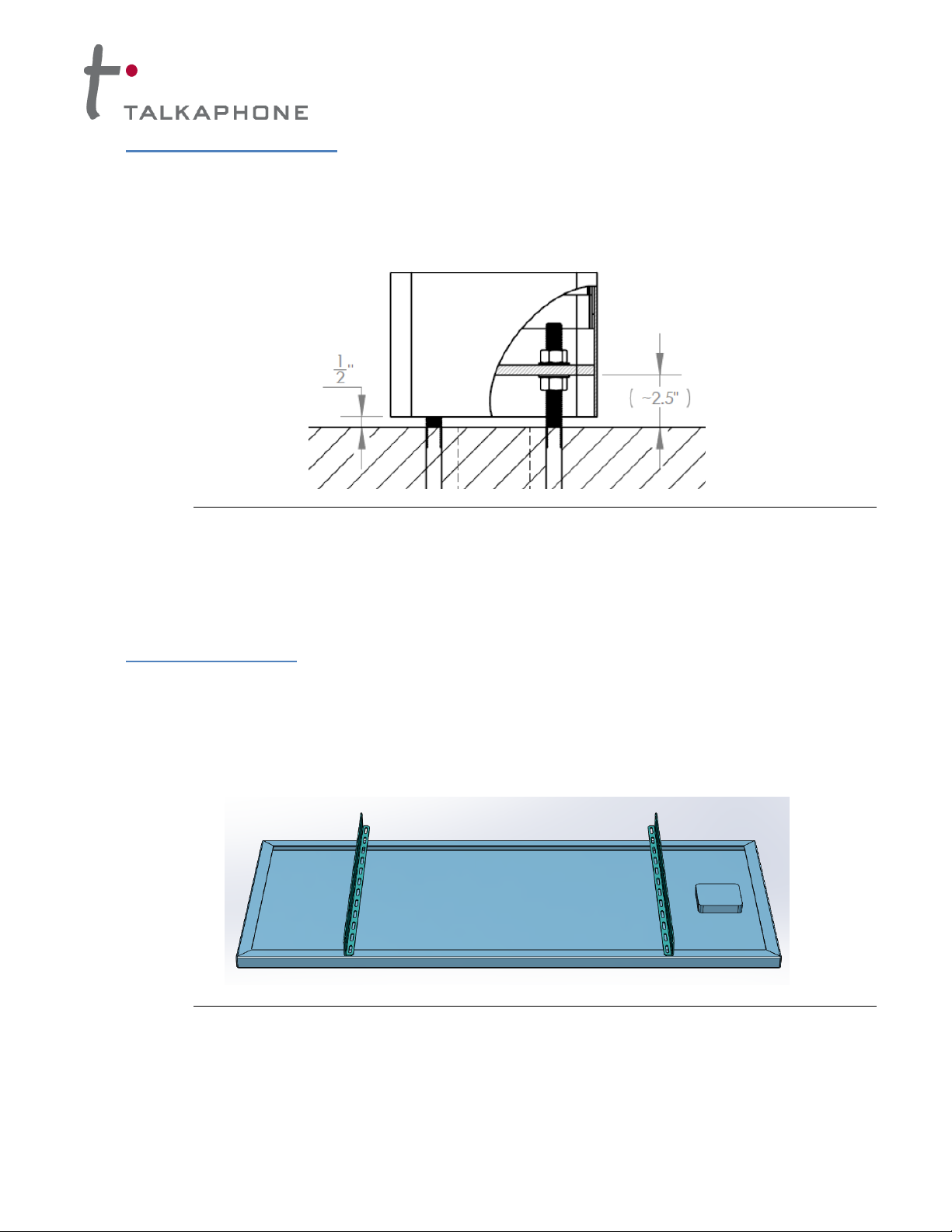
3. Secure the mounting rails with a 1/4 - 20 x 3/4” bolt, flat washer, lock washer and hex nut in each of the
panel mounting holes (4 per panel) as shown in the Figure 3. Tighten the bolts to 7 ft-lbs.
Copyright 2013 Talk-A-Phone Co. • 7530 North Natchez Avenue • Niles, Illinois 60714 • Phone 773.539.1100 • info@talkaphone.com • www.talkaphone.com. Page 3 of 25
All specifications are subject to change without notice. Talk-A-Phone is a registered trademark of Talk-A-Phone Co. All rights reserved.
Page 4
Solar Kit Installation Instructions
Figure 3. Mounting rail fastened to the panel frame
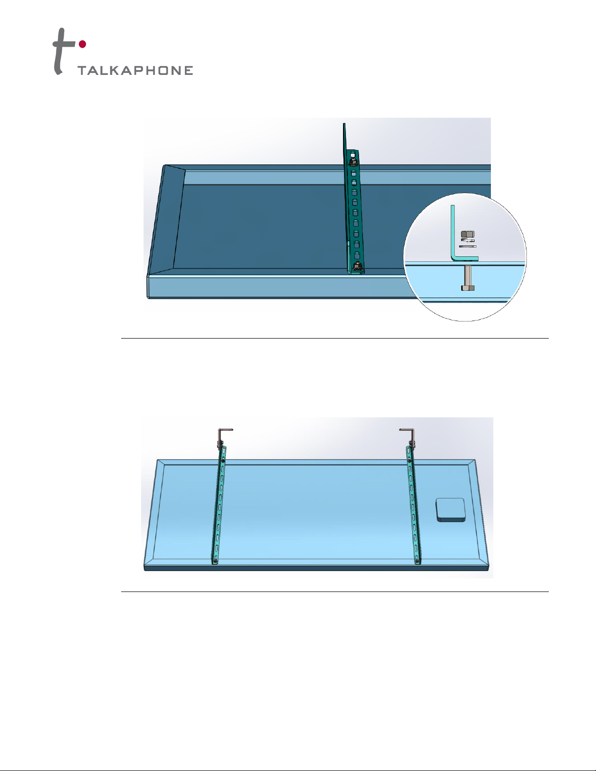
4. Attach the clips to the rails so that the flanged end containing the slots on the clips are facing the center
of the panel as shown in Figure 4.
Figure 4. Orientation of clips with reference to solar panel
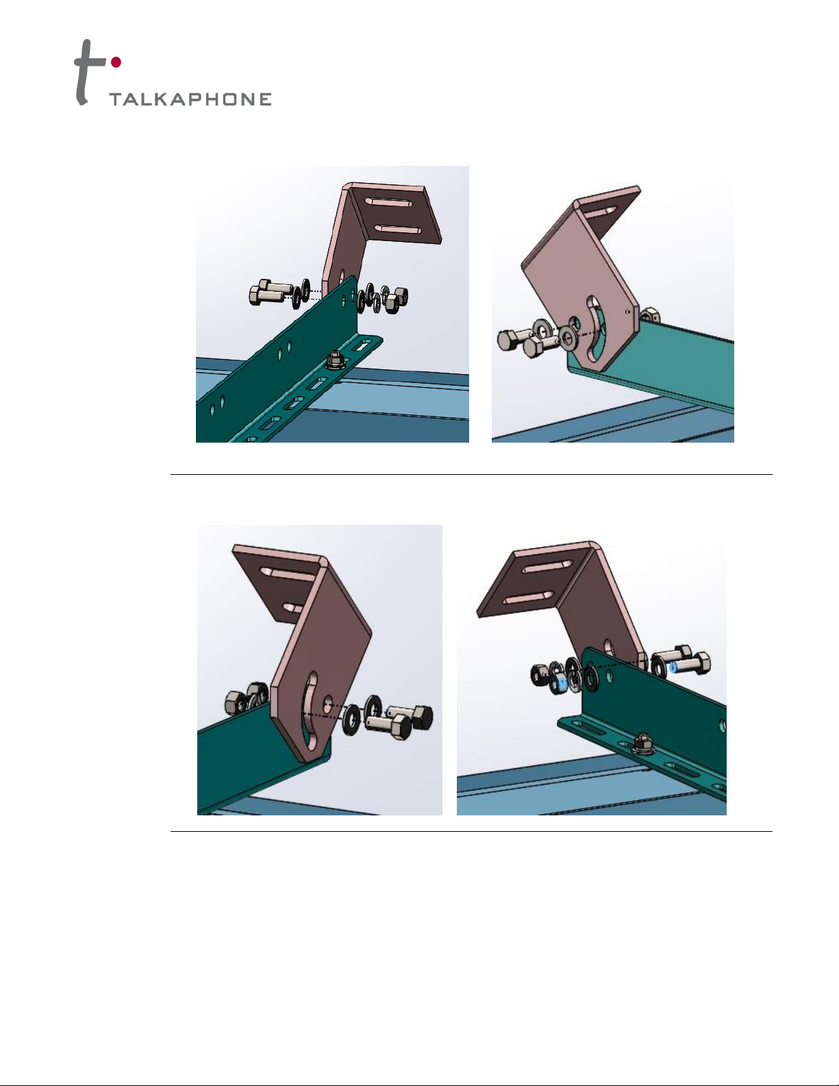
5. Attach the clips to the rails. In each of the mounting holes, use a 5/16 - 18 x 3/4” bolt and flat washer on
one side and a flat washer, lock washer and nut on the other as shown in Figures 5 & 6. Tighten the
bolts to hold in place securely.
Copyright 2013 Talk-A-Phone Co. • 7530 North Natchez Avenue • Niles, Illinois 60714 • Phone 773.539.1100 • info@talkaphone.com • www.talkaphone.com. Page 4 of 25
All specifications are subject to change without notice. Talk-A-Phone is a registered trademark of Talk-A-Phone Co. All rights reserved.
Page 5
Solar Kit Installation Instructions
Figure 5. Exploded view of left clip attached to the left mounting rail
Figure 6. Exploded view of right clip attached to the right mounting rail
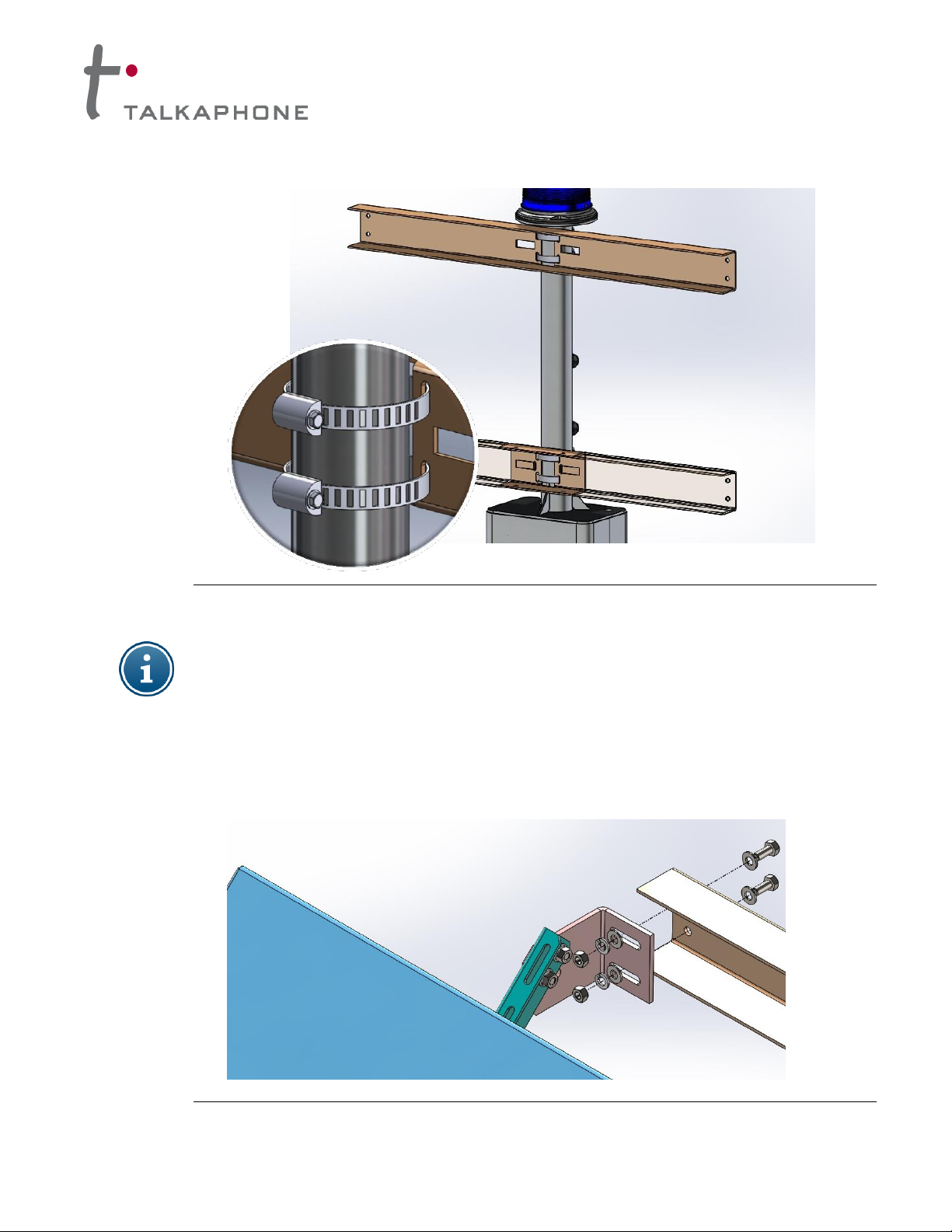
6. To install the bucket brackets, thread each hose clamp through one of the sets of narrow center holes as
shown in Figure 7. Place the buckets at the desired location on the pole approximately 18 inches apart.
The spacing can be adjusted later. Tighten the hose clamp screws to 70 in-lbs.
Copyright 2013 Talk-A-Phone Co. • 7530 North Natchez Avenue • Niles, Illinois 60714 • Phone 773.539.1100 • info@talkaphone.com • www.talkaphone.com. Page 5 of 25
All specifications are subject to change without notice. Talk-A-Phone is a registered trademark of Talk-A-Phone Co. All rights reserved.
Page 6
Solar Kit Installation Instructions
Figure 7. Mounting buckets attached to the pole using hose clamps
For countries in the northern hemisphere (U.S.A., Canada, Mexico) all solar panels should
be installed facing south.
7. Place the solar panel assembly so the slots on the clips line up with holes inside of the bucket as shown
in Figure 8. Bolt the clips to the bucket using 5/16 - 18 x 3/4” hex cap bolt and flat washer on one side,
and a washer, lock washer and nut on the other. Tighten the bolts to 12 ft-lbs.
Figure 8. Exploded view of the right side clip installed to the upper bucket bracket
Copyright 2013 Talk-A-Phone Co. • 7530 North Natchez Avenue • Niles, Illinois 60714 • Phone 773.539.1100 • info@talkaphone.com • www.talkaphone.com. Page 6 of 25
All specifications are subject to change without notice. Talk-A-Phone is a registered trademark of Talk-A-Phone Co. All rights reserved.
Page 7
Solar Kit Installation Instructions
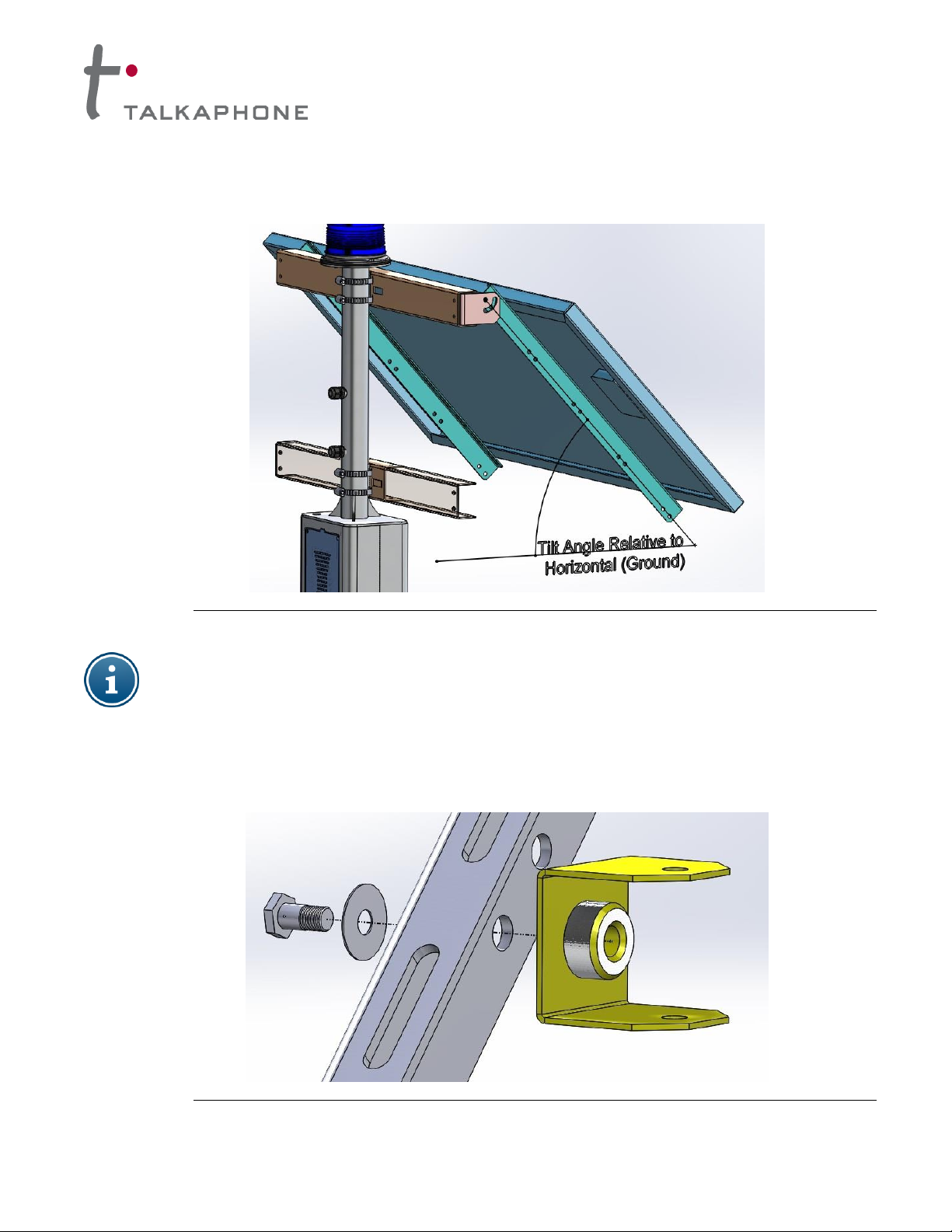
8. Refer to Appendix A for correct tilt angle according to geographic location. To adjust the tilt angle
loosen the bolts holding the mounting rails to the clips and adjust the tilt of the panel as shown in Figure
9. Retighten the bolts to 12 ft-lbs.
Figure 9. Panel tilt angle reference
Steps 9 – 12 are for solar kit SLR-80-84 only. For solar kit SLR-120-84, skip to step 13.
9. Attach the C-brackets to the inside face of the mounting rails using a 1/4-20 x 3/4” hex bolt and washer
through one of the center holes as shown in Figure 10. Tighten the bolt securely so that the C-bracket
flanges are level and with the flanges of the lower bucket bracket.
Figure 10. Exploded view of C-bracket installation inside of mounting rail
Copyright 2013 Talk-A-Phone Co. • 7530 North Natchez Avenue • Niles, Illinois 60714 • Phone 773.539.1100 • info@talkaphone.com • www.talkaphone.com. Page 7 of 25
All specifications are subject to change without notice. Talk-A-Phone is a registered trademark of Talk-A-Phone Co. All rights reserved.
Page 8
Solar Kit Installation Instructions
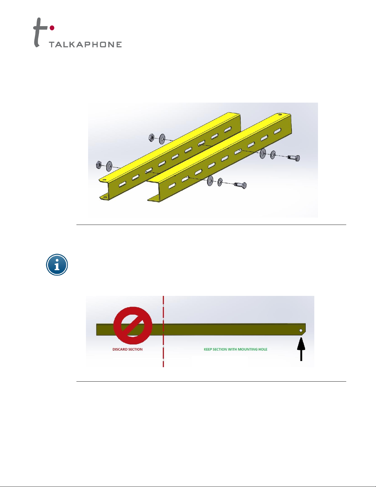
10. To assemble the support rails, fit the smaller inner channel inside the larger outer channel so that the
mounting holes on the flanges are opposite one another. Slide the channels to obtain the correct length
determined by the panel tilt angle. Secure the support rails together at the desired length using a 1/4-20
x 3/4” hex bolt, lock washer, and flat washer on one side, and a flat washer and hex nut on the other side
(2 per rail assembly) as shown in Figure 11.
Figure 11. Support rail assembly
NOTE: For northern regions where a tilt angle of 65º or greater is required, it may be necessary to
reduce the length of the support rails. If so, ensure that excess material is not discarded from the
end with the mounting holes on the flanges. See Figure 12.
Figure 12. Discard section for larger tilt angles (65º and above)
11. Use the assembled support rail to adjoin the mounting rails and the lower bucket bracket using a bolt,
washers, and hex nut as shown in Figure 13. Mount the support rail assembly to the C-brackets using
1/4-20 x 1 5/8” hex bolt and to the lower bucket bracket using a 1/4-20 x 2” hex bolt. Tighten bolts to 7 ft-
lbs.
Copyright 2013 Talk-A-Phone Co. • 7530 North Natchez Avenue • Niles, Illinois 60714 • Phone 773.539.1100 • info@talkaphone.com • www.talkaphone.com. Page 8 of 25
All specifications are subject to change without notice. Talk-A-Phone is a registered trademark of Talk-A-Phone Co. All rights reserved.
Page 9

Solar Kit Installation Instructions
Figure 13. Secure support rails to panel mounting rail and lower bucket bracket
12. Once all adjustments are complete, ensure that all hardware is adequately tightened to specifications
listed below.
Figure 14. Assembled view of SLR-80-84 (shown on ETP-MTE-WP)
Copyright 2013 Talk-A-Phone Co. • 7530 North Natchez Avenue • Niles, Illinois 60714 • Phone 773.539.1100 • info@talkaphone.com • www.talkaphone.com. Page 9 of 25
All specifications are subject to change without notice. Talk-A-Phone is a registered trademark of Talk-A-Phone Co. All rights reserved.
Page 10

Solar Kit Installation Instructions
Steps 13 – 18 are for solar kit SLR-120-84 only. For solar kit SLR-80-84 complete steps 9-12 and
proceed to section V: Mechanical Installation
13. Bolt the remaining two clips to the lower bucket using the 5/16-18 x 3/4" bolt and flat washer on one end
and a flat washer with a lock washer under the nut on the other end as shown in Figure 15.
Figure 15. Installation of the clips to the lower bucket
14. The support rails will need to be customized based on the optimum tilt angle of the solar panel:
a. For optimum tilt angles of 40-45º, use the entire support rail as shown in Figure 16.
Figure 16. Support rail length for a solar panel with a tilt angle of 40-45º
Copyright 2013 Talk-A-Phone Co. • 7530 North Natchez Avenue • Niles, Illinois 60714 • Phone 773.539.1100 • info@talkaphone.com • www.talkaphone.com. Page 10 of 25
All specifications are subject to change without notice. Talk-A-Phone is a registered trademark of Talk-A-Phone Co. All rights reserved.
Page 11
Solar Kit Installation Instructions
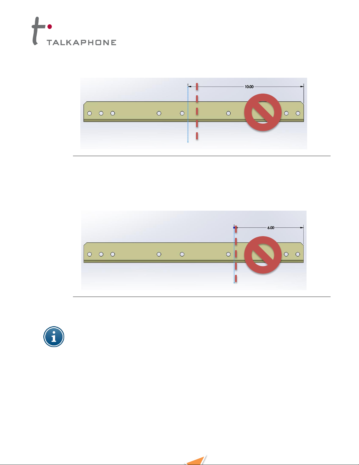
b. For optimum tilt angles of 50-60º, cut and discard the section 10 inches from the right as shown
in Figure 17.
Figure 17. Support rail length for a solar panel with a tilt angle of 50-60º
c. For an optimum tilt angle of 65º, cut and discard the section 6 inches from the right as shown in
Figure 18.
Figure 18. Support rail length for a PV module with a tilt angle of 65º
NOTE: For tilt angles ranging from 40-65º, two supporting rails are required out of the four
provided. For angles of 35 degrees and less, the support rails may be extended using the other
two rails (two support rails for each mounting rail).
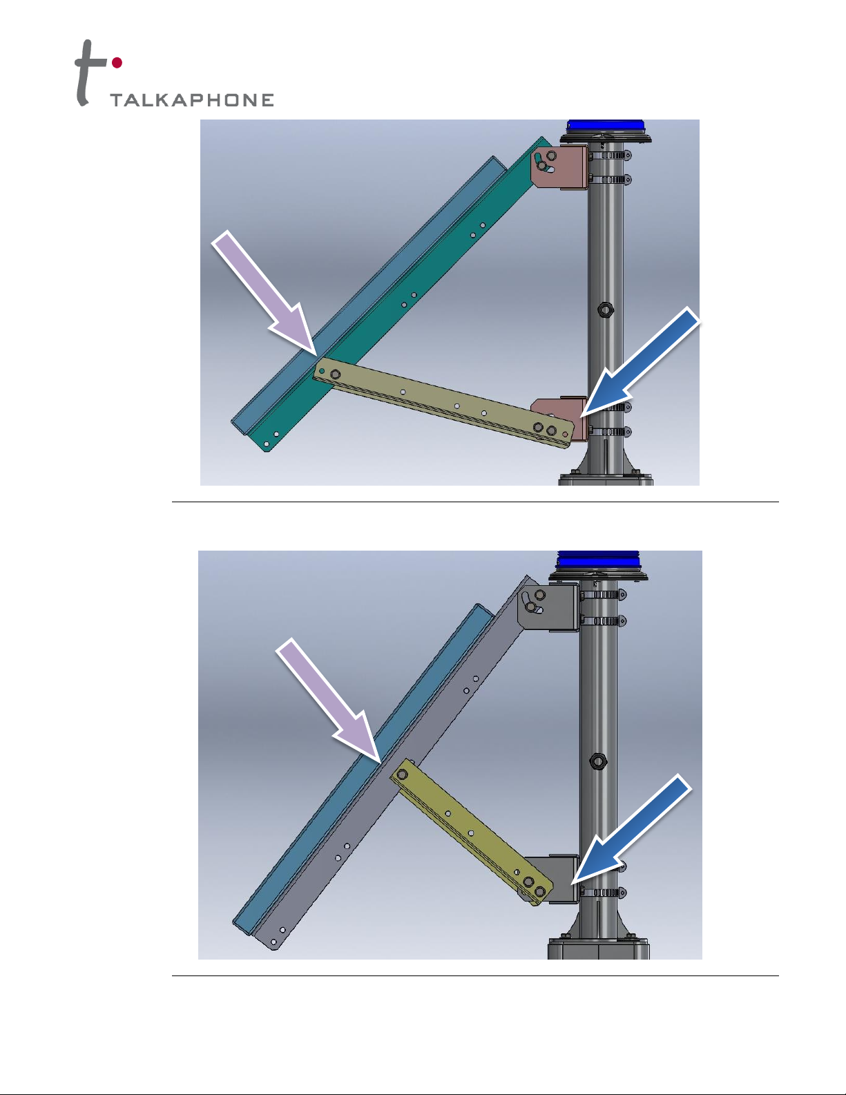
15. Attach one end of the support rail to the lower bucket and attach the other end to the corresponding
panel mounting rail using a 5/16 - 18 x 3/4” bolt, flat washers with a lock washer under the nut. Note the
orientation of the rail depending on the panel tilt angle as shown in Figures 19 - 23. Tighten the bolts at
both ends to 12 ft-lbs.
Copyright 2013 Talk-A-Phone Co. • 7530 North Natchez Avenue • Niles, Illinois 60714 • Phone 773.539.1100 • info@talkaphone.com • www.talkaphone.com. Page 11 of 25
All specifications are subject to change without notice. Talk-A-Phone is a registered trademark of Talk-A-Phone Co. All rights reserved.
Page 12
Solar Kit Installation Instructions
Figure 19. Support rail installation for a solar panel with a tilt angle of 45º
Figure 20. Support rail installation for a solar panel with a tilt angle of 50º
Copyright 2013 Talk-A-Phone Co. • 7530 North Natchez Avenue • Niles, Illinois 60714 • Phone 773.539.1100 • info@talkaphone.com • www.talkaphone.com. Page 12 of 25
All specifications are subject to change without notice. Talk-A-Phone is a registered trademark of Talk-A-Phone Co. All rights reserved.
Page 13

Solar Kit Installation Instructions
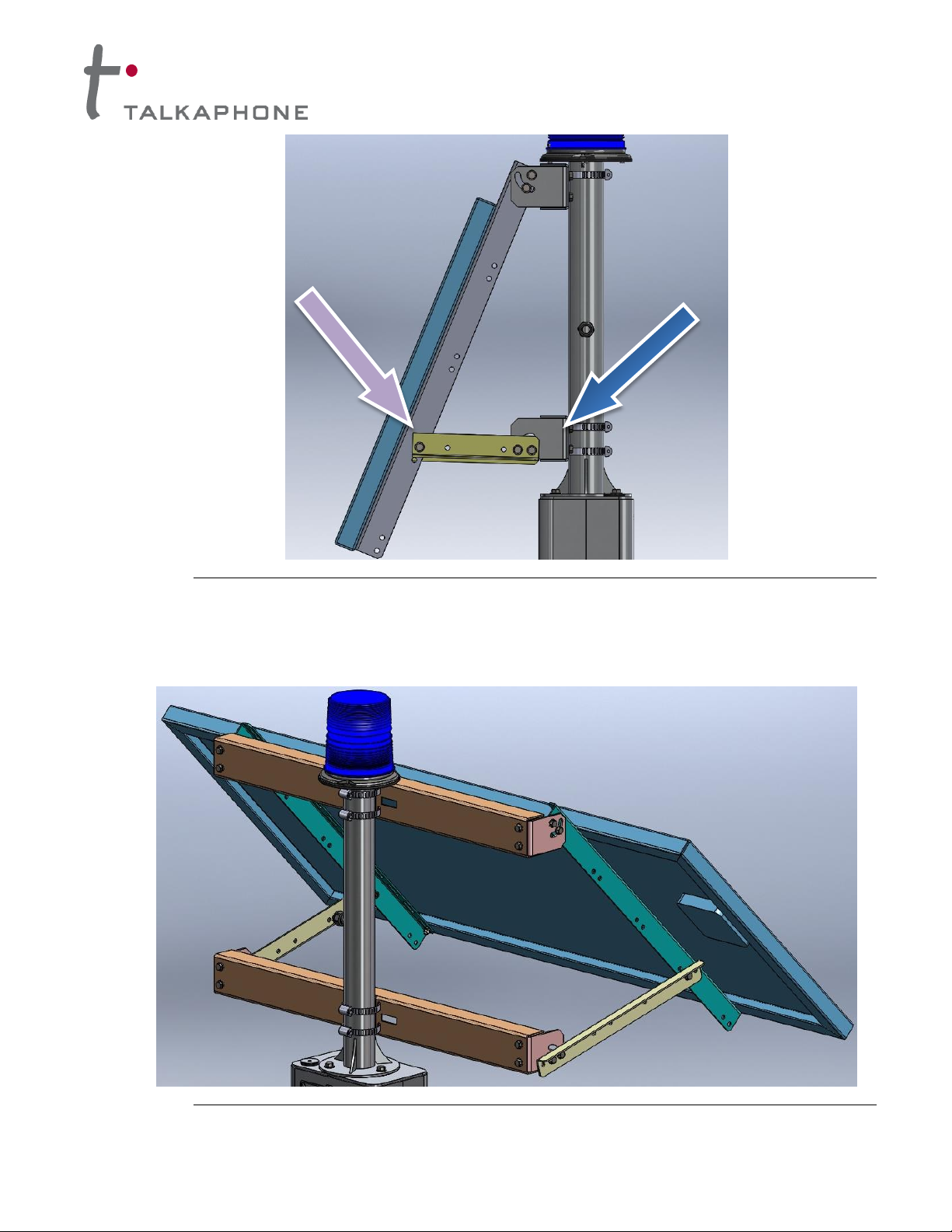
Figure 21. Support rail installation for a solar panel with a tilt angle of 55º
Figure 22. Support rail installation for a solar panel with a tilt angle of 60º
Copyright 2013 Talk-A-Phone Co. • 7530 North Natchez Avenue • Niles, Illinois 60714 • Phone 773.539.1100 • info@talkaphone.com • www.talkaphone.com. Page 13 of 25
All specifications are subject to change without notice. Talk-A-Phone is a registered trademark of Talk-A-Phone Co. All rights reserved.
Page 14
Solar Kit Installation Instructions
Figure 23. Support rail installation for a solar panel with a tilt angle of 65º
16. Once the adjustments are complete, tighten all 5/16” hardware to 12 ft-lbs as shown in Figure 24.
Figure 24. Assembled view of SLR-120-84 (shown on ETP-MTE-WP)
Copyright 2013 Talk-A-Phone Co. • 7530 North Natchez Avenue • Niles, Illinois 60714 • Phone 773.539.1100 • info@talkaphone.com • www.talkaphone.com. Page 14 of 25
All specifications are subject to change without notice. Talk-A-Phone is a registered trademark of Talk-A-Phone Co. All rights reserved.
Page 15
Solar Kit Installation Instructions
V. Mechanical Installation
1. Install the LED light board above the phone opening. To install the polycarbonate light cover that
protects the LED light assembly from the inside, peel the protective film off the light cover and fit it onto
the studs inside the tower. Slide the LED board over the studs with the LEDs facing down. The built-in
spacers will keep the LEDs from resting on the acrylic window. Tighten down using the enclosed #6
nuts. Be careful not to over-tighten to avoid cracking the circuit board.
2. If using an ETP-CI cellular device for wireless communication, install the antenna (using the respective
installation instructions) on the enclosure mount for the ETP-MTE-WP or the pole mount for the ETP-
MT/R OP SOLAR by uninstalling the hole-plug at the top of the mount. Run the power cable for the solar
panel through the liquid tight cord grip on the side of the pole.
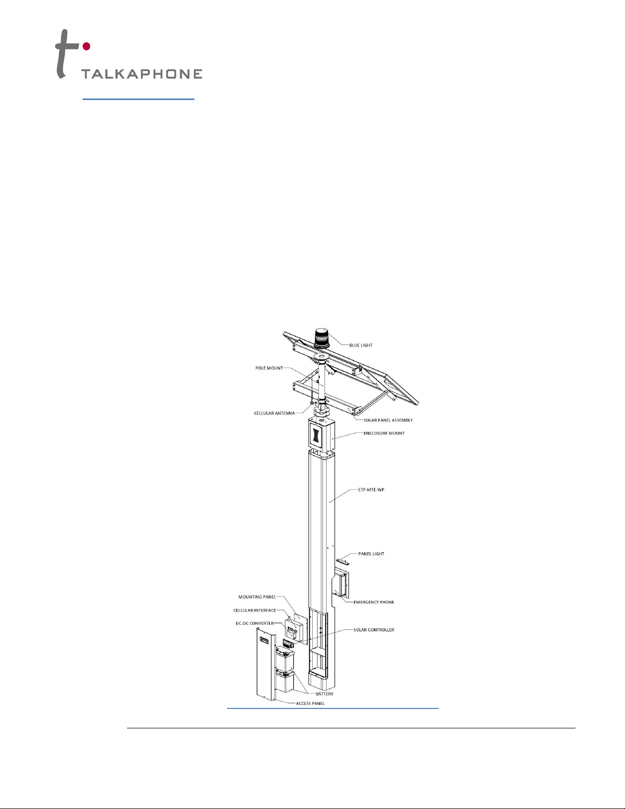
3. For ETP-MTE-WP (Refer to Figure 25),
a. Align the pole base to the center hole on top of the enclosure mount with a gasket in between.
Rotate the pole along the vertical axis to minimize the cable travel distance from the PV module
junction box and cord grip on the pole. Fasten the pole to the enclosure mount using the hex bolts
and nylon washers on the outer end and a washer and nut on the inside.
Figure 25. Exploded view of ETP-MTE-WP configuration
Copyright 2013 Talk-A-Phone Co. • 7530 North Natchez Avenue • Niles, Illinois 60714 • Phone 773.539.1100 • info@talkaphone.com • www.talkaphone.com. Page 15 of 25
All specifications are subject to change without notice. Talk-A-Phone is a registered trademark of Talk-A-Phone Co. All rights reserved.
Page 16
Solar Kit Installation Instructions
b. Fasten the LED Blue Light to the base plate on top of the pole with three (3) tamperproof screws.
Feed the power cord and control wires through the pole mount and the enclosure mount.
c. Feed the power cable and the antenna cable through the tower enclosure all the way to the bottom
of the tower. Surplus cable is used to connect the two batteries.
d. Fasten the pole mount enclosure with the solar panel and antenna attached, to the tower
e. If installing an ETP-CI cellular device for wireless communication, install the cellular interface (if
applicable) to the aluminum mounting panel by drilling two holes (for #10 screws) to align with the
keyholes behind the device. Fasten a screw through each of the drilled holes using a hex nut in
front and behind the panel. Mount the cellular device on to the heads of both screw fasteners.
f. Attach the DC-DC converter using the provided dual lock fasteners at a convenient location either
on to the tower internal sidewall or on the cellular device itself.
g. Skip to step 5.
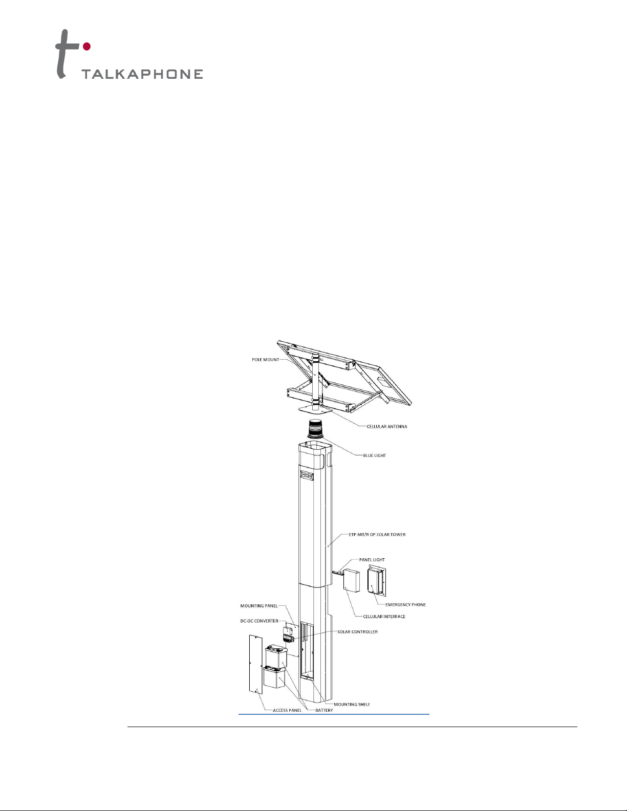
4. For ETP-MT/R OP SOLAR (Refer to Figure 26),
Figure 26. Exploded view of ETP-MT/R OP SOLAR configuration
Copyright 2013 Talk-A-Phone Co. • 7530 North Natchez Avenue • Niles, Illinois 60714 • Phone 773.539.1100 • info@talkaphone.com • www.talkaphone.com. Page 16 of 25
All specifications are subject to change without notice. Talk-A-Phone is a registered trademark of Talk-A-Phone Co. All rights reserved.
Page 17

Solar Kit Installation Instructions
a. Fasten the LED Blue Light to the base plate with three (3) tamperproof screws inside the Blue
Light housing at the top of the tower. Feed the power cord and control wires through the tower
enclosure.
b. Feed the power cable and the antenna cable through the two wire routing clips and into the hole
beneath the clips to run those cables into the tower enclosure all the way to the bottom. Extra
cable is used to connect the two batteries.
c. Fasten the pole mount with the solar panel and antenna attached, to the tower enclosure using the
tamper-resistant fasteners provided.
d. Install the cellular interface (if applicable) to the two studs behind the phone-mounting panel.
e. Mount the DC-DC Converter to the mounting panel behind the bottom access panel.
5. Install the solar controller using the included fasteners (four pan-head screws, hex nuts and washers)
to the mounting panel. This is the where most of the wiring will be connected.
VI. Electrical Installation
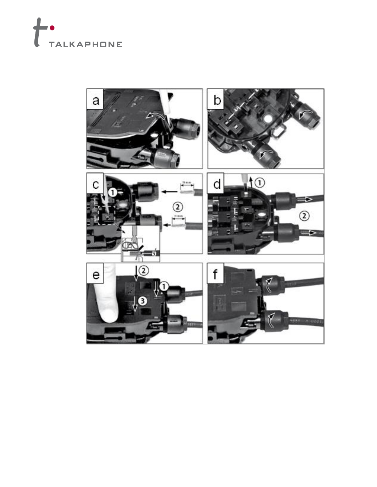
1. Connect the solar panel power cable to the junction box behind the solar panel as shown in Figure 27.
Connect the red cable to the positive terminal and the black cable to the negative terminal.
a. To open the junction box, use a screwdriver with a 9/64” wide flat head. Insert the screwdriver into
the marked opening lug. Gently unlock the lug and release the lid. Do not pull the lid out at once.
b. Open cable gland nut, if not already factory-provided.
c. Strip 0.44" of insulation from cable. Use 9/64” flat-head screwdriver to press and hold down the
terminal clamp. Push cable through the cable gland and lead it to the terminal clamp. Pay attention
to the polarity. Repeat with the second cable. Ensure the correct plug-in depth of 2.0 in for cable to
junction box.
d. Removal of the tool causes a clamping connection. Check by pulling the cable. After proper
installation the top end of cable spring is deeper compared to the middle idle cable spring.
e. After covering the box with the lid push the lid over the entire perimeter.
f. Tighten cable gland to 11.5 – 13.3 ft-lbs to ensure IP65 protection and proper tightening of the
cable.
Copyright 2013 Talk-A-Phone Co. • 7530 North Natchez Avenue • Niles, Illinois 60714 • Phone 773.539.1100 • info@talkaphone.com • www.talkaphone.com. Page 17 of 25
All specifications are subject to change without notice. Talk-A-Phone is a registered trademark of Talk-A-Phone Co. All rights reserved.
Page 18
Solar Kit Installation Instructions
Figure 27. Connecting the power cable to the solar panel junction box
2. Connect the power cable from the solar panel to the “SOLAR” terminals on the solar controller. Do not
discard excess wire. Refer to the wiring diagram as shown in Figure 28.
3. Connect the batteries in parallel to the “BATTERY” terminals on the solar controller using the excess
power cable. Crimp-on connectors are included for the batteries. Ensure that the shunt on the solar
controller is installed correctly for the battery type. Refer to the wiring diagram as shown in Figure 28.
Copyright 2013 Talk-A-Phone Co. • 7530 North Natchez Avenue • Niles, Illinois 60714 • Phone 773.539.1100 • info@talkaphone.com • www.talkaphone.com. Page 18 of 25
All specifications are subject to change without notice. Talk-A-Phone is a registered trademark of Talk-A-Phone Co. All rights reserved.
Page 19

Solar Kit Installation Instructions
Figure 28. Solar system wiring schematic
Copyright 2013 Talk-A-Phone Co. • 7530 North Natchez Avenue • Niles, Illinois 60714 • Phone 773.539.1100 • info@talkaphone.com • www.talkaphone.com. Page 19 of 25
All specifications are subject to change without notice. Talk-A-Phone is a registered trademark of Talk-A-Phone Co. All rights reserved.
Page 20

Solar Kit Installation Instructions
Connect to LOAD
Terminals on the
Solar Controller
4. The LED Blue Light (as shown in Figure 29) and LED Panel Light power wires should be connected to
the “LOAD” terminals on the controller.
Figure 29. Electrical Connections to the ETP-EL 12/24 LED Blue Light
NOTE: TOWER PTS SOLAR is shipped with ETP-EL12/24 Series Blue Light in Low Power Mode
instead of default power mode as shown in Figure 30. For Solar applications the Blue Light
must operate in Low Power Mode.
Copyright 2013 Talk-A-Phone Co. • 7530 North Natchez Avenue • Niles, Illinois 60714 • Phone 773.539.1100 • info@talkaphone.com • www.talkaphone.com. Page 20 of 25
Figure 30. Normal / Low power mode jumper inside LED Blue Light
All specifications are subject to change without notice. Talk-A-Phone is a registered trademark of Talk-A-Phone Co. All rights reserved.
Page 21

Solar Kit Installation Instructions
5. If installing an ETP-CI, connect the antenna cable to the cellular interface. Cellular interfaces should
be powered by the included DC/DC converter, which has battery ring terminals pre-connected. The
cellular interface (through the DC/DC converter) should be connected directly to the battery.
The DC-DC converter should be set to 7.5 VDC for the cellular interface device.
NOTE: If the battery voltage drops below a set threshold, the solar controller will shut off power to
the “LOAD” terminals. By connecting the emergency communication equipment directly to the
battery, emergency calls can still be placed for a small period of time after the lighting disconnects.
NOTE: Excessive drainage will damage batteries. If lights disconnect due to low voltage,
batteries must be replaced promptly to ensure correct system operation during night time hours.
6. Install the shelves and batteries in the tower’s rear lower compartment as shown in Figures 25 & 26.
Make all remaining connections, including connecting the batteries in parallel with the provided
connector cable. Refer to Figure 28
NOTE: IT IS ESSENTIAL THAT THE BATTERIES ARE CONNECTED IN PARALLEL AND NOT
IN SERIES OR SYSTEM DAMAGE WILL OCCUR.
7. When using the LED Blue Light with ETP-400 Series Emergency Phones, connect the orange and
black auxiliary control cable pair of the Blue Light to the orange and black wires of the Emergency
Phone. Plug the RJ11 connector from the emergency phone into the cellular interface.
8. Attach the Emergency Phone to the tower with six (6) 10-24 oval head tamperproof screws.
Refer to the Emergency Phone Manual and ETP-CI Instructions for information regarding the
programming of your phone.
9. A single-gang electrical box with a grounding stud is provided inside the enclosure and should be used
for grounding purposes only.
10. Re-attach the access panel cover(s).
11. Refer to Figure 31 and 32 for a fully assembled view of the ETP-MTE-WP and ETP-MT/R OP
SOLAR.
To ensure proper grounding of all electrical components, the tower enclosure should be effectively
earth grounded from the grounding stud with 6 AWG or better insulated, stranded copper wire to
the metallic power service raceway (conduit) or an 8' or longer corrosion-resistant ground spike.
Use effective drip loops on all wiring connections.
All wiring should comply with local, regional and national codes.
Copyright 2013 Talk-A-Phone Co. • 7530 North Natchez Avenue • Niles, Illinois 60714 • Phone 773.539.1100 • info@talkaphone.com • www.talkaphone.com. Page 21 of 25
All specifications are subject to change without notice. Talk-A-Phone is a registered trademark of Talk-A-Phone Co. All rights reserved.
Page 22

Solar Kit Installation Instructions
Figure 31. ETP-MTE-WP with access panel removed, assembly overview (SLR-120-84)
Copyright 2013 Talk-A-Phone Co. • 7530 North Natchez Avenue • Niles, Illinois 60714 • Phone 773.539.1100 • info@talkaphone.com • www.talkaphone.com. Page 22 of 25
All specifications are subject to change without notice. Talk-A-Phone is a registered trademark of Talk-A-Phone Co. All rights reserved.
Page 23

Solar Kit Installation Instructions
Figure 32. ETP-MT/R OP SOLAR with access panel removed, assembly overview (SLR-120-84)
Copyright 2013 Talk-A-Phone Co. • 7530 North Natchez Avenue • Niles, Illinois 60714 • Phone 773.539.1100 • info@talkaphone.com • www.talkaphone.com. Page 23 of 25
All specifications are subject to change without notice. Talk-A-Phone is a registered trademark of Talk-A-Phone Co. All rights reserved.
Page 24

Solar Kit Installation Instructions
ALABAMA
Mandalay-CA
50 Tallahassee-FL
50
Birmingham- AL
55 Moorpark-CA
55 Tampa-FL
40
Mobile-AL
55 Mount Shasta-CA
65 West Palm Beach-FL
35
Montgomery-AL
55 Needles-CA
55 GEORGIA
ALASKA
Oakland-CA
60 Atlanta-GA
55
Adak-AK
70 Palm Springs-CA
55 Augusta-GA
55
Annette-AK
75 Pardee-CA
55 Macon-GA
55
Bethel-AK
80 Point Mugu-CA
50 Savannah-GA
55
Gulkana-AK
80 Ramona-CA
55 HAWAII
Homer-AK
80 Red Bluff-CA
65 Barbers Point-HI
35
Juneau-AK
75 Redwood City-CA
60 Hilo-HI
35
King Salmon-AK
80 Rialto-CA
55 Honolulu-HI
40
Kodiak-AK
75 Richmond-CA
60 Lihue-HI
40
Matanuska-AK
80 Riverside-CA
55 IDAHO
McGrain-AK
80 Sacramento-CA
60 Boise-ID
65
Summit-AK
80 San Diego-CA
50 Kimberly-ID
65
Yakutat-AK
75 San Francisco-CA
60 Lewiston-ID
65
ARIZONA
San Luis Dam-CA
60 Pocatello-ID
65
Phoenix-AZ
55 San Rafael-CA
60 ILLINOIS
Prescott-AZ
50 Santa Maria-CA
60 Chicago-IL
65
Tucson-AZ
50 Sun Valley-CA
55 Moline-IL
65
Winslow-AZ
50 Sunnyvale-CA
60 Springfield-IL
65
Yuma-AZ
50 Victorville-CA
60 INDIANA
ARKANSA
Villa Park-CA
55 Evansville-IN
60
Fort Smith-AR
60 Visalia-CA
60 Fort Wayne-IN
65
Little Rock-AR
60 Walnut-CA
60 Indianapolis-IN
60
CALIFORNIA
Warm Sprgs Dam-CA
60 South Bend-IN
60
Alpine-CA
55 Yucca Valley-CA
55 IOWA
Arcata-CA
65 COLORADO
Burlington-IA
65
Arrowhead-CA
55 Akron-CO
55 Des Moines-IA
65
Bakersfield-CA
60 Alamosa-CO
50 Mason City-IA
65
Blythe-CA
50 Boulder-CO
60 Sioux City-IA
65
Butler Valley Ranch-CA
65 Colorado Springs-CO
55 KANSAS
Carlsbad-CA
55 Denver-CO
60 Dodge City-KS
60
Carris Plain-CA
60 Eagle-CO
65 Goodland-KS
65
Chula Vista-CA
55 Fort Collins-CO
55 Topeka-KS
65
Daggett-CA
60 Grand Junction-CO
65 Wichita-KS
60
Davis-CA
60 Pueblo-CO
55 KENTUCKY
El Cajon-CA
55 CONNECTICUT
Lexington-KY
60
El Centro-CA
45 Hartford-CT
60 Louisville-KY
60
El Segundo-CA
55 DELAWARE
LOUISIANA
El Toro-CA
55 Wilmington-DE
65 Baton Rouge-LA
55
Escondido-CA
55 DISTRICT OF COL.
Lake Charles-LA
50
Fresno-CA
60 Washington, D.C.
60 New Orleans-LA
55
Huntington Beach-CA
55 FLORIDA
Shreveport-LA
55
Inyokem-CA
60 Apalachicola-FL
55 MAINE
Jolon-CA
60 Daytona Beach-FL
45 Bangor-ME
65
Lancaster-CA
60 Jacksonville-FL
50 Caribou-ME
65
Long Beach-CA
55 Miami-FL
35 Portland-ME
65
Los Angeles-CA
55 Orlando-FL
40
Appendix A: Solar Panel Optimum Tilt Angle Table
Year-Round Non-Adjustable Installation
Copyright 2013 Talk-A-Phone Co. • 7530 North Natchez Avenue • Niles, Illinois 60714 • Phone 773.539.1100 • info@talkaphone.com • www.talkaphone.com. Page 24 of 25
All specifications are subject to change without notice. Talk-A-Phone is a registered trademark of Talk-A-Phone Co. All rights reserved.
Page 25

Solar Kit Installation Instructions
MARYLAND
NEW HAMPSHIRE
Medford-OR
65 Waco-TX
55
Baltimore-MD
60 Concorde-NH
65 North Bend-OR
65 Wichita Falls-TX
55
Patuxent River-MD
60 NEW JERSEY
Pendleton-OR
65 UTAH
MASSACHUSETTS
Lakehurst-NJ
65 Portland-OR
65 Bryce Canyon-UT
60
Blue Hill-MA
60 Newark-NJ
65 Redmond-OR
65 Cedar City-UT
65
Boston-MA
65 NEW MEXICO
Salem-OR
65 Salt Lake City-UT
65
MICHIGAN
Albuquerque-NM
55 Whitehorse Ranch-OR
65 VERMONT
Alpena-MI
65 Clayton-NM
50 PENNSYLVANIA
Burlington-VT
65
Detroit-MI
65 Farmington-NM
60 Allentown-PA
65 VIRGINIA
Flint-MI
60 Roswell-NM
50 Erie-PA
60 Norfolk-VA
60
Grand Rapids-MI
60 Truth or Conseq.-NM
45 Harrisburg-PA
65 Richmond-VA
60
Houghton-MI
65 Tucumcari-NM
50 Philadelphia-PA
65 Roanoke-VA
60
Sault St. Marie-MI
65 Zuni-NM
50 Pittsburgh-PA
60 WASHINGTON
Traverse City-MI
65 NEW YORK
Wilkes-Barre-PA
65 Olympia-WA
65
MINNESOTA
Albany-NY
65 RHODE ISLAND
Seattle-WA
65
Duluth-MN
65 Binghamton-NY
65 Providence-RI
65 Spokane-WA
70
Interna'l Falls-MN
70 Buffalo-NY
65 SOUTH CAROLINA
Whidbey Island-WA
70
Minn-St. Paul-MN
65 Massena-NY
65 Charleston-SC
55 Yakima-WA
65
Rochester-MN
65 New York City-NY
65 Columbia-SC
55 WEST VIRGINIA
MISSISSIPPI
Rochester-NY
60 Greenville-SC
60 Charleston-WV
60
Jackson-MS
55 Syracuse-NY
60 SOUTH DAKOTA
Huntington-WV
60
Meridian-MS
55 NORTH CAROLINA
Huron-SD
65 WISCONSIN
MISSOURI
Asheville-NC
60 Pierre-SD
70 Eau Claire-WI
65
Columbia-MO
60 Cape Hatteras-NC
60 Rapid City-SD
65 Green Bay-WI
65
Kansas City-MO
65 Charlotte-NC
60 Sioux Falls-SD
65 La Crosse-WI
65
Springfield-MO
60 Cherry Point-NC
55 TENNESSEE
Madison-WI
65
St. Louis-MO
60 Greensboro-NC
60 Chattanooga-TN
55 Milwaukee-WI
65
MONTANA
Raleigh-NC
60 Knoxville-TN
60 WYOMING
Billings-MT
70 NORTH DAKOTA
Memphis-TN
60 Casper-WY
70
Cut Bank-MT
70 Bismarck-ND
70 Nashville-TN
60 Cheyenne-WY
60
Dillon-MT
70 Fargo-ND
70 TEXAS
Lander-WY
65
Glasgow-MT
70 Minot-ND
70 Abilene-TX
55 Rock Springs-WY
65
Great Falls-MT
70 OHIO
Amarillo-TX
50 Sheridan-WY
70
Helena-MT
70 Akron-OH
60 Austin-TX
50
Lewiston-MT
70 Cincinnati-OH
60 Brownsville-TX
50 Miles City-MT
70 Cleveland-OH
60 Corpus Christi-TX
50
Missoula-MT
65 Columbus-OH
60 Dallas-TX
55 NEBRASKA
Dayton-OH
60 Del Rio-TX
45
Grand Island-NE
65 Toledo-OH
65 El Paso-TX
50 North Omaha-NE
65 Youngstown-OH
60 Fort Worth-TX
55
North Platte-NE
65 OKLAHOMA
Houston-TX
55 Scottsbluff-NE
65 Oklahoma City-OK
60 Kingsville-TX
50
NEVADA
Tulsa-OK
60 Laredo-TX
50 Elko-NV
65 OREGON
Lubbock-TX
50
Ely-NV
65 Astoria-OR
65 Lufkin-TX
55 Las Vegas-NV
55 Bend-OR
70 Midland-TX
50
Lovelock-NV
65 Burns-OR
65 Port Arthur-TX
55 Reno-NV
65 Eugene-OR
65 San Angelo-TX
50
Tonopah-NV
60 Hermiston-OR
65 San Antonio-TX
55
Copyright 2013 Talk-A-Phone Co. • 7530 North Natchez Avenue • Niles, Illinois 60714 • Phone 773.539.1100 • info@talkaphone.com • www.talkaphone.com. Page 25 of 25
All specifications are subject to change without notice. Talk-A-Phone is a registered trademark of Talk-A-Phone Co. All rights reserved.
 Loading...