

Page 1
ETP-GSM – Cellular Interface
Qty.
Part Number
Description
1
68696
GSM Cellular Interface
1
68416GSM
Remote-mounting Omni-directional Antenna
1
19679
Antenna Mount with Cable Assembly
1
42929
Torx T10 L-Key
2
4247
8-32 x 1/2 BH Screw
2
4248
8-32 x 5/16 Hex Nut
2
42767
#10 External Lock Washer
IMPORTANT NOTE: The ETP-GSM Cellular Interface does not comply with Enhanced 911 (E911)
requirements mandated by the Federal Communications Commission (FCC). In order to comply
with the E911 mandate, the ETP-GSM Cellular Interface software prohibits the dialing of 911.
IMPORTANT NOTE: Programming of the ETP-400 Series Phones cannot be done through a
remote call to the ETP-GSM Cellular Interface. For programming, an ETP-400 Series Phone must
be connected directly to a standard analog phone line connection.
IMPORTANT NOTE: The built-in auto-dialer of the ETP-400 Series Phone cannot dial a secondary
number in round robin fashion when used in conjunction with the ETP-GSM Cellular Interface.
IMPORTANT NOTE: All programming, diagnostics, and identification of the ETP-400 Series
Phones are accomplished through the transmitting and receiving of DTMF signals. Cellular
transmissions and cellular networks may interfere with and distort these tones. As a result of these
irregularities, model ETP-TAL Talk-A-Lert Polling may not function as intended and, therefore, may
not be appropriate in that application or environment; ETP-TAL Talk-A-Lert Base Station will not
function at all.
In any event, due to these irregularities, programming of the ETP-400 Series Phone should be done
on a land line (i.e., not through the ETP-GSM Cellular Interface.
Installation Instructions
I. Introduction
The ETP-GSM is used in conjunction with an ETP-400 Series ADA-compliant, hands-free Emergency Phone.
II. Prerequisite Cellular Service Requirements
Prior to installation and setup, the ETP-GSM Cellular Interface has the following perquisite requirements:
(1) 3G voice service from a local cellular service provider that supports GSM (e.g. AT&T, T-
Mobile);
(2) An activated SIM card provided by the local cellular service provider.
III. Contents
Before beginning installation, make sure you have all the included components. The ETP-GSM includes:
Page 1 of 10 Rev. 12/16/2014
All prices and specifications are subject to change without notice. Talk-A-Phone, Scream Alert, WEBS and WEBS Contact are registered trademarks of Talk-A-Phone Co. All rights reserved.
All other trademarks mentioned in this document or website are the property of their respective owners and does not imply or indicate any approval, endorsement, sponsorship, or affiliation
with such owners unless such approval, endorsement, sponsorship, or affiliation is expressly indicated.
Copyright 2014 Talk-A-Phone Co. • 7530 North Natchez Avenue • Niles, Illinois 60714 • Phone 773.539.1100 • info@talkaphone.com • www.talkaphone.com.
Page 2
ETP-GSM – Cellular Interface
Installation Instructions
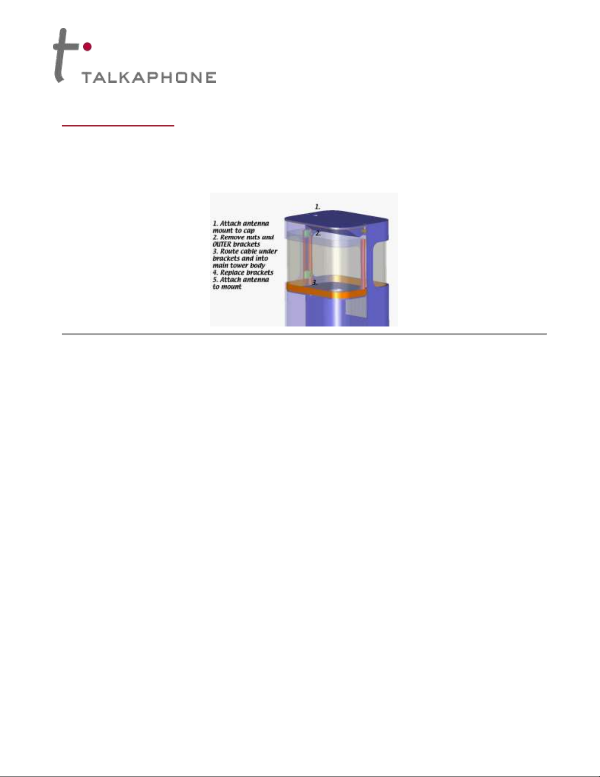
IV. Installing the Antenna
The ETP-GSM Cellular Interface includes a remote-mounting omni-directional antenna. The remote-mounting
antenna should be attached to the Talk-A-Phone enclosure (e.g. ETP-MT/R-OP-SOLAR tower) via the built-in
antenna mounting hole. To install the remote-mounting antenna, please follow the separate antenna mount
instructions included with the remote-mounting omni-directional antenna.
Figure 1. An example of mounting the remote-mounting antenna onto the cap of an ETP-MT/R-OP-PCS tower.
The remote-mounting antenna will be connected to the ETP-GSM Cellular Interface.
Page 2 of 10 Rev. 12/16/2014
All prices and specifications are subject to change without notice. Talk-A-Phone, Scream Alert, WEBS and WEBS Contact are registered trademarks of Talk-A-Phone Co. All rights reserved.
All other trademarks mentioned in this document or website are the property of their respective owners and does not imply or indicate any approval, endorsement, sponsorship, or affiliation
with such owners unless such approval, endorsement, sponsorship, or affiliation is expressly indicated.
Copyright 2014 Talk-A-Phone Co. • 7530 North Natchez Avenue • Niles, Illinois 60714 • Phone 773.539.1100 • info@talkaphone.com • www.talkaphone.com.
Page 3
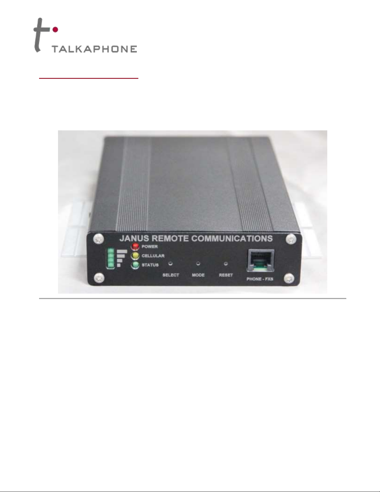
V. Installing the Cellular Interface
1. The front panel of the ETP-GSM Cellular Interface provides the following:
(1) Cellular signal strength indicator;
(2) LED indicators for POWER, CELLULAR, and STATUS;
(3) PHONE-FXS port for connecting to an ETP-400 Series Phone.
ETP-GSM – Cellular Interface
Installation Instructions
Figure 2. Front panel of the ETP-GSM Cellular Interface.
Page 3 of 10 Rev. 12/16/2014
All prices and specifications are subject to change without notice. Talk-A-Phone, Scream Alert, WEBS and WEBS Contact are registered trademarks of Talk-A-Phone Co. All rights reserved.
All other trademarks mentioned in this document or website are the property of their respective owners and does not imply or indicate any approval, endorsement, sponsorship, or affiliation
with such owners unless such approval, endorsement, sponsorship, or affiliation is expressly indicated.
Copyright 2014 Talk-A-Phone Co. • 7530 North Natchez Avenue • Niles, Illinois 60714 • Phone 773.539.1100 • info@talkaphone.com • www.talkaphone.com.
Page 4

ETP-GSM – Cellular Interface
Installation Instructions
2. The rear panel of the ETP-GSM Cellular Interface provides the following:
(1) Input terminal for 12VDC;
(2) Connector for remote-mounting omni-directional antenna;
(3) A serial port (for Talk-A-Phone Technical Support purposes only).
Figure 3. Rear panel of the ETP-GSM Cellular Interface.
3. Using the supplied Torx T10 L-Key, remove the Torx T10 screws from the rear panel (i.e. the panel with
the 12VDC, antenna, and FXS connectors).
4. Carefully slide out the electronic board from the ETP-GSM Cellular Interface chassis.
Page 4 of 10 Rev. 12/16/2014
All prices and specifications are subject to change without notice. Talk-A-Phone, Scream Alert, WEBS and WEBS Contact are registered trademarks of Talk-A-Phone Co. All rights reserved.
All other trademarks mentioned in this document or website are the property of their respective owners and does not imply or indicate any approval, endorsement, sponsorship, or affiliation
with such owners unless such approval, endorsement, sponsorship, or affiliation is expressly indicated.
Copyright 2014 Talk-A-Phone Co. • 7530 North Natchez Avenue • Niles, Illinois 60714 • Phone 773.539.1100 • info@talkaphone.com • www.talkaphone.com.
Page 5

ETP-GSM – Cellular Interface
5. Locate the SIM card holder (see Figure 4).
Installation Instructions
Figure 4. Location of the SIM card holder.
Page 5 of 10 Rev. 12/16/2014
All prices and specifications are subject to change without notice. Talk-A-Phone, Scream Alert, WEBS and WEBS Contact are registered trademarks of Talk-A-Phone Co. All rights reserved.
All other trademarks mentioned in this document or website are the property of their respective owners and does not imply or indicate any approval, endorsement, sponsorship, or affiliation
with such owners unless such approval, endorsement, sponsorship, or affiliation is expressly indicated.
Copyright 2014 Talk-A-Phone Co. • 7530 North Natchez Avenue • Niles, Illinois 60714 • Phone 773.539.1100 • info@talkaphone.com • www.talkaphone.com.
Page 6

ETP-GSM – Cellular Interface
6. Unlock the SIM card holder and flip open the tray.
Installation Instructions
Figure 5. The SIM card holder unlocked and flipped open.
Page 6 of 10 Rev. 12/16/2014
All prices and specifications are subject to change without notice. Talk-A-Phone, Scream Alert, WEBS and WEBS Contact are registered trademarks of Talk-A-Phone Co. All rights reserved.
All other trademarks mentioned in this document or website are the property of their respective owners and does not imply or indicate any approval, endorsement, sponsorship, or affiliation
with such owners unless such approval, endorsement, sponsorship, or affiliation is expressly indicated.
Copyright 2014 Talk-A-Phone Co. • 7530 North Natchez Avenue • Niles, Illinois 60714 • Phone 773.539.1100 • info@talkaphone.com • www.talkaphone.com.
Page 7

ETP-GSM – Cellular Interface
Installation Instructions
7. IMPORTANT: Note the orientation of the angled notch on both the SIM card and the SIM card holder.
Insert the SIM card into the SIM card holder according to the location of the angled notch and gold
contacts (see Figure 6).
Figure 6. The tray of the SIM card holder in the open position. Note the SIM card that has been installed into the tray.
Page 7 of 10 Rev. 12/16/2014
All prices and specifications are subject to change without notice. Talk-A-Phone, Scream Alert, WEBS and WEBS Contact are registered trademarks of Talk-A-Phone Co. All rights reserved.
All other trademarks mentioned in this document or website are the property of their respective owners and does not imply or indicate any approval, endorsement, sponsorship, or affiliation
with such owners unless such approval, endorsement, sponsorship, or affiliation is expressly indicated.
Copyright 2014 Talk-A-Phone Co. • 7530 North Natchez Avenue • Niles, Illinois 60714 • Phone 773.539.1100 • info@talkaphone.com • www.talkaphone.com.
Page 8

ETP-GSM – Cellular Interface
Installation Instructions
8. Flip the tray back to the closed position. Lock the SIM card holder by sliding the tray in the direction of
the arrow located on the tray. Figure 7 illustrates a SIM card locked into the SIM card holder.
Figure 7. SIM card installed and locked into the SIM card holder.
9. Carefully slide the electronic board back into the ETP-GSM Cellular Interface chassis.
10. Using the supplied Torx T10 L-Key, reinstall the Torx T10 screws.
11. Connect the cable assembly from the remote-mounting omni-directional antenna to the CELLULAR
connector.
12. Connect the ETP-400 Series Phone to the PHONE-FXS port.
13. If a SOLAR KIT is used, connect the LOAD terminals of the solar controller to the appropriate polarity
markings on the 12VDC input terminal (i.e. POWER terminal) of the ETP-GSM Cellular Interface.
Otherwise, connect a 12VDC power source appropriately with respect to polarity.
Page 8 of 10 Rev. 12/16/2014
All prices and specifications are subject to change without notice. Talk-A-Phone, Scream Alert, WEBS and WEBS Contact are registered trademarks of Talk-A-Phone Co. All rights reserved.
All other trademarks mentioned in this document or website are the property of their respective owners and does not imply or indicate any approval, endorsement, sponsorship, or affiliation
with such owners unless such approval, endorsement, sponsorship, or affiliation is expressly indicated.
Copyright 2014 Talk-A-Phone Co. • 7530 North Natchez Avenue • Niles, Illinois 60714 • Phone 773.539.1100 • info@talkaphone.com • www.talkaphone.com.
Page 9

ETP-GSM – Cellular Interface
Earth
12VDC
Input Terminal
Installation Instructions
14. Using the built-in mounting flanges, attach the ETP-GSM Cellular Interface onto the internal mounting
panel of the Talk-A-Phone enclosure (e.g. ETP-MT/R-OP-SOLAR). The ETP-GSM Cellular Interface
should be mounted so that the 12VDC input terminal is on the lower right corner (i.e. toward the Earth).
Page 9 of 10 Rev. 12/16/2014
All prices and specifications are subject to change without notice. Talk-A-Phone, Scream Alert, WEBS and WEBS Contact are registered trademarks of Talk-A-Phone Co. All rights reserved.
All other trademarks mentioned in this document or website are the property of their respective owners and does not imply or indicate any approval, endorsement, sponsorship, or affiliation
with such owners unless such approval, endorsement, sponsorship, or affiliation is expressly indicated.
Figure 8. This photo illustrates the appropriate mounting position and orientation for the ETP-GSM Cellular Interface.
Copyright 2014 Talk-A-Phone Co. • 7530 North Natchez Avenue • Niles, Illinois 60714 • Phone 773.539.1100 • info@talkaphone.com • www.talkaphone.com.
Page 10

ETP-GSM – Cellular Interface
Installation Instructions
VI. Activation of Cellular Service
Select a local cellular service provider that supports GSM (e.g. AT&T, T-Mobile) and 3G voice service. Per the
aforementioned installation instructions, install an activated SIM card provided by the local cellular service
provider into the ETP-GSM Cellular Interface.
VII. Programming the ETP-400 Series Phone
The ETP-400 Series Phone requires specific programming for operation with the ETP-GSM Cellular Interface.
At minimum, the ETP-400 Series Phone should be programmed with the following codes:
* 4 **
* 13 * <Phone_Number> # *
* 14 * 3 *
* 18 * 5 *
* 24 * 0 *
* 27 * 0 *
* 55 *
* 56 *
* 58 * <Speak_to_Record_Voice_Message>(optional)
* 72 *
* 103 *
For a full comprehensive list of programming codes, reference the Installation & Operation Manual for
Emergency/Information Phones.
NOTE: The hash or # appended after the <Phone_Number> (i.e. for the * 13 * <Phone_Number> # * code) is
only required if the Intelli-Voice option (V-Chip) is used on the ETP-400 Series Phone.
Page 10 of 10 Rev. 12/16/2014
All prices and specifications are subject to change without notice. Talk-A-Phone, Scream Alert, WEBS and WEBS Contact are registered trademarks of Talk-A-Phone Co. All rights reserved.
All other trademarks mentioned in this document or website are the property of their respective owners and does not imply or indicate any approval, endorsement, sponsorship, or affiliation
with such owners unless such approval, endorsement, sponsorship, or affiliation is expressly indicated.
Copyright 2014 Talk-A-Phone Co. • 7530 North Natchez Avenue • Niles, Illinois 60714 • Phone 773.539.1100 • info@talkaphone.com • www.talkaphone.com.
 Loading...