

Page 1

ETP-EL12/24 Installation Instructions
THIS PRODUCT MUST BE INSTALLED IN ACCORDANCE WITH THE
APPLICABLE INSTALLATION CODE BY A PERSON FAMILIAR WITH THE
CONSTRUCTION AND OPERATION OF THE PRODUCT AND THE HAZARDS
INVOLVED
CE PRODUIT DOIT ÊTRE INSTALLÉ SELON LE CODE D’INSTALLATION
PERTINENT, PAR UNE PERSONNE QUI CONNAÎT BIEN LES PRODUIT ET
SON FONCTIONNEMENT AINSI QUE LES RISQUES INHÉRENTS
I. Introduction
Model ETP-EL12/24 is a 12-24VDC/24VAC outdoor-rated combination blue light and strobe. The blue light is lit at
all times to draw attention to the location. The strobe can be activated by Talk-A-Phone emergency phones or by
third party devices that provide a dry contact closure or relay output. ETP-EL12/24 has a low power mode setting
for use in applications where power consumption is an important consideration.
II. Power requirements
ETP-EL12/24: 10-30VDC / 20-28VAC, 7.5 Watts, 1.5 Watts low power steady mode (18A peak inrush)
III. Mounting
If installing the blue light strobe in a Talk-A-Phone phone mount, such as an ETP-MT mounting tower, follow the
instructions included with that mount. Alternatively, remotely mount the blue light strobe to a 4” square conduit
box using an ETP-MBKT mounting bracket. Screws are included with the mount or bracket.
IV. Wiring
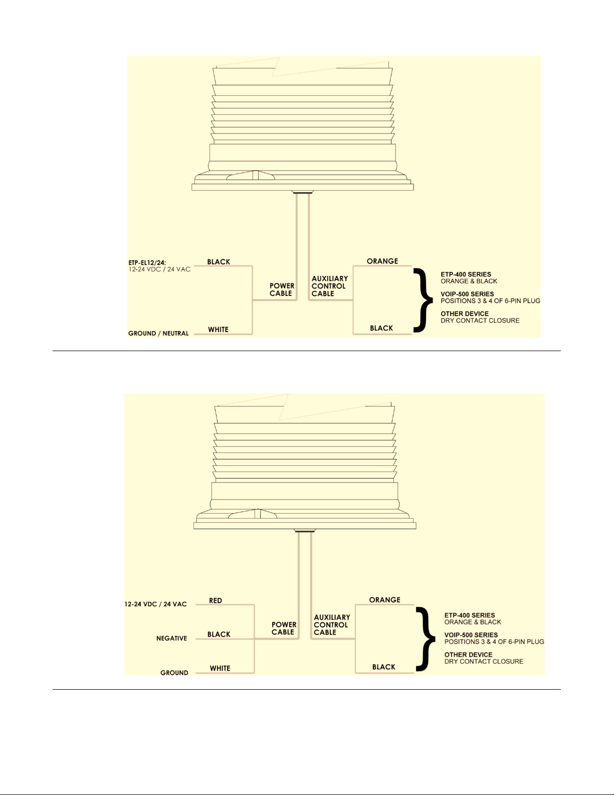
The ETP-EL12/24 blue light strobe (polycarbonate base) can be connected to either the 12-24VDC or the 24VAC
output voltage of the power source (shown in Figure 1). The ETP-EL12/24 blue light strobe (aluminum base) can
be connected to either the 12-24VDC or the 24VAC output voltage of the power source, while grounding the white
wire (shown in Figure 2).
Copyright 2010 Talk-A-Phone Co. All rights reserved.
Talk-A-Phone Co. • 7530 North Natchez Avenue • Niles, Illinois 60714-3804 Rev. 8/26/10
Phone 773.539.1100 • Fax 773.539.1241 • info@talkaphone.com • www.talkaphone.com
Specifications are subject to change without notice.
Talk-A-Phone is a registered trademark of Talk-A-Phone Co.
Page 2
ETP-EL12/24 Installation Instructions
Figure 1: Electrical connections to the ETP-EL12/24 (polycarbonate base) blue light strobes
Figure 2: Electrical connections to the ETP-EL12/24 (aluminum base) blue light strobe
Copyright 2010 Talk-A-Phone Co. All rights reserved. Page 2 of 3
Talk-A-Phone Co. • 7530 North Natchez Avenue • Niles, Illinois 60714-3804
Phone 773.539.1100 • Fax 773.539.1241 • info@talkaphone.com • www.talkaphone.com
All prices and specifications are subject to change without notice.
Talk-A-Phone is a registered trademark of Talk-A-Phone Co.
Page 3

ETP-EL12/24 Installation Instructions
When using the blue light strobe with ETP-400 Series Emergency Phones, connect the orange and black auxiliary
control cable pair of the blue light strobe to the orange and black wires of the Emergency Phone. Refer to the
Emergency Phone Manual for information regarding the programming of your phone.
When using the ETP-EL12/24 Series blue light strobe with VOIP-500 Series Emergency Phones, connect the
orange and black auxiliary control cable pair of the blue light strobe to positions 3 and 4 (Aux. Output 2) of the 6pin connector plug of the VOIP-500 Series Phone.
V. Low Power Mode
The ETP-EL12/24 blue strobe light can operate in either of the
two modes as follows:
1. Normal power mode (default mode)
2. Low power mode (power conservation mode)
For Low Power Mode:
a. Disconnect the ETP-EL12/24 blue strobe light from the
power source.
b. Untwist the Fresnel dome from the base of the ETP-
EL12/24 blue strobe light.
c. As shown in Figure 3, use the jumper to shunt the center
and the left side header positions on the 3-position
connector.
d. Fasten the Fresnel dome to the base of the ETP-EL12/24
blue strobe light and connect to the respective power
source.
Figure 3: Low power mode jumper
Copyright 2010 Talk-A-Phone Co. All rights reserved. Page 3 of 3
Talk-A-Phone Co. • 7530 North Natchez Avenue • Niles, Illinois 60714-3804
Phone 773.539.1100 • Fax 773.539.1241 • info@talkaphone.com • www.talkaphone.com
All prices and specifications are subject to change without notice.
Talk-A-Phone is a registered trademark of Talk-A-Phone Co.
 Loading...