

Page 1
Talk-A-Phone Co.
Creating Communication Solutions
Installation & Operation Manual
For EB-200 Base Station
Section
Getting Started 2
Hardware Installation 3
Programming the Base Station 4
Operation 5
FCC Information 6
Phone Line Specifications 7
Information to the User 8
Talk-A-Phone Co. Limited Warranty 9
Talk-A-Phone Co. Rev. 7-27-09
7530 North Natchez Avenue Niles, Illinois 60714-3804
Phone: (773) 539-1100 Fax: (773) 539-1241
e-mail: info@talkaphone.com http://www.talkaphone.com
All Specifications and other information are subject to change without notice. © 2009 Talk-A-Phone Co. All rights reserved.
Page
Page 2

Getting Started
I. Getting Started
A. Introduction
Thank you for your purchase of this Model EB-200 Base Station. This unit is
built with an exceptional standard of quality and should provide years of
reliable service.
This manual will guide you through the installation of this unit and provide
comprehensive operating instructions. Please read this instruction manual
COMPLETELY before you install this unit.
Once you have installed the unit and are familiar with its operation, store this
manual in an accessible location for future reference.
B. What Is In The Box
• One Base Station
• One Power Supply
• One Instruction Manual
You should inspect your Base Station when you open the box for possible
damage in shipment. If it is damaged, or any of the components are missing,
contact your Talk-A-Phone Co. distributor immediately. Do not discard any
hardware or packing material before you are certain you have all the items
listed above, and the unit is installed and functioning correctly.
C. Technical Requirements
In order to report an incoming Emergency Phone call, the EB-200 must "hear"
the DTMF tones that are transmitted by all Talk-A-Phone Emergency Phones.
For most applications, the Base Station will be in series with the phone line so
that it will automatically hear the tones as soon as the incoming call is
answered. However, in certain applications, the EB-200 will be connected in
parallel with the phone handset. In this case, be sure that the volume is not
turned down on the handset or the EB-200 will not detect an incoming call.
Any significant noise on the telephone line will also interfere with the
functioning of the EB-200.
If you are planning on connecting the EB-200 to a digital phone line, be sure to
read the Special Instructions for Using a Digital Phone Line.
You will need a serial cable to connect the EB-200 to a serial printer. If you
purchase the Talk-A-Phone model EB-P1 Palm Printer, a serial cable is
included.
Page 3
II. Hardware Installation
A. Connecting the Base Station
Plug the RJ11 male connector from the incoming phone line into the RJ11
connector marked "Line" on the rear of the Base Station. Plug the RJ11 male
connector on the phone cable coming from the guard or attendant phone into
the RJ11 female connector marked "Phone" on the rear of the Base Station.
B. Connecting the Power Supply
Plug the cable with the male jack extending from the Power Supply into the
female power receptacle marked "POWER" on the rear of the Base Station.
Now plug the Power Supply into a 120 volt 50-60 Hz AC Electrical outlet.
LED's in the ID Number Section on the front of the Base Station will light with
dashes to show that power is being supplied.
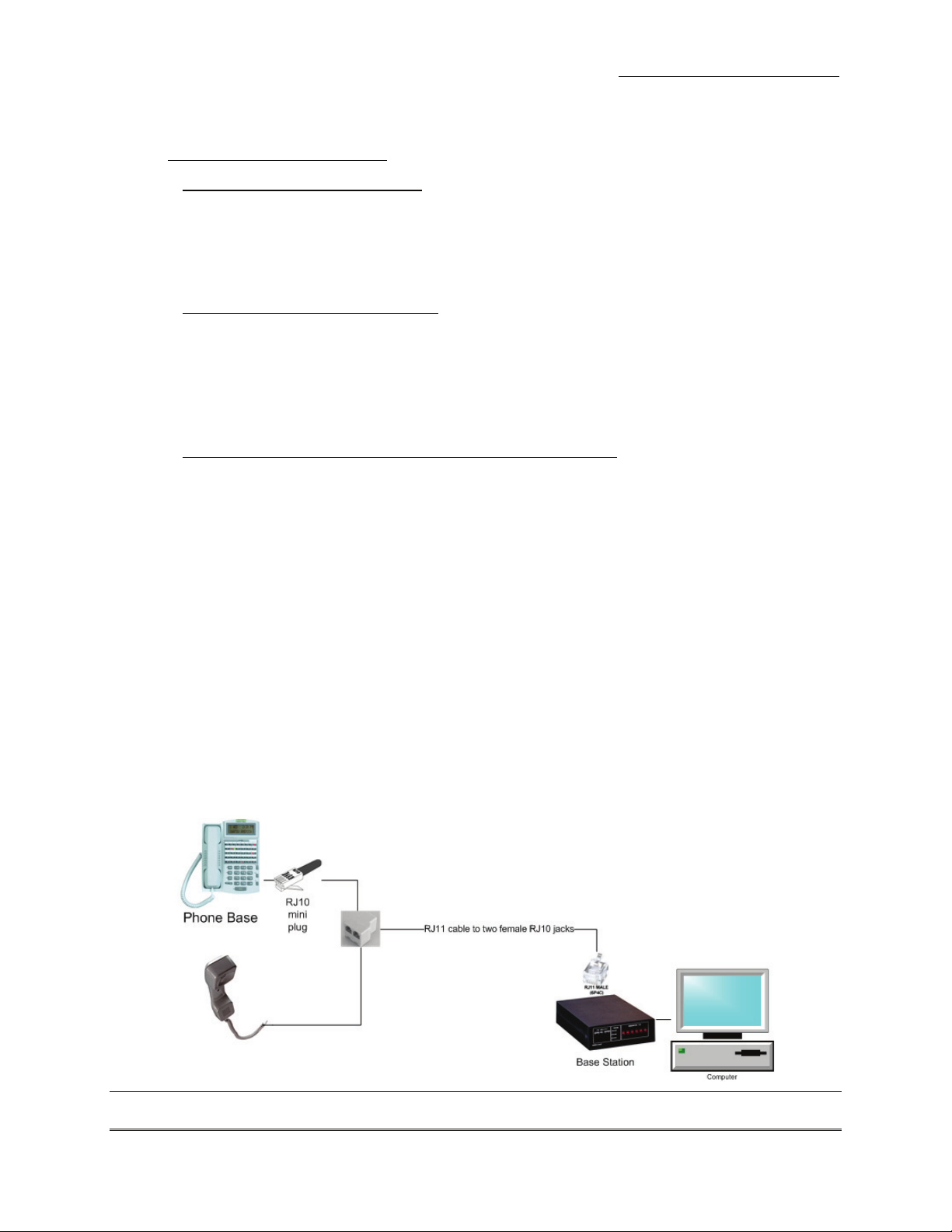
C. Special Instructions for Using a Digital Phone Line
If you are using a digital phone line, you must connect the Base Station in
parallel with the phone handset using the included splitter cable (see Figure 1).
1. Plug the included male RJ11 splitter into the LINE port in the Base Station.
2. Unplug the RJ10 phone cord from your digital phone base and plug it into
one of the female ports on the included RJ11 splitter.
3. Plug another RJ10 cord into the second port of the splitter with the other
end going into the handset.
4. The splitter will allow the EB-200 to capture the DTMF tones, but will
reduce the volume of the handset as well as the EB-200 base station. For
proper functionality of Talk-A-Lert, the handset volume MUST BE SET TO
MAXIMUM. Please program the attendant phone station to the highest
volume setting. If you are using the EB-200 in conjunction with a Talk-APhone/Iwatsu PBX system, please call Talk-A-Phone’s Technical Support
line at (773) 539-1100.
5. Once the rest of the installation is complete, test out the EB-200 to see if the
LED's light when you receive a call.
Hardware Installation
Figure 1. Connecting the Base Station to a digital phone handset
Talk-A-Phone Co. Page 3 of 9
Page 4

Programming the Base Station
D. Connecting a Printer
Connect a serial printer to the SERIAL port on the Base Station. Make sure the
printer has paper and is provided with power. If you are using model EB-P1
Palm Printer, be sure to feed the paper spool through the lower slot and
advance the paper. The LED should be lit to indicate that the unit is receiving
power.
III. Programming the Base Station
If the EB-200 Base Station is attached to a serial port printer, you will want to
program the Base Station to meet the specifications of the printer and with the
other data that will automatically print out with each call.
To program the Base Station, make sure all the connections described in the
previous steps are complete, then call the phone that the Base Station is
connected to. Answer the call and begin programming by entering the
commands on the keypad of the calling phone according to the following chart:
Page 5

Programming Commands
Setting Serial Printer Baud Rate:
Enter *2XXXXY
Setting Base Station ID
*6XXXXXX
Setting The Date
*7MMDDYY
Setting The Time
*8HHMMSSD
(Note: defaults are pre-set for EB-P1 Palm Printer)
XXXX = 0300 for 300 baud
XXXX = 0600 for 600 baud
XXXX = 1200 for 1200 baud (default)
XXXX = 2400 for 2400 baud
XXXX = anything else, "OOPS" will be displayed.
Y = 1 to ignore CTS (clear-to-send from the printer)
Y = 0 sets CTS to high (default)
Y = anything else, "OOPS" will be displayed.
Set the 6 digit Base Station ID if multiple Base
Stations are in use
MM = month 01-12
DD = date 01-31
YY = year 00-99
HH = hour 00-23 (military time)
MM = minute 00-59
SS = second 00-59
D = day of the week 1-7 (1 = Sunday)
IV. Operation
Operation
When a call is received from an Emergency Phone or an Emergency Phone is
called from the phone that is connected to the Base Station, the 6-digit
identification number that has been programmed into the Emergency Phone will
display in the ID Number Section on the front of the Base Station Unit. A code
entered as "1" would be displayed as "000001". For more information on
programming the Emergency Phone's ID code, see page 10 of the Emergency
Phone Manual.
In addition, the EB-200 will indicate which button was pushed on a 2-button
Emergency Phone (button 1 is the top button, usually EMERGENCY), if an
Auxiliary Input was used to activate the phone in lieu of pressing a button and if
either of the Auxiliary Outputs were activated (displayed as AUX's 2 and 3).
If a serial printer is connected and the Base Station is properly programmed, the
6 digit ID will be printed along with the date, time, and Base Station ID.
Note: If a transmission problem affects the reporting of data (such as talking over
the DTMF tones or noise on the line), dashes will appear in the ID number
section of the Base Station instead of the ID number. You can have the ID
Number automatically resent to the Base Station by first holding down the
* button on your telephone for 1 second (you should hear one beep, if not
try again),then entering *9* on your telephone. Do not speak into the
telephone while re-reporting is in progress.
Talk-A-Phone Co. Page 5 of 9
Page 6

FCC Information
V. Federal Communications Commission Information
This device has been granted a registration number by the Federal Communications Commission
(FCC), under part 8 rules and regulations for direct connection to telephone lines. In order to
comply with these FCC rules, the following instructions must be carefully read and applicable
portions followed completely. These instructions must be provided to the consumer.
A. This equipment complies with part 68 of the FCC rules. A label located on an outside surface
of this equipment contains, among other information, the FCC registration number and ringer
equivalence number (REN). If requested, this information must be provided to the Telephone
Company.
B. As indicated below, the suitable jack (USOC connecting arrangement) for this equipment is
shown. If applicable, the facility interface codes (FIC) and service order codes (SOC) are
shown.
C. The ringer equivalence number (REN) is used to determine the quantity of devices which,
when connected to the telephone line, may result in the device not ringing in response to an
incoming call. In most, but not all, areas, the sum of the REN’s should not exceed five (5.0). To
be certain of the maximum number of devices that may be connected to the line, as determined
by the total REN’s, contact the Telephone Company to determine the maximum REN for the
calling area.
D. If this equipment (indicated with trade name and model) causes harm to the Telephone
Network, the Telephone Company will notify you in advance. If advance notice is not
practical, the Telephone Company will notify the customer as soon as possible. Also, you will
be advised of your right to file a complaint with the FCC if you believe it is necessary.
E. The Telephone Company may make changes to its facilities, equipment, operations or
procedures that could affect the operation of this equipment. If this happens, the Telephone
Company will provide advance notice in order for you to make the necessary modifications
needed in order to maintain uninterrupted service.
F. If trouble is experienced with this equipment, (indicated below with trade name and model,
together with a service center in the U. S. A. address and telephone number), contact the
manufacturer for repair and/or warranty information. If the trouble is causing harm to the
Telephone Network, the Telephone Company may request that you remove the equipment
from the Network until the problem is resolved. User repairs must not be made. Doing so
voids the warranty.
G. This equipment must not be used on Telephone Company provided public coin service.
Connection to party lines is subject to State Tariffs, (contact your State Public Utility
Commission for information). If so required, this equipment is hearing aid compatible (HAC).
H. The user is cautioned that any changes or modifications not expressly approved by the party
responsible for compliance could void the user’s authority to operate the equipment.
I. The Talk-A-Phone Co. U. S. A. Service Center is located at 7530 North Natchez Avenue, Niles,
IL 60714-3804, telephone number (773) 539-1100, fax number (773) 539-1241.
Page 7

VI. Phone Line Specifications
A. MODE I Operation
The following criteria must be met by a phone line to insure proper functionality of the FCC
approved equipment. All voltages use Tip as ground when measuring.
1. On-Hook voltage must be less than or equal to –36 V (-50 V standard).
2. Off-Hook should be recognized in a maximum time of 300 ms.
3. At an Off-Hook voltage of –15 V, the current that is supplied must be no less than 20 mA
and no more than 120 mA.
4. Dial tone must consist of 350 Hz and 450 Hz tones at –17 dB ± 0.5%.
5. The telephone line must generate Ring-Back consisting of 440 Hz and 480 Hz tones at –17
dB ± 0.5%, with a duty cycle of 1.6 seconds on—4.8 seconds off ± 10% interrupted at 20 Hz.
6. The telephone line must generate a busy signal consisting of 480 Hz and 620 Hz tones at –
17 dB ± 0.5%, with a duty cycle of 500 ms on—500 ms off.
7. The telephone line must be able to recognize or send the following frequencies in order to
decode or transmit DTMF:
a) 685 Hz — 709 Hz Row 1
b) 757 Hz — 784 Hz Row 2
c) 837 Hz — 867 Hz Row 3
d) 925 Hz —957 Hz Row 4
e) 1189 Hz — 1229 Hz Column 1 (1, 4, 7, *)
f) 1314 Hz — 1358 Hz Column 2 (2, 5, 8, 0)
g) 1453 Hz — 1501 Hz Column 3 (3, 6, 9, #)
h) 1607 Hz — 1659 Hz Column 4 (A, B, C, D)
8. When dialing, the telephone line should require a minimum tone pulse ON time of 40 ms,
as well as a minimum between tone gap of 40 ms.
9. The telephone line should support and match with a 600 AC impedance, as well as a DC
resistance of 100 — 200 .
B. MODE II and MODE III Operation
Talk-A-Phone phones can be used with most PBX systems with non-standard dial tones,
ring-backs, busy signals and hang-ups.
Phone Line Specifications
Talk-A-Phone Co. Page 7 of 9
Page 8

Information to the User
VII. Information To The User
A. Section 15.105
This equipment has been tested and found to comply with the limits for a Class B Digital
Device, pursuant to Part 15 of the FCC rules. These limits are designed to provide reasonable
protection against harmful interference in a residential installation. This equipment generates,
uses and can radiate radio frequency energy, and may cause harmful interference to radio
communications if not installed and used in accordance to the instructions. However, there is
no guarantee that the interference will not occur in a particular installation. If this equipment
does cause harmful interference to radio or television reception, which can be determined by
turning the equipment off and on, the user is encouraged to try to correct the interference by
one or more of the following measures:
1. Reorient or relocate the receiving antenna;
2. Increase the distance between the equipment and the receiver;
3. Connect the equipment into an outlet on a circuit different from that to which the receiver
is connected;
4. Consult the dealer or an experienced Radio/TV technician for assistance.
B. Section 15.21
The user is cautioned that any changes or modifications not expressly approved by the party
responsible for compliance could void the user’s authority to operate the equipment.
C. Section 15.27
The user is cautioned that any peripheral device installed with this equipment, such as a
modem or printer, must be connected with a high-quality shielded cable to insure compliance
with FCC limits.
D. Talk-A-Phone Factory Service
Talk-A-Phone factory service is available to Talk-A-Phone users at a reasonable charge, plus
transportation to and from our factory. When you send units to our factory, freight prepaid,
our technicians will examine, service and promptly return the units to you, transportation
collect.
You must receive a Return Materials Authorization (RMA) number to send units in for
repair. Contact the Talk-A-Phone Service department for more information.
Talk-A-Phone also sells replacement components for our products directly both to dealers and
to our users. When ordering, please give either the component part number or a brief
description of the component’s function, and the model for which it is needed.
When returning equipment for service or ordering replacement components, please se sure to
include your full name, address and telephone number.
Page 9

Talk-A-Phone Limited Warranty
VIII. Talk-A-Phone Co. Limited Warranty
Talk-A-Phone Co. warrants Talk-A-Phone equipment against any defects in
material and workmanship, under normal use, for a period of twelve (12) months
from date of installation, provided that Talk-A-Phone receives a completed
"Installation Certification" certifying the date on which the system has been
installed. An "Installation Certification" card is enclosed with every unit. In the
event that no "Installation Certification" is received by Talk-A-Phone, the twelve
(12) months will commence on the date of shipment by Talk-A-Phone. The
warranty period for Models ETP-PM, ETP-MT and ETP-MT/R is five (5) years,
under the same terms and conditions.
In the event this product is found by Talk-A-Phone to be defective within the
warranty period, Talk-A-Phone's only obligation and your exclusive remedy
shall be the repair and/or replacement of any defective parts, provided the
equipment is returned to Talk-A-Phone Co., 7530 North Natchez Avenue, Niles,
IIL 60714. It is expressly understood that Talk-A-Phone shall have no obligation
to furnish labor, nor pay for the labor of any third parties, nor bear the expense
of shipping defective products for repair. This warranty shall not apply if
Talk-A-Phone determines that the defect was caused by improper use or
installation, or damage caused to the equipment by others.
THIS WARRANTY GIVES YOU SPECIFIC LEGAL RIGHTS AND YOU MAY
ALSO HAVE OTHER RIGHTS WHICH VARY FROM STATE TO STATE.
Talk-A-Phone Co. Page 9 of 9
 Loading...