


ISRAEL
TALGIL COMPUTING & CONTROL LTD.
NAAMAN CENTER, HAIFA - ACCO ROAD 7000
P.O.BOX 775 KIRYAT MOTZKIN 26119, ISRAEL
TEL: 972-4-8775947; 972-4-8775948
FAX: 972-4-8775949
E-mail: talgil33@netvision.net.il
FILTRON
1-10 (DC/AC)
U S E R ' S M A N U A L
2011
TALGIL
Computing & Control Ltd.
1
FILTRON 1-10 (DC/AC)
List of features
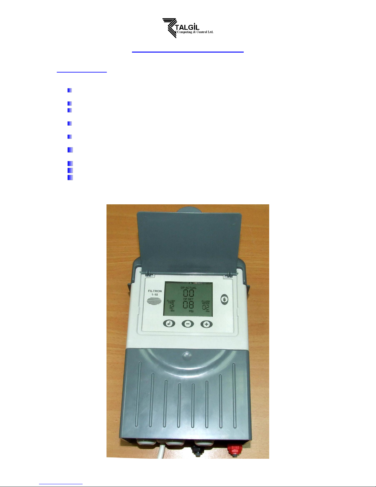
The “FILTRON 1-10” is a modular backflushing controller for automatic filters of 1 to 10
stations.
There exist DC and AC models.
The DC model can be powered either by 6v DC or 12v DC and it activates 2 wired 12v DC
latching solenoids. The voltage for the solenoids switching is boosted by a charge pump.
The AC model contains an internal transformer that can be powered by 110v or 220v from
which it generates the 24v AC for the solenoids.
Flushing cycles may be triggered either by time or by the embedded electronic DP sensor
reaching the set point, or by a dry contact signal from an external DP sensor.
Endless looping problems can be eliminated by detecting repeated consecutive cycles
passing beyond a predefined limit.
The unit can optionally handle a Pressure-Sustaining / Main valve, and an Alarm output.
The unit is equipped with a customized LCD display and key board.
The unit counts separately the number of flushing cycles triggered by DP, by time and
manually.
2
How to program the controller
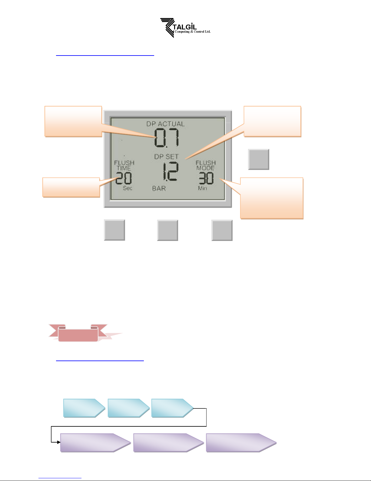
The controller is equipped with an LCD display and 4 keys as displayed below. When the unit is left
untouched for a minute the display is switched off and the only life signal is given by a beep sound that
can be heard every 20 seconds. Holding down any of the keys for a few seconds will bring the screen
back to life.
ENTER
+-
MANUAL
The screen consists of several fields, some of them are editable and some of them are not. For
inserting EDIT MODE the ENTER key has to be pushed. The EDIT MODE is indicated by blinking of
the characters at the currently editable field. Each time the ENTER key is pushed again, the next
editable field becomes under focus and starts blinking. While in EDIT MODE the “+” and “-“ keys can
be used for changing the value under focus. Pushing the ENTER key again will set the selected value
to the current field and move the focus to the next editable field which will start blinking. Once entering
this process of passing through the editable fields, the user has no way back but by pushing the
ENTER key repeatedly, he passes through the chain of editable fields until arriving back to the FLUSH
TIME field, meeting no more blinking fields.
Notice that before the first use of the unit, it may be necessary to pass through
the configuration process prior to defining the flushing program in order to
adjust the features of controller to the specific application. The configuration
process is described below.
The chain of editable fields
Following is the chain of editable fields. The existence of the DP SET-POINT field depends on whether
the system contains a built-in electronic DP or not.
The Actual DP value.
Available only when
the built in electronic
DP is used
The DP Set-Point.
Available only when
the built in electronic
DP is used
The desired flushing
time per station
The desired flushing
mode. Contains either the
flushing interval or the
letters “dp” when the
flushing is triggered by
dp only.
FLUSH
TIME
DP SETPOINT
FLUSH
MODE
ACCUMULATIONS
DP
ACCUMULATIONS
TIME
ACCUMULATIONS
MANUAL
REMARK

3
The Flush Time
Defines the duration of the flushing time per station. The following options are selectable:
5-20 sec in steps of 1 sec
20-55 sec in steps of 5 sec
1-6 min in steps of 0.5 min
The DP Set Point
At this field the user defines the pressure difference between the filter’s inlet and outlet that when
reached, a flushing cycle will take place. This field is meaningless when electronic DP sensor is not in
use, therefore the user is expected to define the DP set point to be 00, as a result the actual DP value
will appear as (- -).
When the pressure is expressed in BAR the range of values is 0.1 – 2.0 BAR.
When the pressure is expressed in PSI the range of values is 1- 30 PSI.
When the system does not include the built in electronic DP sensor but uses instead an external DP
sensor, the flushing request signal arrives in the shape of a closed dry contact at the appropriate input
terminals.
The Flush Mode
The Flush Mode defines how the flushing cycles is triggered. The selectable options are as follows:
OFF - no flushing will take place
By time – In this case the flushing cycles will be repeated in a selected interval or will be triggered
by the DP signal depending on what happens first. No matter how was the flushing
cycle started the interval to the next cycle will start to be measured again after each
ending of a flushing sequence. The selectable intervals are the following:
5, 10, 15, 20, 25, 30, 35, 40, 45, 50, 55, 60 minutes
2, 3, 4, 5, 6, 8, 12, 18, 24, 72, 120 hours
dp – flushing will be triggered by DP only.
If the “+” and “-“ keys are pressed and held down simultaneously the
“Flush Mode” field will show the left time until next cycle, alternately hours
and minutes.
The Accumulations
The unit accumulates and displays the number of flushing cycles caused by DP, by time, or manually
At each of the accumulation fields, the “+” or “-“ keys may be used for clearing the accumulated value.
The Configuration
In order to enter into the configuration process press and hold down the ENTER key for at least 3
seconds.
REMARK

4
The unit will detect how many “plug-in” boards (each of 2 outputs) are used in the particular case.
How will the outputs be allocated depends on the definitions made during the configuration process
described below. The following rules apply:
1. Backflush valves will be allocated starting from output 1 and up.
2. The last backflush valve can be canceled and then its allocated output will be left
unused.
3. Alarm output, Delay-Valve and Main-Valve when defined, will be allocated in this order,
right after the last backflush valve (whether in use or not).
Example:
Assuming there are 3 “plug-in” boards, this makes 6 outputs for use. If there are no Alarm-output, no
Delay-Valve and no Main-Valve all the 6 outputs will be allocated for backflush valves.
If additionally a Main-Valve is defined, the first 5 outputs will be allocated for backflush valves and
output No 6 for the Main-Valve. Output No 5 (of the last backflush valve) can be canceled and left
unused. If additionally a Delay-Valve is defined it will be allocated to output 5 right before the Main
valve, leaving the first 4 outputs for backflush valves, and once again output No 4 (of the last backflush
valve) can be canceled and left unused. If additionally an Alarm-output is defined it will be allocated
before the Delay-Valve leaving only 3 of the first outputs for backflush valves. No 3 can again be
canceled.
During the configuration process the following features are defined:
Main Valve (sustaining valve) - Yes/ No. W hen the answer is “Yes” the Pre Dwell delay between the
Main Valve opening and the opening of Station No. 1 can be defined.
The selectable delay steps are:
5, 10, 15, 20, 25, 30, 35, 40, 45, 50, 55 sec
1, 1.5, 2, 2.5, 3, 3.5, 4, 4.5, 5, 5.5, 6 min
Dwell time - the delay between stations – can be set to 5, 10, 15, 20, 25, 30, 35,
40, 45, 50, 55, or 60 sec.
DP delay - the delay during which the DP sensor reading is expected to remain
stable before reaction – 5, 10, 15, 20, 25, 30, 35, 40, 45, 50, 55, 60
sec.
Looping limit - the number of consecutive flushing cycles triggered by the DP sensor
before deciding that there is an endless looping problem. The options
are: 1-10 or “no” which means ignoring the looping problem.
Alarm - Yes/No – allocating one output for alarm activation.
Delay Valve - Yes/No – allocating an output for Delay Valve activation.
View Outputs - this is a special mode that enables passing through the list of outputs
to see how each output was allocated. Use the + key to change the
“no” into “yes” and confirm by “Enter”, then keep using the + key to
pass through the list. At the bottom left corner the ordinal number of
the output is displayed and its allocated function appears in large
letters at the center of the screen. Notice that the number of possible
outputs that can be used is always an even number since it results
from the number of “plug in” boards (each of 2 outputs) included.
However if the number of outputs needed is not an even number,
then the last valve allocated for flushing may be canceled by use of
the manual operations key.
Pressure units - deciding about the units to be used for pressure measurement.
Selecting between BAR or PSI .
Calibration- Zero calibration of the built in electronic DP sensor. While the sensor
ports are disconnected select Calibration = Yes.
Version display- The last screen of the configuration supplies information about the
software version of the controller. the version consists of 4 digits like
the following:
00
13

5
Handling Endless Looping problems
As explained above, endless looping problem will be declared when the number of consecutive
flushing cycles triggered by the DP sensor exceeds the “Looping limit” defined during configuration.
The fact that endless looping problem was detected will be indicated on the display and will cause the
activation of the Alarm output, additionally, the DP indication will no longer be considered as a trigger
for flushing. The following flushing cycles will be triggered by the interval count down only.
The problem will be considered as solved when the constant indication of the DP sensor will be
removed.
Handling Low pressure
When a closed contact indication is received at the low pressure input of the controller, the symbol
will start to appear blinking at the display. All activities will stop including the countdown to the next
flushing cycle. If the low pressure happened while a flushing sequence was in progress, when the low
pressure condition terminates the flushing sequence will start from the beginning rather than continue
from the stop point.
Connecting the DP sensor to the filter system
The DP sensor is connected to the filter system by 2 command tubes, the
one which comes from the filter inlet (High pressure) will be connected to
the red point, and the one that comes from the outlet (Lower pressure) will
go to the black point. It is important to put a small filter of 120 mesh (not
supplied) between the red point and the high pressure connection point.
Low battery
The unit has two levels of low battery indication. At the first level when the battery voltage drops to the
first level, the sign will start to appear at the screen. When the battery voltage drops further and
reaches the second level, all outputs will shut down, the screen will be cleared leaving only the low
battery icon.
Manual activation
A flushing sequence can be manually activated by the “MANUAL” key. When manually activated the
icon will appear on the display. The same key will be used for manually terminating a sequence
in progress.
The small filter to be added between the high
pressure inlet and the red point. It is the user’s
responsibility to add this filter.

6
Main valve
Valve 1
Valve 2
Pre
Dwell
Flush time
Valve 3
Valve 4
Dwell
time
Main valve
Valve 1
Valve 2
Pre
Dwell
Flush time
Valve 3
Valve 4
Delay valve
Dwell
time
V V
Valve
Delay
Timing Diagram
Without Delay Valve
Including Delay Valve

7
Wiring Diagram
DC MODEL
The drawing below shows the wiring of the DC model of the controller.
Notice that:
1. The External DP sensor is optional and it is intended for use in cases there is no
Embedded Electronic DP included.
2. The powering of the unit can be either by 6v DC or 12v DC.
3. The solenoids will be of 12VDC latch.
Make sure to DISCONNECT the
POWER before inserting / removing
the 2 ouputs plug-in unit.

8
AC MODEL
The drawing below shows the wiring of the AC model of the controller.
Notice that:
1. The External DP sensor is optional and it is intended for use in cases there is no
Embedded Electronic DP included.
2. The powering of the unit is by 24VAC transformed from 220/110 VAC.
3. The solenoids will be of 24VAC.
Make sure to DISCONNECT the
POWER before inserting / removing
the 2 ouputs plug-in unit.

9
TECHNICAL DATA
DC MODEL
Power source: 6v supplied by 4 x 1.5 “D” size alkaline batteries.
or 12v DC dry battery
or 12v rechargeable battery with solar panel of 2 watts
Outputs : 12v DC latching solenoids.
DP: Embedded electronic analog DP sensor
or external dry contact DP sensor.
Pressure Sensor: Dry contact pressure sensor
Operating temperature: 0-60 C.
AC MODEL
Power source: 220 or 110 v AC 50 or 60 Hz with built in transformer to 24v AC.
Outputs : 24v AC solenoids.
DP: Embedded electronic analog DP sensor
or external dry contact DP sensor.
Pressure Sensor: Dry contact pressure sensor
Operating temperature: 0-60 C.
 Loading...