

Page 1
TX-114TR/114FR/114SR
DUAL ZONE OUTDOOR PIR / Instruction Manual
PIR EXTERIOR DE ZONA DUAL / Manual de instrucciones
1
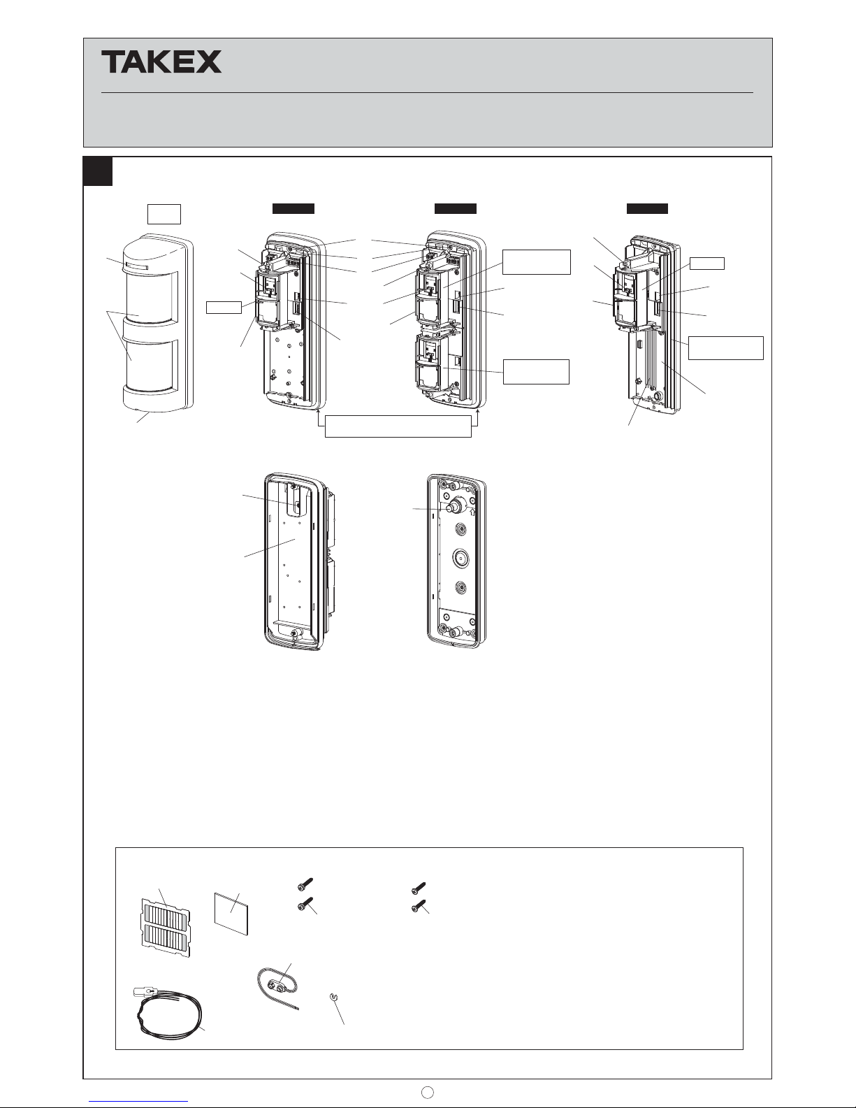
Accessories Accesorios
P (1 pc, 1 pza.)
U (1 pc, 1 pza.)
S (1 pc, 1 pza.)
Q TX-114TR/114FR
(2 pcs, 2 pzas.)
R TX-114SR
(1 pc, 1 pza.)
O
TX-114TR/114SR (1 pc, 1 pza.)
TX-114FR (2 pcs, 2 pzas.)
Sensor
Cover
Tapa
Body unit + Mounting base
Unidad del cuerpo + Base de montaje
Upper Sensor
Sensor superior
Lower Sensor
Sensor inferior
A
D
F
G
H
I
J
D
A
M
N
K
I
I
J
E
E
B
C
TX-114TR
TX-114FR TX-114SR
Sensor
Body unit
Unidad del cuerpo
Mounting base
Base de montaje
A
J
K
L
D
E
A
Body unit
Unidad del cuerpo
O. Area masking sheet
Lámina de enmascaramiento de área
P. Adhesive sheet
Lámina adhesiva
Q. Mounting screw with seal W
Tornillo de montaje con sello W
R. Mounting screw
Tornillo de montaje
S. Battery holder
Soporte de batería
T. Battery Leads
Cables para la batería
U. Back Tamper killer
Tamper trasero killer
A. Operation LED
LED operacional
B. Lens
Lente
C. Cover locking screw
Tornillo de bloqueo de la tapa
D. Adjustment lever
Palanca de ajuste
E. Sensitivity adjustment
Ajuste de sensibilidad
F. Body locking screw
Tornillo de bloqueo del cuerpo
G. Wiring hole
Orificio del cableado
H. Terminals
Terminales
I. Front tamper switch
Interruptor tamper frontal
J. Setting switches
Interruptores de ajuste
K. Space for battery & transmitter
Espacio para la batería y el transmisor
L. Wire color
Red : Battery input (+)
Black : Battery input (-)
Blue : Alarm signal
Green : Tamper signal
Color del cable
Rojo : Entrada de la batería (+)
Negro : Salida de la batería (-)
Azul : Señal de alarma
Verde : Señal tamper
M. Back tamper switch
Interruptor tamper trasero
N. Back tamper actuator
Actuador tamper trasero
T (2 pcs, 2 pzas.)
1
PARTS DESCRIPTION DESCRIPCIÓN DE LAS PIEZAS
Page 2
3
DETECTION AREA ZONA DE DETECCIÓN
2
Detection distance
Distancia de detección
Detection distance
Distancia de detección
Detection distance
Distancia de detección
Horizontal Zone
Zona horizontal
Downward Zone
Zona baja
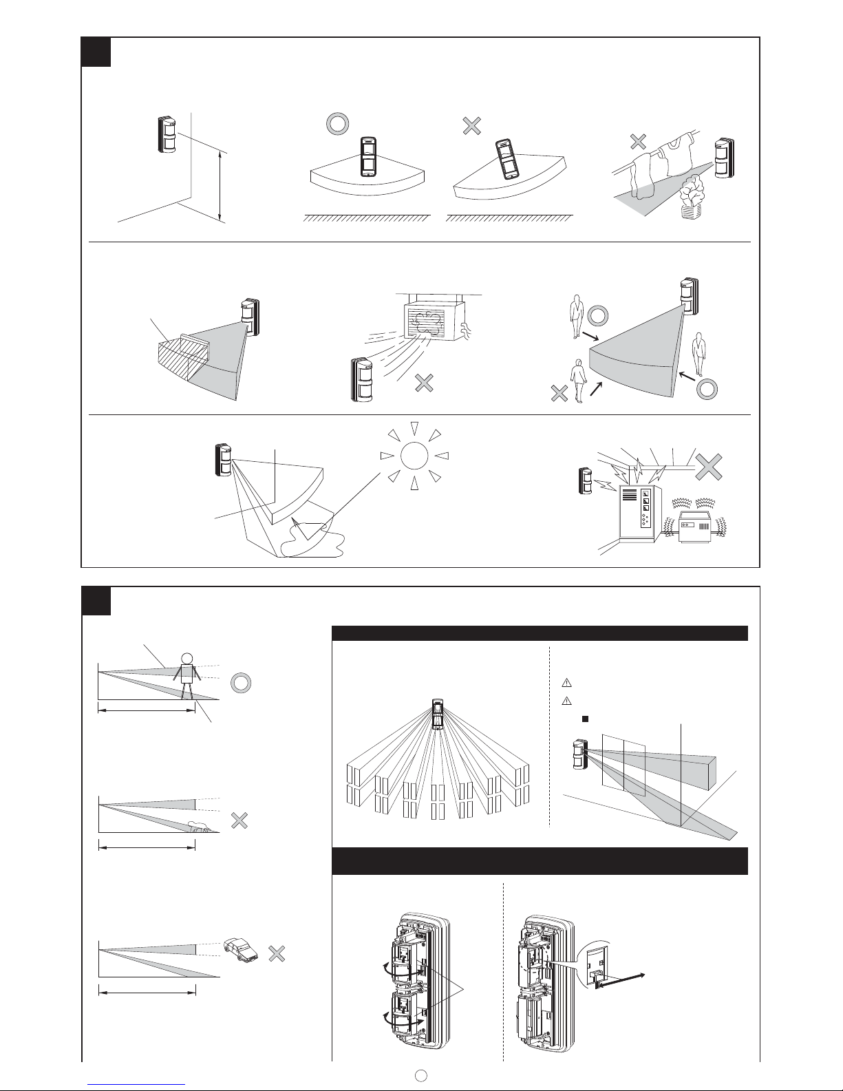
A. Both zones detect
Ambas zonas detectadas
B. Horizontal zone doesn’t detect.
No es posible detectar la zona horizontal.
C. Downward zone doesn’t detect.
No es posible detectar la zona baja.
PATTERNS OF COVERAGE MODELOS DE COBERTURA
AREA ADJUSTMENT [Horizontal adjustment]
AJUSTE DE ÁREA [Ajuste horizontal]
[Wide angle detection]
[Detección de ángulo ancho]
[Wall detection]
[Detección de pared]
Fine adjustment [Wall detection]
Ajuste de precisión [Detección de pared]
±90°
15° pitch
±90°
Giro 15°
±90°
15° pitch
±90°
Giro 15°
Sensor
• Away from the wall.
• Alejado de la pared.
s4OWARDSTHEWALL
s(ACIALAPARED
ALARM
ALARMA
NO ALARM
SIN ALARMA
NO ALARM
SIN ALARMA
2
PRECAUTIONS PRECAUCIONES
2.6'~4.0'
(0.8~1.2m)
Non detection area
Área sin detección
*
Keep installation height 2.6' to 4.0' (0.8 to 1.2m)
*
Mantener la altura de instalación de 2,6' a 4,0'
(0,8 a 1,2 m)
!VOIDEXHAUSTVENT
%VITEVENTILACIØNDEESCAPE
!VOIDSTRONGLIGHT
%VITEILUMINACIØNINTENSA
!VOIDELECTRICALNOISE
%VITERUIDOELÏCTRICO
#ROSSTHEDETECTIONZONE
#RUCELAZONADEDETECCIØN
0ERPENDICULARINSTALLATION
)NSTALACIØNPERPENDICULAR
2EMOVEALLOBSTRUCTIONS
2ETIRETODASLASOBSTRUCCIONES
2EMOVEALLOBSTACLES
2ETIRETODOSLOSOBSTÈCULOS
When using wall detection,
ensure that the count setting is set to 1.
Al utilizar la detección de pared,
asegúrese de que el ajuste del contador está establecido en 1.
o 6 ADJUSTMENT AJUSTE
Page 3
4
DETECTION DISTANCE ADJUSTMENT
AJUSTE DE LA DISTANCIA DE DETECCIÓN
Area of big temperature difference. (ex. cold
winter)
Área de gran diferencia de temperatura. (ej.,
invierno frío)
Area of little temperature difference. (ex. hot
summer)
Área con poca diferencia de temperatura. (ej.,
verano caluroso)
No detection
Sin detección
Detection
Detección
Detection
Detección
Detect human body
Detecta cuerpo humano
Detect vehicles
Detecta vehículos
Short distance
detection
Detección de corta
distancia
Index
Índice
Adjustment lever
Palanca de ajuste
Long distance
detection
Detección de larga
distancia
Detection range
Rango de detección
Detection range
Rango de detección
Horizontal zone
Zona horizontal
Horizontal zone
Zona horizontal
No detection
Sin detección
Downward zone
Zona baja
Downward zone
Zona baja
IMPORTANT NOTES AVISOS IMPORTANTES
40'(12m)
3
5
AREA MASKING SHEET
LÁMINA DE ENMASCARAMIENTO DE ÁREA
Area Masking sheet
Lámina de enmascaramiento de área
Area number Número de área
Cut the necessary
area number
Corte el número de
área necesario
*Zone á cannot be masked by area masking sheet.
*La zona á no puede enmascararse mediante la lámina de enmascaramiento de área.
Cut off
Cortar
Lens holder
Soporte de la lente
Print side
Lado de impresión
ADJUSTABLE: 90° AJUSTABLE: 90°
VARIABLE: 180° VARIABLE: 180°
ADJUSTABLE: 90°
AJUSTABLE: 90°
VARIABLE: 180°
VARIABLE: 180°
15°
Variable
Pitch
Giro
variable
15°
Variable
Pitch
Giro variable
[TOP VIEW]
[
VISTA SUPERIOR
]
Horizontal Detection
Detección horizontal
[TOP VIEW]
[
VISTA SUPERIOR
]
Horizontal Detection
Detección horizontal
TX-114TR/114SR
TX-114FR
90°
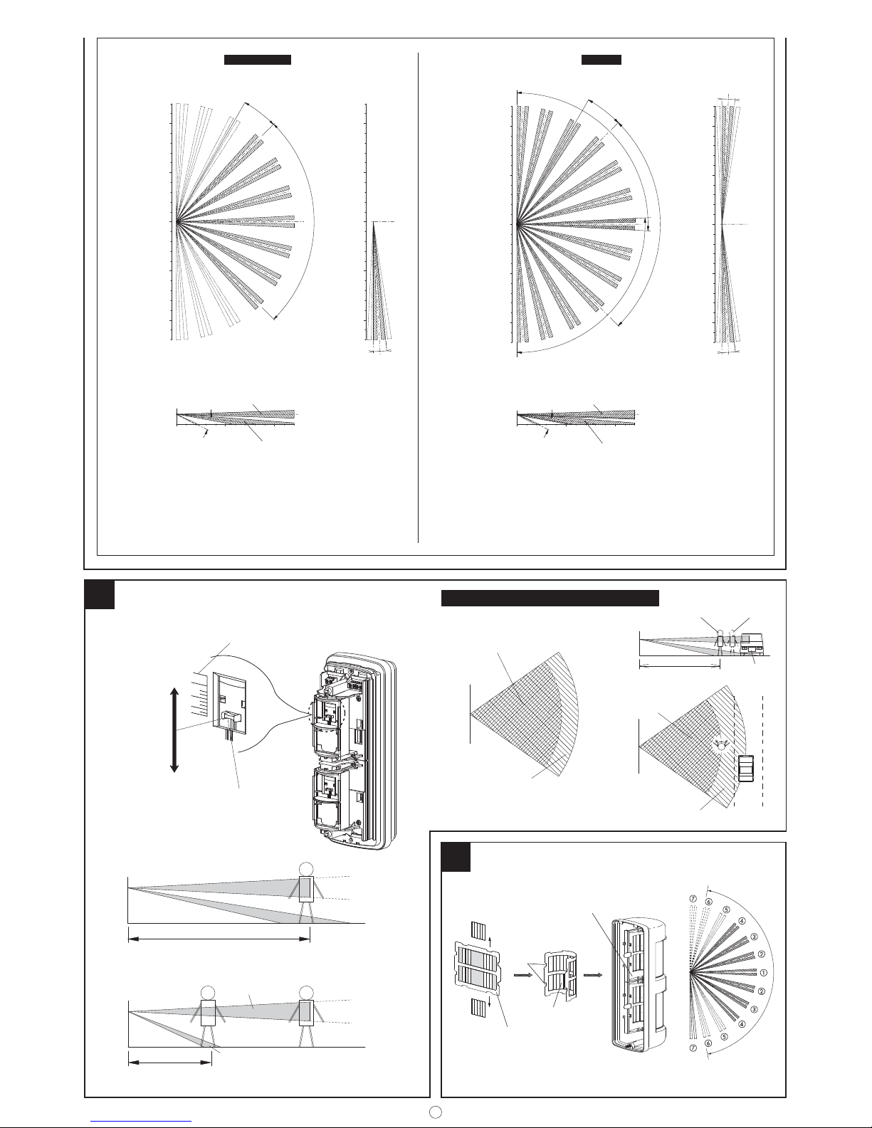
Detection distance is set by adjusting the angle of downward zone.
Adjustable range 6.6' (2m) to 40' (12m). [10 ranges]
La distancia de detección se establece mediante el ajuste del ángulo de la zona baja.
Rango ajustable de 6.6' (2 m) a 40' (12 m). [10 rangos]
Detection distance is set by adjusting the angle of downward zone.
Adjustable range 6.6' (2m) to 40' (12m). [10 ranges]
La distancia de detección se establece mediante el ajuste del ángulo de la zona baja.
Rango ajustable de 6.6' (2 m) a 40' (12 m). [10 rangos]
3°
3°
LOWER SENSOR COVERAGE
COBERTURA DEL SENSOR INFERIOR
UPPER SENSOR
COVERAGE
COBERTURA DEL
SENSOR SUPERIOR
DETECTION
MODE: OR
MODO DE
DETECCIÓN: OR
LOWER SENSOR COVERAGE
COBERTURA DEL SENSOR INFERIOR
UPPER SENSOR COVERAGE
COBERTURA DEL SENSOR SUPERIOR
Fine Adjustment
Ajuste de precisión
× 2
UPPER SENSOR
SENSOR SUPERIOR
LOWER SENSOR
SENSOR INFERIOR
3°
3°
3°
3°
Fine Adjustment
Ajuste de precisión
Masking unnecessary
zones.
Enmascarando zonas
innecesarias.
[TOP VIEW]
[VISTA SUPERIOR]
Wall Detection
Detección de pared
Fine Adjustment
Ajuste de precisión
Masking unnecessary
zones.
Enmascarando zonas
innecesarias.
[TOP VIEW]
[VISTA SUPERIOR]
Wall Detection
Detección de pared
[SIDE VIEW]
[
VISTA LATERAL
]
[SIDE VIEW]
[
VISTA LATERAL
]
DETECTION MODE: OR
MODO DE DETECCIÓN: OR
0
40'
(12m)
33'
(10m)
16.5'
(5m)
(5m)
16.5'
(12m)
40'
(10m)
33'
0
40'
(12m)
33'
(10m)
16.5'
(5m)
(5m)
16.5'
(12m)
40'
(10m)
33'
0
40'
(12m)
33'
(10m)
16.5'
(5m)
(5m)
16.5'
(12m)
40'
(10m)
33'
0
40'
(12m)
33'
(10m)
16.5'
(5m)
(5m)
16.5'
(12m)
40'
(10m)
33'
0
16.5'
(5m)
33'
40'
(1m)
3.3'
(10m)
(12m)
Variable range
Rango variable
Horizontal Zone
Zona horizontal
Downward Zone
Zona baja
0
3.3'
(1m)
40'
33'
(5m)
16.5'
(10m)
(12m)
Variable range
Rango variable
Horizontal Zone
Zona horizontal
Downward Zone
Zona baja
Page 4
4
7
WIRING CABLEADO
Terminal Configuration Configuración del terminal
TX-114TR/114FR
TX-114SR
£Wiring insertion
£
Inserción del cableado
Wiring hole
Orificio del cableado
Battery
Batería
Transmitter
Transmisor
Adhesive sheet
Lámina adhesiva
Power supply needs same or higher voltage than that for transmitter.
Alkaline or Lithium BATTERY ONLY!
El suministro de alimentación necesita poseer el mismo voltaje o superior que el del transmisor.
¡ÚNICAMENTE BATERÍAS alcalinas o de litio!
WARNING ADVERTENCIA
Adhesive sheet
Lámina adhesiva
Bottom space
Espacio inferior
Red
Rojo
Black
Negro
[COMMON BATTERY] [BATERÍA COMÚN]
Common for TX-114TR/FR and Transmitter
Común para TX-114TR/FR y transmisor
[SEPARATE BATTERIES]
[BATERÍAS INDEPENDIENTES]
Each for TX-114TR/FR and Transmitter
Ambas para TX-114TR/FR y transmisor
B
C
TX-114TR/FR
Transmitter
Transmisor
Power
Alimentación
Alarm input
Entrada de
alarma
Alarm
Alarma
Power
Alimentación
Battery
Batería
Battery
Batería
6
ADJUSTMENT AJUSTE
[Factory set]
[
Ajuste predeterminado
]
OFF
ON
10sec. 10 seg. 120sec. 120 seg. 300sec. 300 seg. 900sec. 900 seg.
3 4
OFF
ON
3 4
OFF
ON
3 4
OFF
ON
3 4
556
6
ON
ON
OFF
OFF
3
1
Whole Unit
Toda la
unidad
Back Tamper Killer
Back Tamper killer
Insert Back Tamper Killer in it.
Introduzca Back Tamper Killer en su interior.
Pull up the head.
Levante el cabezal.
Body Unit
Unidad del
cuerpo
Body Unit
Unidad del
cuerpo
Cover
Tapa
Mounting Base
Base de montaje
Mounted Wall or Pole
Instalado en la
pared o barra
[
Factory set
]
[
Ajuste predeterminado
]
Less sensitive; prevents false alarms
caused by temperature fluctuation.
Menos sensitivo; evita las falsas alarmas
causadas por la fluctuación de la
temperatura.
£Output prohibition
timer settings
£
Ajustes de temporizador
de prohibición de salida
£
Pulse count selectable
£
Contador de impulsos
seleccionable
[Back Tamper] [Tamper trasero][Front Tamper] [Tamper frontal]
1
2
A
C
B
*TX-114FR has two sets of above switches
for upper and lower sensor.
*TX-114FR tiene dos juegos de los
anteriores interruptores para el sensor
superior e inferior.
£Warm up period
£
Test mode function
£
Detection signal
£
Trouble alarm
£
Front Tamper signal (Cover removal)
£
Back Tamper signal (Whole unit removal)
£
Período de precalentamiento
£
Función de modo de prueba
£Señal de detección
£
Alarma de problema
£
Señal anti-sabotaje frontal (extracción de tapa)
£
Señal anti-sabotaje trasera (extracción de la totalidad de la unidad)
For details, refer to ADJUSTMENT
on page 6.
Para más detalles, consulte AJUSTE
en la página 8.
TX-114TR/114FR Only Únicamente TX-114TR/114FR
6
6
Set for sensitive detection of even small movements by people,
however this may be more susceptible to false alarms.
For wall detection, use this setting.
Ajustado para una detección sensitiva de incluso el más
mínimo movimiento humano, sin embargo podría ser más
susceptible a falsas alarmas.
Para la detección de pared, use este ajuste.
Battery Lead (red)
Cable Batería (rojo)
Battery Lead (black)
Cable Batería (negro)
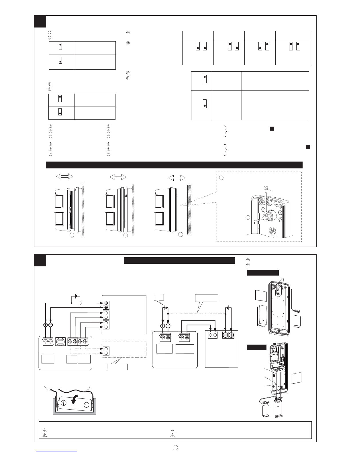
Should you wish to use the transmitters battery to also power the
TX-114 use the supplied 'Battery Leads'. Insert the spade between the
battery terminal and battery holder.
DO NOT modify/strip the cable at the battery end, as this may cause a
short circuit across the battery terminal.
Si desea utilizar la batería del transmisor para alimentar también al
sensor TX-114 utilize los cables de batería suministrado. Inserte la para
entre los bornes correspondientes del soporte y de la batería.
No modificar / pelar el cable en el extremo de la batería, ya que ello
puede causar un corto circuito a través del terminal de la batería.
Transmitter Transmisor
Red Rojo
Black Negro
Blue Azul
Green Verde
Tamper input
Entrada anti-sabotaje
Alarm input
Entrada de alarma
Alarm input
Entrada de alarma
TX-114TR/ FR
Power Alimentación
*
Transmitter Transmisor
A
Alarm
Alarma
Power
Alimentación
Tamper
Battery Batería
1
N.O.
N.O.
N.O.
N.C.
[Factory set]
[Ajuste predeterminado]
N.C.
N.C.
[Factory set]
[Ajuste predeterminado]
N.C.
N.O.
ON
OFF
1
2
ON
OFF
2
£Alarm output selectable
£
Salida de alarma seleccionable
£Tamper output selectable
£
Salida anti-sabotaje seleccionable
Page 5
5
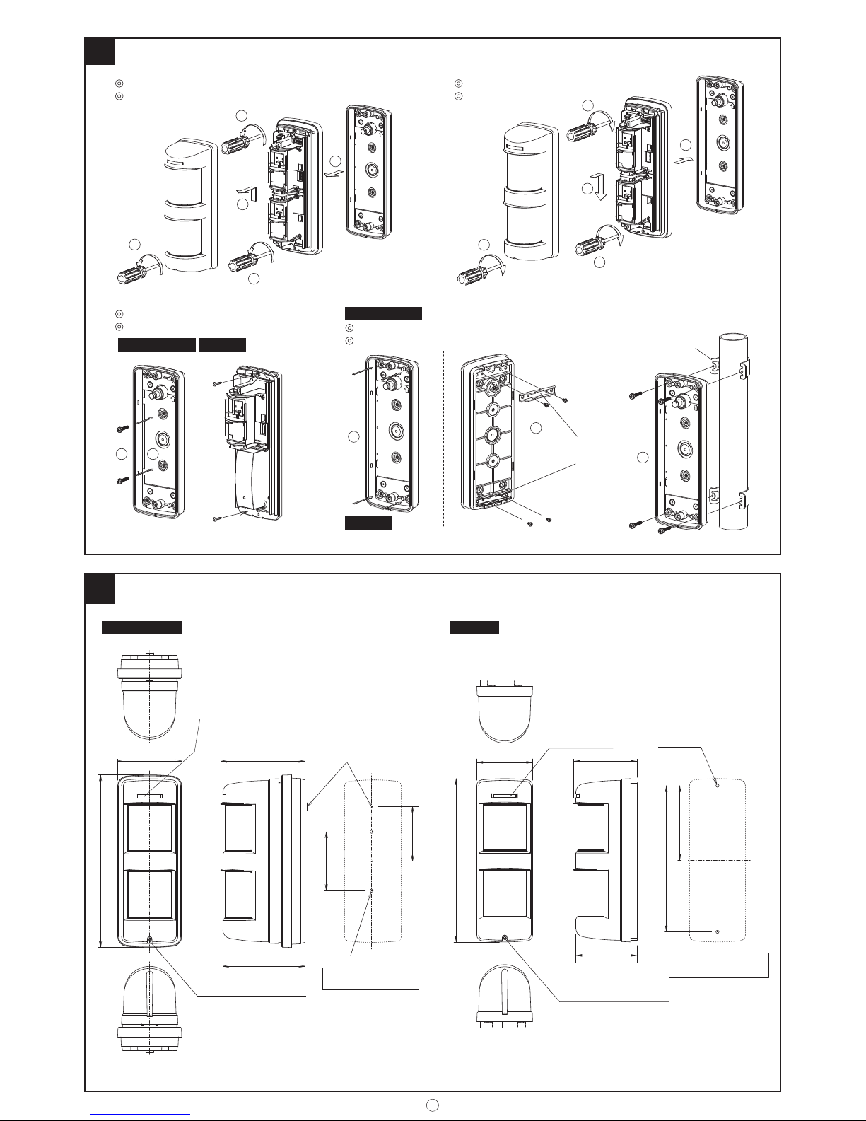
£Pole Mounting
£
Montaje en barra
TX-114TR/114FR
£Assembling
£
Ensamblaje
£
Before the installation
£
Antes de la instalación
£
Wall Mounting
£
Montaje en pared
8
INSTALLATION
INSTALACIÓN
3
1
2
3
4
1
2
3
2
1
U bracket
Soporte U
Pole mounting brackets
Soportes de montaje
para barra
4
3
2
2
1
9
EXTERNAL DIMENTIONS DIMENSIONES EXTERNAS
Cover locking screw
Tornillo de bloqueo de la tapa
Operation LED
LED operacional
(ø4.5mm)
2-ø0.18"
4.70"
4.59"
3.04"
(119.5mm)
(77.25mm)
3.29"
(83.5mm)
(116.5mm)
3.58"
9.65"
Back tamper
Anti-sabotaje trasero
(91mm)
(245mm)
MOUNT HOLE
ORIFICIO DE MONTAJE
TX-114TR/114FR
TX-114SR
TX-114TR/114FR
9.21" (234mm)
3.15"
(80mm)
4.21" (107mm)
8.25" (209.5mm)
2-ø0.18"
(ø4.5mm)
Cover locking screw
Tornillo de bloqueo de la tapa
3.58"
(91mm)
Operation LED
LED operacional
MOUNT HOLE
ORIFICIO DE MONTAJE
3.46"
(88mm)
TX-114SR
Use the pole attachment "BP-32"
(sold separately)
Utilice la fijación a poste "BP-32"
(se vende por separado)
Use the pole attachment "BP-22". (sold separately)
Utilice el acoplamiento de poste "BP-22". (se vende por separado)
TX-114SR
Page 6
6
Instruction Manual TX-114TR/114FR/114SR
We appreciate your purchase of a TAK EX passive
infrared sensor. This sensor will provide long and
dependable service when properly installed. Please
read this Instruction Manual carefully for correct
and effective use.
Please Note:
This sensor is designed to detect intrusion and to
initiate an alarm; it is not a burglary-preventing
device. TAKEX is not responsible for damage,
injury or losses caused by accident, theft, Acts
of God (including inductive surge by lightning),
abuse, misuse, abnormal usage, faulty installation or
improper maintenance.
PRODUCT DESCRIPTION
TX-114TR/TX-114FR /TX-114SR is a passive infrared
sensor with low current consumption, which is
designed to be equipped with a wireless transmitter
in it.
Please confi rm that this unit matches with a
transmitter to be used.
Some transmitters may not perceive the outputs
of this unit.
1) This sensor is equipped with an "AND" detection
and pulse count system which improve the reliability of the sensor when it is used in severe outside
environment.
2) The A ND detection system will issue an alarm
signal only when detecion occurs in both horizontal and downward zones simultaneously.
3) The sensor is equ ipped wit h back and front tamp er
switches.
The front tamper switch issues a signal when the
cover is detached f rom the unit.
The back tamper switch issues a signal when the
whole unit is detached from a mounted wall or
pole.
2 PRECAUTIONS
• Operation LED blinks for about 1min after turning
on power.
During this warm up period, the sensor does not
detect.
• Do not pour water on this unit with a hose as it is
designed to be rainproof, not waterproof.
• When detection mode is set at AND mode, this
sensor outputs an alarm signal only when both
upper and lower sensor detect objects.
In other words, it won't make detection in the
area which is not covered by both upper and lower
sensor.
[Only applicable to TX-114FR]
•Powersupply is Aikaline or Lithium Batter y only.
• Powersupply needs same or higher voltage than
that for transmitter.
[Detection area]
(The area covered by both
upper and lower sensor)
Lower sensor coverage
(No detection)
Upper sensor coverage
(No detection)
3 DETECTION AREA
The detect ion zone of this unit consists of a horizont al
zone and downward zone.
Alarm signal is issued only when both detection
zones detect objects.
Detection distance can be set by adjusting the angle
of downward zone.
TX-114TR/114SR is equipped with 1set of sensors on
the upper side.
TX-114FR is equipped with 2sets of sensors on the
upper and lower side, making it possible to select
AND mode or OR mode.
A. Alarm signal is issued only when both horizontal
and downward zone detect objects.
B. It does not detect small animals which are not
likely to reach the height of horizontal zone.
C. It does not detect vehicles moving in the area
outside the range of the downward zone.
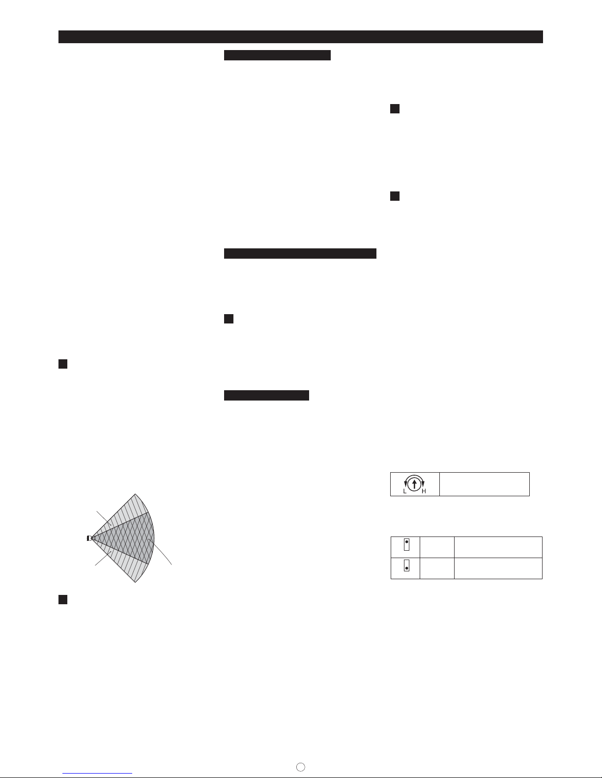
PATTERN OF COVERAGE
[Wide angle detection]
(1) Point the sensor to the center of the area to be
detected. By t urning the sensor up to ±45°, it can
detect all zones in front of it.
When the unit is turned more than ±45°, detection
zone will be eliminated one by one from the end.
(2) It consists of seven detection zones.
(Wide angle: 90°)
(3) Ustilize attached area masking sheet when elimi-
nating detection zones.
[Wall detection]
(1) Attach area masking sheet to the lens holder
(inside the cover) without cutting it out.
(Refer to Area mask ing on how to attach the sheet
to the lens holder.)
(2) R otate the s ensor by 90 ° and face i t to the dir ection
to be detected.
(3) Horizontal fi ne adjustment
Fine adjustment can be made within the range of
±3°, in case there is some obstacles on the wall.
( Det ect io n zo ne sh if ts abo ut 2 ' (0 .6m ) at 4 0' (12 m)
range.)
Slide the lever to the left or right.
AREA ADJUSTMENT [Horizontal adjustment]
• Make sure that the lever be set at 0° for horizontal
detection.
· When shifting detection zone away from the wall,
slide the lever towards the wall.
· W hen shif ting det ection zone t owards the w all, slid e
the lever away from the wall.
4
DETECTION DISTANCE ADJUSTMENT
Detection distance can be adjusted within a range
from 6.6' (2m) to 40' (12m) by turning the angle of
downward zone vertically.
Refer to the index and slide the adjustment lever up
or down.
Slide it up and the detection distance becomes
shorter, sliding it down, detection distance becomes
longer.
IMPORTANT NOTES
The fol lowing fa ctors may ha ve an effec t on the actua l
detection range or sensitivity.
The g reater t he dist ance cover ed, the mor e promin ent
this effect becomes.
•Ambient temperature vs object temperature.
Actual detection range may decrease when the
object being detected of similar temperature to the
ambient target area.
•Direction of object path.
PIR detection works best when movement crosses
the sensitive zones. Sensitivity deteriorates when
movement is directly towards the detector within
single zones.
•Mounting height.
The cl oser the mounting he ight is to the gr ound, the
shorter the achievable detection range.
•Mounting orientation.
Detector should be installed on a true vertical to
ensure proper detection range.
•Slope in detection area
When the ground slopes downward (upward) from
the sensor, the detection range becomes longer
(shorter).
The following settings should be appropriately
adjusted by WALK T EST in order to obtain expected
performance of the detector according to the various
environment al factors of the installation site.
•Detection range adjustment.
(Adjustment lever with 10 steps)
The distance index is not defi nitive and is onl y to be
used as a guide.
•Area setting.
Set the area so that the object crosses the area in
maximum cases.
•Sensitivity setting (by PIR SENS pot).
Note that the actual detection range may lessen
by up to 20 % when the ambient temperature is
enough high so that there is a little temperature
difference between the object to be detected and
the background.
(See below fi gure)
If this situation is likely then it is recommended to
increase the detection range to compensate.
• When there is a path or road at the front of
detection zone, vehicles with comparatively higher
temperature than human body may be detected at
a longer distance. Readjust the area setting and
range adjustment when there is such undesirable
detections.
5 AREA MASKING SHEET
(1) Cut the necessar y area number on the area mask-
ing sheet.
See the area masking picture for your reference
and cut out the same place on both horizontal and
downward zones.
(2) Attach the area masking sheet to the lens holder
located inside cover.
(3) Att ach cover and check detection zone.
*Zone á cannot be masked by area masking sheet.
6 ADJUSTMENT
Warm up period
|
|
Oper ation L ED bli nks for abo ut 1 min a fter c onnec ting
a battery to the unit .
The unit doesn't operate for this time as it is the
sensor stabilizing period.
After warming up, the unit will be in the test mode
automatically.
Test mode function
|
|
The unit is equipped with the test mode function
which makes easy operation check possible.
Af ter approx .1 min of war m up period, t he unit wil l be
in the test mode automatically as follows.
LED: Lights at detection.
Alarm signal: Output prohibition time is set at 10
sec regardless of the settings of the
timer.
* Test mode will be terminated 5 minutes after the
cover is fi rmly attached.
*LED lights only while test mode.
Detection signal
|
|
The unit issues one shot al arm signal when det ecting
human beings.
Output can be controlled by the signal prohibition
time settings.
LED lights only when the unit is in the test mode.
Output prohibition timer settings
|
|
During a set prohibition time after issuing an alarm,
another signal would not be issued in order to minimize current consumption.
The output prohibition time is selectable among
10sec./120sec./300sec./900sec. by dip switch.
Sensitivity adjustment
|
|
Sensitivity can be adjusted
between 30% (L) and 170% (H).
[Factory set : 100%]
*Adjust the mark to the index.
* TX-114FR has two sets of above volumes for upper
and lower sensor.
Detection mode [Only app l i cable to TX-114FR]
|
|
7
7
ON
OFF
[Factory set]
AND
OR
Alarm signal is issued only when
both upper and lower sensor
detect objects simultaneously.
Ala rm sig nal is i ssued wh en
eithe r upper or lo wer sens or
detect objects.
Trouble alarm
|
|
The unit issues a trouble alarm and triggers the LED
blinking when it suffers functional troubles such as
circuit failure or wire disconnection in case of N.C.
setting.
In this case, detach the cover and check the sensor
referring to the OPERATION CHECK.
Front tamper signal (Cover removal)
|
|
The unit issues a tamper signal when its cover is
detached from the unit.
Once the cover is attached to the sensor again, the
operation will be recovered.
Then t he unit w ill go int o the test mo de and 5 min a fter
which, it will be in an operation mode automatically.
(LED doesn’t light when the tamper signal is
issued.)
Back Tamper signal (Whole unit removal)
|
|
The unit issues a tamper signal when whole unit is
removed f rom a mounted wall or pole.
Page 7
7
When the unit is mounted on unlebel wall,back
ta mper swi tch could be ke pt tu rni nig on . In this cas e,
use B.T.Killer which can disable the function ©.
7 WIRING
Terminal Confi guration
[COMMON BATTERY]
Common for TX-114TR/FR/SR and Transmitter
When connecting this unit to the transmitter
which has no input terminals for tampers, connect
alarm and tamper terminals of this unit in ser ies.
Both alarm and tamper signals can be outputted.
(Select N.C. for contact output.)
SUPPLY VOLTAGE
•3 to 9VDC Alkaline or Lithium Battery (polarity)
•Current Consumption
(Except test-mode period)
25 μA (TX-114TR/114SR)
35 μA (TX-114FR)
• When a connected transmitter doesn’t accept the
output, to shor t curcuit bet ween terminal of this
unit and the negative pole of the bat tery for the
transmitter may solve the problem.
ALARM
•Solid State Switch form N.O./N.C. selectable
•10VDC · 0.01 A Max
[Detection Alarm] OR [Trouble Alarm]
TAMPER
•Solid State Switch form N.O./N.C. selectable
•10VDC · 0.01 A Max
[Front Tamper] OR [Back Tamper]
[SEPARATE BATTERIES]
Each for TX-114TR/FR/SR and Transmitter
Powersupply needs same or higher voltage than
that for transmitter
When a connected transmitter doesn’t accept the
output, to connect the terminal of TX-114TR/
FR/SR and the negative pole of the battery for the
transmitter may solve the problem.
Wiring insertion
|
|
(1) Put t he wire th rough the wi ring holes a nd connect
them to the battery and transmitter and the
terminals.
(2) Fix the transmitter and battery on the back box
with the adhensive sheets.
* When connecting this unit to the transmitter which
has no input terminals for tampers, connect alarm
and tamper terminals of this unit in series.
Both alarm and tamper signals can be outputted.
(Select N.C. for contact output.)
8 INSTALLATION
Before the installation
|
|
Read 2 PRECAUTIONS before the installation.
(1) Loosen the cover locking screw.
(2) Remove the cover.
(3) Loosen the body locking screws.
(TX-114TR/114FR only)
(4) Remove the body unit. (TX-114TR/114FR only)
Wall Mounting
|
|
TX-114TR/114FR
(1) Break 2 knockouts on the mounting base.
(2) Install the base to the wall with 2 tapping screws.
[Installed pitch: 3.29" (83.5mm)]
TX-114SR
(1) Install the base to wall w ith 2 tapping screws.
[Installed pitch:8.25" (209.5mm)]
Pole Mounting
|
|
TX-114TR/114FR
Use the pole attachment "BP-32" (sold separately)
Use a 1.66" to 1.75" (38mm to 45mm) outer diameter
pole
(1) Break 4 knockouts on the mounting base.
(2) Attach 2 pole mounting brackets to the backside
of the base with 4 tapping screws.
(3) Place the U brackets on the back of the pole.
Attach the mouting base to the U bracket w ith
pole mounting screws.
(4) Refer to
7 WIRI
NG and connect wires to the
terminals.
TX-114SR
Use the pole attachment "BP-22" (sold separately)
A
B
C
Assembling
|
|
(1) Attatch the Body unit to the Mounting Base.
(TX-114TR/114FR only)
(2) Fasten the Body locking screws.
(TX-114TR/114FR only)
* Carry out OPERATION CHECK with the cover
detatched.
(3) Replace the cover.
(4) Fasten the Cover locking screw.
OPERATION CHECK
• Refer to the 3 DETECTION AREA, and set the
horizontal angle and detection distance.
• Make functional settings in accordance with the
purpose of use of this unit.
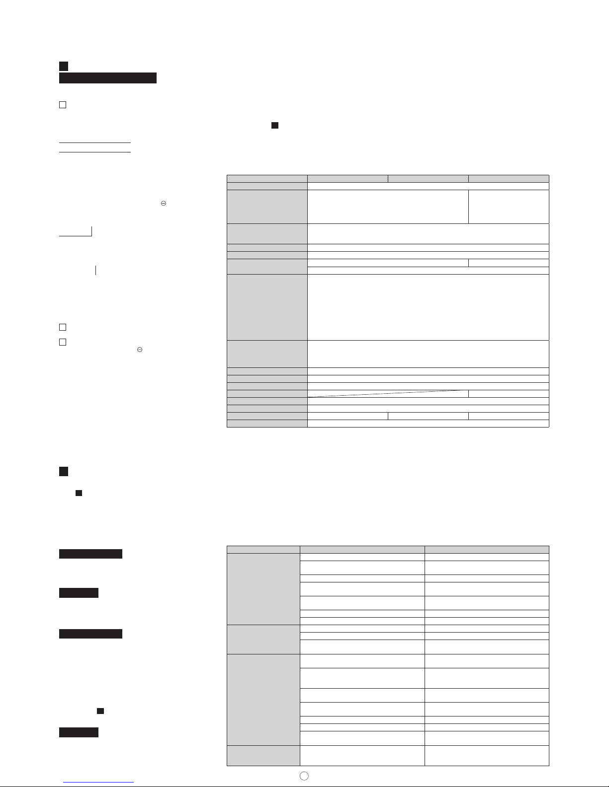
SPECIFICATIONS
Model TX-114SR TX-114TR TX-114FR
Detection system Passive infrared
Coverage
When horizontal detection
Angle: 90°
Detection distance: 40' (12m)
Horizontal zone: 7zones
Downward zone: 7zones
2sets of
TX-114SR / TX-114TR
sensors
Coverage adjustment
Horizontal: 90 degrees
Detection distance: 6.6' to 40' (2m to 12m)
(Adjustable by changing the vertical angle of downward curtain)
Supply voltage 3V to 9VDC Alkaline or Lithium Battery
Operation volta ge 2.3V to 10VDC (Battery)
Current consumption
25 μA for detec tion 35 μA for dete ction
5mA/3V (Test mode)
Operation
Solid St ate Switc h N.C./N.O. selecta ble
10VDC · 0.01A Max
zAlarm output
|
|One shot output when detect ing human beings (approx. 2sec)
zTamp er o utp ut
|
|Real time output
•when the cover is detatched from the unit
•when the unit is detatched from the installed wall or pole. (TX-114TR/TX-114FR Only)
zTrouble output
|
|Real time output when the unit suffers fun ctional trouble. (from terminal of Alarm)
Operation LED
Red LED
•Blinking for approx. 1min at warming-up
•Lighting for 1sec at detection during walk-test (LED lights only in a test-mode)
•Blinking when trouble alarm is issued (Lights once every 5 sec)
Sensitivity adjustment
Approx. 30% to 170% (By volume)
Pulse count 1/3 selectable with a dip switch
Alarm prohibition time 10sec/120sec/300sec/900sec selectable with dip switches
Detection mode AND/OR selectable
Ambient temperature -4°F to +122°F (-20°C to +50°C)
Mounting position Indoor/Outdoor [Wall or Pole]
Weight 14oz (400g) 19.6oz (560g) 21.7oz (620g)
Appearance Body: AES resin Lens: PE resin
TROUBLESHOOTING
Trouble Check Corrective Action
Completely inactive
•Batter y is unconnected or low batter y. •Connect battery or replace battery.
• Cover is shielded by substances (including
glass).
•Remove the substances.
•Improper area adjustment. •Readjust the protection area setting.
•
Not yet about 1minute after a batter y is connected
to the unit. (Operation LED is flickering.)
•Allow for warming up time (a bout 1min.)
• The voltage of powersupply is lower than that
for transmitter.
•Use same or higher voltage than transmitter.
•Incorrect polarity of powersupply •Change the polarity.
•Improper setting of output form •Select the correc t setting.
Sometimes inactive
•Improper area adjustment. •Readjust the protection area setting.
•Cover face is soiled wi th dust or water drop. •Clean the cover with soft cloth.
• Detection occurs within the signal prohibition
time set by a d ip switch.
• If the sensor sen ds a signal after the
prohibition time is over, its function is normal.
Activated when no person
has passed
• Something moving in protected area or too
rapid temperature variations.
•Remove the cause.
•
Large electric al noise source such as power
machine nearby or it s wiring close to that of
sensor.
•Relocate device.
• Intense refl ection of sun light or head light
shining on the sensor.
• Relocate device. Readjust the protection area
setting.
• Reflective lights such as sun light or head
light af fect the downward zone.
•Remove refl ective objects.
•Readjust the protection area setting.
•Improper installation of the sensor. •Install the sensor ver tically.
•
Detection distance of the downward zone is too long.
•Readjust detection distance.
• Cars or motor bikes locate d at the front of
detection area may activate the sensor.
•
Readjust the area setting and range adjustment
so that there is no such undesirable detections.
LED lights on once every
5 min though the unit is
not in a test m ode
•The unit suffers functional trouble. (Trouble
signal is issued.)
•Check the function of the sensor.
Solve possible problems according to the following table. If normal operations cannot be
re stored by this means, contact either the dea ler from whom you bought the unit or TAKEX.
• Connect the battery to the unit after which approx.
1 min warm up period st arts.
• Attach the cover to the unit and fi x it by tightening
the cover locking screw.
(After the warm up time is over and the cover is
att ached to the s ensor, the unit w ill be in a te st mode
for about 5 min.)
• After the warm up time is over, operate a walk test
and che ck the locat ion and size o f the detect ion area
through the LED.
• If necessary, readjust the angle and distance of
the detection area as well as sensitivity and pulse
count.
* Make sure that there is no undesirable detection of
traffi c including vehicles if there is a path or road at
the front of detection zone.
Limited Warranty:
TAK EX products are warranted to be free from
defects in material and workmanship for 12 months
from original date of shipment. Our warranty does
not cover damage or failure caused by Acts of God
(including inductive surge by lightning), abuse,
misuse, abnormal usage, faulty installation, improper
maintenance or any repairs other than those
provided by TAKEX. All implied warranties with
respect to TA KE X, including implied warranties for
merchantability and implied warranties for fi tness,
are limited in duration to 12 months from original date
of shipment. During the Warranty Period, TAKEX
wi ll rep air or re pl ace , at i ts s ole o pt ion, f ree o f ch arg e,
any defective parts returned prepaid. Please provide
the model number of the products, original date of
shipment and nature of diffi culty being experienced.
There will be charges rendered for product repairs
made after our Warranty period has expired.
Page 8
8
Manual de instrucciones TX-114TR/114FR/114SR
Le agradecemos que haya adquirido un sensor de
infrarrojos pasivo TAKEX. Instalar correctamente
este sensor proporcionará una larga vida útil de alta
fi abilidad. Por favor, lea detenidamente este manual
de instrucciones para un uso correcto y efectivo.
Atención:
Este sensor est á diseñado para detectar intrusiones e
inic iar una al arma; no e s un disposi tivo de preven ción
de robo. TA KEX no se hace responsable por daños,
lesiones o pérdidas ocasionados por accidentes,
robos, desastres naturales (incluyendo las cargas
inductivas causadas por relámpagos), abuso, mal uso,
uso ano rmal, i nstalac ión defect uosa o mant enimient o
inadecuado.
DESCRIPCIÓN DEL PRODUCTO
TX-114TR/TX-114FR/TX-114SR es un sensor de
infrarrojos pasivo de bajo consumo de corriente,
diseñado para ser equipado con un transmisor
inalámbrico en su parte trasera.
Confi rme q ue esta unidad coin c i da con el tra ns-
misor a utilizar.
Algunos transmisores podrían no percibir las
emisiones de esta unidad.
1) Este sensor está equipado con una detección
"AND" y un sistema contador de impulsos, el cual
mejora la fi abilidad del sensor al utilizarse en un
entorno exterior severo.
2) El sistema de detección AND emitirá una señal de
alarma únicamente al producirse la detección en
las zonas horizontal y baja simultáneamente.
3) El sensor está equipado con interruptores antisabotaje trasero y delantero.
El interruptor anti-sabotaje delantero emite una
señal al extraer la tapa de la unidad.
El interruptor anti-sabotaje trasero emite una
señal cua ndo to da la u nidad es e xtraíd a de la p ared
o barra de instalación.
2 PRECAUCION ES
• El LED operacional parpadea durante aproximada-
mente 1 minuto al encender la alimentación.
Durante este período de precalentamiento, el
sensor no detecta.
• No derrame agua sobre esta unidad con una man-
guera ya que está diseñada para soportar la lluvia
no está hecha a prueba de agua.
• Cuando el modo de detección está ajustado al modo
AND, este sensor emite una señal de alarma únicamente si tanto el sensor inferior como el superior
detectan objetos.
En otras palabras, no realizará la detección en
el área no cubierta por los sensores superior e
inferior.
[Únicamente aplicable a TX-114FR]
• El suministro de alimentación es únicamente una
batería alcalina o de litio.
• El suministro de alimentación necesita poseer el
mismo voltaje o superior que el del transmisor.
[Zona de detección]
(El área cubierta por el
sensor superior e inferior)
Cobertura del sensor
inferior (sin detección)
Cobertura del sensor
superior (sin detección)
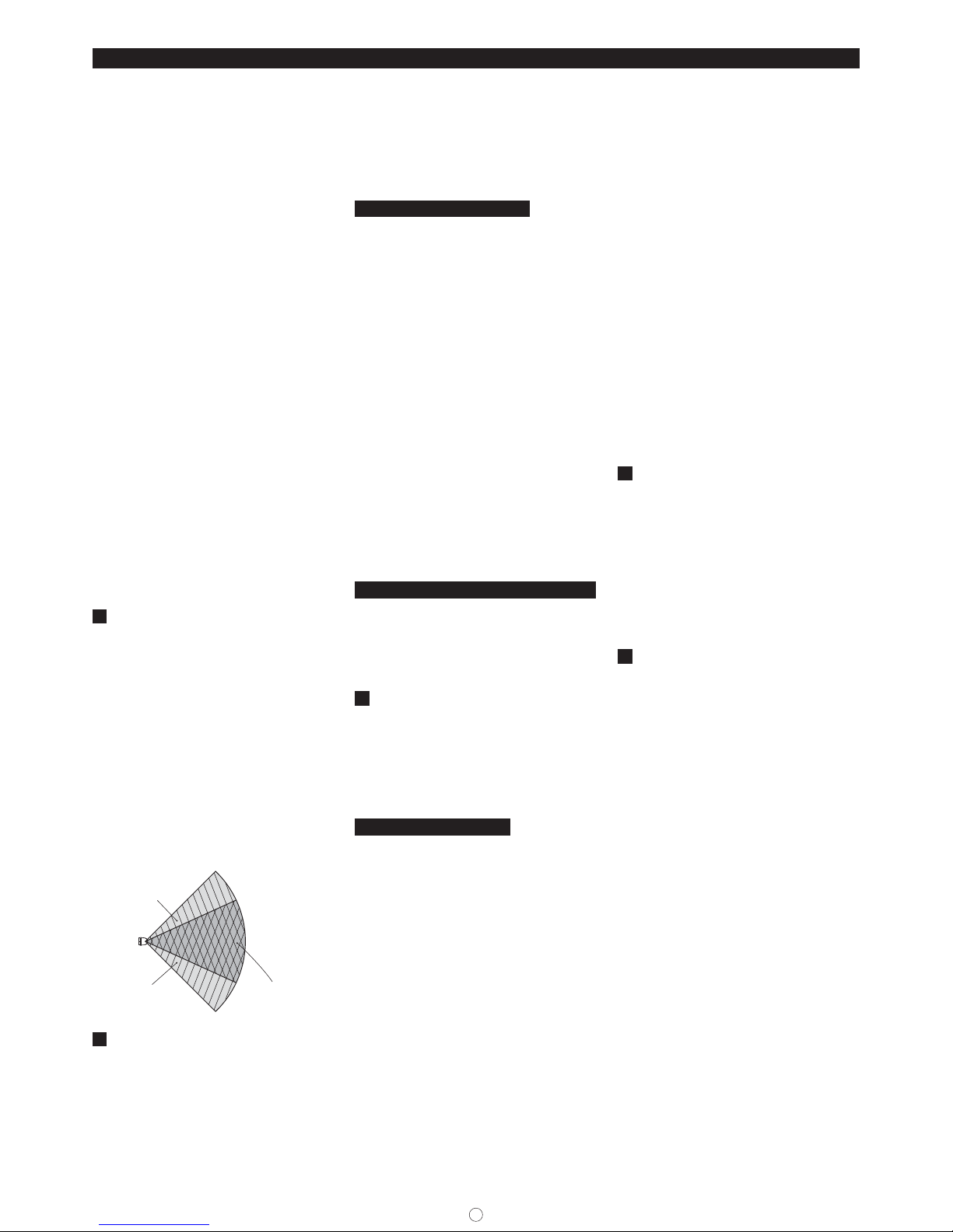
3 ZONA DE DETECCIÓN
La zona de detección de esta unidad consiste de una
zona horizontal y una zona baja.
La señal de alarma es emitida únicamente cuando
ambas zonas de detección detectan objetos.
La distancia de detección puede ser confi gurada por
el ajuste del ángulo de la zona baja.
TX -114T R/114SR está equip ado con 1 juego de s ensores en el lado superior.
TX-114FR está equipado con 2 juegos de sensores
en el lado superior y en el inferior, posibilitando
seleccionar el modo AND o el modo OR.
A. La señal de alarma es emitida únicamente
cuando ambas zonas de detección, horizontal y
baja, detectan objetos.
B. No detecta pequeños animales que probablemen-
te no alcanzarán la altura de la zona horizontal.
C. No detecta vehículos moviéndose en el área
exterior del rango de la zona baja.
MODELO DE COBERTURA
[Detección de ángulo ancho]
(1) Apunte el sensor al centro del área a detectar.
Gira ndo el sensor ha sta un máximo de ± 45°, pod rá
detectar todas las zonas delante del mismo.
Al girar la unidad más de ±45°, las zonas de
detección serán eliminadas una a una desde el
extremo.
(2) Consiste de siete zonas de detección.
(Ancho de ángulo: 90°)
(3) Utilice lá mina de enmascara miento de área adjun-
ta al eliminar zonas de detección.
[Detección de pared]
(1) Coloque la lámina de enmascaramiento de área en
el soporte de la lente (en el interior de la tapa) sin
cortarla.
(Consulte el enmascaramiento de zona para
averiguar cómo adherir la lámina al soporte de la
lente.)
(2) Gire el sensor 90° y colóquelo delante de la direc-
ción a detectar.
(3) Ajuste de precisión horizontal
El ajuste de precisión puede hacerse dentro de un
rango de ±3°, por si acaso existen obstáculos en
la pared.
(La zona de detección se desplaza aproximadamente 2' (0,6 m) en un rango de 40' (12 m).)
Deslice la palanca hacia la izquierda o derecha.
AJUSTE DE ÁREA [Ajuste horizontal]
• Asegúrese de que la palanca esté ajustada a 0° para
la detección horizontal.
· Al alejar la zona de detección de la pared, deslice la
palanca hacia la pared.
· Al acercar la zona de detección a la pared, deslice la
palanca en dirección contraria a la pared.
4
AJUSTE DE LA DISTANCIA DE DETECCIÓN
La distancia de detección puede ajustarse en un
rango de 6.6' (2 m) a 40' (12 m) girando el ángulo de
la zona baja verticalmente.
Consulte el índice y deslice la palanca de ajuste hacia
arriba o hacia abajo.
Si la desliza hacia arriba la distancia de detección
se acor ta, si la desliza hacia abajo la distancia de
detección aumenta.
AVISOS IMPORTANTES
Los siguientes factores podrían afectar el rango de
detección o la sensibilidad actuales.
Cuanto mayor sea la distancia cubierta, más obvio
será este efecto.
• Temperatura ambiental versus temperatura del
objeto.
El rango de detección actual podría disminuir si el
objeto a detectar posee una temperat ura similar a la
de la zona objetivo.
•Dirección de la ruta del objeto.
La detección PIR funciona mejor cuando el movimient o cruza l as zonas sen sitivas . La sensibi lidad se
deter iora si el movimiento se produce directamente
hacia el detector dentro de zonas individuales.
•Altura de montaje.
Cuanto más cerca se encuentre la altura de montaje del suelo, menor será el rango de detección
obtenible.
•Orientación de montaje.
El detector debe instalarse verticalmente para
asegurar un rango de detección adecuado.
•Pendiente en la zona de detección
Si el suelo se inclina hacia abajo ( hacia arriba) del
sensor, el rango de detección aumenta (disminuye).
Los siguientes ajustes deberán ser debidamente confi gurados mediante la PRUEBA DE
DESPLAZAMIENTO con la fi nalidad de obtener el
rendimiento esperado del detector en conformidad
con los distintos factores ambientales del lugar de
instalación.
•Ajuste del rango de detección.
(Palanca de ajuste con 10 pasos)
El índice de la distancia no es defi nitivo y se utiliza
únicamente a modo de guía.
•Ajuste de área.
Considere la dirección probable de desplazamiento
del objeto para ma ximizar la posibil idad de cruce de
las zonas sensitivas.
• A juste de la sensibilidad (media nte el potenciómetro
del SENSOR PIR).
Tenga en cuenta que el rango de detección actual
podría reducirse en hasta un 20% si la temperatura
ambiental es tan alta que existe muy poca diferencia
entre la temperatura del objeto a detectar y el fondo.
(Consulte la siguiente imagen)
En dicho caso, se recomienda aumentar el rango de
detección para compensar.
• Si hay un camino o carretera delante de la zona
de detección, los vehículos con una temperatura
comparablemente superior a la del cuerpo humano
será n detect ados a mayor d istanc ia. Par a evita r tales
detecciones no deseadas, reajuste la confi guración
del área y el ajuste del rango.
5
LÁMINA DE ENMASCARAMIENTO DE ÁREA
(1) Corte el número de área necesario en la lámina de
enmascaramiento del área.
Consulte la imagen del enmascaramiento del área
a modo de referencia y corte los mismos lugares
en las zonas horizontal y baja.
(2) Coloque la lámina de enmascaramiento de área
en el soporte de la lente ubicado en el interior de
la tapa.
(3) Coloque la tapa y compruebe la zona de
detección.
* La zona á no puede enmascararse mediante la
lámina de enmascaramiento de área.
6 AJUSTE
Período de precalentamiento
|
|
El LED operacional parpadeará durante aproximadamente 1 minuto tras conectar una batería en la
unidad.
La unidad no funcionará durante este período ya que
es el período de estabilización del sensor.
Tras el precalentamiento, la unidad entrará en el
modo de prueba automáticamente.
Función de modo de prueba
|
|
La unidad está equipada con una función de modo
de prueba la cual facilita la comprobación del
funcionamiento.
Transcurrido aprox. 1 minuto del período de precalentamiento, la unidad entrará en el modo de prueba
automáticamente de la siguiente manera.
LED: Se ilumina durante la detección.
Señal de alarma: El tiempo de prohibición de salida
está ajustado a 10 s eg. sin impo rtar
los ajustes del temporizador.
* El modo de prueba fi nalizará 5 minutos después de
instalar fi rmemente la tapa.
* El LED se ilumina únicamente durante el modo de
prueba.
Señal de detección
|
|
Al detectar personas, la alarma emite un disparo de
señal de alarma.
La emisión puede controlarse mediante los ajustes
del tiempo de prohibición de la señal.
El LED se ilumina únicamente cuando la unidad se
encuentra en el modo de prueba.
Ajustes de temporizador de prohibición de salida
|
|
Durante el tiempo de prohibición establecido tras la
emisión de una alarma, no se emitirá ninguna otra
señal para minimizar el consumo de corriente.
El tiempo de prohibición de salida se selecciona
entre 10 seg./120 seg./300 seg./900 seg. mediante el
interruptor DIP.
Page 9
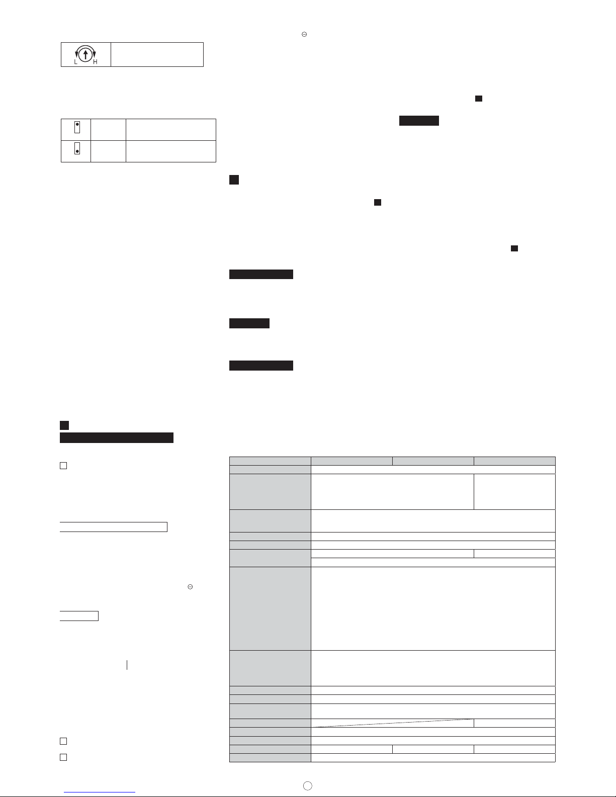
9
Ajuste de sensibilidad
|
|
La sensibilidad puede ajustarse
entre 30% (mín.) y 170% (máx.).
[Ajuste predeterminado: 100%]
*Ajuste la marca al índice.
* T X -114 FR tiene dos juegos de los volúmenes ante-
riores para el sensor superior e inferior.
Modo de detección [Únicamente
|
|
aplicable a TX-114FR]
7
7
ON
OFF
[Ajuste predeterminado]
AND
OR
La señal de alarma es emitida únicamente
cuando los sensores superior e inferior
detectan objetos simultáneamente.
La señal de a larma es emitida
cuando c ualquiera de los se nsores,
superior e in ferior, detectan o bjetos.
Alarma de problema
|
|
La unidad emite una alarma de problema y activa el
parpadeo del LED al sufrir problemas funcionales,
como por ejemplo el fallo de un circuito o la desconexión de un cable.
En dicho caso, extraiga la tapa y compruebe el
sensor consultando la COMPROBACIÓN DE
FUNCIONAMIENTO.
Señal anti-sabotaje frontal (extracción de tapa)
|
|
La unidad emite una señal anti-sabotaje al extraer la
tapa de la unidad.
Una vez la tapa ha vuelto a ser colocada en el sensor,
el funcionamiento se reanuda.
A continuación, la unidad entrará en el modo de
prueba y transcurridos 5 min. entrará automáticamente en un modo operativo.
(El L ED no se ilumina al emitirse la señal antisabotaje.)
Señal anti-sabotaje trasera (extracción
|
|
de la totalidad de la unidad)
La un idad emite u na señal anti- sabotaje s i la totalidad
de la unidad ha sido ext raída de la pared o ba rra en la
que estaba instalada.
Si la unidad se encuentra instalada en una pared no
nivelada, el interruptor anti- sabotaje trasero podría
encenderse continuamente. En dicho caso, utilice
B.T.Killer, el cual podrá desactivar la función ©.
7 CABLEA DO
Confi guración del terminal
[BATERÍA COMÚN]
Común para TX-114TR/FR/SR y transmisor
Al conectar esta unidad al transmisor, el cual no
posee terminales de entrada anti-sabotaje, conecte la alarma y los terminales anti-sabotaje de esta
unidad en serie.
Tanto la señal de alarma como la alarma antisabot aje p ueden emit irs e. (S elec cione N.C. p ara l a
salida de contacto.)
VOLTAJE DEL SUMINISTRO
•Batería de litio o alcalina de 3 a 9 V CC (polaridad)
•Consumo de corriente
(Excepto en el período del modo de prueba)
25μA (TX-114TR/114SR)
35μA (TX-114FR)
• Si uno de los transmisores conectado no acepta la
emisión, cortocircuitar entre el terminal de esta
unidad y el polo negativo de la batería del transmisor podría solucionar el problema.
ALARMA
• Forma de interruptor en estado sólido N.O./N.C.
seleccionable
•10 V CC · 0,01 A máx.
[Alarma de detección] OR [Alarma de problema]
ANTI-SABOTAJE
• Forma de interruptor en estado sólido N.O./N.C.
seleccionable
•10 V CC · 0,01 A máx.
[Anti-sabotaje delantero] OR [Anti-sabota j e
trasero]
[BATERÍAS INDEPENDIENTES]
Ambas para TX-114TR/FR y transmisor
El suministro de alimentación necesita poseer el
mismo voltaje o superior que el del transmisor
Si el transmisor conectado no acepta la emisión,
A
B
C
conectar el terminal de TX-114TR/FR/SR y el
polo negativo de la batería del transmisor podría
solucionar el problema.
Inserción del cableado
|
|
(1) Introduzca el cable a través de los orifi cios de
cableado y conéctelos a la batería y transmisor y
a los terminales.
(2) F ije el t ran sm iso r y la bat erí a en la c aja t ra ser a co n
las láminas adhesivas.
* Al conectar esta unidad al transmisor, el cual no
posee terminales de entrada anti-sabotaje, conecte
la alarma y los terminales anti-sabotaje de esta
unidad en serie.
Tanto la señal de alarma como la alarma antisabotaje pueden emitirse. (Seleccione N.C. para la
salida de contacto.)
8 INSTALACIÓN
Antes de la instalación
|
|
Antes de la instalación, lea las PRECAUCIONES 2 .
(1) Afl oje el tornillo de bloqueo de la tapa.
(2) Retire la tapa.
(3) Afl oje los tornillos de bloqueo del cuerpo.
(Única mente T X-114TR /114FR)
(4) Extraiga la unidad del cuerpo. (Únicamente T X-
114TR/114FR)
Montaje en pared
|
|
TX-114TR/114FR
(1) Rompa 2 de los orifi cios pretroquelados en la base
de montaje.
(2) Instale la base en la pared con 2 tornillos roscado-
res. [Inclinación instalada: 3,29" (83,5 mm)]
TX-114SR
(1) Instale la base en la pared con 2 tornillos roscado -
res. [Inclinación instalada: 8,25" (209,5 mm)]
Montaje en barra
|
|
TX-114TR/114FR
Utilice la fi jación a poste BP-32 (se vende por
separado)
Utilice una barra con un diámetro exterior de 1,66" a
1,75" (38 mm a 45 mm)
(1) Rompa 4 de los orifi cios pretroquelados en la base
ESPECIFICACIONES
Modelo TX-114SR TX-114TR TX-114FR
Sistema de detección Infrarrojo pasivo
Cobertura
Durante la detección horizontal
Ángulo: 90°
Distancia de detección: 40' (12 m)
Zona horizontal: 7 zonas
Zona baja : 7 zonas
2 juegos de sensores
TX-114 SR / TX-114T R
Ajuste de cobertura
Horizontal: 90 grados
Distancia de detección: 6.6' a 40' (2 m a 12 m)
(Ajustable modifi cando el án gulo vertical de la cortina ba ja)
Voltaje del suministro Batería de litio o alcalina de 3 a 9 V CC
Voltaje de funcionamiento 2,3 V a 10 V CC (batería)
Consumo de corriente
25 μA para detección 35 μA para detección
5 mA/3 V (modo de pr ueba)
Funcionamiento
Interruptor en estado sólid o N.C./N.O. seleccionable
10 V CC · 0,01 A máx.
zSalida de alarma
|
|Emisión de un disparo al detectar personas (aprox. 2 seg.)
zSalida anti-sabotaje
|
|Salida en tiempo real
•al extraer la tapa de la unidad
•al extraer la unidad de la pared o barra de instalación. (Únicamente T X-114TR/
TX-114FR)
zEmisión de problema
|
|Emisión a tiempo rea l si la unidad sufre problemas funcionales. (desde el terminal de
alarma)
LED operacional
LED rojo
•Parpadea durante aprox. 1 min. durante el precalentamiento
• Se ilumina durante 1 seg. durante la prueba de desplazamiento (el LED se ilumina
únicamente en el modo de prueba)
•Parpadea al emitirse la alarma de problema (se ilumina una vez cada 5 seg.)
Ajuste de sensibilidad Aprox. 30 % a 170% (Mediante el volumen)
Contador de impulsos 1/3 seleccionable con el interruptor DIP
Tiempo de prohibición de
la alarma
10 seg./120 seg./300 seg./900 seg. seleccionable con los interruptores DIP
Modo de detección AND/OR seleccionable
Temperatura ambiente
-4°F a +122°F (-20°C a +50°C)
Posición de montaje Interior/Exterior [pared o barra]
Peso 14 oz (400 g) 19,6 oz (560 g) 21,7 oz (620 g)
Apariencia Cuerpo: Resina AES Lente: Resina PE
de montaje.
(2) Coloque los 2 soportes de montaje de la barra
en la parte trasera de la base con los 4 tornillos
roscadores.
(3) Coloque los soportes de U en la parte trasera de
la barra.
Col oque la bas e de montaj e en el s opor te en fo rma
de U con los tornillos de montaje de la barra.
(4) Consulte CABLEADO
7 y conec te los cables a lo s
te
rminales.
TX-114SR
Utilice el acoplamiento de poste "BP-22". (se vende
por separado)
Ensamblaje
|
|
(1) Coloque la unidad del cuerpo en la base de monta-
je. (Únicamente T X-114TR/114FR)
(2) Apriete los tornillos de bloqueo del cuerpo.
(Única mente T X-114TR /114FR)
* Realice la OPERACIÓN DE COMPROBACIÓN con
la tapa extraída.
(3) Vuelva a colocar la tapa .
(4) Apriete el tornillo de bloqueo de la tapa.
COMPROBACIÓN DE FUNCIONAMIENTO
• Consulte ZONA DE DETECCIÓN 3 , y ajuste el
ángulo horizontal y la distancia de detección.
• Realice los ajustes funcionales en conformidad con
el propósito de uso de esta unidad.
• Conecte la batería a la unidad; tras lo cual comenzará un período de precalentamiento de aprox. 1 min.
• Coloque la tapa en la unidad y fíjela apretando el
tornillo de bloqueo de la tapa.
(Una v ez tran scurr ido el per íodo de pre calent amien to y colocada la tapa en el sensor, la unidad entrará
en modo de prueba durante aproximadamente 5
min.)
• Tras el período de precalentamiento, realice una
prueb a de desplaz amiento y c ompruebe l a ubicación
y tamaño del área de detección a través del LED.
• Si fuese necesario, reajuste el ángulo y la distancia
del área de detección, así como la sensibilidad y el
contador de impulsos.
* Asegúrese de que no se produzca detección no
deseada del tráfi co, incluyendo vehículos, si hay un
camino o carretera delante de la zona de detección.
Page 10

10
RESOLUCIÓN DE PROBLEMAS
Resuelva posibles problemas consultando la siguiente tabla. Si tras lo cual no puede restablecer el funcionamiento normal,
póngase en contacto con el proveedor de adquisición de la unidad o con TAKEX.
Problema Comprobación Solución
Completamente inactivo
•Batería no conectada o con carga baja. •Conecte o sustituya la batería.
• La tapa está cubierta por substancias
(incluyendo cristal).
•Elimine las substancias.
•Ajuste de área incorrecto. •Reajuste los ajustes del área de prote cción.
• No ha transcurrido 1 minu to desde que la
batería fue conectada a la unidad. (LED
operacional parpadeando.)
• Deje que transcurra el período de
precalentamiento (aproximadamente 1 min.)
• El voltaje del suministro de alimentación es
inferior al del transmisor.
• Utilice el mismo voltaje o superior q ue el del
transmisor.
•Polaridad del suminis tro de alimentación
incorrecta
•Cambie la polaridad.
•Ajuste incorrecto de la forma de salida •Seleccione el ajuste correcto.
Algunas veces inac tivo
•Ajuste de área incorrecto. •Reajuste los ajustes del área de protección.
• La superfi cie de la tapa está cubierta por
polvo o gotas de agua.
•Limpie la tapa con un paño suave.
• Se produce detección dentro del tiempo
de prohibición de señal ajustado por un
interruptor DIP.
• Si el sensor envía una señal tras fi nalizar el
período de prohibición, el funcionamiento es
normal.
Se activa sin que pase
ninguna persona
• Algo se está moviendo por el área protegida
o existen variaciones de temperatura
demasiado rápidas.
•Elimine la causa.
• Hay cerca una fuente de ruid o eléctrico
grande, como por ejemplo una máquina
eléctrica, o su ca bleado está cerca d el
cableado del sensor.
•Cambie la colocación del dispositivo.
•Refl exión intensa de iluminación solar o foco
refl ejado en el sensor.
•Cambie la colocación del dispositivo.
Reajuste los ajuste s del área de protección.
• Las luces refl ectoras, como la luz solar o los
focos, afectan a la zona baja.
•Retire los objetos refl ectantes.
•Reajuste los ajustes del área de protección.
•Instalación del sensor incorrecta. •Instale el sensor verticalmente.
• La distancia de detección de la zona baja es
demasiado larga.
•Reajuste la distancia de detección.
• Los coches o motos ubicados delante del
área de detección podrían activar el sensor.
• Para evitar tales detecciones no deseadas,
reajuste la confi guración del área y el ajuste
del rango.
El LED se ilumina una
vez cada 5 min. aunque
la unidad no está en un
modo de prueba
• La unidad sufre problemas funcionales. (Se
ha emitido una señal de problema.)
•Compruebe la función del sensor.
Garantía limitada:
Los productos TAK EX poseen una garantía de 12
meses, a partir de la fecha original de compra, cont ra
defectos en el material y la mano de obra. Nuestra
garantía no cubre los daños o fallos ocasionados por
desastres naturales (incluyendo las descargas inductivas por relámpagos), abuso, mal uso, uso anormal,
instalación defectuosa, mantenimiento inadecuado o
por cualquier reparación que sea diferente a aquellas
proporcionadas por TAKEX. Todas las garantías
implícitas, con respecto a TAKEX, incluyendo las
garantías implícitas por mercadotecnia e idoneidad,
se encuentran limitadas a una duración de 12 meses
a partir de la fecha original de la compra. Durante el
periodo de gar antía, TAK EX reparará o ree mplazar á,
a su sola discreción y sin cargo alguno, cualquier
pieza defectuosa franqueada. Indique el número de
modelo de los productos, la fecha original de compra
y la naturaleza de las difi cultades experimentadas.
Exis tirán c argos por l as repar aciones del pr oducto re alizadas una vez transcurrido el periodo de garantía.
Page 11

No.05-688 1404
In Japan
Takex America Inc.
4/15 Howleys Road, Notting Hill,
VIC, 3168
Tel : +61 (03) 9544-2477
Fax : +61 (03) 9543-2342
Takenaka Engineering Co., Ltd.
83-1, Gojo-sotokan,
Higashino, Yamashina-ku,
Kyoto 607-8156, Japan
Tel : 81-75-501-6651
Fax : 81-75-593-3816
http : // www. takex-eng. co. jp /
Takex America Inc.
3350, Montgomery Drive,
Santa Clara,
CA 95054, U.S.A
Tel : 408-747-0100
Fax : 408-734-1100
http : // www. takex. com
Takex Europe Ltd.
Takex House, Aviary Court, Wade Road,
Basingstoke, Hampshire. RG24 8PE, U.K.
Tel : (+44) 01256-475555
Fax : (+44) 01256-466268
http : // www. takexeurope. com
In the U.S. In the U.K.
In Australia
 Loading...