

Page 1

1
PARTS DESCRIPTION
SENSOR
Terminals
Self tapping
screw
φ4×30:2
Self tapping
screw
φ4×30:2
L fittings (BL-11)
Pole bracket : 2 pcs
Pole mounting plate : 2 pcs
Pole attachment
(BP-60A)
Response time
adjustment
Horizontal
adjustment
Vertical
adjustment
screw
COVER
MOUNTING PLATE
Lens
(Transmitter)
View finder
Lens
(Receiver)
PRODUCT DESCRIPTION
The sensor contains a transmitter and receiver.
As illustrated, an infrared beam, projected by the
transmitter, is reected back to the receiver.
The protection loop is formed along the path from the
transmitter to the reector and back to the receiver.
When this protection loop is interrupted, the receiver will
initiate an alam.
*As this sensor needs only one-side wiring, you can use it
in places where it's difcult to wire on two sides.
*Beam alignment can be adjusted at the sensor side only.
*Pole attachment (option parts : BP-60A) is available for
both sensor and reector.
*L ttings (option parts : BL-11) is available for reector
mounting.
ACCESSORY
OPTION PARTS
Thank you for purchasing our photoelectric beam sensor.
This sensor will provide long and dependable service when properly installed.
Please read this Instruction Manual carefully for correct and effective use.
Please note : This sensor is designed to detect intrusion and to initiate an alarm ; it is not a burglary-preventing device.
TAKEX is not responsible for damage, injury or losses caused by accident, theft, Acts of God ( including inductive
surge by lightning ), abuse, misuse, abnormal usage, faulty installation or improper maintenance.
InstructionManual
PR-11BE : OUTDOOR 3.3 to 36ft. (1 to 11m)
: INDOOR 3.3 to 49ft. (1 to 15m)
PHOTOELECTRIC BEAM SENSOR
Transmitter
Sensor
Receiver
Reflector
Monitor jack
Alarm LED
(for outdoor) (for indoor)
Attenuation sheet : 2 pcs
REFLECTOR
ASSEMBLY
Reflectors
Reflector holder
Reflector
unit
Hood
Reflector mounting plate
Attenuation
LED
Page 2

2
CAUTIONS ON INSTALLATION
16.5' (5m)
36.3' (11m)
5.9' (0.15m)
13" (0.33m)
A
POSITION OF INSTALLATION
Reflector
Sensor
A
protection distance
▼
▼
▼
▼
CAUTIONS ON INSTALLATION
EXPANSION OF BEAM
±10°
±90°
Vertical
adjustment
screw
Horizontal-adjustment
31" to 39"
(80 to 100m)
Outdoor 3.3' to 36' (1 to 11m)
Indoor 3.3' to 49' (1 to 15m)
→
80
60
40
20
3.3'
(1m)
13'
(4m)
36'
(11m)
Protectiondistance→
・Hazardous weather such
as heavy rain or frost may
cause false alarms.
Sensitivity allowance of
reective type beam
sensors is comparatively
lower than that of
standard type beams.
・Remove all
obstructions (trees,
clothes lines, etc.)
between sensor and
reector.
・Avoid strong light from the
sun, antomobile headlights etc.
directly shining on sensor.
When strong light stays in the
optical axis for a long time, it
dose not cause malfunction but
will affect the product life.
・Do not install the unit
on places w here it
may be splashed by
dirty water or direct
sea spray.
・Do not install the
unit on unsteady
surfaces.
・Do not place highly
reective objects
between the sensor and
the reector as they are
likely to create a
protection loop and
prevent the sensor from
making a detection.
PROTECTION DISTANCE
Sensitivity
allowance
Sensitivity allowance-protection
distance curve for PB-11BE
*Protection distance (between sensor/reector)
should be placed in the rated range.
*Sensitivity allowance will be greatly decreased when the protection distancedeviates from the rated range.
(See the sensitivity allowance-protection distance curve for PB-11BE)
BEAM ALIGNMENT
・Fine tuning using a volt meter is required. (See section 5)
HEIGHT OF INSTALLATION
Install the sensor at a height of 31" to 39" (80 to
100cm) to catch a human target.
(Install vertically so that the center of the sensor
lens and middle part of the reector assembly are
placed at the same height.)
Using the adjustments, the lens can move
horizontally (±90 degrees) and vertically (±10
degrees) allowing the unit to work in all
directions.
(example 1 to 3)
・Avoid over head wiring.
・When installing indoors, wiring procedures
similar to those for telephone or intercoms
are acceptable. Outdoor wires should be
placed inside conouit, or underground
cable/metal shielded cable should be used.
Example 1
Example 3
(When BL-11 optional is used)
Example 2
*The sensor and reector units should be installed uprightly and vertically.
Make sure that the reector's front side faces the sensor as illustrated.
Expansion of beam can be calculated as follows.
A=0.03×
times
Page 3
4
INSTALLATION
3
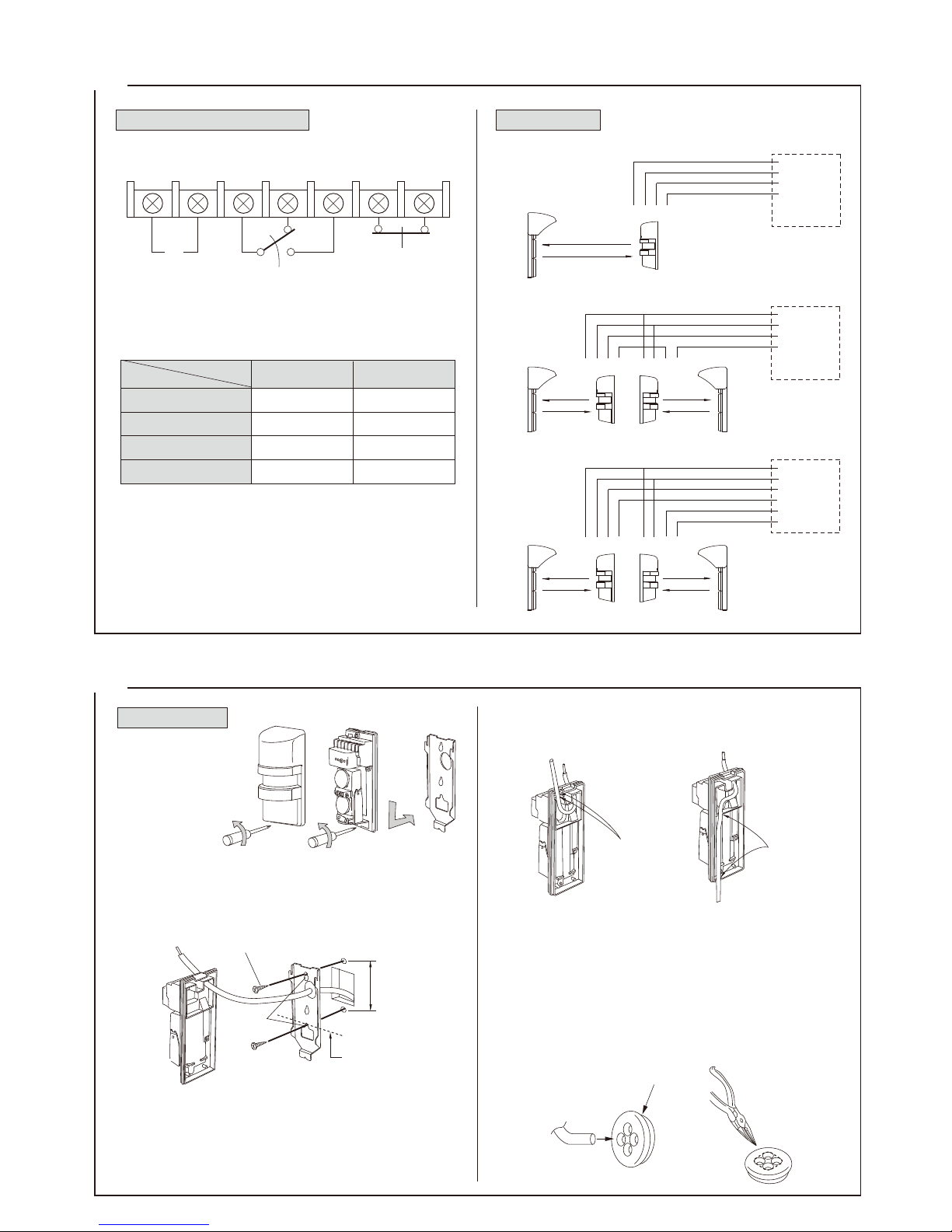
WIRING
−
+
Power
10.5V to 30VDC
(non-polarity)
Alarm
NC
NO
COM
Alarm output
Dry contact relay
output 1c N/O-N/C
NC
Tamper output
Dry contact relay
output 1b N/O
When cover is
detached
●
Example connection 1
●
Example connection 2
●
Example connection 3
Power
Alarm
(1ch.)
Alarm
(2ch.)
Power
Alarm
signal
Power
Alarm
signal
Control panel
(12VDC)
Control panel
(12VDC)
Control panel
(12VDC)
①Remove cover from
unit and slide the
mounting plate
upwards to detach
it.
②Pull the wire through on the installation site.
③Make one hole in the grommet on the mounting plate and
pull the wire through it.
Secure the plate with 4mm self tapping screws
④When the wiring is exposed , break knockouts (2 positions)
on the rear of the unit, pull the wire through as in the gure
and attach it to the terminals on the sensor.
Wiring from
the bottom
Wiring from
the top
Knockout
Knockout
※The grommet is compatible with a wire of φ0.12" (φ3mm)
to φ0.24" (φ6mm) outer dia.
When a wire of more than φ0.24 (φ6mm) outer dia. is used,
cut off the dotted line portion on the below gure using
pliers or the like.
Then use caulking to prevent insects from entering into the
unit.
① ② ③ ④ ⑤ ⑥ ⑦
▼
▼
Wiresize
Voltage
DC24VDC12V
5,610' (1700m)
9,240' (2800m)
13,860' (4200m)
16,830' (5100m)
500' (150m)
990' (300m)
1,490' (450m)
1,815' (550m)
AWG 22 (Dia 0.65mm)
AWG 20 (Dia 0.8mm)
AWG 18 (Dia 1.0mm)
AWG 17 (Dia 1.1mm)
①②③④
①②③④ ①②③④
①②③④ ①②③④
}
}
}
}
.
.
}
}
}
.
.
●
Sensor
TERMINAL CONFIGULATION
Maximum wiring distance when two or more sets are
connected is the value above divided by the number of
sets.
●
Wiring distance
Note)
CONNECTION
WALL MOUNT
⑤After wiring is completed, adjust alignment, attach cover
and check operation.
(Note : Sealing is not required for unit surround due to
rain-proof construction.)
3.29" (82.5mm)
holes
middle point of the
sensor lenses
Self tapping screw
Pull the wire through the sensor body (back to front)
and attach it to the terminals on the sensor.
Grommet
Page 4
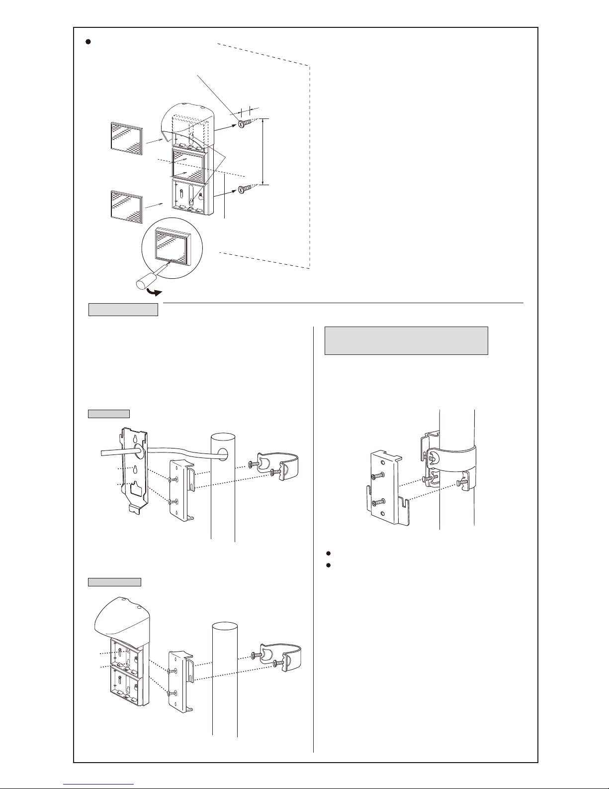
※Use outside dia. 1.50" (38mm) to 1.77" (45mm) pole.
①Insert 2pcs. of oval countersunk head screws (M4×20)
into the pole bracket with a few turns.
②Fix pole mounting plate to pole with the pole bracket.
③Fix sensor mounting plate or reector mounting plate on
the pole mounting plate with 2pcs of M4×6 screws
attached to it.
①First, x the pole mounting plate for the 1st unit.
②Let the 2nd unit pole bracket run under the 1st unit
pole mounting bracket and x the 2nd pole mounting
plate up side down.
Pole bracket
Pole bracket
Pole mounting
plate
・Follow the same procedure as ③ to ⑤ of wall mount.
・Not applicable for the reector.
5.91"
(150mm)
0.79"
(20mm)
POLE MOUNT
BACK TO BACK POLE MOUNT AND
RIGHT ANGLE POLE MOUNT
①Insert self tapping screws into the wall by about 0.79"
(20mm) and hang the reector unit back plate on them
using the holes.
Set the center of the reector unit and minddle point of
the sensor lenses at the same height, and you will nd
it easier to adjust alignment.
The reector unit should be installed uprightly and
vertically.
Make sure that the reector's front side faces the
sensor.
②Tighten the screws until the reector unit is xed
rmly.
③Fix 3 reectors to the reector unit rmly.
※For indoor use, hood is not necessary.
Sensor mounting plate
SENSOR
●
Follow the same procedure as ③ to ⑤ of wall mount.
Detach cover, and
remove mounting plate
from sensor body.
REFLECTOR
pole mounting
plate
●
Follow the same procedure as wall mount.
reflector unit
Assembly
Wall
Center of reflector
When reflector
is detached
Insert reflectors
parallel to the
reflector holder
Holes
Self tapping screw
・Reflector
Page 5
5
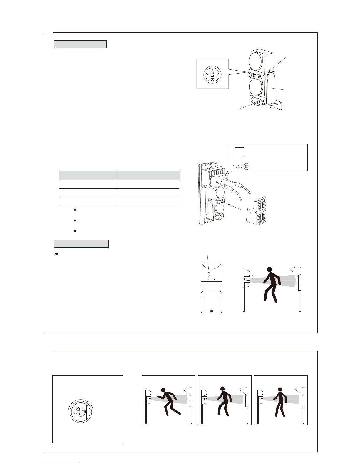
ALIGNMENT AND OPERATION
6
RESPONSE TIME
Adjust response time as follows. The unit does not detect a passing object faster than the response time setting. If the
response time is set longer, the unit does not detect human beings. Adjust to a little longer response time in a site where large
passing objects, such as birds, newspaper or falling leaves may pass through the beam path.
●
Unreasonably longer response time may cause undetection of a human being.
Response 0.05 sec. Response 0.3 sec. Response 0.7 sec.
Response time adjustment
Response time
(sec.)
(0.3)
0.7
0.05 (standard)
Run at full speed Walk with quick steps Walking
Note :
Attenuation sheet
View finder
View finder
Horizontal
adjustment
Vertical adjustment screw
Clockwise : Upward
Counterclockwise : Downward
減衰シート
Beam level (outdoor, indoor)
Best
Good
Re-adjustment
Monitor output voltage
2.6V or more
1.4to2.6V
less than 1.4V
③
①
Alarm LED
Attenuation LED
BEAM ALIGNMENT
①Face the sensor lenses to the reector with its cover
detached.
Adjust the angle of the sensor unit vertically and
horizontally by looking through the view nder placed
between the sensor lenses.
Adjust it until the center of the reector can be seen in the
middle of the view nder.
②Supply power to the sensor.
When the sensor and reector are properly installed at the
same height, alarm LED will remain OFF.
③After conrming that the alarm LED is OFF, place the
attenuation sheet on the optics of the sensor and check if
the attenuation LED is OFF.
Please note that there are two types of attenuation sheets.
(indoor use and outdoor use)
4)If the attenuation LED lights, make adjustment again
until it turns OFF.
5)Fine tuning should be done by monitoring the output
voltage using a volt meter.
・The above voltage shows the monitor output when
the lenses are covered by the attenuation sheet.
・Using the attenuation sheet and a voltmeter ensures
optimum performance of the sensor.
・After adjustment, take out attenuation sheet.
OPERATION CHECK
・After installing the sensor and making the alignment
adjustment, check the operation of the sensor with its
cover attached by looking at the alarm LED on the sensor.
①Make sure that the alarm LED is OFF.
②When the infrared beam is interrupted, the alarm LED
lights.
It indicates that the operation is normal.
The relay operates during the interruption time for a
minimum of 2 seconds.
③Walk through the infrared beam between the sensor and
the reector and make sure that the alarm LED lights up
and then goes off.
Note :
(See the table below.) until obtaining the peak voltage.
Make sure the light turns off(②)
Make sure the light turns off(③,④)
Reflector
Sensor
Alarm LED
volt meter
Page 6
7
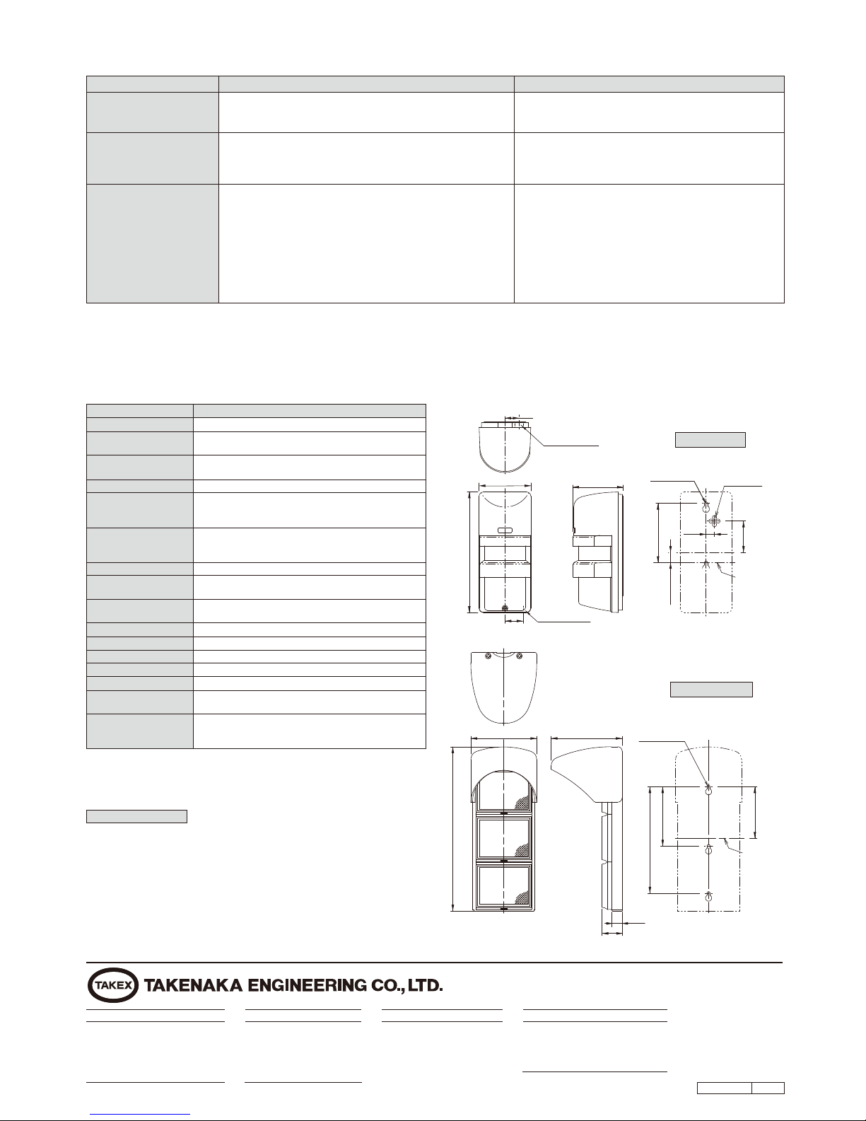
TROUBLESHOOTING
8
EXTERNAL DIMENSIONS
9
SPECIFICATIONS
Symptom
Possible cause Remedy
1) No power supply.
2) Bad wiring connection or broken wire, short.
3) Beam is reected on another object and sent into the receiver.
LIMITED WARRANTY
1) Turn on the power supply.
2) Check wiring.
3) Remove the reecting object or change beam direction.
Alarm LED does not light
when the beam is broken.
Alarm LED continues to
light.
1) Beam alignment is out.
2) Shading object between sensor and reector.
3) Sensor cover or reector are soiled.
1) Check and adjust again.
2) Remove the shading object.
3) Clean them with a soft cloth. (Except the cover)
1) Bad wiring connection.
2) Change of supply voltage.
3) Shading object between sensor and reector.
4) A large electric noise source, such as power machine, is located
nearby sensor.
5) Unstable installation of sensor and reector.
6) Sensor cover or reector are soiled.
7) Improper alignment.
8) Small animals may pass through the beams.
1) Check again.
2) Stabilize supply voltage.
3) Remove the shading object.
4) Change the place for installation.
5) Stabilize.
6) Clean them with a soft cloth.
7) Check and adjust again.
8) Set the response time longer. (Do not use this setting
where an intruder can run at full speed through the beam.)
Intermittent alarm
●
Specications are subject to change without notice.
Knockout
Knockout
□0.47"×0.28"
(□12mm×7mm)
□0.47"×0.28"
(□12mm×7mm)
2-φ0.16"
(φ4)
3-φ0.16"
(φ4)
Wiring lead
Middle point
of the sensor
lenses
Center of
the reflector
0.79"(20mm)
3.29"
(83.5mm)
3.29"
(83.5mm)
2.85"
(72.5mm)
0.57"
(14.5mm)
1.73"
(44mm)
0.47"
(12mm)
2.87"(73mm)
2.81"(71.5mm)
3.66"(93mm)
3.94"(100mm)
0.98"
(25mm)
0.59"(15mm)
1.12"(28.5mm)
6.69"(170mm)
9.11"(231.5mm)
5.91"(150mm)
Model
Detection system
Protection distance
Supply voltage
Current consumption
Alarm output
Tamper output
Response time
Alarm LED
Attenuation LED
Functions
Ambient temperature range
Mounting positions
Wiring
Weight
Appearance
Accessory
PR-11BE
Near infrared beam interruption system (reective)
Outdoor 3.3 to 36' (1 to 11m)
Indoor 3.3 to 49' (1 to 15m)
10.5V to 30V DC (Non-polarity)
(Class 2 powered device)
55mA or less
Dry contact relay from N/O-N/C
Contact capacity : 30V (AC/DC) 0.5A or less
Relay operation : Interruption time (minimum 2 seconds)
Dry contact relay 1b (N/C)
Action : Activated when cover is detached.
Contact capacity : 30V (AC/DC) 0.5A or less
0.05sec to 0.7sec. (Adjustable by potentiometer)
Red LED
ON : when an alarm is initiated
Red LED
ON : when beam is attenuated
Monitor output
-13°F to + 140°F (-25℃ to +60℃)
Outdoor/Indoor
Terminals
Sensor : 15oz (430g) Reector : 17oz (490g)
Sensor : PC resin(wine red)
Reector : acrylic resin (clear), AES resin (black)
Self tapping screw φ4×30 : 4
Attenuation sheet : 2pcs
(for outdoor, for indoor)
REFLECTOR
SENSOR
Check the operation of the unit once a week.
When the cover is stained, just wash it away with waters.
Never clean it with a cloth otherwise it could damage the photocatalytic antifouling lm attached on the sensor cover.
The lm is designed to prevent attenuation of the infrared caused by the stain or the waterdrop from torrential rain.
*Do not clean the cover with a cloth. Just wash it away with water.
〈Daily check〉
〜〜〜〜〜〜〜〜〜〜〜〜〜〜〜〜〜〜〜〜
〜〜〜〜〜〜〜〜〜〜〜〜〜〜〜〜〜〜
CAUTION : The suitability of this device with respect to reducing casualty
hazards or providing a safety function is to be determined in the end-use
application.
No.05-097 1608
In Japan
Takex America Inc.
4/15 Howleys Road, Notting Hill,
VIC, 3168
Tel : +61 (03) 9544-2477
Fax : +61 (03) 9543-2342
Takenaka Engineering Co., Ltd.
83-1, Gojo-sotokan,
Higashino, Yamashina-ku,
Kyoto 607-8156, Japan
Tel : 81-75-501-6651
Fax : 81-75-593-3816
http : // www. takex-eng. co. jp /
Takex America Inc.
151 San Zeno Way
Sunnyvale,
CA 94086, U.S.A
Tel : 408-747-0100
Fax : 408-734-1100
http : // www. takex. com
Takex Europe Ltd.
Aviary Court, Wade Road,
Basingstoke, Hampshire. RG24 8PE, U.K.
Tel : (+44) 01256-475555
Fax : (+44) 01256-466268
http : // www. takex. com
In the U.S. In the U.K.
In Australia
TAKEX products are warranted to be free from defects in material and
workmanship for 12 months from original date of shipment. Our warranty does
not cover damage or failure caused by natural disasters, abuse, misuse,
abnormal usage, faulty installation, improper maintenance or any repairs other
than those provided by TAKEX. All implied warranties with respect to TAKEX,
including implied warranties for merchantability and implied warranties for
tness, are limited in duration to 12 months from original date of shipment.
During the Warranty Period, TAKEX will repair or replace, at its sole option,
free of charge, any defective parts returned prepaid. Please provide the model
number of the products, original date of shipment and nature of difculty being
experienced. There will be charges rendered for product repairs made after our
Warranty Period has expired.
 Loading...