

Page 1

①
Instruction Manual
2
1
PARTS DESCRIPTION
PRODUCT DESCRIPTION
FS-5000E
FLAME SENSOR
Mounting box
Push rivet
Screw
Wiring hole
Accessories
Tapping screw
φ6×30 (4 pcs.)
Tapping screw
φ4×8 (1 pc.)
Combining band
(1 pc.)
Area mask seal (1 pc.)
Instruction manual
Detection
window
Operation
LED (red)
Memory indication
LED (yellow)
Bolt
Mounting base
This sensor is not fire-alarm device.
See Instruction Manual.
3
2
1
Symmetry
VERTICAL
HORIZONTAL
0
°
Down 50
°
Down 50
°
Down 30
°
Down
30°
9135-33
!
*
*
Do not touch the
detection window
barehanded.
Detection
window
3
2
1
Down 60°
0
°
20°
20°
40°
40°
50°
40°
50°
20°
20
°
40
°
0
°
D
B
C
A
AREA MASK SEAL
&
UPPER
0°
Ball lock
Adjustment volume
Screw
Adjustment box
CAUTION CAUTION
*
Do not install in locations that cannot withstand the
weight of this product. It may fall and cause an accident.
*Do not disassemble or modify this product. It may cause
re, electric shock, etc.
*
Follow the voltage of the indicated power supply.
lncorrect voltage may cause re, electric shock, etc.
*Do not connect equipment that exceeds the indicated
output capacity. It may cause re.
We appreciate your purchase of a TAKEX ame sensor. This sensor will provide long and dependable service when properly installed.
Please read this Instruction Manual carefully for correct and effective use.
Please note : This sensor is designed to detect ames and to initiate an alarm ; it is not a re-preventing device.
TAKEX is not responsible for damage, injury or losses caused by accident, theft, Acts of God (including inductive
surge by lightning), abuse, misuse, abnormal usage, faulty installation or improper maintenance.
Flame sensor FS-5000E immediately detects ultraviolet rays contained in ames and activates the external output.
It can be installed either indoors or outdoors. By selecting the set up from the 8 levels that is suitable to the environment
where the sensor is installed, it will reduce the possibility of false detections of other kinds of ultraviolet rays.
Also there are many convenient functions such as Output Time Set Up, Day/Night Time Discernment Function, and Alarm
Memory Function. It can be used widely as early detector of incendiary re, smoking in prohibited areas etc.
Page 2

②
3
PRECAUTIONS
●
●
PRODUCT CLASSIFICATION
●
●
●
●
●
●
●
The detection window is made of specialized glass and it is fragile.
●
●
●
●
OBJECTS TO BE DETECTED
OTHERS
*
INSTALLATION
●
*Halogen lamp
*Electric discharge lamp such as
a mercury lamp
*Electric sterilizer lamp
*Welding sparks
*Electric sparks (caused by
motor, pantograph)
*Sunlight
*Electric discharge from
lightning
*Radiation
*High electrical field
Possible cause of false alarm. Do
not install the sensor near the
followings:
Flames which can not be
detected:
*Flames through glass or
transparent resin
*Lit portion of cigarette
*Burning charcoal or
briquet
*Electric stove
*Burning object without
flames
INSTALLED
OUTDOORS
DETECTION
TIMER
SENSITIVITY
1 sec.: Not recommended
6 secs. or more: OK
H: Not recommended
L: OK
10°
10°
Adjustable angles
NG
NG
NG
OK
OK
OK NG
(The factory set is 1 sec.)
The unit is designed for ceiling and wall mounting.
Please make sure that the base surface is protected with
reinforcements. In case of installation on concrete or gypsum
board, please use anchors and screws suitable for the material.
Do not touch the detection window barehanded.
Oil from hands may cause low sensitivity. Wipe the detection
window with a soft cloth with alcohol if it is dirty.
After installation, wipe again when necessary.
This sensor detects ultraviolet rays at a very sensitive level, so
it will possibly detect objects other than ames.
In addition, this sensor does not detect burning objects that are
not producing ames.
Keep the detection window
straight and the adjusting
part at the bottom.
Keep the sensor angle somewhere between completely horizontal and vertical when installed outdoors.
Do not pour water directly on the sensor, as it is rain proof, not
water tight.
Do not install the unit in locations where high amounts of
steam stagnate (bathrooms etc.).
Do not install the unit in areas where the temperature is under
-20°C (-4°F) or over +50°C (+122°F).
Do not install the unit in an environment subject to electrical
noise or intense vibration.
After adjusting the angle, tighten the screws and bolts to
prevent the unit from falling and to maintain resistance to
rain.
A high installation location is recommended to prevent vandalism. (over 2.5m)
This product is for installation on walls, ceilings, and under
eaves. Use the optional attachment for installation at uneven
places.
●
●
●
●
●
●
●
●
●
●
This sensor is designed detect ultraviolet rays contained in
ames and to output a signal. This unit is not a re-preventing
device. It will not detect smoke or heat.
TAKEX is not responsible for damage, injury or losses caused by
re, accident, calamity, natural disasters (including inductive
surge by lightning), abuse, misuse, abnormal usage, faulty installation or improper maintenance.
Ultraviolet rays are invisible. They may be emitted by
unexpected objects. Set the sensitivity to "L" and the detection
timer to the next longer time when the sensor does not operate
properly, in case of generating an alarm when there is no
ame or when none of the "possible causes of false alarm"
listed below are present, etc.
In the case of an explosion, the sensor may be damaged before
detecting ames.
Sparks from neighboring areas where welding is being
performed
may cause false detection.
If a person who is undergoing isotope therapy (radioiodine
therapy) comes near the unit, he/she may emit radiation
sufcient to trigger the sensor.
Set the sensitivity to "L" in such a case.
In cases where the detection window is covered with frost, ice,
etc., the sensitivity will become very low and the sensor may not
detect properly.
There are many other ultraviolet rays outdoors that may cause
unexpected detection.
Therefore, it is recommended that the detection timer is set to
longer than 6 secs. when the unit is installed outdoors.
The sensitivity will decrease in case of rain or snow in the
detection area.
Do not install the unit in locations where sparks or ames are
usually used (kitchen, incinerator, etc.).
Do not install the unit in locations subject to severe shock or
electric noise.
Do not install the unit in locations where a shield object (glass,
transparent resin, etc.) is in front of the sensor.
Do not install the unit near
railways. Sparks from
pantographs may cause false
detection.
Do not install the unit near
high voltage power lines.
Sparks from pylons may
cause false detection.
Page 3

③
4
DETECTION AREA
*
180°
movable
180°
movable
loosen
tighten
BALL
LOCK
BALL LOCK
BOLT
90°
movable
*
●
●
*
*
1. Detection Area
●
There are many ultraviolet rays outdoors that may cause unexpected detection. In case there are objects in the area that cause
unexpected detection and that cannot be avoided by adjustment, use the accessory "area masks" to cover the area.
●
There are 6 horizontal and 4 vertical masks. These 2 types can also be used in combination.
AREA MASKING
AREA MASK SEAL
HORIZONTAL
AREA MASK SEAL
VERTICAL
15°
(2)
(1)
(3)
(3)
(A)
(B)
(C)
(D)
See Instruction Manual.
3
2
1
Symmetry
VERTICAL
HORIZONT
AL
0°
Down 50
°
Down 50°
Down 30
°
Down
30
°
9135-33
!
*
*
Do not touch the
detection window
barehanded.
Detection
window
3
2
1
Down 60
°
0
°
20°
20°
40
°
40
°
50
°
40°
50°
20°
20
°
40°
0
°
D
B
C
A
AREA MASK SEAL
&
UPPER
0°
See Instruction Manual.
3
2
1
Symmetry
VERTICAL
HORIZON
TAL
0°
Down 50
°
Down 50
°
Down 30
°
Down
30
°
9135-33
!
*
*
Do not touch the
detection window
barehanded.
Detection
window
3
2
1
Down 60°
0
°
20°
20°
40
°
40
°
50
°
40°
50
°
20°
20°
40°
0
°
D
B
C
A
AREA MASK SEAL
&
UPPER
0°
66'
(20 m)
49'
(15 m)
33'
(10 m)
16.5'
(5 m)
16.5'
(5 m)
33'
(10 m)
49'
(15 m)
66'
(20 m)
16.5'
(5 m)
33'
(10 m)
49'
(15 m)
66'
(20 m)
83'
(25 m)
16.5'
(5 m)
33'
(10 m)
49'
(15 m)
66'
(20 m)
83'
(25 m)
100'
(30 m)
16.5'
(5 m)
33'
(10 m)
49'
(15 m)
66'
(20 m)
83'
(25 m)
100'
(30 m)
[SIDE VIEW]
[TOP VIEW]
15°
GAS FLAME OF
LIGHTER
2.75" (7cm)
GAS FLAME OF
LIGHTER
2.75" (7cm)
FLAME OF
N-HEPTANE
23.62" (60cm)
FLAME OF
N-HEPTANE
23.62" (60cm)
66'
(20 m)
49'
(15 m)
33'
(10 m)
16.5'
(5 m)
16.5'
(5 m)
33'
(10 m)
49'
(15 m)
66'
(20 m)
16.5'
(5 m)
33'
(10 m)
49'
(15 m)
66'
(20 m)
83'
(25 m)
100'
(30 m)
16.5'
(5 m)
33'
(10 m)
49'
(15 m)
66'
(20 m)
83'
(25 m)
100'
(30 m)
16.5'
(5 m)
33'
(10 m)
49'
(15 m)
66'
(20 m)
83'
(25 m)
2. Area adjustment
●
●
After afxing the area mask, check operation
of the sensor.
●
Wear gloves and do not touch the detection
window barehanded.
The upper detection area is limited to avoid sun ray inuence and other unexpected detectable objects remotely located.
The detection distance depends on the size and time of aming.
The bigger and longer continuous ame is more apt to be detected.
The smaller and shorter the ame continues, the narrower the detection area gets.
[Sensitivity: H]
【TOP VIEW】Sensitivity: H
【SIDE VIEW】Sensitivity: H
The area adjustment in wide angle allows the
sensor to beinstalled in various locations.
Loosen the bolt and ball lock and refer to
"3. PRECAUTIONS" when installing.
Do not forget to tighten it when nished.
Keep the detection area downwards to avoid
sun ray inuence and other unexpected detectable
objects remotely located when installing outdoors.
Afx the area mask on the edge of the
detection window while holding the tab, and
tear off the tab after afxing the area mask.
Flame that burns the ammable liquid "n-heptane" that is a component of gasoline.
Takenaka uses this ame as the standard for measurement.
Flame size is variable, so the above detection areas are average.
[N-HEPTANE FLAME] :
*
SENSITIVITY "L" : The ditection area becomes approx 50% of above area.
Page 4
④
5
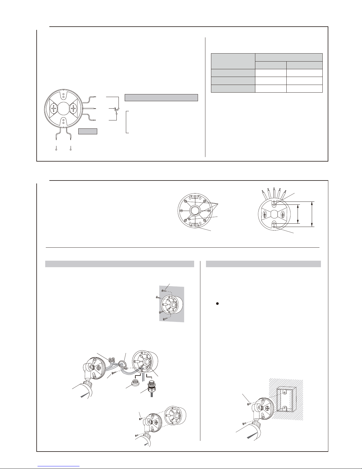
WIRING
COM
N.C.
N.O.
Mounting hole
(knock out)
United band
hole
Push rivet
Screw
Wiring hole
MOUNTING BOX
MOUNTING BASE
66.7mm
2.63
"
3.29"
83.5mm
φ6×30Tappingscrew
Screw
Wall
Screw
(1) Attention
(2) Wiring Connection
Operation (selectable) :
Contact capacity : 30V (AC/DC)
0.5A or less
detection time + off delay operation
approx. 2 secs. ~ approx. 1 min.
or
detection time + off delay operation
approx. 5 secs. ~ approx. 10 mins.
Dry contact relay output Form C
Power
10V to 30VDC
(non-polarity)
35mA or less
6
The following wiring and installation can be done. Follow the procedures.
INSTALLATION
*
*
*
EXPOSED WIRING
BUILT IN WIRING
(1) Fix to the surface
(1)
(2)
(2)
(3)
(3)
(4)
blue
black red
yellow
white
【Wiring distance】
Power supply
Size of wire used
DC12V DC24V
1310'(400m)
3120'(950m)
5250'(1600m)
980 0'(300 0m)
226 00'(6900m)
38000'(11600m)
NOTE : 1)
2)
0.75mm2(φ0 . 9 3 mm)
1.25 mm
2
(φ1.3mm)
0.3mm
2
(φ0 .6 5 mm)
Maximum wiring distance, when two or
more sets are connected, is calculated by
dividing the above value by number of sets.
The signal line can be wired in the
distance of up to 3,000ft. (1,000m) with
(dia. 0.65mm) telephone wire.
Select the most suitable installation place and way
according to the purpose. (Refer to "3. PRECAUTIONS" and the following)
Take off the 2 screws, mounting base, mounting box.
(Wiring leads are contained in the mounting base.)
Wire and instal the sensor. (Refer to "5. WIRING"
and the following)
Set up temporary and conrm the area and operation.
①Make a hole through the 4 mounting holes
(knock outs) by a driver etc.
②Fix the mounting box by the 4 φ6×30
tapping screws to the surface.
Fix the mounting base tightly to the
mounting box by the 2 screws.
Follow the "5. (2) Wiring connection" for wiring. To avoid direct
pressure to the knot, combine the wiring by the accessory Combining Band and x it to the inside of the box by φ4×8 tapping screw.
Preparement (not necessary for following case)
[The mounting base ts 83.5mm and 66.7mm type
built in switch box. However, it needs adjustment
for the following case.]
◎66.7mm type (beginning set up : 83.5mm)
・Push out the 2 push rivets from the back side of
the mounting base and put them into the 2 holes
on the outside.
Follow the "5. (2) Wiring connection" for wiring.
Fix the mounting base tightly to the attachment
box by the 2 screws.
Give rain proof treatment such as calking to the top
and side of the mounting base. (It may not stick
according to the surface condition.)
*Use optional equipments for other installation.
Take off the lid of the wiring hole on the bottom
of the mounting box and pass the wiring
through. (Conduit tube wiring is possible for
the wiring hole is conduit tube screw G16.)
(4)
Turn off power when installing. Hot line work will cause electric shock
and damage.
Lead wiring is required. Follow the proper way.
The wiring lead is contained in the mounting base. Take off the screw,
mounting base, and mounting box when installing.
[1]
[2]
[3]
[4]
Fixinghole
Conduitbushing
Wireconnection
Combiningband
Tappingscrew
Lid
Page 5
⑤
7
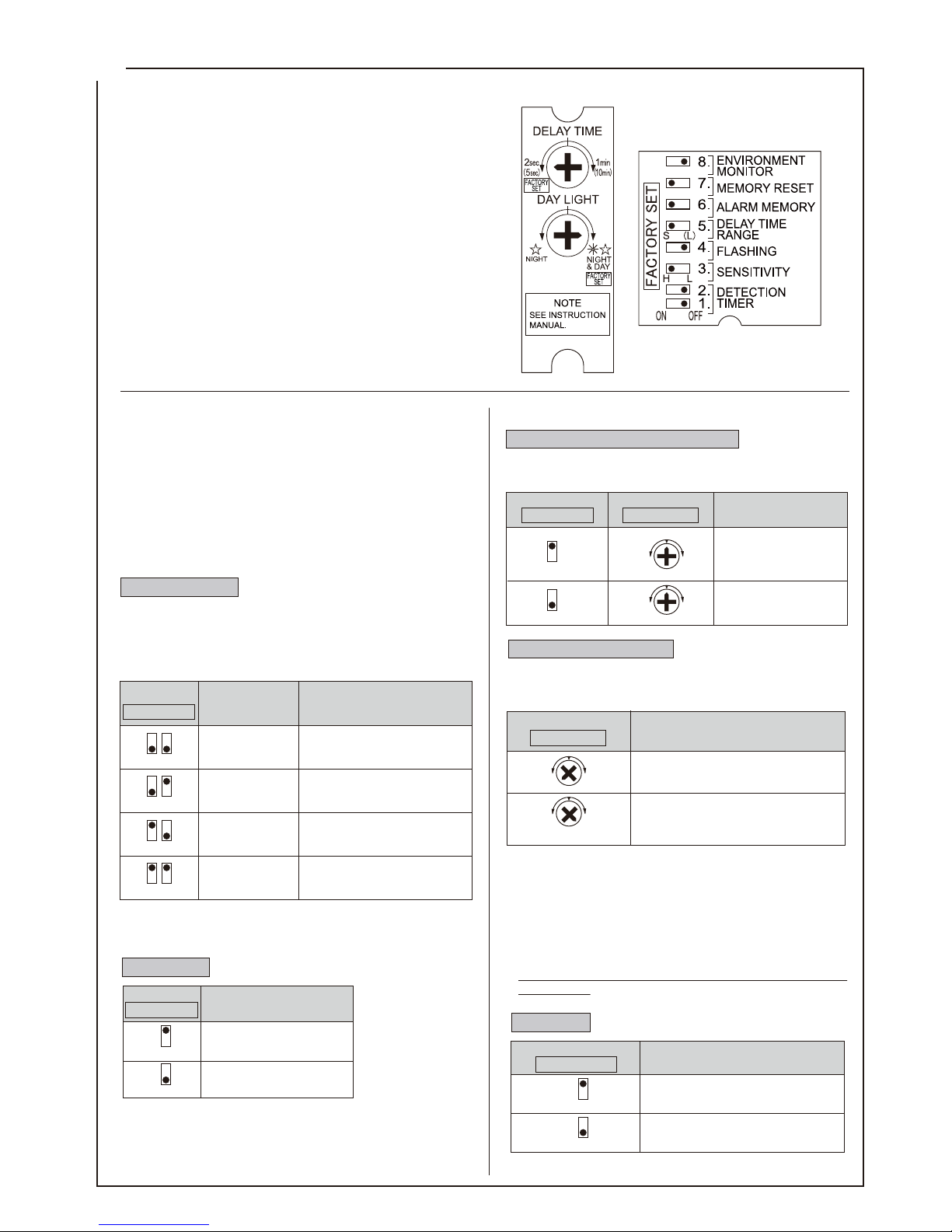
OPERATION AND FUNCTION
ADJUSTMENTVOLUME
ADJUSTMENTBOX
Flashing is useful to threaten and notice incendiarism.
*
*
*
Delay time (Operation time adjustment)
Day light (Operation mode)
*
*
*
*
(1) Operation
(2) Mode Setting
①Detection Function ②
Output function
Detection timer
1 2
OFF OFF
1 2
OFF
ON
1 2
ON
OFF
1 2
ON ON
The following 4 levels are selectable.
ADJUSTING BOX
DETECTION TIME
PURPOSE/EXAMPLE
DETECTION TIMER
(outputs when flames for
more than the below time)
Flashing
1sec.
6secs.
15secs.
30secs.
*
*
*
Sensitivity
Flame of lighter/match detection at
non-smoking areas. [Factory set]
In case of uncertain operation on
the above two.
Fire detection
Fire detection in uncertain
environment.
3
H
3
L
ADJUSTING BOX
SENSITIVITY
SENSITIVITY
H : 100%
[Factory set]
L : 50%
OUTPUT CONDITIONS
(circumference brightness)
ADJUSTING VOLUME
DAY LIGHT
Output only night time
Output both day/night time
[Factory set]
5
(S)
(short)
(long)
(L)
5
(5 sec.)
(10 min.)
(2 sec.)
(1 min.)
ADJUSTING BOX
DELAY TIME RANGE
OPERATION TIME
(adjustment limit)
ADJUSTING VOLUME
DELAY TIME
approx. 2 secs.
~approx. 1 min.
Factory set
: approx. 2 secs.
approx. 5 secs.
~approx. 10 mins.
4
ON
NIGHT
NIGHT
&DAY
4
OFF
ADJUSTING BOX
FLASHING
OUTPUT TYPE
Continuous output
[Factory set]
Repetition of flashing
(0.5 sec. output, 0.3 sec. stop)
[
[
The following two output types are selectable.
The operation LED (red) will light and start output when the
sensor detects ame (ultraviolet ray) for the set up time (1 sec.,
6 secs., 15 secs., 30 secs.,) and moreover when the environment
is darker than the [operation mode] set up.
In case it still keeps aming, it will connue the above operation
LED (red) lighting and output. After the ame goes out, the
operation LED (red) lighting and output (off delay) will stop
according to the [delay time range] (2 secs. 〜10mins.).
The following settings and functions are selectable for detection
and output.
Use the dip switch in the adjustment box and adjustment
volume which is on the bottom of the sensor.
・The adjustment volume can be turned by coins.
Do not turn strongly, it may cause damage.
This product detects ultraviolet ray included in ames and
outputs an alarm. Outdoor installation would cause much more
false detection than indoor installation, as there are many other
ultraviolet ray factors and few shielding objects.
The 8 selectable sensitivity levels combined by 2 sensitivity set
ups and 4 detection timer set ups are made to prevent false
detection in such uncertain conditions outdoors. Select the set
up that suits most the environment and purpose.
When the sensor does not operate properly, set the sensitivity to
"L" and detection timer to the next longer time.
This function sets up the minimal aming time to detect.
It outputs an alarm when the aming continues more than the set
up time. It will not output an alarm when the ame goes out
before the set up time.
The detection distance for "L" is half of that for "H", when
detecting same ame.
When there is uncertain operation at "H", change the sensitivity to "L".
For outdoor use, "L" is recommended.
The alarm may delay when the strength of ultraviolet ray is low.
Intermittent ultraviolet ray will not be detected.
Timer set up with 6 secs. or more is recommended for outdoor installation.
This function set up the size of ame (the
strength of ultraviolet ray) to detect.
For subtle set up, adjust the volume when the circumference
is at the requested light level.
Even setting up for night time mode, it may not output a signal
when the circumference is bright with lightings etc. In that
case, turn the volume to right until it outputs a signal.
The "output only night time" function is convenient to detect
only at night time in the locations that have other ultraviolet
ray factors at day time.
Please set "off" in "Alarm memory function" when setting up
this function.
The following output will be produced only when the circumference is darker than the set up. (day / night time discernment
function) Set up according to purpose.
The output time for day time is off delay of detection time + set
up time. There are following selections.
Page 6
⑥
*
*
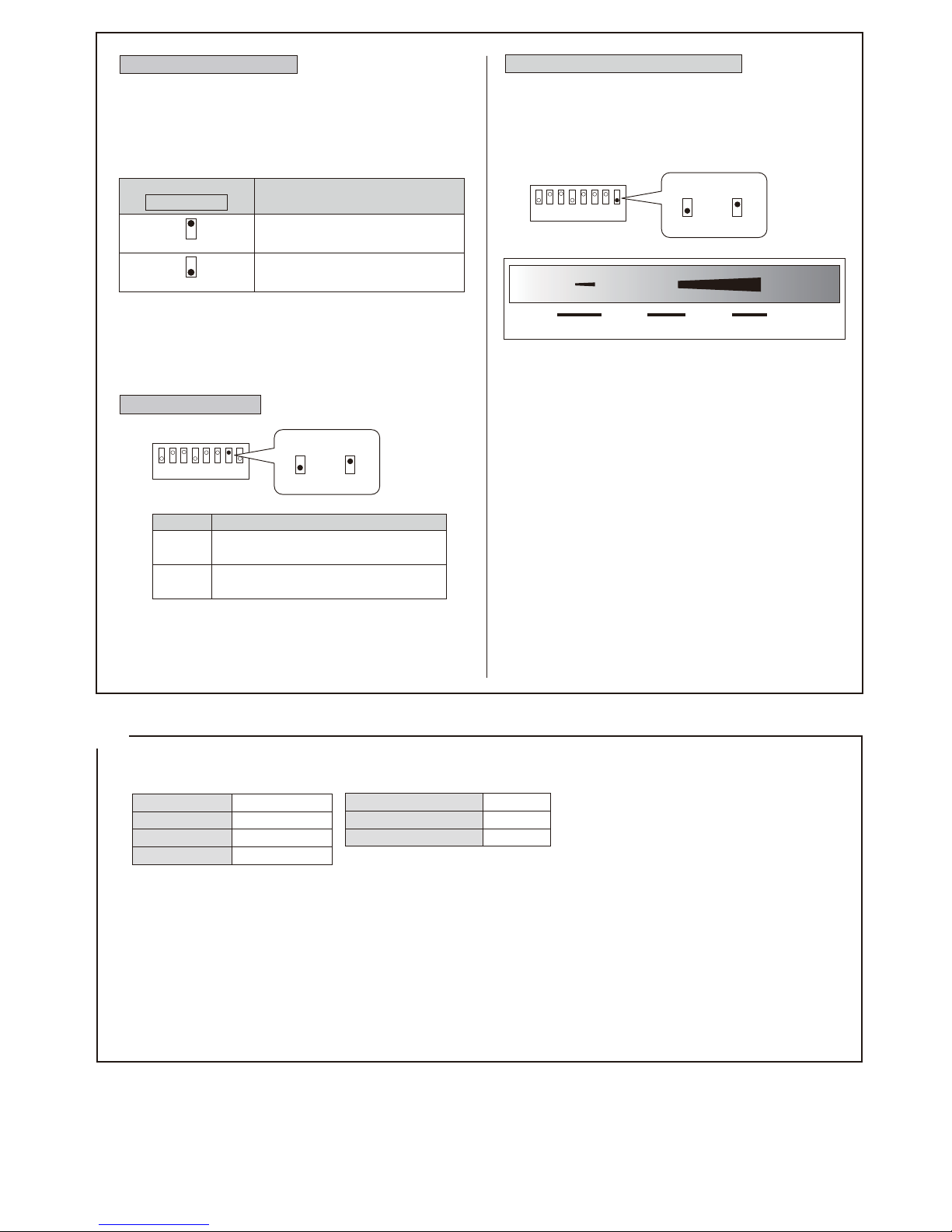
Alarm Memory Function
**
*
*
*
*
8
OPERATION CHECK
Check operation after wiring and installation.
(1) Detection area
(2) Operation
6
ON
6
OFF
ADJUSTING BOX
ALARM MEMORY
MEMORY
Does not indicate
*
*
Detection timer
Sensitivity
Delay time
Day light
Alarm memory function
Memory auto reset
Environment monitor
1 sec.
H
2 secs.
Night & Day
ON
ON
OFF
Environment monitoring function
Noultraviolet
sourcefor
falsealarm.
Alittleultraviolet
sourcefor
falsealarm.
Muchultraviolet
source
forfalsealarm.
LEDOFF
Blinking
(slow)
Blinking
(fast)
LEDlightsON
8
88
OFF ON
The strength is showed by operation LED (red).
7
Memory auto reset
(Factoryset:On)
Blinking(3minutes)
Lighton(Untilresettingbymanual)
77
OFF ON
ON
OFF
Blinking(3minutes)
MemoryLED(yellow)Setting
Lighton(Autoresetafter47minuteslater)
Choose the set up according to the purpose and environment.
Activate the sensor again and check the operation LED (red), and connected machines and tools.
Set up the area angle reffering to the
"4. 1. Detection area" picture. Put power on.
Turn on a lighter more than 1 sec. within the detection area. Check the angle and size of area by operation LED (red) and
connected machines and tools.
In case it includes unnecessary areas, adjust it by changing angle or masking the area.
In case of resetting this function during blinking and lighting,
turn the power off and on again.
(power on reset operation)
Set up for area check. (Factory set)
Indicates [Factory set]
※
Manual reset : Power supply off and on again or "Alarm memory
function" off.
This function monitors the strength of nuisance by ultraviolet
in installed environment to check whether there is a cause of
false alarm.
When the performance of this sensor becomes unstable, please
use this function to check the strength of ultraviolet.
(Factoryset:OFF)
This function enables identication of individual sensors in
multiple sensor conguration.
After raising an alarm, the memory indication LED (yellow)
blinks for 3 minutes and then lights for 47 minutes.
When an alarm is caused again during the lighting, it will light
for another 47 minutes. <re-trigger operation>
The operation LED (red) may be "light on" 2~3 times per 1
minute in even normal environment. In case of more frequent
lighting, there may be a nuisance ultraviolet source in the site.
Therefore, please set sensitivity "L" and detection timer more
than "6 secs".
In case operation LED (red) lights on or blinking continue more
than set detection timer, Please adjust sensitivity "L" and
detection timer more than above operation LED (red) duration
time.
The environment of ultraviolet is not always equable.
It may fluctuate by varied factors.
When the performance of this flame sensor becomes unstable
after installation, please adjust sensitivity to downward and
detection timer to the next longer time.
The alarm signal outputs at setting level (sensitivity, detection
timer) even environment monitoring function is "ON".
1:
2:
Page 7
⑦
㈯
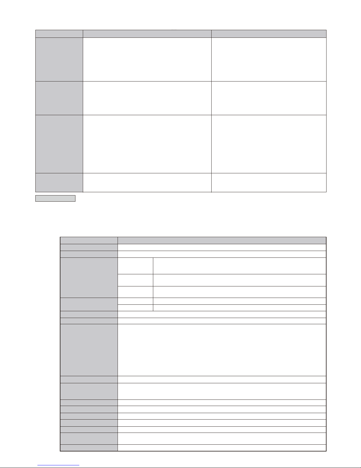
PRODUCT NAME
FLAME SENSOR
FS-5000E
Ultraviolet rays detection (Detected wave length <185 to 260nm>)
33ft. (10m) [Gas Flame of Lighter in front of sensor : approx. : 2.75”(7cm)]
100ft. (30m) [Flame of N-heptane on fire plate 15cm×15cm : approx. : 23.62”(60cm)
*The flame size is rough.
Vertical : approx. 75° (upward :15°)
Horizontal : approx. 100° (downward :60°)
Vertical : downward 90° (horizontal-vertical)
Horizontal : 180°
H (100%), L (50%) [selectable by switch]
1sec., 6secs., 15secs., 30secs. [selectable by switch]
10V to 30VDC (non-polarity)
35mA or less
Dry contact relay Form C (alarm : open/close)
Contact capacity : 30V (AC/DC) 0.5A or less (resistance load)
Operation time : The following are selectable
Detection time + off delay operation approx. 2 secs. - 1 min.
Detection time + off delay operation approx. 5 secs. - 10 mins.
Output operation : The following are selectable
Same time as above continuous output
Same time as above intermittent output (Flashing)
Operation mode (day/night time discernment function)
: 5 lux (night time operation) - ∞ lux (day time operation) adjustment volume
LED(yellow) blinking and lights on /or LED disable. [selectable by switch]
Operation LED (red) : synchronous dry contact relay
Memory indication LED (yellow) : After blinking for 3 minutes and auto reset after 47 minutes
or reset by manual
Lead wiring, power supply : 2 / dry contact : 3
−
4°F to +122°F (−20℃ to +50℃)
Indoor, Outdoor
approx. 19.3 oz (550g)
Sensor part : PC resin (white), Adjustment, mounting part : AES resin (white)
Tapping screw φ6× 30 (SUS) : 4 pcs , Tapping screw φ4× 8 (SUS) : 1 pc.
Band : 1 pc. Area mask seal : 1 pc.
Pole attachment (for the end) : BP-01, Pole attachment (for the middle) : BP-02, Vise : BV-03
10
SPECIFICATIONS
TROUBLE CHECK
9
TROUBLE SHOOTING
Completely inactive
CORRECTIVE ACTION
Sometimes inactive
The LED lights but the
connected device
inactivates
Activate without flame
Maintenance
When the sensor is dirty, clean the cover with a soft cloth moistened with a small amount of cleaning solution.
Do not use chemicals such as thinner or alcohol. Check operation once a week.
Do not fail to check operation whenever furniture in the vicinity is moved.When the battery is low, change it for a new one immediately.
If the battery is not changed, the sensor may not operate.
OPTIONAL
ACCESSORIES
APPEARANCE
WEIGHT
INSTALLATION
AMBIENT TEMP. RANGE
WIRING
LED
ALARM MEMORY
*
*
*
*
ALARM OUTPUT
POWER CONSUMPTION
POWER SUPPLY
Detection timer
SENSITIVITY
ADJUSTMENT
Sensitivity
Adjustment
range
Angle
Distance
DETECTION AREA
DETECTION SYSTEM
MODEL NO.
・Correct supply or replace broken wiring
・Correct supply or replace broken wiring
・Remove the interrupting object
・Re-adjust the detection area set up
(Refer to "4. DETECTION AREA")
・Re-adjust the operation mode
(Refer to "7. OPERATION AND FUNCTION")
・Re-adjust the detection timer set up
・No power supply (Broken or improper wiring)
・Low voltage
・Interrupting object in front of detection area (Including glass
)
・Improper detection area set up
(Including detection distance)
・Improper operation mode set up
・Improper detection timer set up
・Improper detection area set up
(Including detection distance)
・Improper operation mode set up
・Detection window soiled
・Improper detection timer, sensitivity set up
・Re-adjust the detection area set up
(Refer to "4. DETECTION AREA")
・Re-adjust the operation mode
(Refer to "7. OPERATION AND FUNCTION")
・Wipe with soft dry cloth
・Re-adjust the detection timer, sensitivity set up
・Unstable power supply
・Large electrical noise source such as radio station or wireless
station nearby
・Unexpected ultraviolet ray nearby
(Refer to "3. PRECAUTIONS")
・Sparking object such as welding construction site, railway
pantograph nearby
・Correct power supply
・Relocate the sensor
・Remove the object / Relocate the sensor / Adjust the
angle / Mask the area by seal / Set up sensitivity to "L" /
Set up detection timer to the next longer time.
(Refer to "4. DETECTION AREA")
・Relocate the sensor / Adjust the angle / Mask the area
by seal / Set up sensitivity to "L" / Set up detection timer
to the next longer time.
(Refer to "4. DETECTION AREA")
・Poor contact output connection or broken wire
・Improper output connection
・Improper connected units
・Check the wiring or connection
・Check the output terminal by tester etc.
・Check the connected units
●
●
●
●
●
●
●
●
●
●
●
●
●
●
●
●
● ●
●
●
●
●
●
●
●
●
●
●
●
●
●
●
●
●
Page 8
⑧
Limited Warranty :
TAKEX products are warranted to be free from defects in material and workmanship for 12 months from original date of shipment. Our warranty does not cover
damage or failure caused by natural disasters, abuse, misuse, abnormal usage, faulty installation, improper maintenance or any repairs other than those provided
by TAKEX. All implied warranties with respect to TAKEX, including implied warranties for merchantability and implied warranties for tness, are limited in
duration to 12 months from original date of shipment. During the Warranty Period, TAKEX will repair or replace, at its sole option,free of charge, any defective
parts returned prepaid. Please provide the model number of the products, original date of shipment and nature of difculty being experienced. There will be
charges rendered for product repairs made after our Warranty Period has expired.
No.04-990 1406
In Japan
Takex America Inc.
4/15 Howleys Road, Notting Hill,
VIC, 3168
Tel : +61 (03) 9544-2477
Fax : +61 (03) 9543-2342
Takenaka Engineering Co., Ltd.
83-1, Gojo-sotokan, Higashino,
Yamashina-ku, Kyoto 607-8156, Japan
Tel : 81-75-501-6651
Fax : 81-75-593-3816
http : // www. takex-eng. co. jp /
Takex America Inc.
3350, Montgomery Drive
Sant Clara, CA 95054, U.S.A.
Tel : 408-747-0100
Fax : 408-734-1100
http : // www. takex. com
Takex Europe Ltd.
Takex House, Aviary Court, Wade Road,
Basingstoke, Hampshire. RG24 8PE, U.K.
Tel : (+44) 01256-475555
Fax : (+44) 01256-466268
http : // www. takexeurope. com
In the U.S. In the U.K.
In Australia
11
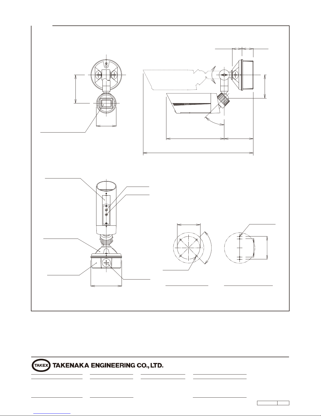
EXTERNAL DIMENSIONS
(36mm)
180°
1.42"
1.61"
(41mm)
(83.5mm)
(83.5mm)
3.29"
(66.7mm)
2.63"
4.06"
(103mm)
(85mm)
3.35"
(402mm)
4.17"
(106mm)
8.31"
(211mm)
15.83"MAX
45°
MountingBase
built-in
()
MemoryLED(yellow)
OperationLED(red)
Variable
Solid
angle
WiringHole
MountingBox
Ajustmentbox
Daylight
Delaytime
Detectionwindow
MountingBase
MountingBox
4-φ0.24"
(φ6mm)
4-φ0.16"
(φ4mm)
φ2.83"
(φ72mm)
φ3.29"
90°
φ4.41"
(φ112mm)
 Loading...