

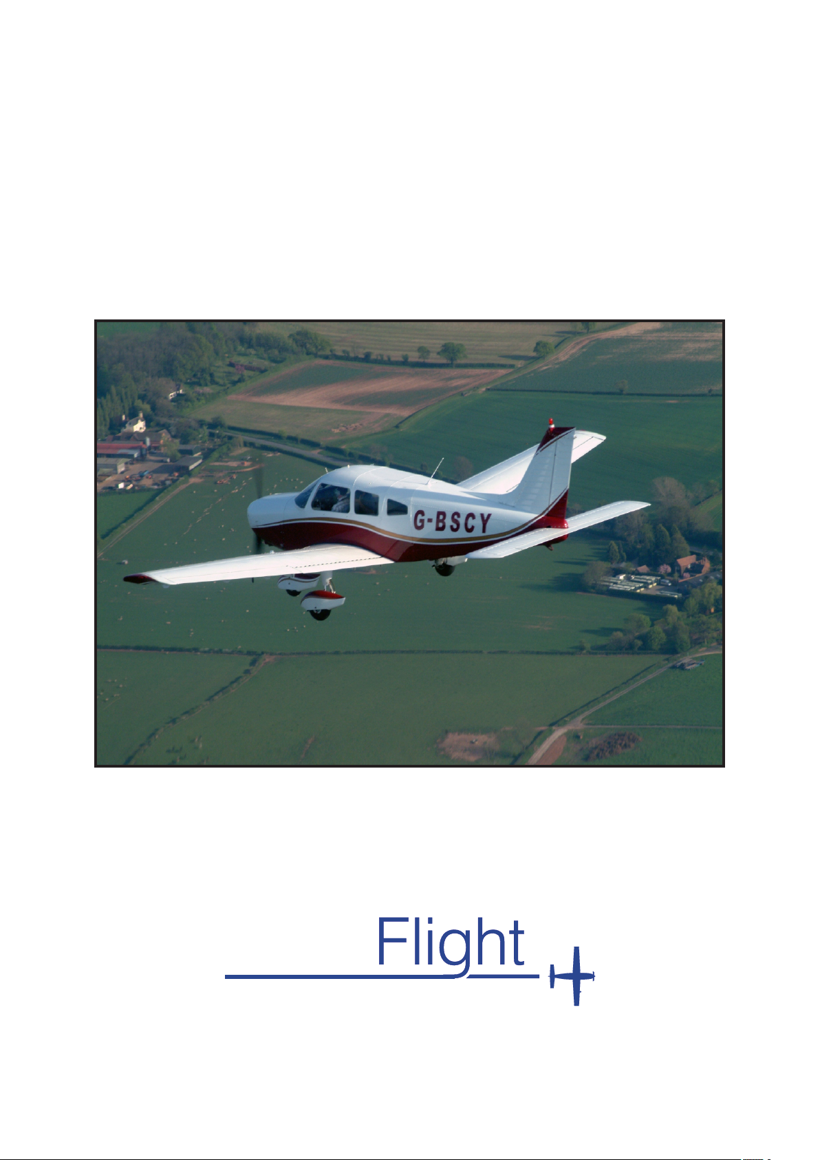
G-BSCY
Pilot’s Operating Handbook
Take
A V I A T I O N . c o m

Disclaimer
This pdf scan of the Pilots Operating
Handbook (POH) is for information,
and to aid flight planning only.
It should not replace reference to the
original documents, due to possible
updates since publication.
These are available for inspection at
Take Flight Aviation Limited on
request.
Take
A V I A T I O N . c o m
A0
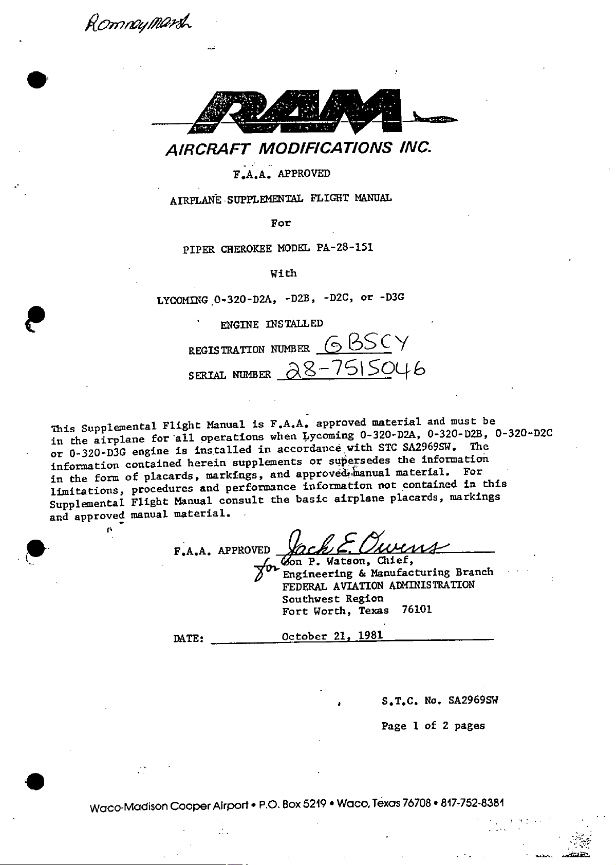
LYCOMING0-320-D2A,
PENGINE
Supplemental
This
airplane
the
in
0-320-D3G
or
information
form
the
in
limitations,
Supplemental
approved
and
for
engine
contained
placards,
of
procedures
Flight
manual
AIRCRAFT
F.A.A.
AIRPLANE
PIPER
REGISTRATION
SEIA
Flight
all
installed
is
herein
Manual
material.
SUPPLEMENTAL
CHEROKEE
NUMER761
Manual
operations
supplements
markings,
performance
and
consult
MODIFICATIONS
APPROVED
-D2C,
G3
MANUAL
or
fSS
FLIGHT
For
MODEL
With
INSTALLED
PA-28-151
-D2B,
NUMBER
So0
is
in
F.A.A.
when
and
the
approved
Lycoming
accordance
supersedes
or
approved4tnanual
information
basic
airplane
material
0-320-D2A,
with
INC.
-D3G
Y
C
SA2969SW.
STC
the
material.
contained
not
placards,
must
and
0-320-D2B,
information
For
in
markings
be
0-320-D2C
The
this
Waco-Madison
F.A.A.
DATE:
Cooper
AP
Airport
R
P.O.
*
#4VED~f~
on
Engineering
FEDERAL
Southwest
Fort
October
Box
Watson,
P.
Worth,
*
5219
Manufacturing
&
AVIATION
Region
Texas
1981
21,
Waco,
Texas
Chief,
Branch
ADMINISTRATION
76101
SA2969SW
S.T.C.
Page
No.
of
1
76708
pages
2
*
817-752-8381
AIRCRAFT
MODIFICATIONS
INC.
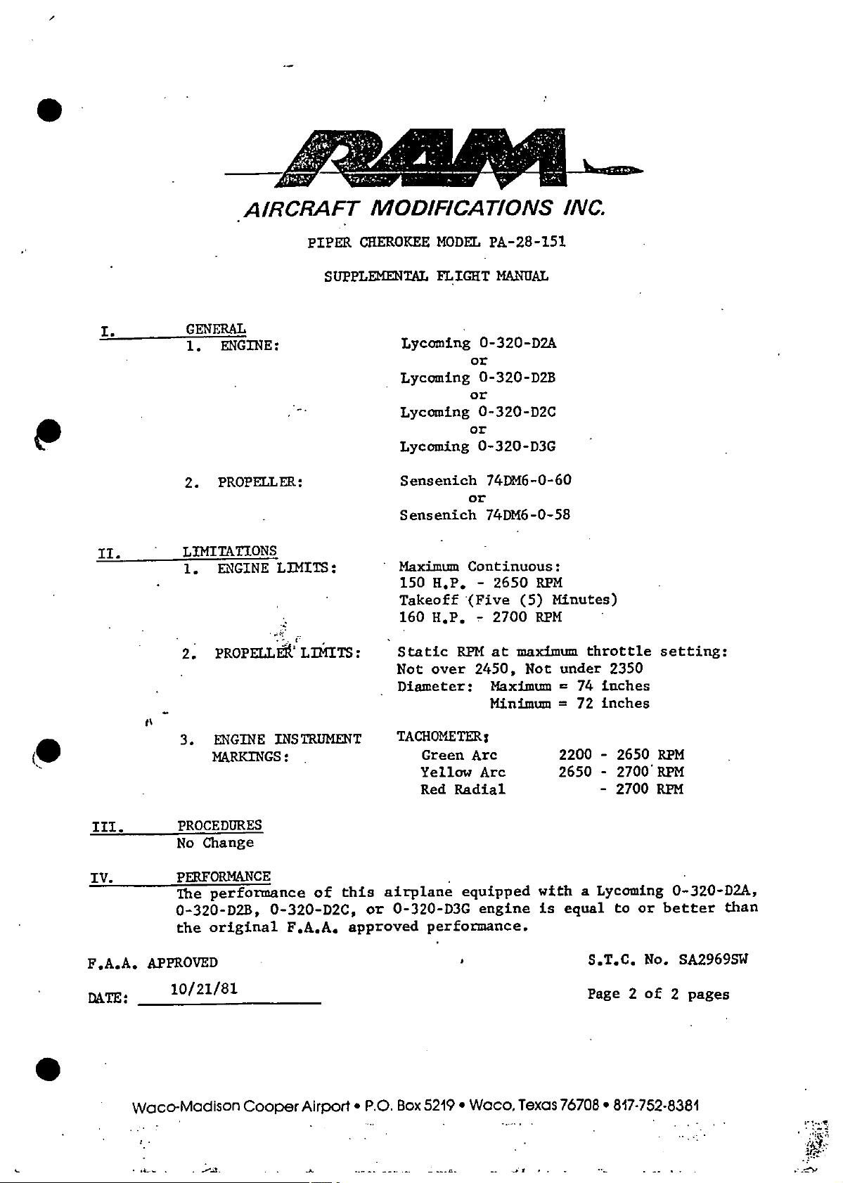
I.
II.
GENERAL
ENGINE:
1.
PROPELLER:
2.
LIMITATIONS
ENGINE
1.
PIPER
SUPPLEMENTAL
/-"
LIMITS:
CHEROKEE
Lycoming
Lycoming
Lycoming
Lycoming
Sensenich
Sensenich
Maximum
H.P.
150
Takeoff
160
H.P. -2700 RPM
MODEL
FLIGHT
0-320-D2A
or
0-320-D2B
or
0-320-D2C
or
O-320-D3G
or
Continuous:
-
(Five
PA-28-151
MANUAL
74DM6-0-60
74DM6-0-58
RPM
2650
Minutes)
(5)
(0
III.
IV.
F.A.A.
DATE:
PROPELLE
2.
I'
ENGINE
3.
MARKINGS:
PROCEDURES
Change
No
PERFORMANCE
performance
The
0-320-D2B,
original
the
APPROVED
10/21/81
LIMITS:
INSTRUMENT
this
of
0-320-D2C,
F.A.A.
approved
Static
Not
Diameter:
TACHOMETER:
Green
Yellow
Red
airplane
0-320-D3G
or
maximum
at
RPM
over
performance.
2450,
Arc
Arc
Radial
equipped
engine
Not
Maximum
Minimum
under
=
=
2200
2650
with
is
throttle
74
72
a
equal
S.T.C.
Page
2350
inches
inches
2650
-
-
2700'RPM
-
2700
Lycoming
or
to
No.
of
2
setting:
RPM
RPM
0-320-D2A,
better
SA2969SW
pages
2
than
Waco-Madison
Cooper
Airport
-
P.O.
Box
5219
*
Waco,
Texas
76708
817-752-8381
*
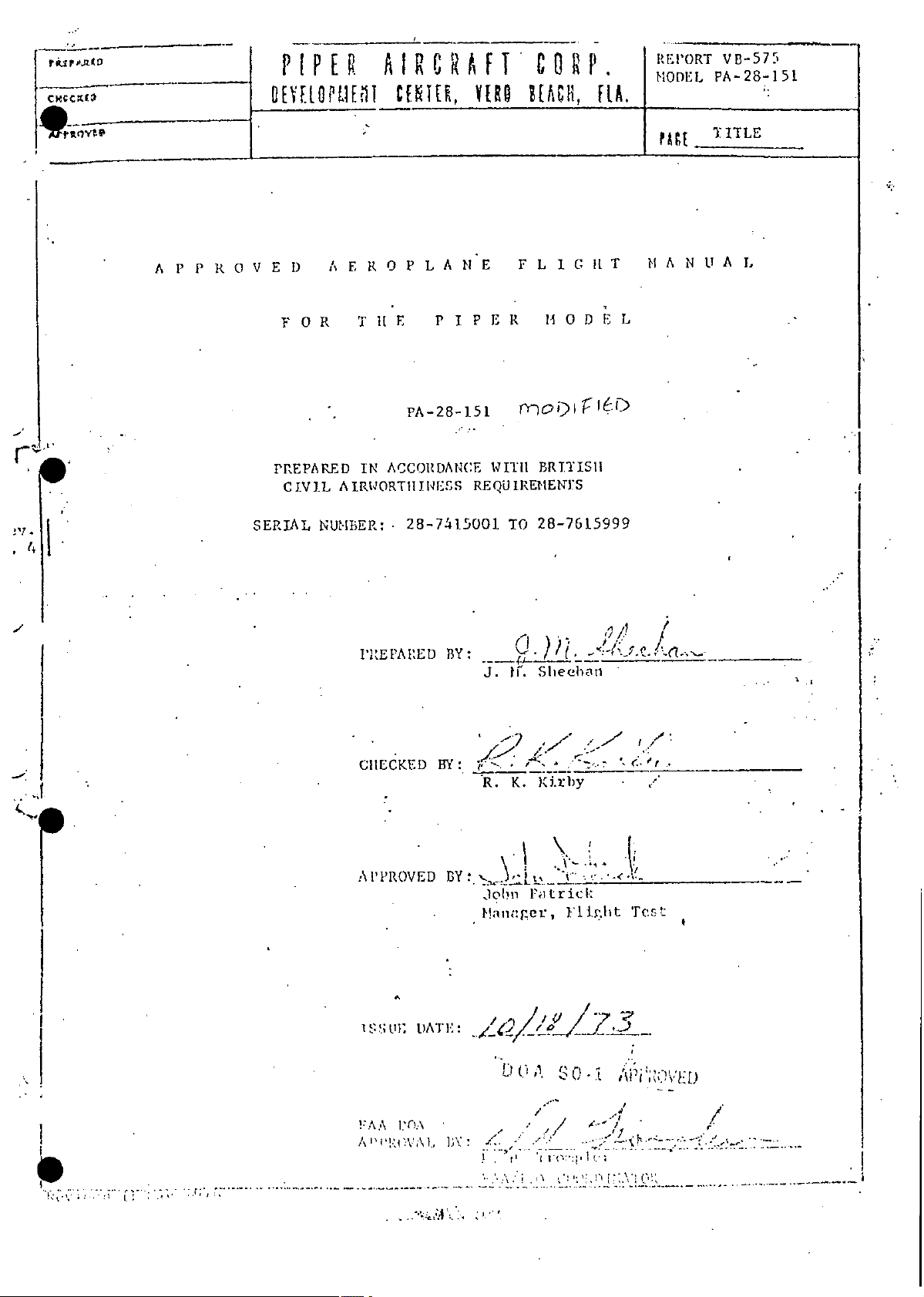
P
IPER
P_ I
A
OEYIOPLII
IR
UNI1T,
AFI
VERO
C
H[ACH,
P
RtA.
REPORT
MODEL
____________
AGE
vB-575
PA-28-151
TITLE
A
NUA
ROV
P
P
E
FOR
PREPARED
CIVIL
SERIAL
TItE
ACCORDANCE
IN
AIRWORTHINESS
NUMBER:
I
P
PA-28-151
28-7415001
BY:
AEROPLANE
D
FLIGtT
ER
P
WITH
REQUIRENENYS
MODEL
tO-
BRITISH
28-7615999
TO
SheehanBY*
Iff$D
MA
L
"
I
. . . ..
.
(__
Test
"~i
,,L[
/
. .. . ...
. . .
. . .
.
DATE"::
,:,..
l'n
l.'f.\
BY:
:
BY
l ; :
K.
R.
>Lt-
John
Manager,
/
"
U
...
. .
Kirby
-'
Fmat
/
"
"
rict:
Flight
/ 0
-
CHECKED
APPROVED
ST
IS
AA
P
1,,:
7
,

PIPER
§EYE.IPUENT
th
is
°'his
te
nific
C
AIRCRAFT
CENTER,
is
tho Flighi
This
ca
Conifc
o
YER0
Manual
hinss
Airwo
CORP
BEACH,
partoliho
forms
which
.............
aircaf
for
SAMODEL
RtA.
REPORT
_____
3- .
U
'........
..
CSL
....
VB-575
PA-28-151
-0
r7'I
/
a
2
SECTION
I.
GENERAL
Registration
A.
i.
2.
3.
4.
5.
6.
Particulars
Airplane
designation:
Registration
Constructor's
Designed
F.A.A.
Number:
Date
Model
Corporation
and
Certificate
Issue:
of
PA-28-151
Marks:
Serial
Constructed
of
British
Report
VB-575,
by:
Model
GY
C3
.'g-76
Piper
Vero
PIPER
&
Number:
32960
Airworthiness
Flight
Approved
PA-28l151
Aircraft
Beach,
for
Manual,
by
506.
Florida,
Export:
Piper
Secretary,
the
Corporation
U.S.A.
Aircraft
CiVil
This
7.
limitations
in
Aviation
airplane
Supplements
the
Authority
shall
Section
in
on:
operated
be
and
II
contained
in
any
Section
in
accordance
additional
VI.
with
limitations
the
X"
PIPER
BEY[OP
IRT
AIRCRAFT
CENTER,
YERO
CORP.
BEACH,
FLA.
REPORT
MODEL
FAtE
PA-28-151
2
VB-575
SECTION
SECTION
A.
B.
C.
D.
E.
F.
SECTION
A.
B.
1.
I.
Registration
Table
Amendment
General
Determination
Definitions
II.
Maximum
Baggage
GENERAL
Table
B.
GENERAL
Contents
of
System...................................................6
Arrangement
.................
LIMITATIONS
Weight
Loading
(continued)
Contents
of
particulars
..................................................
Temperature
of
Limitations
...................................................
...........................................
Drawing
.......................................
...............
i.S.A
Relation
in
...................................
.......................................
to
PAGE
I
2
9
10
14
14
C..
D.
E.
F.
G.
SECTION
A.
B.
C.
D.
E.
F.
Fuel
Centre
System
.........
ire
Plant
Power
Airspeed
Miscellaneous
111.
Introduction
Engine
Engine
Engine
Power-off
F
....................................................
Gravity
of
Limitations
Limitations
EMERGENCY
During
Fire
Power
Power
Landing
........................
...........
...........................
Limitations........................................
PROCEDURES
.................................................
Start
During
Loss
Loss
In
......
..................................................
.........................................
Take-off
Flight
...
.......................................
.
..............................
.........
................................
.................................
......
.1
21
2"
28
28
30
.31
3Z

I
SECTION
~~L,
PIPER
"YELEOP
S
of
GENERAL
Oil
of
Fuel
Oil
Roughness
..
Door
.
Lo
G.
Loss
It.
High
1.
Alternator
J.
Engine
K.
Spins
. .... .. ... 37
Open
M.
Eo
(continued)
Pressure
Pressure
Temperature
Failure
................................................
.
.
.
.
............
AIRCRAFT
YEIRO
R,
UIT
.............................................
CE
............................................
............................................
...................................
.
.
.
.
.
.
.
....
...................................
CORP.
BEACH,
.
R
A.
REPORT
MODEL
F
AtE
VB-575
rA-28-151
3
........
PAGE
34
35
35
36
37
SECTION
B.
C.
D.
E
F.
H.
I.
j.
K.
L..
M.
IV.
Preflight
•A.
Walk-around
Before
Starting.Engine
Starting
Starting
General
a.
Taxi
Before
Normal
Crosswind
Takeoff
Normal
NORMAL
.........................
Starting
Engine
Engine
Information
Takeoff.
Take-off
Component...............................................
Climb..................................................
Climb
PROCEDURES
..............................
Inspection
Engine
When
When
When
...............
(Flaps
....................................................
..........................
..........
Cold
Flooded
for
.................................................
......................................
..................................
Hot
................................
Starting
........................................
up).......................................
.............................
Engine
.....................
..............
.....
..
39
39
42
43
44
44
45
45
48
48
48
N.
0.
p
Normal
Approach
Post
Cruise...................................................48
Landing
Lndin
and
.......................................................
...........................................
49
51

*MODEL
"n---0
PIPER
11EL~OPUEIRT
AIRCRAFT
BEIER,.
CORP.
VERO
BEACH,
FLA.
REPORT
PACE
VB-575
PA-28-151
,
4
SECTION
Q.
R.
ION
SECT
A.
B.
C.
D.
E.
F.
G.
I.
Engine
Rough
V.
General
Maximum
Altitude
Take-off
Take-off
Net
En
Landing
GENERAL
Shut-down
Air
Take-off
Route
(continued)
...................................
Flight
PERFORMANCE
.............
Take-off
and
Procedures
Field
Performance
Procedures
............
and
Temperature
Lengths
Flight
.............
,
..................................
...........
...........................
LAnding
and
.
Path
...............................................
Speeds
and
Weight
.......
Speeds
........................................
...........................................
...................................
.....................................
for
................................
.
PAGE
51
51
.
60
52
58
61
67
70
73
H.
I.
SECTION
Explanation
Record
Landing
Glide
Net
VI.
Supplements
of
Field
SUPPLEMENTS
of
Lengths
Range
the
..
Supplemen
.....................
...
..............................................
................................
...................................
.......
System
....
...................
74
77
79
80

SECTION
OF
LIST
Figure
Figure
Figure
Figure
Figure
Figure
Figure
I-
ILLUSTRATIONS
GENERAL
General
1.
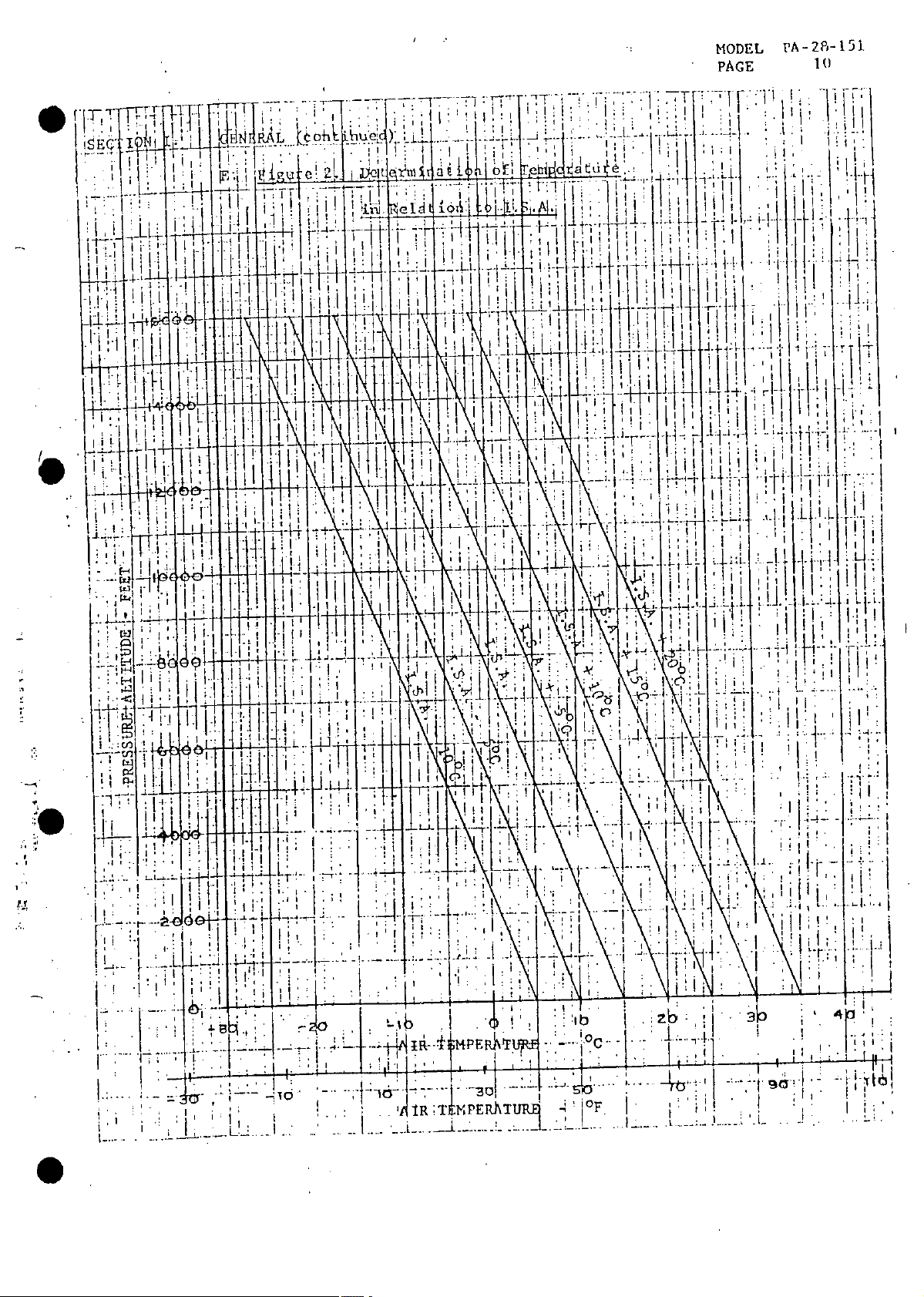
Determination
2.
Centre
3.
Conversion
4.
Pitot
5.
6.
Position
Position
7.
PIPER
.
DEYEtPUEPI
continued
(
Arrangement
Gravity
of
of
Location
Head
Error
Error
AIRCRAFT
CEUTE!,
Temperature
of
Envelope
Wind
Correction
Correction
CORP.
YEl
Drawing
Velocities
...........................
to
to
BEACH,
................................
relation
in
..............................
.
............
Obtain
Obtain
FIA.
to
E.A.S.
E.A.S.
REPORT
MODET.
........
I.S.A
...............
.........
;
(MP)
(Knots)
VB-575
PA-28-151
........
......
PAGE
9
Lo
16
53
54
55
56
Figure
Figure
Figure
Figure
Figure
"
Figure
Figure
8.
9.
10.
II°:
12.
13.
14.
Maximum
Altitude
Take-off
Take-off
Take-off
Net
Route
En
Landing
Glide
Net.
Take-off
and
Run
Distance
Perfor'mance
Distance
Range
and
Temperature
Required
Flight
............................................
Landing
....................................
Required
Path
Ceiling.
R~quired
Weight
................................
.
................................
...........
and
.......
for
.....................
of
Cross
Rate
..........................
Climb
....
59
63
66
69
.72
76
78

PIPER
EYELOPMET
AIRCRAFT
CENTER,
VEtO
CORP575
LA.
PEACH,
f
PtE
6
SECTION
I.
GENERAL,
Amendment
C.
the
are
with
revision
page.
issue
approved
zation
in
(continued)
System
current
The
amendment
indicated
revision
the.
date
revision
This
all
and
information
Amendments
other
manual
this
amendment
record
vertical
a
by
number.
given
are
previous
supplements
to
Piper.
than
without
state
sheet
number
pertinent
(Page
line
The
the
in
supersedes
revisions
Aircraft
consent
the
I
this
of
7).
the
in
revision
margin
and
the
to
published
Corporation,
of
manual
Amendmentsto
tiargin
number
the
of
the
contains
airplahe.
by
Piper
is
together
and
revised
original
the
another
and
Aircraft
I
noted
the
the
latest
ogani-
included
Cor-
on
text
organization.
that
Page
for
of
on
be
of
80
and
Page
reflected
Section
their
80
embodiment
Section
of
on
VI.
VI.
poration,
These
amendment
-
the
-A
into
are
amendments
record
the
of
manual
will
record
approved
provided
is
necessarily
not
sheet
of
supplements
responsibility
the

-
-
----
-1
[
PER
AIRCRAFT
G
E
M,
REPORTVB-575
MODEL
PA-228-151
'N
REVISION
NO.
2
125
110.
.O
CAJ
10
.A
OF
3
Q
DATE
REVISION.
DAY
L5
1A
REVISED
YR.
74
A:Redrawn
*1
74
fl-
(CAA)
140
5
..
7
[
STATES
YR
4
...
7/
UNIED
AMENDmENT
APPROVAL
BY
R.F.
"
R.K.
AFPROV
DATE
DAY
/
.....
-
-
'
........
1)D
F.A.A.
RECORD
Deleted
Aerobatic
cQaalified
Deleted
Changed
Speed
........
Deleted
batic
SHEET
REVISION
Reference
Propeller
Example
at
...................
Reference
Manoeuvres
Specified
Corrected
Charts
TITLE
Manoeuvres
Battery
Light
Battery
T.O.
to
Capacity
Check
Climb
&
Weight
......
.
Aero-
to
Capacity
Distance
PAGES
AFFECTED
&
22
36
45
70
72
a
20
36
63,
61,
23
5
66
64
'
.
3
4
j/
'A
1
1
8
-
-'A
75
I
-
'-0
6
L.11;
P
AP"
M5
p
21,
20,
'
tc
19,
49
26,
Title
&
7
Add
speed
,-75
I
T
-
effectivity.
"
Revised
Serial
serial
and
Applicability
28-7615999
No.
.
ti
wing-flops
new
extended
number
up
I
I

c,.,l
PIPER
DEYELO
ENT
AIRCRAFT
CETE,
VE1O
CORP.
BEACH,
FA.
REPORTVB-575
MODEL
PA-28-151
REVISION
NO.
DATE
REVISION
AY
MO.
OF
JYR.
REVISED
BY
C.A.A.
APPROVAL
DATE
DAY
AMENDMENT
(CAA)
MO.
YR.
RECORD
REVISION
SHEET
TITLE
PACE
8
PAGES
AFFECTED.
~/

C
IR
IER
I________
R
,EYELOPUEIT
A
CERTER,
RAFTI
VERO
CO0R
BEACH,
P
FLA.
REPORT
VB-575
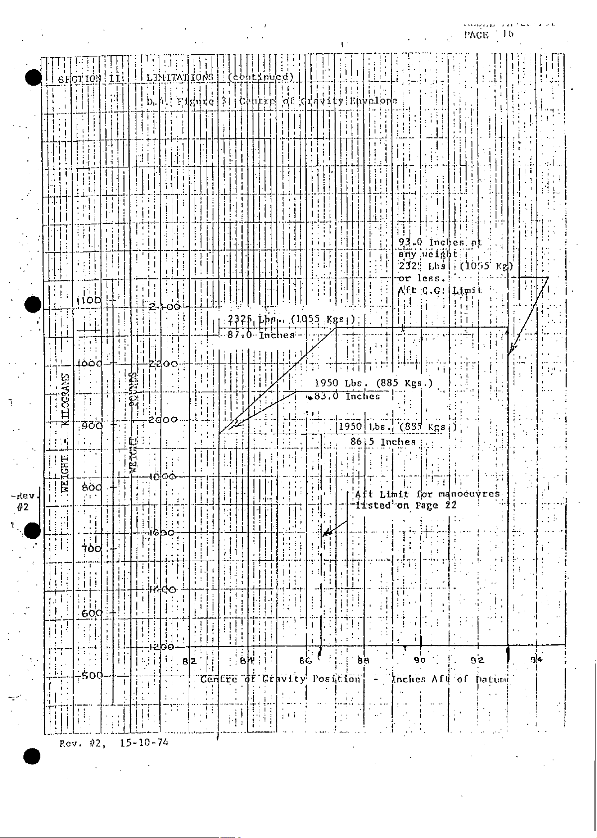
SECTION
vp
I.
FIGURE
GENERAL,
General
D.
1.
(continued)
Arrangement
Drawing
(not
to
scale)
rM"
5'
_J:P3
3"
9.6"
''-
GIOVID
0
IC0
I
151
n
MODEL
PAGE
-
-
iso'
....
-
,*7-
1
7F:9'''
-
I-
-
J
:IL
-"
PA-28-
I
f 1
I ' I
1 1 ; l i I
0j*
:..
;4
,F]
i~i-!!
I
T
j
I.
°
T-
,ih
I
7i
tit,
i
;
.
.
II
-
L
_a.
.
A
-.
I
_'
-
~~~
~
...
J-TUR
~
I
M-"
ER
; :j
i
:1
":
.
i.:.,
i
PIPER
[LtOPtE
E
AIRCRAFT
T
CE
lER,
VERO
RP
CO
BEACH,
FLA.
REPORTVB-575
SECTION
I.
GENERAL,
Definitions
F.
1.
2.
(continued)
TEAPERATURE
AIR
temperature
The
fluenced
reported,
a
Navigation
derived
ALTITUDE
The
which
terms
by
in
altitude
is
of
of
aeroplane.
the
forecast
Regulations,
accordance
shown
expression
the
altitude
above
the
on
free
or,
with
the
air
This
when
a
of
mean
permitted
declared
approved
an
charts
atmospheric
sea
but
near
to,
temperature
by
temperature
system,
pressure
is
pressure
level
according
not
may
Air
the
altitude
in
In-
be
to
the
inter-relation
Standard
setting
altimeter
millimeters
I.S.A.
3.
International
temperature
GRADIENT
4.
tangent
The
tage
i.e.,
of
Atmosphere
sub-scale
the
1,013
at
mercury).
of
Standard
variation
CLIIB
OF
the
of
these
millibars
change
horizontal
factors
(I.S.A.).
an
of
Atmosphere.
versus
angle
of
in
in
This
accurate
(29.92
altitude.
climb
height
distance
expressed
International
the
be
May
pressure
inches
Page
See
traveled
obtained
type
760
or
for
10
percen-
a
as
100
x
by

PIPER
AIRCRAFT
CO
RP.
REPORT
VB-575
SECTION
1.
EJ,,,E
GENERAL,
GROSS
5.
The
expected
be
tained
niques
NET
6.
The
in
(continued)
PERFORUANCE
average
PERFORMANCE
gross
the
performance
to
flown
and
described
performance
relevant
which
achieve
in
in
requirement
or
accordance
manual.
the
modified
a
exceed
with
in
make
to
A
aeroplanes
fleet
of
satisfactorily
if
associated
the
manner
the
appropriate
MODEL
prescribed
allowance
PA-28-151
can
main-
tech-
7.
8.
9.
10.
those
for
dealt
not
RUNWAY
HARD
surface
A
HEIGHT
lowest
The
plane
WEIGHT
The
equipment,
A.S.I.R.
and
total
variations
Operational
with
in
concrete
as
such
of
and
between
the
payload.
distance
the'relevant
weight
crew
the
from
or
datum.
aeroplane,
Gross
Regulations.
tarmac.
the
Performance
lowest
including
part
the
of
fuel,
which
aero-
oil,
are
uncorrected
The
Air
Speed
Indicator
Reading.
AIRCRAFT
CORP
RPPIPER
VB-575
c~a
ODEVELOPMENT
SECTION
I.
uf~rAti[
I
GENERAL,
ETE1DPEB1
(continued)
12.
13.
I.A.S.
Indicated
The
instrument
for
E.A.S.
The.Equivalent
position
for
T.A.S.
True
The
undisturbed
IL.
RTU
CETER,
Air
?E
Y[R0
Speed,
Air
error
Air
compressibility
and
Speed
which
air,
eEAR,
DFAC_,
only.
Speed,
the
of
is
IA.
RLA.
which
is
which
aeroplance
the
is
E.A.S.
MODEL
A.SI.R.
the
I.A.S.
errors.
relative
corrected
PA-28-151
133
corrected
correjted
the
to
for
14.
15.
16.
temperature.
altitude
TAKE-OFF
The
complete
configuration,
glide
a
MANOEUVRING
The
flight
V___O
The
and
SAFETY
minimum
failure
di
maximum
controls.
Normal
speed
a
SPEED
speed
Operating
SPEED
at
of
adequate
margin
safe
for
which,
engine
the
control
full
Limit
following
in
exists
above
the
application
Speed
sudden
the
stall.
which
take-off
establish
to
primary
of
the
is
and.
maximum
cruising
speed.

AA[IfCO
.
RL'LOWIVB-575
_
__
FACE
SECTION
II.
LIMITAT
INSTRUCTIONS
A.
B.
IONS
AEROPLANE
TIE
following
The
1.
2.
3.
4.
Baggage
maximum
The
operation,
The
The
The
is
The
weight
TIlIS
IN
eximum
Maximum
11aximum
pounds..
1950
aeroplane
limit.
LoadiI&
baggage
baggage
MUST
SECTION
weights
Take-off
Landing
Weight
*
OPERATED
BE
given
not
is
capacity
and
SO
OBSERVED.
ARE
maximum
are
Weight
Weight
manoeuvres
the
for
structurally
is
passengers
aft
is
is
200
TMAT
2325
2325
pounds.
TiIl
liitaotious.
potinds.
pounds.
limited
not
are
LIMITATIt)NS
listed
on
a
by
acrohat
For
allowed.
ANI1
l'ag
zero
In
Id
27
I
Fuel
C.
I.
2.
3.
Items
strument
System
There
recommended
better'rol-.
word
The
1.0
(1.0
colour
gal.lon
unusable
gallon
*
U.S.
The
as
marked
no
are
."gallob"
gallon
must
either
marked.
in
the
loading
the,
as
in
each
be
fuel
that
control.
unless
fuel
is
limitationS.
fuel
used
otherwise
total
load
throughout
aircraft
this
wing
per
placarded
in
symmetrical
be
stated.
critical
side).
the
or
this
has
However,
report
been
flight
applicable
it
provide
to
,.ans
determined
attitudes.
i&-
is
0
_
_!_
_
It
_____IER
C
IR
A
T
I'-C
UEY[1Pn1EFPI
L[l
RA
,
Y
F
G
CU9RCP
pull,
E
A
F A.
1
Rt".ORT
1
R'
v
iA-Th-
Il
SECTION
11.
LIIATIONS
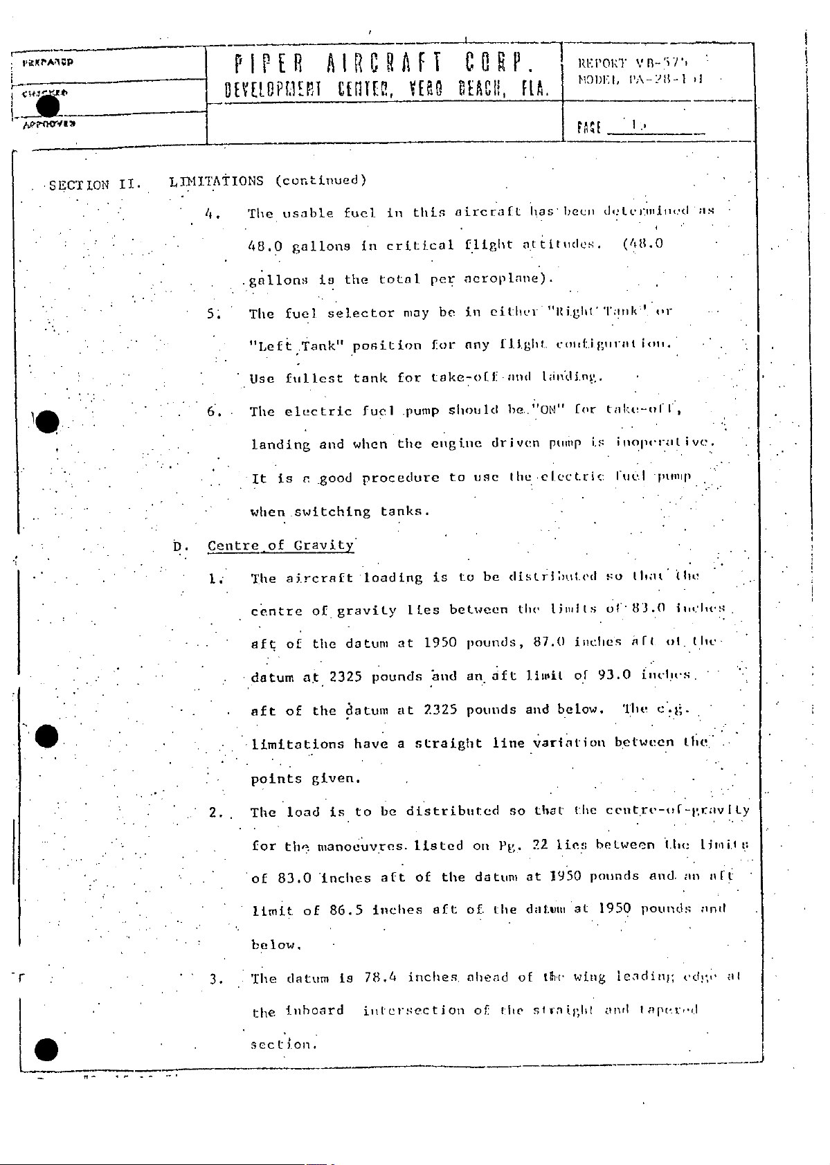
4.
5;
6.
Centre-of
D.
I
(continued)
The
48.0
gallons
The
"Left
Use
The
landing
is
It
when
The
usable
gallons
it
fuel
selector
Tank"
fullest
electric
and
good
a
switching
Gravity
aircraft
fuel
in
the
position
tank
fuel
when
procedure
loading
in
critical
total
may
for
the
tanks.
this
pump
aircraft
flight
aeroplane).
per
ie
be
any
for
take-off
should
engine
to
to
is
use
be
either
flight.
.and
be.''ON"
driven
the
listri
has
attitllde'.
"Right'':ilt'
coiiif.igiirat
inni
t;i]
pump
e[ectric
becl,
for
tl
ed
deltc-.lil.d
(481.0
tak(a-
i
li'otNI[
iS
u
I
so
ioit.
Ilioo
o'r
iI
It
pnilp
uit!"
is
vy.
I
ot.
fm-lt-s.
c'.
t.i{
knd,
pounds
Iapr.,I
i
tlic
[ie
an
ri
limit
a
.n?
,edg
l;
at
83.0
of'
lts
lh.
oft
line
Pg.
the
lite
the
1iisi1
and
so
at
d;nlnu,
of
iinches
87.0
of
below.
variation
the
that
ties
22
1950
at
wing
tiwr
igiht
siVl
AF.
93.0
The
betwecn
centre-of-jgravity
between
pounds
1950
leidin);
aie,1
1950
bnd
2325
straight
listed
of
aft
inches,
between
pounds,
an
pounds
on
datum
tile
of.
ahead
of
pounds
be
aft
inches
78.4
ties
at
at
a
distributed
gravity
of
a.t
of
load
th
83.0
of
datum
inboard
of
datum
the
2325
datum
the
have
given.
to
is
nanoeuvres.
inches
86.5
is
inlcrsection
centre
aft
datum
aft
.
1 ..limitations
2.
3.
points
The
for
of
limit
below.
'The
tile
*
•
r
sect.011
PAGL
r
I
i-f-
I
UTA
III52'
1111
I.I
.'.~~~A qLJL
I
. I
III
,
55
.(1
j!;rj
4 .1 1 Ji.lJ
I
1 1 ! j!
6
i e
ir
Lb;
g
*-16!
LJ
9.
'j1i'd
I
aiy4
'I9
~..
tI
KI'
.!,s
mit
Y g)
" I
,
#2
i'j ,,.i
'1
I
iii ii;R
Lt •z
1950
--.
2
J-
I
l.T1
....
..-
.-
..
..
.
...
... .
..
.
.
I,
--
Lbs.
,
. ..
o
86.5
-sted
T. .
se
(885
Inches,
-on
''
..
..
.
I
Kgs
Vage
i
"
gbI
I
:
. .
iu: 5-: 1
I'.1
.
"
22
I
!
..
..
-
"a u k
"
LVy.
'2,
1-
40-7
'
j
.
.I
.
.. .
.
.
I
..
.
,'
-
-
;-
'I
House
Airport
R
Dial~
: "
..
Site
Hill
3
Authority
Group
OYR.
H6
567171
0293
Fax:
,'
...
Biggin
573149
573999
0293
'
',:
Hill
'0293
'"
Flying\Services
507
N,-r4
.-
Airport
.
.
-
Aircraft
Standards
9/97/CtAw/171'"
February
t
2
Maintenance
Department
1990
"
"
Aviation
Civil
Regulatcon
Area
a
Safety
Aviation
South
Gatwick
'
(
Gatwick
Sussex
West
Switchboard
Tel:
Direct
Bamrah
S
878753
.
Falcon
T1
Telex:
A
(TR)
Hangar
Biggin
Kent
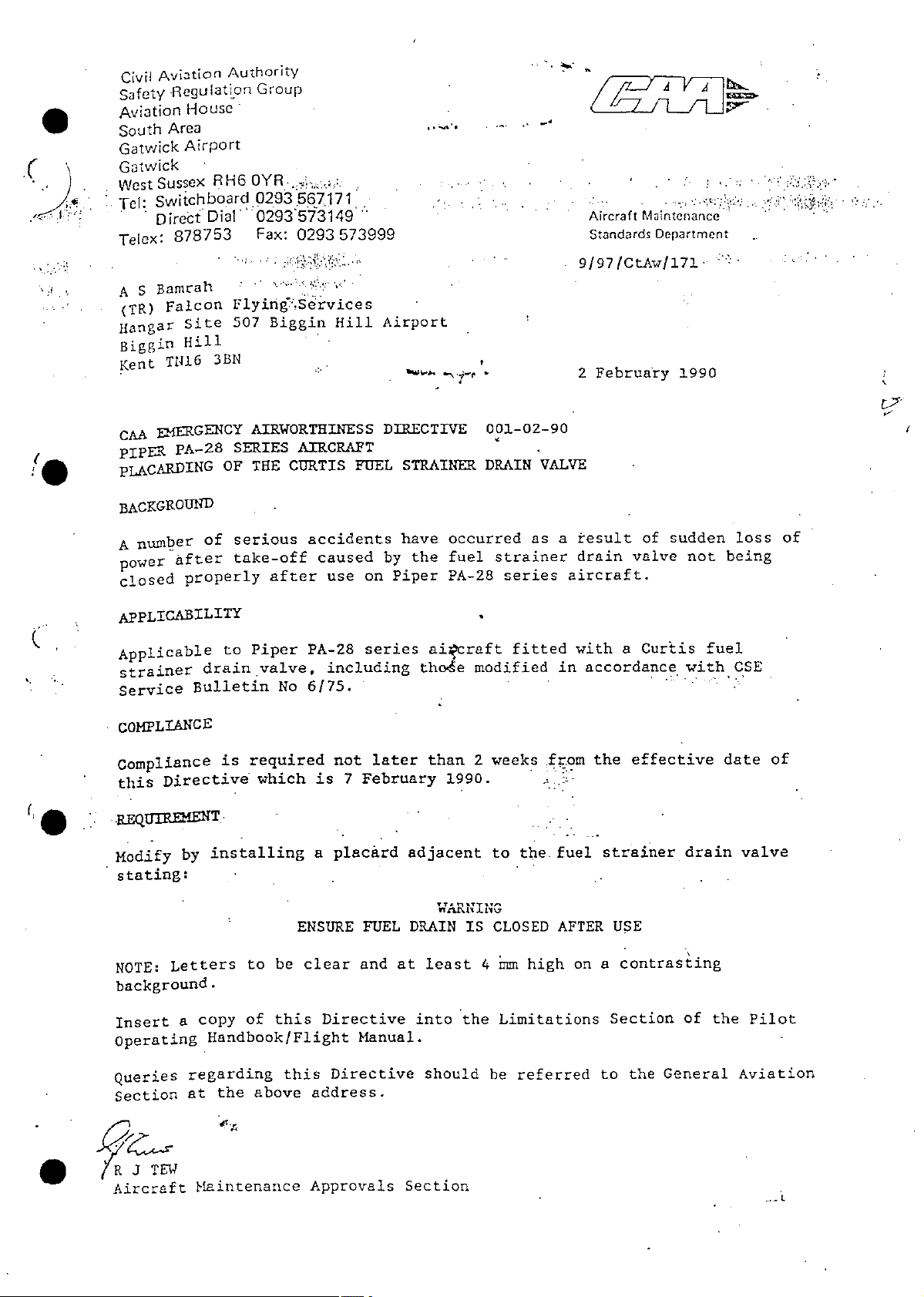
EMfERGENCY
CA.
PIPER
pLACARDING
BACKGROUND
A
power
closed
APPLICABILITY
Applicable
strainer
Service
COMPLIANCE
Compliance
this
Modify
stating:
PA-28
number
After
properly
Directive
by
of
drain
Bulletin
installing
AIRWORTHINESS
SERIES
OF
serious
take-off
to
required
is
CURTIS
THE
after
Piper
valve,
No
which
AIRCRAFT
accidents
PA-28
6/75.
FUEL
caused
on
use
series
including
later
not
February
7
is
placard
a
DIRECTIVE
STRAINER
have
by
Piper
occurred
fuel
the
PA-28
aircraft
thode
than
1990.
adjacent
001-02-90
DRAIN
modified
weeks
2
to
VALVE
as
strainer
series
fitted
the.
result
a
drain
aircraft.
with
accordance
in
the
from
fuel
sudden
of
valve
Curtis
a
effective
strainer
being
not
fuel
with
date
drain
loss
CSE
valve
of
of
on
USE
contrasting
a
Section
General
the
to
of
the
Aviation
Pilot
CLOSED
ENSURE
clear
be
to
this
of
Handbook/Flight
this
the
above
address.
Approvals
J
TEW
Letters
copy
a
regarding
at
Miaintenance
NOTE:
background.
Insert
Operating
Queries
Section
•
R
Aircraft
FUEL
and
Directive
Manual.
Directive
DRAIN
at
into
Section
IS
least
the
should
rm
4
Limitations
be
AFTER
high
referred

cmcnc
A,,,lOYUO
PIPER
DEY[LOPUENT
AIRCRAFT
CEATER,
VERO
BEACR,
CORP.
RtA.
REPORT
MODEL
PAlE
VB-575
PA-28-151
U
SECTION
*
*
II.
L1ITATIONS
Power-Plant
E.
ENGINE
Lycoming
PROPELLER
Sensenich
Diameter:
Pitch:
Static
(continued)
Limitations
O-320-E3D
DM6-O-58
74
Inches
74
Inches
72
Inches
58
maximum
at
RPM
over
Not
under
Not
with
2375
2275
carburetor
Maximum
Minimum
permissible
RPM
RPM
setting
throttle
10-5009
setting:
additional
No
McCauley
Diameter:
Pitch:
Static
No
FUEL
The
80/87
RPM
Not
Not
additional
minimum
octane
tolerance
IC160EGM7653
Inches
76
Inches
74.5
inches
53
maximum
at
2400
over
under'2300
tolerance
grade
of
aviation
permitted.
Maximum
Minimum
permissible
RPM
RPM
permitted.
approved
fuel
gasoline,
use
setting:
in
throttle
for
specification
this
No.
engine
D.
is
R.D.
Eng.
Gallon.
2/485
with
a
maximum
limit
of
5.5
MLS.
TEL/Imperial

PIPER
DEYELOPMERT
AIRCRAFT
CEUTER,
YES
CORP.
GEAC,
FLA.
REPOR
MODEL
VB-575
PA-28-151
SECTION
II.
LIMITATIONS
OIL
oil
The
Eng.
D
No.
Specification.
TEMPERATURE
OIL
Normal
Maximum
PRESSURE
OIL
minimum
A
ceeded
(continued)
approved
2472
Operating
pressure
oil
within
30
use
for
grade
Range
seconds
B/O
of
in
and
25
when
engine
this
the
75°F
PSI
starting
latest
to
should
specification
to
is
applicable
245°F
245°F
be
the
(Green
(Red
obtained
engine.
Lycoming
Arc)
Line)
ex-
or
*
*
Normal
Caution
Minimum
Maximum
FUEL
Normal
PRESSURE
Maximum
Minimum
ENGINE
maximum
The
flight
RPM
500
Operating
Range
Operating
SPEED
is
LIMITATIONS
permissible
2700
2700
to
RPM
Range
Range
(Red
RPM
rotational
Line).*
(Green
PSI
60
PSI
25
PSI'
.5
Arc).*
to
to
to
speed
The
PSI
90
PSI
60
25
90
PSI
8
PSI
8
PSI
.5
normal
PSI
PSI
for
(Green
.(Yellow,
(Red
(Red
(Green
(Red
(Red
conditions
all
operating
Arc)
Arc)
Line
Line)
Arc)
Line)
Line)
range
*
*
*
*
*
*
of
is
Items
colour
marked
marked.
*
must
either
be
plicardcd
or
the
applicable
Instrument

PIPER
DEYELIPiENT
AI
CEITER,
o
RCRAFT
Y1l1
COR
KEACK,
P
FLA.
REPORTV
ODEL
M
HH
PA-28-
19
B-575
151
SECTION
II.
LIMITATIONS
FUEL/AIR
The
accordance
F.
MIXTURE
operation
Airspeed
2.
3.
-
The
Indicated
NEVER
is
NORMAL
Is
flight,
1.
(continued)
CONTROL
limitations
and
with
the
Limitations
operating
EXCEED
MPH
185
OPERATING
MPH
145
the
latest
airspeeds
SPEED,
I.A.S.
-
aeroplane
applicable
-
speed
LIMIT
I.A.S.
fuel/air
the
of
Lycoming
limitations
(I.A.S.)
NE
V
Knots).
(160
SPEED,
Knots).
(126
should
VNO*
not
are
be
mixture
Specification.
given
During
flown
in
normal
at
shall
terms
cruising
speed
a
be
of
in
*
_
flown
aeroplane
VNO.
greater
-speeds
-tever
*.,due
~~ANOEUVRING
4.
'is
an
stabilator,
a.apeed
WINGFLAPS
5.
.
Is
be
than
Items
colour
marked
marked.
than
between
exceed
regard
MPH
127
approach
greater
MPH
130
extended
VFE.
must
*
speed
:to
SPEED*
I.A.S.
-
to
or
EXTENDED
I.A;S.
-
when
either
The
normal
the
at
prevailing
the
stall
the
ruxIder
than
the
be
operating
discretion
the
Knots).
(il1
or
control
manoeuvring
the
SPEED.
Knots).:The
(113
aeroplane
placarded
VFE*
shall
atmospheric
application
full
shall
(S/N.28-7415001
.S/N.28-7515449)
is
or
only
limit
of
Manoeuvres
not
speed.
wing
flying
applicable
the
be
speed
pilot,
the
conditions.
involving
of
undertaken
be
flaps
a
at
and
speed
at
the.
having
aileron,
at
thru
shall
greater
instrument
.
not,
.
:
Rev.
3,
1-8-75

COR
C
bEB,
II
AT
AILU
CI
FI
RA
1RT[2,
V[C9
P
I
PIIER
IPEIR
P
fl
'tone[ 20
?PU
P.
R
flA.
REPORT
MtODEL
PA-28-151
VB-575
.
SECTION
II.
LIMrTATIONS
WING-FIAPS
119
is
extended
VFE.
then
*
ENTRY
6.
127
Is
-Eights.and
AIRSPEED
7.
Green
-(Normal
Yellow
(continued)
EXTENDED
MPH-IAS
when
SPEED
MPH
Arc
FOR
-
Chandelles.
INDICATOR
Operating
Arc
(103
aeroplane
the
ANOEUVERS
I.A.S.
Range)
SPEED,
TS,.).
(111
COLOR
VFE*
Knots)
MARKINGS
(S/N
wing
The
flying
is
LISTED
65
for
MPH
28-7615001
flaps
PAGE
ON
steep
to
at
140
shall
speed
a
22
turns,
MPH
and
not
greater
Lazy
(E.A.S.)
up)
be
:(Caution
:White
.(Flaps
(Flaps
Radial
S(Never.Exceed
2. -
0
,
Range-Smooth
Arc
Extended
Extended
Line
Red
Range>
Range)
Spee-Smooth
"'"
Air)
140
58
(S/N
58
.(S/N
Air)
MPH
28-7415001
28-7515449)
S/N
MPH
28-7615001
'176
'"..
to
to
125
115
MP
MPH
thru
MPH
and
(E.A.S.)
(E.A.S.)
(E.A.S.)
up)
."
.
.
"
:
'
'i
,
(E.A.S.)
MPH
176
to
MPH
Items
.colour
marked
marked.
*
either
must
be
placarded
or
the
applicable
instrument
Af
R
I
R
I
A
P
IRR
PIER
DEVEtLOPUENTI€
E,
U8
IEOOg[
C
I
HCHR.
PREPORT
0R
,HA
MODEL
____________
PA[
VB-575
PA-28-151
21
SECTION
1.
2.
3.
4.
I
1
5
II.
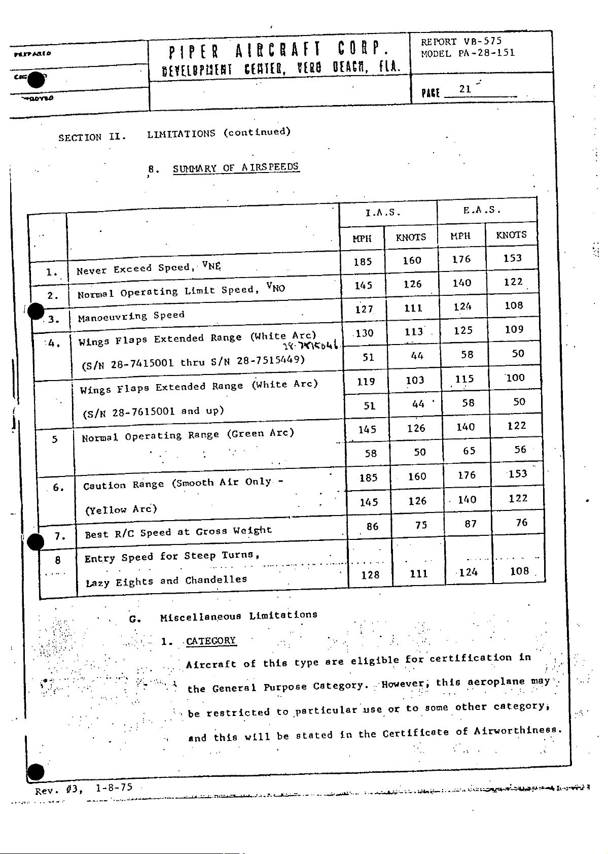
Never
Normal
Manoeuvring
Wings
(SIN
Wings
(S/N
Normal
Exceed
operating
Flaps
28-7415001
Flaps
28-7615001
operating
LIMITATIONS
SU11NARY
8.
Speed,
Speed
Extended
Extended
VNE
Limit
thru
and
Range
up)
(continued)
AIRSPEEDS
OF
Speed,
Range
28-7515449)
S/N
Range
(Green
VNO
(White
(White
Arc)
Arc)
Arc)
,
I.A.S.
MPH
185
145
127
10
51
119
51
145
58
KNOTS
160
126
ill
113
44
103
44
126
50
E.A
MPH
176
140
124
125
58
115
58
140
65
.S.
KNOTS
153
122
108
109
50
100
50
122
56
...
6.
7.
8
Caution
(Yellow
R/C
Best
Entry
Lazy
Speed
Eights
Range
Arc)
Speed
G.
(Smooth
at
Steep
for
Chandelles
and
Miscellaneous
CATEGORY
1.
Aircraft
the
be
and
Air
Gross
Weight
Turns,
General
restricted
this
Only•-
Limit
this
of
Purpose
will
tiOns
type
Category.
particular
to
stated
be
are
185
145
86
128
eligible
use
the
in
160
126
75
ill
certification
for
to
this
some
However,
or
Certificate
176
140
87
124
aeroplane
other
Airworthiness.
of
.153
122
108
category.
76
in
may'
Rev.
03,
1-8-75
"
'
'--'

*
jcmcnUv
PIPER
RT
EM
Et
AIRCRAFT
CENTER,
VERO
CORP.
DERO,
REPORT
[FLA.'
MODEL
V13-575
PA-28-151
SECTION
II.
LIMITATIONS
VFR
2.
Flying
the
the
3.
4.
FLIGHT
Night
FLIGHT
When
(continued)
IFR
and
VFR
required
Navigation
Air
BY
flying
installed,
Regulations.
AT
flying
FLIGHT
and
equipment
NIGHT
is
and
HIGH
above
during
IFR
Regulations.
permitted
allowed
when
ALTITUDE
10,000
day
installed
is
when
feet,
by
or
the.
the
it
night
and
required
Air
is
PACE
is
when
Navigation
pilot's
the
22
permitted
allowed
equipment
when
by
is
".6;
5.
responsibility
pilot
the
compliance
FLIGHT
aeroplane
The
condit
APPROVED
The
(a)
weight
and
with
ICING
IN
ions.
FLIGHT
following
provided
Steep
(1)
Lazy
(2)
Chandelles
(3)
consider
to
passengers,
all
CONDITIONS
not
is
MANOEUVRES*
manoeuvtes,
aeroplane
the
center
and
Turns
Eights
the
oxygen
applicable
approved
is
gravity
of
phy'sical'limitations
equipment
Air
flight
for
permitted
are
loaded
limits.
Navigation
within
required,
Regulations.
icing
in
the
of
and
approved
p.T"
placarded
must
Items
inst
.76
marked
rument
*
colour
either
marked.
be
or
applicable
the

qcuo
nynna
PIPER
gEY[LOPElT
AIRCRAFT
CIWT,
Y118
CORP.
BEACH,
FLA.
REPORTVB-575
MODEL
PACE
lA-28-151
________
SECTION
II.
LRIITATIONS
(b)
(c)
()
7.
FLIGHT
The
a
2.0 g with
manoeuvring
nent
(continued)
and
Baggage
manoeuvres
All
approved
Item
6
are
Aerobatic
LOAD
FACTORS
PA-28-151 structure
positive
deformation
manoeuvring
the flaps
load
aft
listed
flight
prohibited
manoeuvres
factor
up
pass~ngers
on
Page
manoeuvres
above a gross
are
has
been
load
factor
fully
to
deflected
of
1.76 g flaps
a
gross
are
22,
not
permitted.
designed
of
weight
prohibited
Item
6.
listed
(400)
on
weight
to
4.4 g flaps
and
up
without
of
1950
for
all
page
withstand
pounds.
22,
of
1950
up,
a negative
perma-
lIbs.
Items
The
positive
2.0 g with
peranentikeformation
8;
MINIMUM
The minimum
marked
PA-28-151.
manoeuvring
the
CREW
crew
*
must
either
structure
load
flaps'
is
be
fully
up
one
placarded
has
been
factor
deflected
to a gross
pilot.
or
designed
of 3.8 g flaps
weight
the
(40')
appticable
to
withstand
without
of
2325
up
a
and
pounds.
instrument
colour
marked.
 Loading...