

Takata Racing RACE 4 User Manual

INSTALLATION & OPERATING
INSTRUCTIONS
RACING Models
Edition: 08/2012
Part No: EA 12.2
T
HIS M A N UAL C O NTAI N S IMPO R T ANT
INFO R M ATION S HOW N A S
SAFETY INSTRUCTIONS contain important hints to help you to install, use
and maintain the TAKATA Racing Harness properly and effectively.
This harness belt, when properly installed and used according to
applicable instructions can minimize injury. The ability of any
restraint system to minimize or prevent injuries is directly related
to the type and severity of accident. No restraint system can
prevent injury or death in every accident.
Racing harness belts are NOT designed to be installed into street
legal vehicles, and DO NOT meet federal and state vehicle safety
regulations. They are designed and tested to be used exclusively in
race cars and only in on-track events.
“This article is sold without warranty, express or implied, including
but not limited to the implied warranties of merchantability and
fitness for a particular purpose, all of which are specifically
disclaimed, and no warranty or representation is made as to this
product’s capability to protect the user from any injury or death.
Racing is dangerous! The user assumes the risk.
WARNINGS deal with important issues about installation, use,
misuse or modification of the racing harness.
Ignoring these WARNINGS will significantly reduce the
performance of the racing harness system. This can result in
serious personal injury or death during an accident.
Always read carefully and follow the information in
this manual, especially those highlighted as above.
A
B O U T T H E I M P O R T A N C E
O F T H I S M A N U A L
TAKATA Racing has attempted to make this racing harness manual extensive
and comprehensive. We have created it to help the reader understand racing
harness installation, use and maintenance, and how it relates to safety in
motorsports. Intensive research and experience in motorsports has led us to
prepare up-to-date instructions for optimized anchor point locations and racing
harness design features. What was considered acceptable in the early and mid1990s has changed and evolved as the result of currently available data.
Therefore, we ask the drivers, mechanics, teams and race car manufacturers to
read and heed the information in this manual carefully. Safe and effective use
of a Head And Neck Restraint also depends on specific restraint routing and
anchor point locations.
“The sanctioning body regulating the motorsport series in which you
are participating may have additional information specific to your
chassis. All information in this document is based upon the best
knowledge as of August 2012.”
!
1 2
1. DO Y
H
The installation procedures explained in this manual assume that you have the
knowledge, experience and tools required to install racing harnesses. If you do
not have the knowledge, experience and/or tools required or do not understand
the instructions, do not install the harness belt – have the harness belt system
installed by a professional who will be able to do the job correctly. Your safety
and the safety of others who will use the harness belt system are at stake!
Always heed all WARNING and SAFETY INSTRUCTION boxes. Always read
and heed all instructions in this manual carefully. Failure to follow WARNING,
SAFETY INSTRUCTIONS and all other instructions could result in severe
personal injuries and death.
Approvals for racing harnesses are granted by sanctioning bodies like FIA and
SFI. Some TAKATA racing harness models are approved by multiple sanctioning
bodies and therefore may carry multiple labels. One of these labels should apply
to the motor sport in which you are participating.
FIA
Racing harnesses manufactured for motor sport in countries, or for racing series
that fall under the FIA regulation, must carry the appropriate FIA labels.
FIA-labelled belts are valid for five [5] years from last day of the year of
manufacture unless regulated differently by the sanctioning body of the motor
sport in which you are participating. The last year of FIA validity is indicated on
the label. Each separate strap assembly is labelled.
SFI A
Racing harnesses specifically manufactured for motor sport requiring SFI 16.1 or
OU HAVE EXPERIENCE INSTALLING RACING
ARNESSES
HOMOLOGATED RACING HARNESSES
?
PPROVED RACING HARNESSES
SFI 16.5 approval are tested and labelled accordingly.
These racing harnesses MUST be replaced two [2] years
after the month and year of manufacture. The date of
manufacture is indicated on all three SFI labels – [1] at the
lap belt, [2] at the shoulder harness and [3] at the anti-sub
strap.
Example of a FIA label Example of a SFI Label
Label will be marked with Label will be marked with
valid year valid month and year
A
NCHORAGE LOCATIONS AND GEOMETRIES
B
ELT ROUTING
An occupant can be effectively restrained ONLY by load transfer through the
hard points of the occupant’s body. The only accessible hard points are the
following:
• pelvic
• thorax [chest] to a limited level only
• clavicle [shoulders]
Therefore, it is essential that strap routing be optimised as described in the
following graphs.
Optimal performance of your racing harness requires proper installation and
proper use. Heed and obey the following instructions with respect to racing
harness geometry and routing.
• Bracket installation and operation.
• Wearing the racing harness.
• Adjusting the racing harness.
L
AP BELT ROUTING
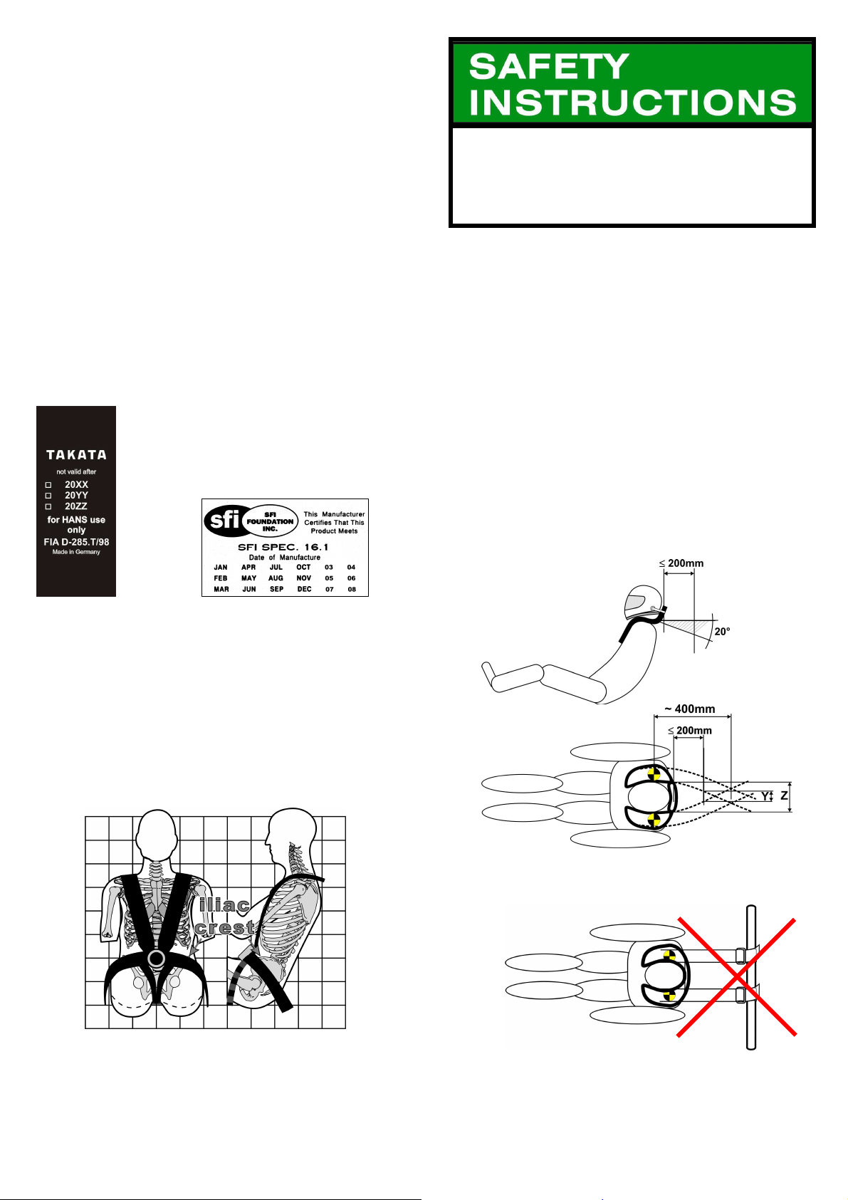
Lap belt straps must be routed over the pelvic bone to stay firmly and tightly in
the crest between the pelvic bone and the upper thigh.
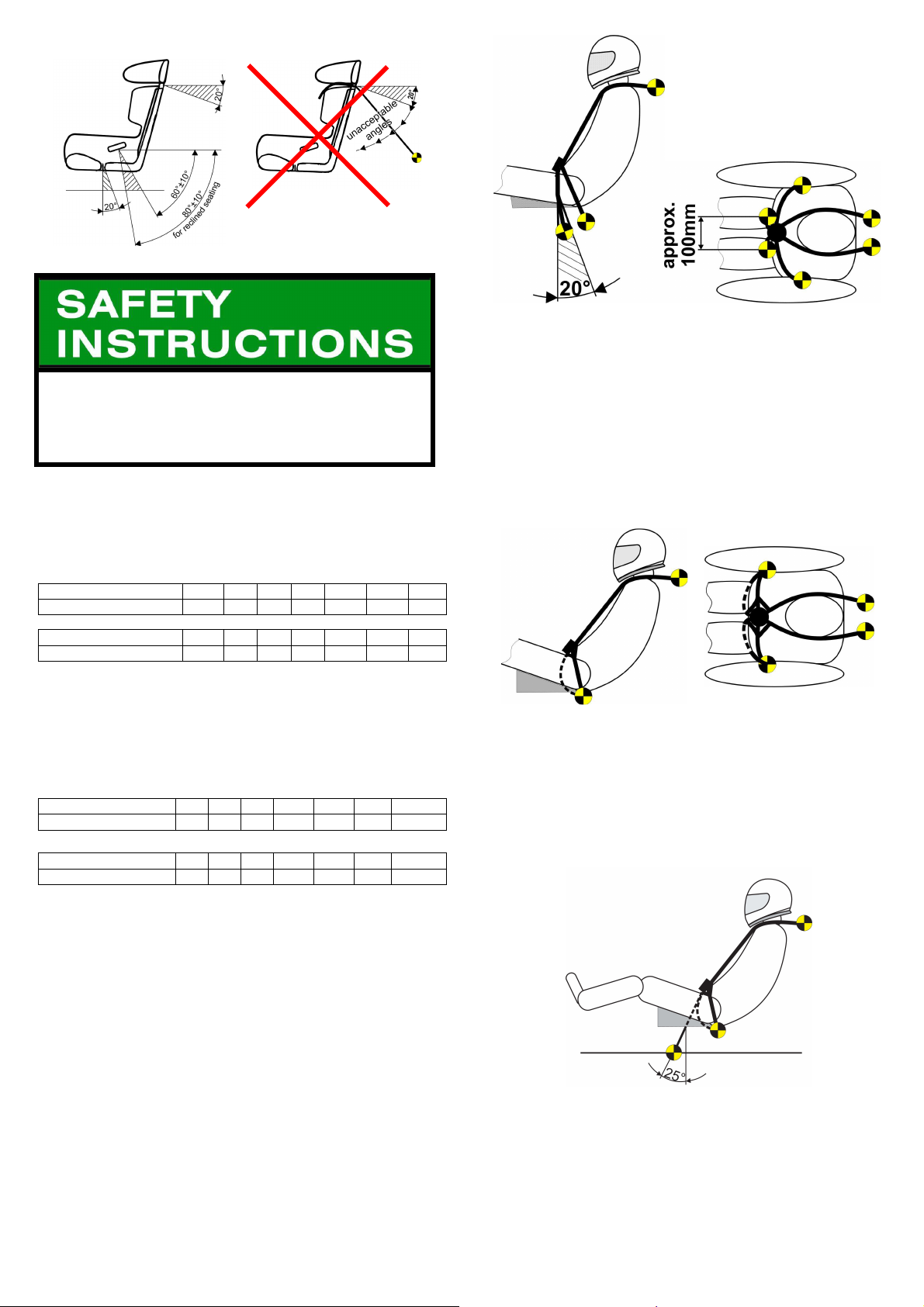
Lap belt downward angle should be approximately 60° measured from the
horizontal, passing through the occupant’s hip joint. This is the suggested
angle for upright seating [15-20° backrest declinat ion]. A higher backrest
declination, e.g. 30° – 40°, as is common in open w heel race cars, requires a
belt angle of 70° – 80°.
Make sure there are no sharp edges [seat structure, seat mounts, chassis]
that may tear or cut the lap belt webbing.
S
HOULDER BELT ROUTING
Shoulder belts must run from the shoulders horizontally or down, at no more
than a 20° angle.
For the best restraint of the occupant’s upper torso, anchor points should not
be further back than 200 mm [8”] from back of user’s seat.
In the event that the anchor points are further towards the rear of the vehicle
[e.g. using a roll cage bar for wrap around attachment] the distance between
the strap anchorages will narrow or even cross over as described in following
graphs.
It is especially crucial to follow this strap routing when a Head And Neck
Support is in use.
3 4
Shoulder belt mountings, located more than 200 mm [8”] from the back of the
user’s seat or angled upwards, are not good practice and are most strongly
discouraged. If shoulder belt anchor points are further back in the vehicle, the
belts should be closer together at their mounting points, even crossing
depending on the distance of the anchor points, but both belt and Head And
Neck Support performance are severely compromised. See Table Below
Shoulder belts shall cross over when the anchor points are located more
than approx. 500 mm [20”] behind the seat backrest.
For 75 mm [3”] webbing wrap around installation the following approx. anchor
point distances are suitable:
Reduce numbers by 25mm [1”] if a Head And Neck Support specific harness is
to be installed.
In metric measure
Distance from seat in mm
Anchor point distance in mm
In imperial measure
Distance from seat in inch
Anchor point distance in inch
side
200 300 400 500 600 700 800
150 100 75 75 -75 -100 -150
8 12 16 20 24 28 32
6 4 3 3 -3 -4 -5
by side
side by
side
crossed
over
crossed
over
crossed
over
F
OR
75
MM
[3”]
WEBBING BOLT ON INSTALLATION
Reduce numbers by 25mm [1”] if a Head And Neck Support specific harness is
to be installed.
In metric measure
Distance from seat in mm
Anchor point distance in mm
In imperial measure
Distance from seat in inch
Anchor point distance in inch
200 300 400 500 600 700 800
150 100 50 0 -50 -100 -150
8 12 16 20 24 28 32
6 4 2 0 -2 -4 -6
Single
crossed
point
over
crossed
over
crossed
over
F
ORMULA MODELS
This anti-sub strap design requires sitting on the straps or having a thin seat
panel allowing the straps running rearwards right underneath the driver’s buttock
and attaching in the region near or on the lap belt anchorages.
The anti-submarining strap routing over the upper thighs and attachment to the
shoulder belt latches with the buckle in between, does not provide a direct load
path from the shoulder belts down to the anti-submarining strap anchor points.
The indirect routing requires a type of preloading of the anti-submarining straps
during a frontal impact. This is achieved by sitting on the anti-submarining straps,
routing them rearwards and attaching them in the region near or on the lap belt
anchorages.
Important: This anti-sub strap design requires sitting on the straps or having a
thin seat panel allowing the straps running rearwards right underneath the
driver’s buttock.
N
EGATIVE G BELT
(7
TH
POINT
)
Used in conjunction with a 6-point formula crotch belt system as an additional
point to maintain the position of the lap belt in “Negative G” i.e. rollovers
A
NTI-SUB STRA P ROUTING
6-
POINT MODELS WHERE ANTI-SUB STRAPS ARE CONNECTED TO THE
BUCKLE
Anti-submarining strap routing shall be vertical down from the groin, and
preferably approximately 20° back,
Anchor points shall be approximately 100 mm [4”] lateral apart from each other.
In case of a low seating position (e.g. in open wheel race cars), this separation
may be reduced since the anchor points are closer to the thighs.
5 6
 Loading...