


TAKAHASHI
Super
Apochromat
TSA-1D2
INSTRUCTION
MANUAL
TAKAHASHI
Thank you very much
for
your purchase
oltha
Takahashi T5A-l02 apochro-
matic refractor. Your first view
will
show
II
color·frae, high contrllst
image
with pin potnt stars.
You
arll
now
ready
to
use your
TSA
bolh Yisually and for
Imagmg.
In
order
to
use
your TSA.l02
to
the limit of
itl
capabilitilll, plll8se read this
instruction manual carefulty
and
familiarize yourself with
all
the features
and
functions
of
this
instrument.
The TSA-l02
has
been
inspected
by factory
technicians before shipment.
If the instrument should
need
service. please
contact your local Tllkahashi distributor for authorized service.
it.
WARNING
I
I
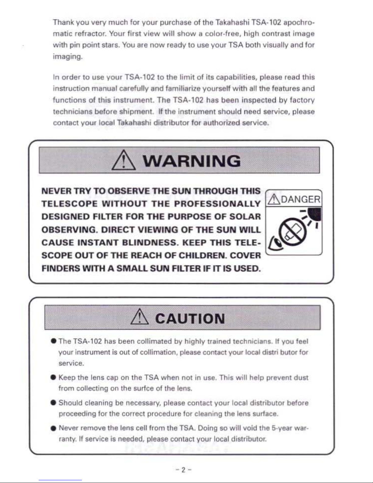
NEVER
TRY
TO
OBSERVE THE
SUN
THROUGH
THIS
TELESCOPE
WITHOUT
THE
PROFESSIONALLY
L!'.DAN~
DESIGNED
FILTER FOR
THE
PURPOSE
OF
SOLAR
OBSERVING.
DIRECT
VIEWING
OF
THE
SUN
WILL
li§)I'
CAUSE
INSTANT
BLINDNESS.
KEEP
THIS
TElE.
SCOPE
OUT
OF
THE
REACH
OF
CHILDREN.
COVER
FINDERS
WITH A SMALL
SUN
FILTER
IF IT
IS
USED.
&
CAUTION
• The TSA-102 has been collimated
by
highly trained technicians. If you feel
your instrument
is
out
of
collimation. please contact your local distri bulor
for
SIIlVice.
• l(eep the lens cap on the
TSA
when not
in
use. Thil
WIll
help prevent dust
from
collecting on the surfce
of
the lenl.
• Should cleaning
be
necessary, please contact
y()Ur
local distributor before
proceeding lor the correct procedure
for
cleanmg the len. lurf&ce.
• Never remove the lens celilrom the
TSA.
Doing
10 will void the 5-yell'
war_
ranly.
If
SIllVice;s needed, please
COl1l3Ct
yOU!
local diSlributor.
- 2 -
Table
of
Contents
Warning & Caution ....·,..· · ····················2
Specifieations ···················· · · 3
Tube Assembly Layout
..·..
· ·
.. ··..
· ·
····4
What is
the
TSA-102 ················ ..··..·,..·..··..··..,5
Attaching Finder & Tube
Assembly
6 - 9
Finder Alignment 10·11
Observation , , ··12-13
Accessorie5
fOf
PhotoNlSUal Application
14-1
9
Care & Maintenance 20
System
Chan
············..···························21-23
SPECIFICATIONS
II
II
========:!
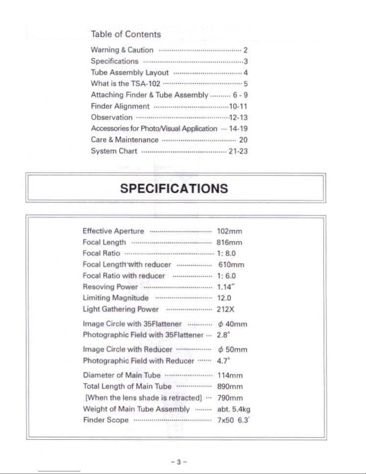
Effective Aperture _ 102mm
Focal Lenglh
816mm
Focal Ratio 1:
8.0
Focal Lenglh'wtth
reducer
610mm
Focal RaIla wilh
reducer
_............
I:
6.0
AesovlngPower
1.14
w
Limiting Magnitude 12.0
Light Gathering Power 212X
Image
Circle with 35Flallerlflr
til
40mm
Photogr.phic
"'",Id with 35Flattener 2.S"
Im.ge
Circle with Reducer
dJ
50mm
Pholographic Field with Reducer 4.7"
Diameter
of
M.in
Tube 114mm
Total Length of
M.ln
Tube
890mm
(When
Ihe
lenl
shade
is
relf.cted]
790mm
Weight
of
Main Tube
Assembly
·....
.bl.
5.4kg
Finder
Scope
7KSO
6.3'
-
3-
'ow.i
....
Knob--_~
~Iinc($)
711
25-])
~
____
Findo. Brocket
,::::j~-Drnt"'"
lock
Kob
~---Ocul.r
Adopter
(50,
B{2-]l
Tube
Assembly
Layout
II
II
=======!I
•
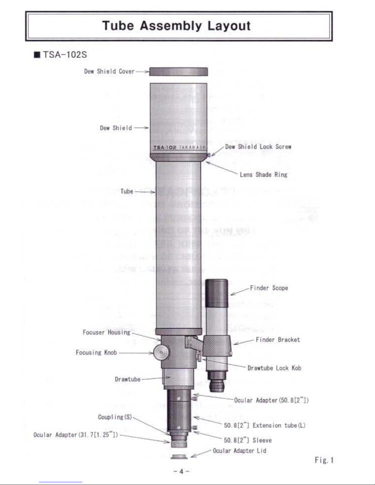
TSA-l02S
0..
Shi.ld
Cove,
!leo
Shield
___
/Dn
Shlold
Loel<
Ser
..
~
LOllI
Sh8ClI
Rilll
AI ~ '
....
'1M
Ocul., AdIPtor(31
-.
Fig. 1
-
--
11,=====w=ha=I=,s=lh=e=T=sA=-=10=2=?===="11
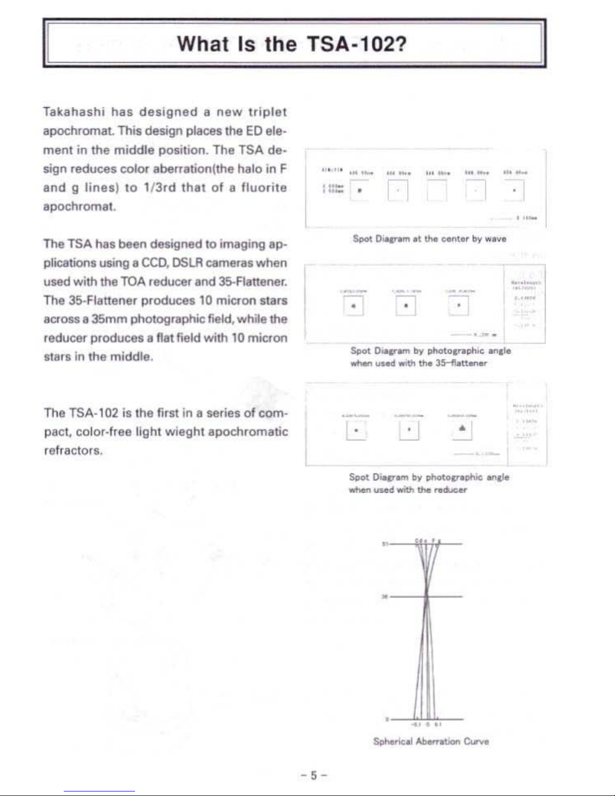
TlIkllhuhi
hll5
designed
II
new
triplet
apochromllL This design
pI3ce,
the
ED
ele-
menl
in
the middle position. The TSA de·
sign reduces color lIberrlltionHhe halo in F
and 9 lines)
10
l/Jrd
that
of
II
Iluorite
:
:::::
.
llpochrom81.
The TSA
has
been
de$igned
10
ill'lltging
ap-
plication. using
1I
ceo.
OSLR
cameral when
used
with the
TOA
reducer
and
35-Flanener.
The 35·Flllnener
produces
10
mk:ron
mrs
•
-
•
-
.-
laota.
35mm photographic field, while the
reducer
P4'oduees.
nit
field with
10
micron
Spot
0--
....
loy
photol
........~ ..,.10
118r.
in
the middle.
........_-""'~-
The TSA-102
lIthe
first
in
1I
series
of
com-
..
-
PIlCI,
Colof.Ifea light
wieghlllpochrOffilltic
~
•
refractor
•.
Spot
o..v-
by
ohotov
.,.10
..............
__
.......
.-
-,-
,ei
-er
mb'y
eA
rf
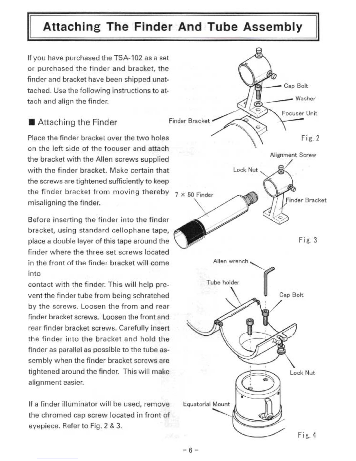
you
have purchased
the
TSA-1
02
as a set
or
purchased
the
finder
and
brBlcket,
the
finder nd bracket Ihave been
shipped
unat-
tached.
Use the allowing instructions
to
at
tach and align the finder.
Attac ing
he
Fnder
Place
the
fi
der
bracke
over
the
two
holes
Fig.2
o:n
the
left
side
of
he focus,e
lmd
attach
the
bracket
with
he Allen
screws
supp
'ed
with
the
finder
bracket. M ke certain
that
Lock
Nu
the
screws are
fghtened
sufficiently
to
keep
the
fi
ndar
bracket
hom
moving
the
reby
7
misaligning
the
finde
.
Be
ore
il1sertinge
111
der
in 0 e
finde
bracket,
using standi;! rd
cellopha
e
tape,
place a
double
layer
of
this tape
around
the
Fig,3
finder
where
the
three
set
screws
located
AI
Ien
wrencn
in
the
front
of
the
finder
bracket
wll
com
.
Tube holder
con
ae
with the finder. This
wTl
help
pre-
i
to
r
C.pBo~
vent
the
mder tube
from
eing schra ched
by
the
screws. Loos·en
the f om
and
rear
:/
finder
bracket screws. Loosen
the
front
and
rear find
er
bra ckat scraws. Carefu
IIy'
se
the
finder
intol e
racket
alnd
hold
the
finder
as par lIel
as
possible
to
the
tube as-
sembly
when
the
finder
bracket
screws
are
tightened a:round
hefindar.
This wil make
alignment
easier.
If
ill,
finder iliumin:ator will
be
used.
remove
the
chromed
cap
screw
located
in
fran
of
eyepiece. Refer to Fig. 2 &
3.
Fig.4
A 19nment Screw
/
-6-
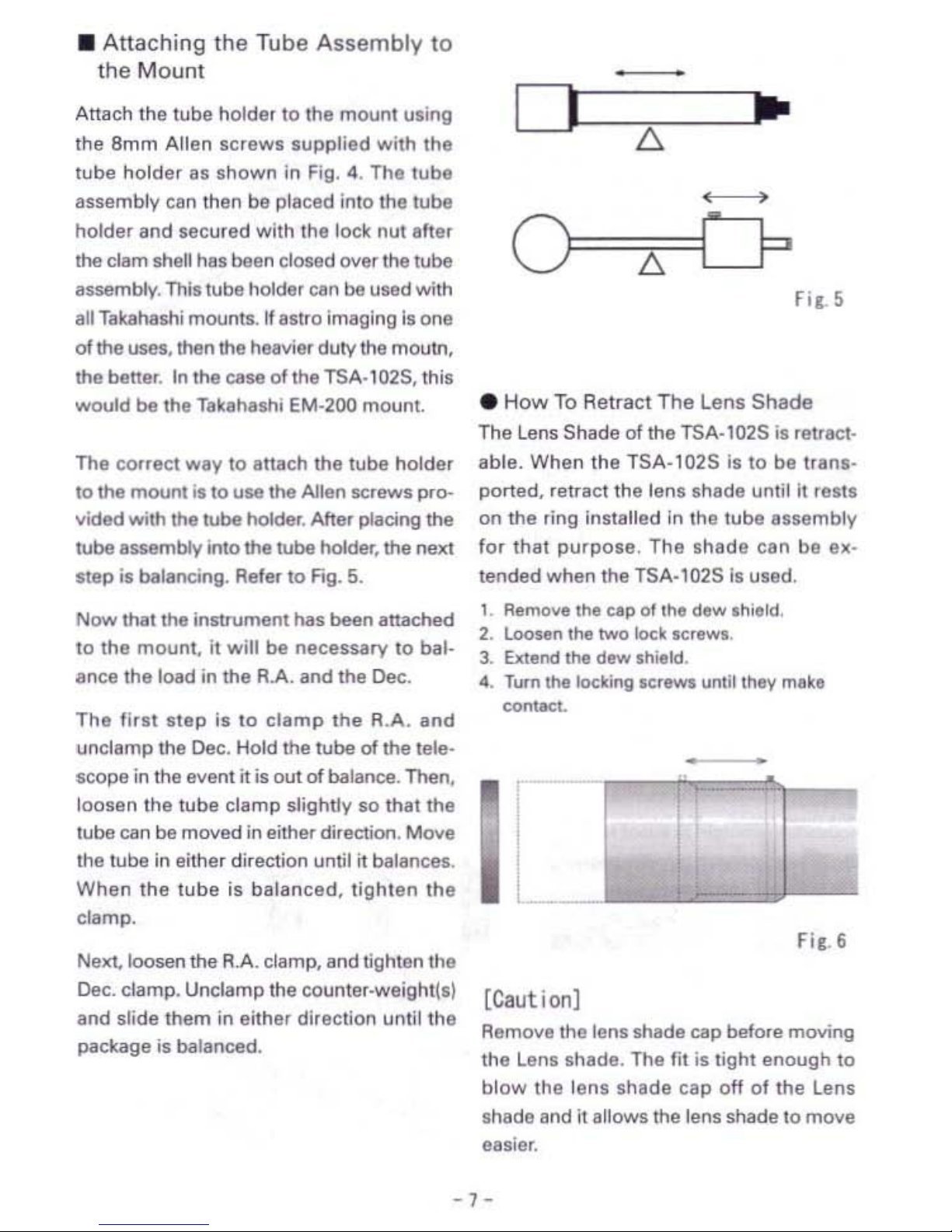
• Attaching Ihe Tube
Assembly
to
the
Mounl
Attach
the
tube
holder to the
mount
using
the
Bmm Allen
screws
supplied
with
the
tube
holder
as
shown
in Fig. 4. The
lube
assembly can lhen be placed ;nlo the lUbe
holder
and
secured
with the lock nut after
the clam shell has been closed over the tube
assembly. This tube holder can be used with
all
Takahashi moonlS.1f astro imaging
Is
one
oflha
uses. then the heavier duty the
moolr1.
Ihe better.
In
the case
of
the T5A·1025, this
woold be the Takahashi EM-200 mount.
The
correct
way
to
altach the lUbe holder
to the moonl
is
to use the Allen screws pro-
vided with Ihe
rube holder. After
placing
the
It.Jbe
assembly into Ihe tube holder, the next
step
ill balancing. Refer 10 fig.
5.
Now
that the Insuument has been attached
to
the
mount,
it
will be
necessary
10 bal·
ance
the
load
in
the
R.A.
and
Ihe Dec.
The
'irll
IIep
is
to
clamp
the
R.A.
and
unclamp the Dec. Hold the tube
01
the tele-
scope
in
the event
It
is
oot
of
balance. Then,
loosen
the
tube
clamp slightly
so
that
the
tube
can
be
moved in either direction. Move
the tuba
In
either direction until
it
balances.
When
the
tube
is
balanced,
tighten
the
clamp.
Nexl,.loosen
the
R.A.
clamp, and tlghtllflthe
Dec. clamp. Unclamp the counter·weightlll
and
slide them
in
either direction until
the
package
is
balanced.
o
..
•
How
To
Retract
The
Lens
Shade
The Lens
Shade
of the TSA-102S
i'
rellaet-
able. When
the
TSA·102S
is
to
be
Ilani'
ported. retract
the
lens
shade
until
it
resla
on
the
ring installed
in
the
tube
assembly
for
that
purpose.
The
shade
can
be
Ill·
tended
when
the
TSA-l02S
Is
used,
1.
Remove the
«Ip
Of
the
dew
Ihield.
2.
Loosen
the
two
lock
Ic,eWl.
J.
Extend
the
daw Ihleld.
•.
Turn
the
mung
SCr,WI
until
they
mak,
Conl8Ct.
Fil.6
[Caut ion)
Remove the
lenl
shade
cap before moving
the Lens $hade. The
fit
is tight
enough
to
blow
the
lens
shade
cap
off of
the
Lens
shade
and
it
allows the lens shade to move
easier.
-
7-

• Compression Ring
Remove the ocular
adapter
cover after the
locking ring
has
been
loosened
by turning
It
counter clockwise. Then, insert
the
de-
sired ocular or
31.7 diagonal into Ihe adapter
and
tighten
the
ocular
rrng
by
tuming
it
clockwise.
• Connection the System Parts
The
adapters
and
the rings ere provided
00
the
visual back to
connect
various
system
parts. Carefully
study
the
&ystem
chert
in
this
book
before
connecting
any
system
parts. Connectioo
of
the
incorrect parts may
prevent
the
telelcope
from
coming
to
I
sharp
focUI
Of
any focus at
all.
Refer to the
Fig. 8
for e lIandard
connection.
/ll.1U
1.0
ee.-
......
Rifle
/
Fie 7
-,
-
• 'ocus'ng
Atter 'nsertingl
the
ocular in
o'e
te'leco
e,
it
is necessary
to
ach"eve
the
best
possible
foe
I
s.
Remember t e atomsphere
willlimiit
the 'g e magnifica ion that can be used
on
any given nig . Us'ng
the
lowest
power
oCliJla
; focliJs
the
image
and
then
"ncrease
th,e
maglnifica'o
by
using
shorter
and
shorterfoca'llength OClI ars I n
II
the desired
magnifica
ion
is reae ed.
This
procedure
all.ows
the
cen erin
of
an
object
at
high
magnification.
Please familiarize
yourself
with
the
following.
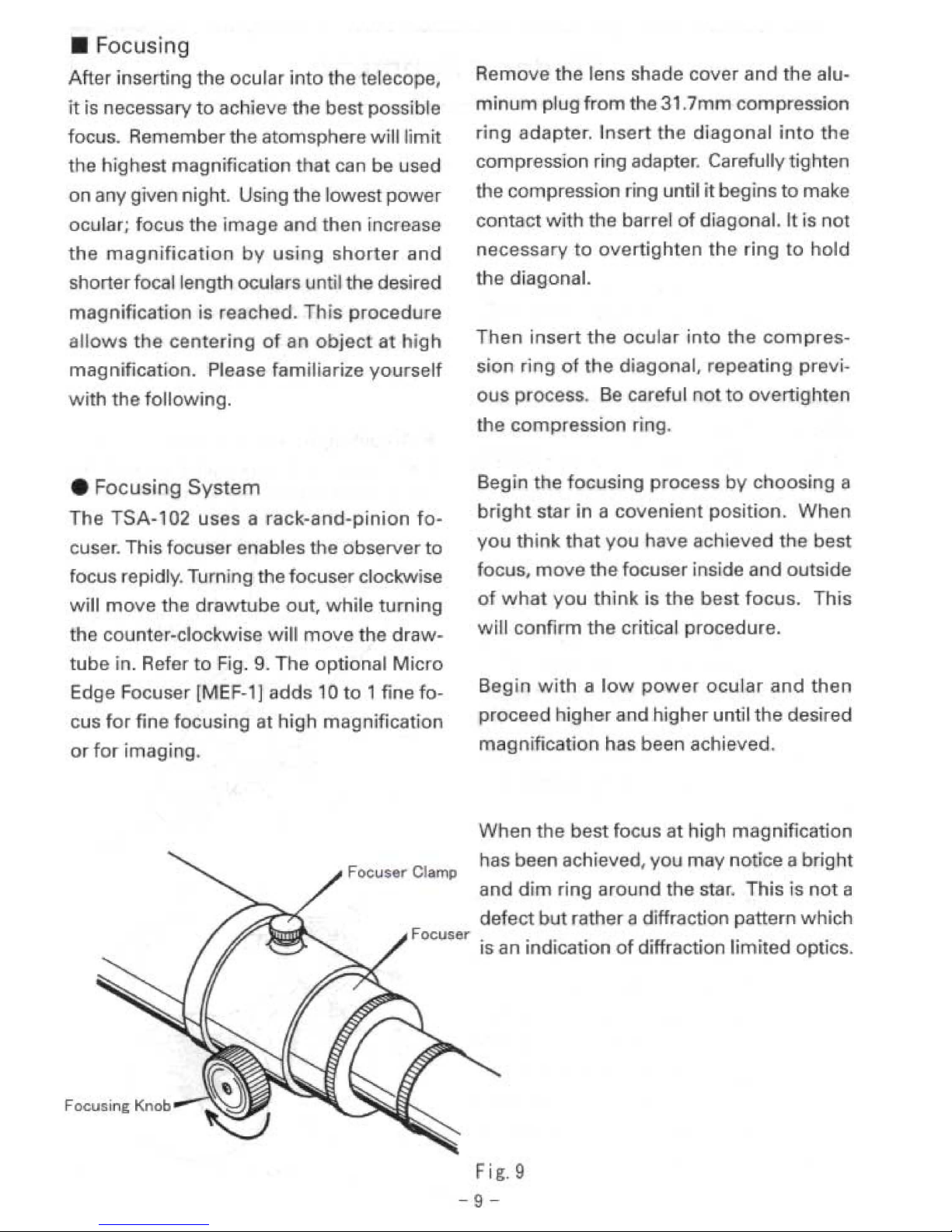
IFocusing
System
The
TSA-l
02
uses iii rack-a
nd-pinion
fo-
cuser. This focuser enables e observer to
focus rapidly. TlIfntng
thefocuser
clockvv'se
w'lI
move
the
drawtube
out,
while
turning
the counter-clockwise
will
move
the
draw-
tube·
. Refer
to
IFig.
9,
The
optional
Mic
0
E ge Focuser
[MEF-1]
adds
1'0
0 1
fine
fo~
eus
for
fine
focusing
at
high
magnification
or
for
'ma,gi g,
Focus r Clamp
Focuser
Remove he lens shade cover and the alu"
min
plug
from
the 31,7 m compression
ri
-9 ada,pet. I
se
he
diagonal
i to . e
compression ing adapter. Carefully ig'h
en
the
co
pression ring until
it
begins
to
rna e
contact
wi
h the barre
o,f
dIagonal. It
'sot
nec,essary 0
overtighten
the
ringl
to
hold
e diagonal.
Then
insert
the
ocular
in 0 th e
com
pres·
sion
ri
9
of
t e diagonal, repeating previ-
ous
process.
Be
ca,retul
otto
overti'ghten
the
compression
r'ng.
Begin the
focusing
p ocess
by
cl100sig
a
brig t star in a
covenient
position.
When
you
hink
that
you
have
achieved the
best
focus,
move
_he
focuser inside and outside
of
w a
you
hink
is
the
bes focUis.
This
will
conti m
the
critica procedure.
Begin
with a low
power
ocular
and
then
proceed
"'gher
and h'gher until
the
desired
magnification
has been achieved.
When
the
best
focus
at.
igh m gnificaticn
has been achieved, yo
may
no ice a
brigh
and
d'm
ring
around
the star.
This"s
not a
de
act bu rather a diffractio pattern which
,
IS
an
ind"ca
ion
of
diffraction Ii 'ted
,opt.ics,
fig.9
-9-

g
II!-I
=====F=i=nd=e=,=A=I=i=n=m=e=n=I======,11
tr::::_::-
umnnnnmn_n_m:Cr-"':c-~
BeIDl"
Ihe
finder
is
placed
in
the
finder
holder,
use
plastic clee,
tape
lind
tape
the
finder
with
two
layers
10
prevent
the
lube
from being scratched
by
the
',onl
finde,
set
screws.
A finder is 8 useful tool.
1\
permits
the
pre-
cise
centering
of
an
object
in
the
field
of
view. The 6.3' field
of
villW
allows
the easy
centering
of
an
object
to
be
viewed
Of
pho-
tographed.
The TaKahashi
finder
uses en
interrupted
crosshair
which
is
designed
10
allow
the
easy centering
olin
objecllo
be photo-
graphed or observed. The
wide
field
of
the
finder makes tlla finding
of
an object easier,
therefore,
it
il
impofl1nt mat !he finder lind
Ihe lelescoep
be
in
alignment. The follow·
ing
procedure
can
be
used
to align
the
finder.
• Alignment
Procedure
1.
Plllce
II
low power
eyepiece
in
the
tele·
1COpe
lind
center
a bfight
'tar
in a con-
venient
part of
the
sky.
00
not forget to
engage
!Ile motor drive to keep
the
Il8r
centered.
If this procedure
il
done
in
day-
light,
use
an
object
that
II
lit lellst
one
mile
i1wilY.
Loosen the lock nuts
on
the
finder brllCkelllnd lIightly move the
'Iar
to
the
center
of
the
field using
the
ad·
justing IIlignment screws.
FiC.IO
2.
Then
use 8 higher
msgnific81ion
.'1'11-
pieee
and
repeallhe
procedure
by
cen-
tering
the
object
in
the
field
01
view
01
the telescope
end
then the finder.
Con'
tinue this
p.oeets
untillhe
hlghes'
pos.
sible megnifiealioo has
been
used.
•
Adjusting
Screw
Procedure
1.
Tum
1111
the
lock
nutl
until they rellch the
head
01
thlllllignment
screwl.
Fi
I.
11
v
....
F..ld
of
F..-
FiC.12
-
10-

2.In
orde'
to
move
the
crosshllir
In
the di-
rection
01
the arrow, first 100Mn
Ia_
(al
and
lighten
(pushl
the
finder wIth
iCfew
Ie).
This procedure
wiI
mOVil
the
cronhIiI
in
the desire cWecbOfl. TM
lOP
of
the
tinder WIll
move
in
the
~I.
dit"ectlOn
iIOd
the
obtect
wiI
rnooq
in
!he
di'eetlon
of
the
slMOer
errow
Refer
10
Fig.12.
3.ln e Slmililr
felhion
the
direction of
the
mo
....
m.nt
of
th.
linder
tI
made
by
ed-
hlsling
the
Ihr
..
Krewa.
Le.m
Ih.
r.lationship
b.tween
the mo...
e-
m.nt
olth.
three
.djulling
scr.WI.
II
the
linde'
c.nnot
be
moved
In
the
dlli"d
di-
reetion,
1000n
th.
kN;;king
nUll.
• RetIcle Illuminator [Optionall
Thl1x50
finder
!NIs
provision
lor
.n
OJ)-
tion.l
ret>dl~.
If
an illuminator will be installed.
"move
the
elP
ecrew"
the
end
of
the finder
and
instllN
the rebCle illuminator. The illumina-
10' mak
..
the
centering
of
dim
obj.cts
elSiet'.
In
order to Ium Ihe iIIuminetor on. turn the
knob
clockwill.
Th.
knob
will
click
when
the
illumInator
turns
on.
As
the
knob
is
turned,
the
r.licle
wi.
brighten. Adjust the
knob
to
the
delH'ed
brightness.
Turn
the
knob
countef-dockwlH
past
the cltck to
tum
the
-..ninator
off. Refer
to
Rg.13.
• Replacing The Battery
Before ch8nging the baneries in
the
~lumi-
nator.
please
be
certain
to
turn
it
off.
Un-
lICfew
the banery
holdef-
as
shown
in
F'rg.14.
Remo....
the
old balteries
and
insert
new
one
after they
hr.ie
been
wiped
with.
clean
dry
cloth.
Check the poI;,rity of
the
ban".
ies
belore
inlMlrtiflll
them into
the
holder.
Use
IWO
silv...
(V76-PKI
or equIValent bal·
teries
.
HoW
__
_
-Mtt.y_
, .
Fia.
13
-11-

Vis a
lApp
.icatio
IS
'.
Determining
Magnification
The
magnification
of
any
ocular
used
wit
the teIescope
c-a
n be caleu!a ed by
us'
9 the
fol
owing
tomura.
Therefore,
sharterfocal
leng h eyepieces
wil
produce
the
highe
magnification. On a
night
()
very
good
seeing
'he
TSA-102
telescopes
can be used a 100X
per
inch
,of
aperture,
and
on
some
nights,
of
exceptional
seeing,
120X
more.
T ese rare
nights
of
exceptional seeing
will
reveal
fine
planetary
filaments
and
small crater ets
on
the
moon.
At
the
lowBr
end,
about
OX
per
inch
or
so
wil
produce
breathtaking
wide
field
view
of
nebulae
and
comets.
• Compression Ring Star DiagiOnal
The
31.7 ( 1/4
m
l
di
gon I prism is inserted
into
he
compression
rin.g
adapter
,at
the end
o
the
facuse
a d
tightened
ntil i holds
t e
diagonal
in
place. Then
the
acullar can
be
inserted
into,
he
compression
ring
adapter
of
the
diagonal
and
tighte
ing
te
compression
to
hold
he
ocular.
Lunar observation
The
moon
iis
an exceillen 0
ject
for
begi
-
ners and advanced amateur astronomers as
well.
The
entire
Moon
Gan
be
viewed
at
about
50X,
but
on
cle r night near full 'Moon,
it
is best
to
use a
58
glreel1, 3N5 0
va
jab'le
palar"zingl
filter
to
view
he
ef!ire
dis
.
Using
higher
mag
iflcartfon on
the
Moon
is
any
phase 0 ee
detail
will
al
ow
t e
ob-
serve
to
see
smaller
and
smaller
detal
ay
structures, and
rilles. For
this
type
of
,ob-
servation
he
filter
is
normally
removed
be-
e use as
the
magnification
'goes
up,
the
image
brigh
ness decreases.
The
ul
ra
high
co
ntra
st
irnages
prod
uced
by
th
e TSA-102
will
amaze
the
observe.
In
order
for
the
observer
to
enjoy
a va
iili-
ion
of
magnified
observation
without
troubllesome
attaching
and
detaching
oc
Irs,
5'-\lJr
et
ocular
holder
is opHonally
available,. Refer
to
the
system chart.
Plan
etary
observation
he
TSA-l
02 ·s pa
,icularly
suited
for
plan-
etary
observation.
The-
high
cont' ast,
very
sharp
images
will reveal a wealth
of
pl:an-
e ary detail.
In
order
to
see
his
f"ne
deai
the
nigh
S!
ouild be
very
steady.
If
the stars
at
the
ze·
nith
twfnkle a good
bi,
he
e
planets
wm
Ilook
sharp
at
low
m'agnifica1:ion.
When
the
star a
he
zenlith
is
steady hen high
magni-
-12
-

Seeing
fica
ion
ca
n be used a reveal a wea I
the
detail. Magnifica io s of 100x per inch can
be
used.
These nights
of
steady seein will also
pro-
duce
fine
images
using a digital
SLR
or
a
35mm
camera using Fuji Velvia slide
film.
Effective focal ratios in excess 0
f/l00
can
be used.
• Observation
of
deep sky objects
In gene
aI, obse
v'ng
deep sky objects re-
qu'res
a
low
power,
w"defield
ocular
whic
produces the maKimum rightness. On he
o her
'h
nd,
observing g'lobular clusters and
small neburae requires high magnification,
his is particularly true in ci ies
with
high
sky brightness, High magntfication will help
reduce
the
sky background and hence
im-
prove
th
contrast
necessary
to
view
the
object(sl,
Astra Imaging
Focusing
is he
mos
critical
elemen
of
making great
as
0 images. Once critical
fo-
cus habe been Ichieved, then outstanding
imagies can be made. It is a
good
practice
to
recheck
critical
focus
before
'mage
is
made.
Eyepiece P
ojection
ImBging
When
you
want
to
make lunar
or
planetary
images the TCA-4 is designed
to
make eye-
piece
projection
images easier.
The
TCA-4
will
accept
any
Takahashi
LE
31.7
(1
11
")
ocular and variable
ea
ure sli ing tube gives
the
imager
la
itude in de
ermining
he size
of
he Inal image.
It
is
important
hat
high
magnification
im-
ages
of
the
00
and lanats require good
seeing. The
method
for
determining
the
qu
lity
of
seeing on a scale
of 1 to
10,
wi
h
10 being perfectly steady seeing is
to
look
to
the zeni h at a brig ht star. If
it
is
twin
ling
rapidlYI
he
seeing is
between 1to
4. If
the
twinkling
is
moderate
this is 5-6.
If
the star
twines
slowly
to
no twinkling,
we
have the
7
to
10
night. The
I.ess
twinkle'
he better.
Ll
Cautions
When taking high m gnification photographs
of
the
Moon
and planetsl pay
careful attention 0
blance.
Rebalance
the telescope w e
the. object is placed
in the center
of
the camera.
If the
telescope
is
moved
to
another
object, then rebalance
it
in the position
in
which
the
photos
will
be taken. Do
not
use the camera shutter; use
the
~hat
trick-
a.
blac
card place
over
the
lens
shade before the shutter is
set
on bulb,
After
he
vibr,ion
has stopped; remove
th
black
card
fa
'he
duration
of
he
photo,
which
will
normal,ly
be'
sec-
onds.
-
3-
I

Accessories for Photo/Visual Application
.31.7
Compression
Ring
Diagonal
and
Mirror
Diagonal
Both
of
Ihese diagonals take up different
back focus. This
is
noted on the diagram.
The 31.7 prism diagonal
will
require the fo-
euser
10
be racked
out
fUrlhe
•.
FIt:.
16
311_~
Fi,.IS
•
2X
Barlow
lens
This Barlow
lens
was
originally d81iigned
for
the FS
Series
and
it
can
be
used
lor
the
1SA
fOfvisual
use.
This
short
BarloW
can
be used
with the
11/4"
diagonal or
2~
mirror diego-
MI.
-am
3110..-.
AdoQt
..
","-'0
so
..
En-
T-OO
-,
Fit:_
17
- 14 -

• 5-Turret
Ocular
Holder
5-turret Ocular Holder
is a unique
ocular
holder
Ihal can
attach
live dilferenl 31.7
ocular5 to view an object with live dille,ent
magnifications quickly
by turning lhe hokle,.
Rele, to
FIg.
18,19.
}J-'
--10
Fie.
18
........
• Twin Viewer Binocular Viewer
Tl>e
Twin
Vlewer is a
45"
b1noc:ul., viewer.
The
two
compression
ring ocular adapters
insure
thaI
me
optical
axes
are
all
coinci-
dental
for
the
best
possible. The buih
in
2x
barlow lens
and lE oculars
will
provide ex·
cellent
views
ollhe
Moon
and
planelS
and
when
Ihe
ba,low
is
"moved,
wide
field
views
of
deep
space
objeClS.
Fie
19
-
-
15
-
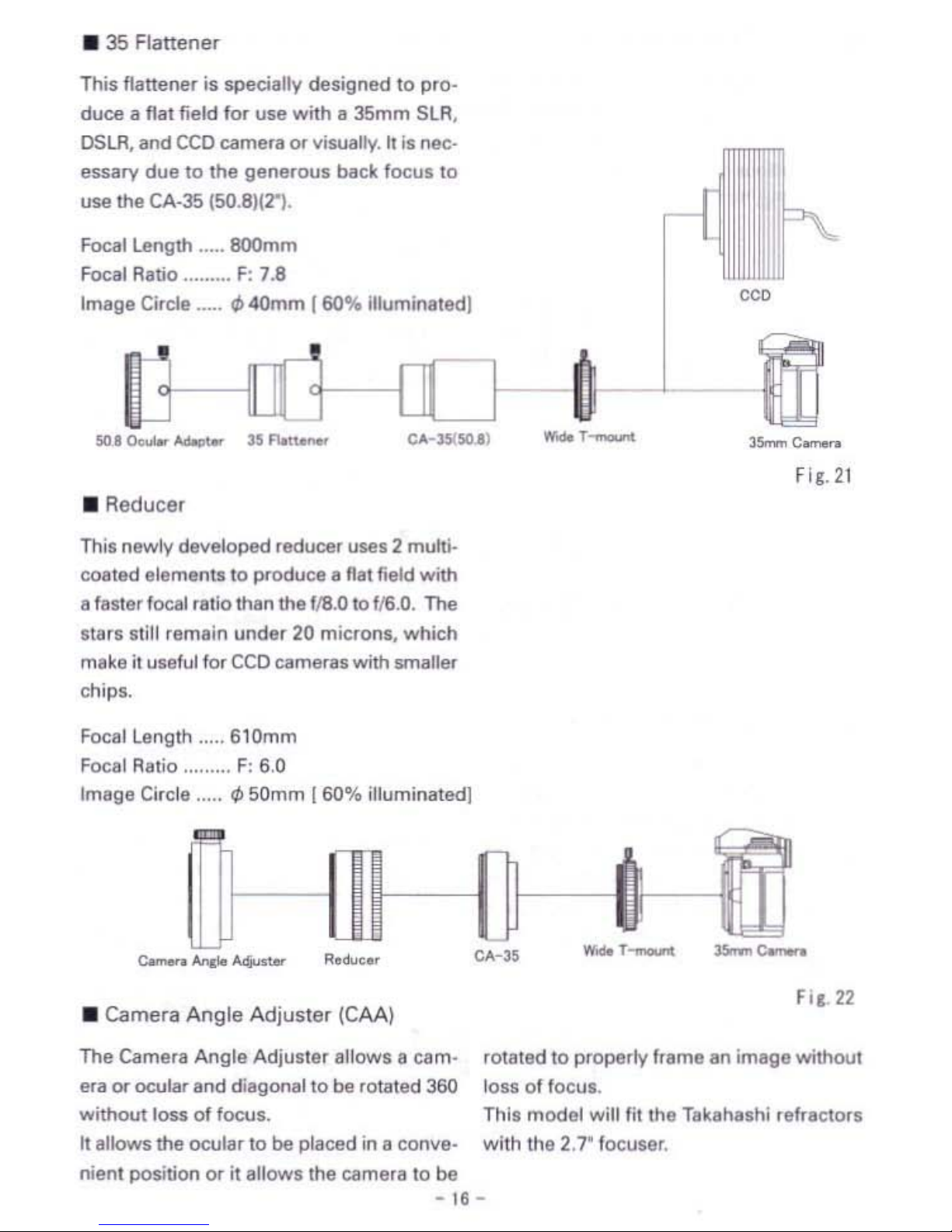
•
35
Flattener
This flattener is specially
designed
10
pro-
duce
a flal field for
U511
with a
36mm
SLA,
DSLR,
and
CCO
Cilmllfil
or
visually. It is nec-
essary
due
10
Ihe
generous
back
locus
10
use
lhe
CA-35 (50.8IfT).
Focal Lenglh
SOOmm
Focal Ratio
F:
7.8
Image Circle
~
40mm r60%
illuminated]
""
•
SO,I
0.0..--
........
r'
Fle.21
•
Reducer
Thil newly
developed
reducer U5IIS 2 multJ.
coaled
elements
to
produce a Rat
fillld wilh
a fasler focal ratio than
the
f18.0
10
116.0.
The
sterl
Itill
remain
under
20 microns,
which
mike
it
useful
fOf
CCO
cameras
with smaller
chips.
Focallenglh
,
6tOmm
Focal Ralio ,
F:
6,0
lmlge
Circle
I/J
50mm
[60%
illuminated]
,
....
•
Camera
Angle
Adjusler
(CAA)
The
Camera
Angle
Adjusler
allows a
cam·
era
or
ocular
and
diagonal
10
be
totated
360
wilhout
loss
of
focus.
It
allows
the
ocular
10
be
placed in a
conve·
nient position
or
il allows Ihe
camera
to
be
-
16
Fi,l.
22
10lated
10
properly
Irame
an
image
wilhout
loss
01
locul.
Thil
model
will
IiI
the
Takahashi refractors
with
the
2.1' locuser.
-

• CA·35
Th"e
are
IWO
dillerenl
35mm
camela
adapter
availabla
lhat
will allOw an SLR/
OSLR
and
CCO
camera
to
be
anached
to
DO
B m
the TSA-l02.
a. CA-35tSO.8l
101
prime locoa.
Refer to
Fig.
23
b. CA-3S(TSA-l02l
101
redocer loco•.
Relelto
Fig.
24
""
Fie
23
[]J-
""
Fie
2•
•
T·Moont
& Wide
Moont
T·Adapters
The T-Moont
isosed
to
c:onnee:t
to
the
TeA-
4 eyepiece projectioo &dapter lor high mag-
nification
photos
and
CCO
images
01
the
Moon
and
p1anels. Relel
10
Fig
25
The
Wide
T-Mounl
can
be
used
lor prime
Fie
25
locus,
reducer, 35·flattener photography.
Rerer to Fig.
26.
Fie
26
-11-

.TCA·4
This variable eyepiece device attaches
eel-
ily
to
the
TSA
fO' high quality high magnifl-
Cltion
photol
01
the
lurface
of
lhe
Moon
end
plenell.
It
can
be
used
with e
film
or
ceo
camera. Refer
to
Fig 27.
III-f
• MEF-l
The
Mic.o
Edge FoeuMr
it
en
ot)tton"ly
eveiteb'e
10
10
1 fine
locus
enaenm.,t
thM
,.mIits
10
to
1
rone
focus
for
Cf~
foeus.
log
fl)(
~lf"Ig
I)(
Ngh
m.gnmbOn.
• FOR-l
FOR-1
is
very
wnventent
device
to
enach
end
6etadl the rmdeo quickly.
Onee
it is
set
on
the
focuSlf
housiog, you can a"ecto and
dellch
the
linde,
quickly by
thumb
turn
screw
The
linder alignment
'lIJfIIinulmost
the
lime
in doing so.
FIe
28
Fie_29
-
11-

Sun Projection Screen
The hIgh quali optics
of
the
TSA-102 will
provide oUitstanding
images
of
the
Su
,It
is
best
to ;se
hig
h quality 9
lass
filters
or
H-
alpha
filter.
ever
ob
e e
the
sun
directly.
This
will
ca use insta nt
bli
dness.
Cover
your
finder with
two
layers
of
al:uminlzed - y ar,
or
an
Dpaque
coVer
mder
to
allow
t e
ob-
server
to
can
_e
the
sun.
Sun
Projection
Observation
Sys
-em
Sun
Projection
Screen
Accessory Holder
Ring
ig.30
-
19-

Ca
·ance
Before A
empf, 9 To
Clea Your
Opfcs,
Contact
Your
ocal Distr"bu
or
F,or
Pre-
cis,e
Inst
l1ction Or Advice
On
How
To
Proceed.
If
the
front
ens
of
the objec ive as d'
st
or
di
particles
on
it, use a
large
hand
powered
blower
to
remove
tine
particles.
Under
0 circumst nees
should
dust
be
removed
by
any
other
means,
rubbing
the
surf,ace
will
cause scratches.
If
the
lens
must
be
cleaned, be certai
that
a I
d s
and
dirt
par
ides
have
been
r'e-
moved
by
using a blower.
Then,
using
cotton
sws,bs s'ig htly
mots
ened
with
lens cleaner, gently clean t e particles off.
• REM
EMBER,
DO
NIDT USE A
_'
FORM
OF
,CANNED
AIR
TO
REMOVE
T E PART CLES.
This predue is
v,ery
cold and 'could harm
the
front
lens
of
the' obje,ctive. Be cer-
taill
tna
ta
dew
cap
is
removed
before
atlemp, ·ng
to
clean the objective. Use
the
following procedure,
if
he
front
and rear
s'u
races
0
the
objective
mus
be
,cleaned.
Dew
Shield
Fig.31
1.
Remove t e
dew
shield
'fl'O
the
cell
by
turning
i counte
-c
ockwise. In case
of
the
dew
shield is retractab
e.
loosen the
lock screws and
remove
it.
2,
IRemove he
sc
ews
tha
a,
ach
the
ob-
jac
'fve
to
the celli. These
,are
he shorter
Screws
with
the
la
9€ltheads.
Alw·
ys
kieep
one ha d on he objective
as
hese
screws
are remove 0 eep
it
from
fal'l-
ing.
As
you
emove
the
objecfve
cell,
ma e two
marks
on
he
cell and base so
that
i
will
be
placed
back in its original
position after cleaning.
In
the diagram the
s,crews
r,emoved
re
calJ,e,d
"pulling
5,crews".
3.
After cle ning,
an
eh
the
objec ive
again
to
the
base,
aligning
the
marks madle
on
both
when,
he
objecive
cell
w.as
re-
moved.
lif
thi is
ot
done,
the telescope
win
not
be properly col imated. I
you
feel
that
you
do
n01
w'shto
do
this
proce-
dure,
contact
yom
distributor.
They can
do·
is
procedure
and
re
ur the
inst
u-
mentto
yo
.
Do
notry
to
disassemble
the
lens cell
fo
·he lens c
€lan"
9,.
It will be impossible
to
collimate
the
objec
've
without
the
specia
Ico
iiimatar.
If
the
telescope
is
used
in
conditiolllof
high l.Jmidity, b
ee
,sin
ha,
it'
ta e
indoms
and
dr'ed
out
before it is sto ed.
It
the
dew
has
no
been
dried
and
the
ins
rument
is stored,
there
will
be
a
halrm~
ful
:residue left
on
the surfaces
ofthe
tele-
scope.
Leave
the
I,ens
cap
off
until
the
objective lens
i's
totally
died.
-
20-

II
System
Chart
II
•
Photo/
Visual System Chart
I.
CM
(TkA30200]
13.
50••
SIN
••
[TIl;POO113]
14
c--.,
(SXTIV.OO103]
t-
JJJ-''-----r''''
"
liS
R.o..c:
...
tTM31580S]
32.
T-mount
33
Wld.T-mount
~
35mm..-..
31
TCA-4
[TKA00210]
46
317
0.:......
adapt..r
(TXPO(llQI]
47
0.:
.-(311)
..
46,
Oeol
(501)
49 J1.7
Di
••
_1
poi""
(TKPOO541)
&0
Ext~TO"'I.I.
[TxAoonsl
70.
50.8
OculI'
_pto,
[TIIP27110]
11 L bIoI'''''''
tuboI
(L.)[TKPJ
1112]
1(
DiI(OMI
mim>r
(TIWlO5(3)
75.
Adlpt
...
(OldX31
7J(TKAool11]
80S 35
fl.tt..-
[n(AJ
15.82]
88. ceo
cam
....
•
..
dj
"lIt-
..
h"
.....
',l
......
lU._l1l
..........................
IotIloo
__
•
__
SUVOSUl
__
Ioo_
•
__
X....
,11 •..-
_lloo,pooI
~.l.t
-
21
-
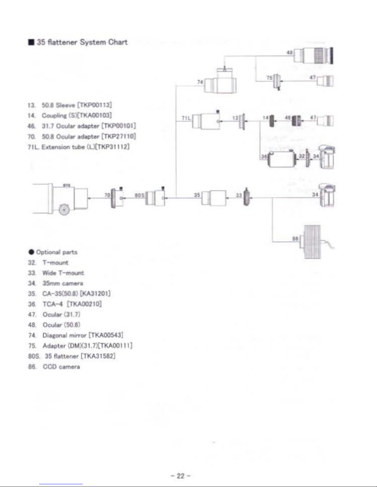
• 35
flatte~
System CNrt
"
UTI]
13
~I
sa.-
[TKPoollJ]
I.
c-;'C(S:{Tl(AOOICl3]
•
...
311
0cWr
[1l<POO'Ol]
~
"U-
...
"II-
'q
I
70
50.1
00uI.-....._(TKP21"O]
TIL.
~~(L.XTKP311n]
•
........
-
tt
._
"11
JJ
WOMT
__
"
-~
35
CA-35(501) (KAJt2(1I]
]I
TCA
.... ('l'XArmIO]
.,
0c0.0IeI'(311)
.8.
0.:..-
(!oO
I)
H
O'
•
.-I_~3]
75
Aliollt.,(OMX311)[nWX11111
lOS n n.u
.......
[lltA31582]
II
CCD_.
-22-
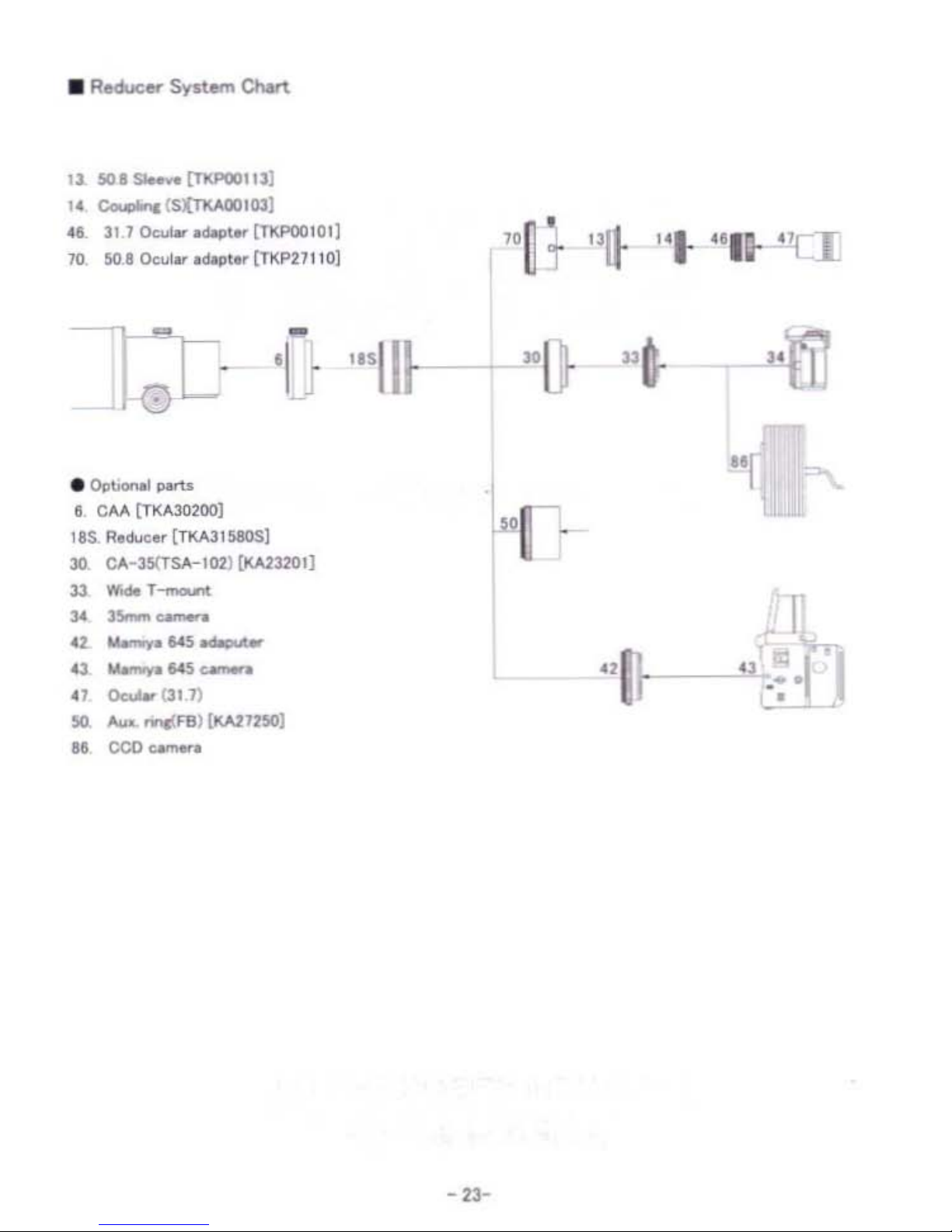
lJ.
so
......
[TXPOOllJ]
1.
COo
'C(S{nv.ooIOJ]
.1
111
O<:ulw
adopt
lTltF'OOI01]
70
501 Ocuiw
adopt
[T1tP211
10]
'I
e
"'III-
"
•
OIIt>onaI
~
I
CM
[TKA302OlI]
liS
R.d\><:
...
{TM3151OS)
30. CA-3S(TSA-HU){KA23201j
13
ww.
T--..-r4
J.I
J5oowoo
__
U --."'5 t _
...
~
~.IoC5
__
.1
ee.-
(311)
SO,
.......
nrc<F8)
{KAz115O}
II
CCO_.
-23-
 Loading...