


Equatorial
Mount
EM-400
lemma
2M
INSTRUCTION
MANUAL
TAKAHASHI

Thank
yoy
lor
yoy, purchase of
the
EM-400
Temma2M
moon!. This highly
sophisticated moynl is
perle<:lly
$uiled
10
any number of photo/Visual ap-
plications.
In
Ofd8l10f you to be
able
to operale
the
EM-400
Temma2M
to
the
limit of its capabilities, thoroughlly
read
this
manual
and
familarize yoy,.
self wilh
the
COffect
ope/alion
of
I
..
many fealures
and
functions. Properly
used,
the
EM-400
will dellve. ali/etime of operation.
WARNING
I
it
I
NEVER
ATTEMPT
TO
LOOK
AT
THE
SUN
&,DAN-5i!
DIRECTLY
THROUGH
THE
TELESCOPE
OR
FINDER.
OOING
SO
WILL
CAUSE
IN-
STANT
BLINDNESS
DUE
TO
THE
INTENSE
@'/
LIGHT
AND
HEAT
OF
THE
SUN.
IS
CAUTION
I
6
I
• When
you
place
the
tube assembly
into
the
tube holder,
do
not
over
tighten the
tube
holder clamps.
Doing
so could
distort
the
telescope
tube and cause
the
telescope to decollimate.
• Place the
mount
on
the
flattest
ground
at
the observing site. It
is
im·
portant
that
the
tripod
be set on the flattest
ground
available to
pro-
vide a stable base for the
mount.
• Exercise great caution when sliding the 8
kg
counter weights on
to
the
counter
weight
shaft and after this has been done attach
the
safety nut
to the
bottom
of
the shaft
to
keep the counter weights
from
coming
off
the shaft. The
counler
weight
could cause severe damage to anything
it falls
upon.
• Never
under
any circumstances
allow
the
mount
to
get
wet
from
rain.
Moisture
will short circuit the electronics and wash out the lubricant. If
rain threatens,
immediately
take
the
mount
down
or
cover
it
with
a
waterproof
cover in
the
event
the
onset
of
the rain is rapid.
-2-
CONTENTS
Warning & Caution for safety operlltion " 2
Specifications 4 - 5
layout
of
the COnlrol80l( 9 -10
Functions for the
R.A.
and
the Dec. clamps
17
Polar Alignment
in
the Nouthern Hemisphere
19
- 20
Selting the Reticle Offset(1'
21·22
Motor Drive Operation " "
26·27
Contents _ 3
Layout
01
the EM-400
Temm1l2M
Equatorial Mount 6
Features of tha EM-400 Temma2M Mounl 7
Layout
01
the Control Panel 8
Precautions
11
Assembling the Tripod
12
Mount & Counter Weight 13
Tube Holdel
14
DisaSMmbling the Mount ,
15
Balancing
16
Al:imuth & Altitude Adjustment 18
Sett;n9 the Reticle OffMtl21 23
Polar Alignment
in
Low
Latitudes
8elow
20· 24
How
to
Use the Motor Olive
System
25
Procedures for Go·To Operation " "
..
28·
29
Auto Guide Connector 30
-
3-
11.1
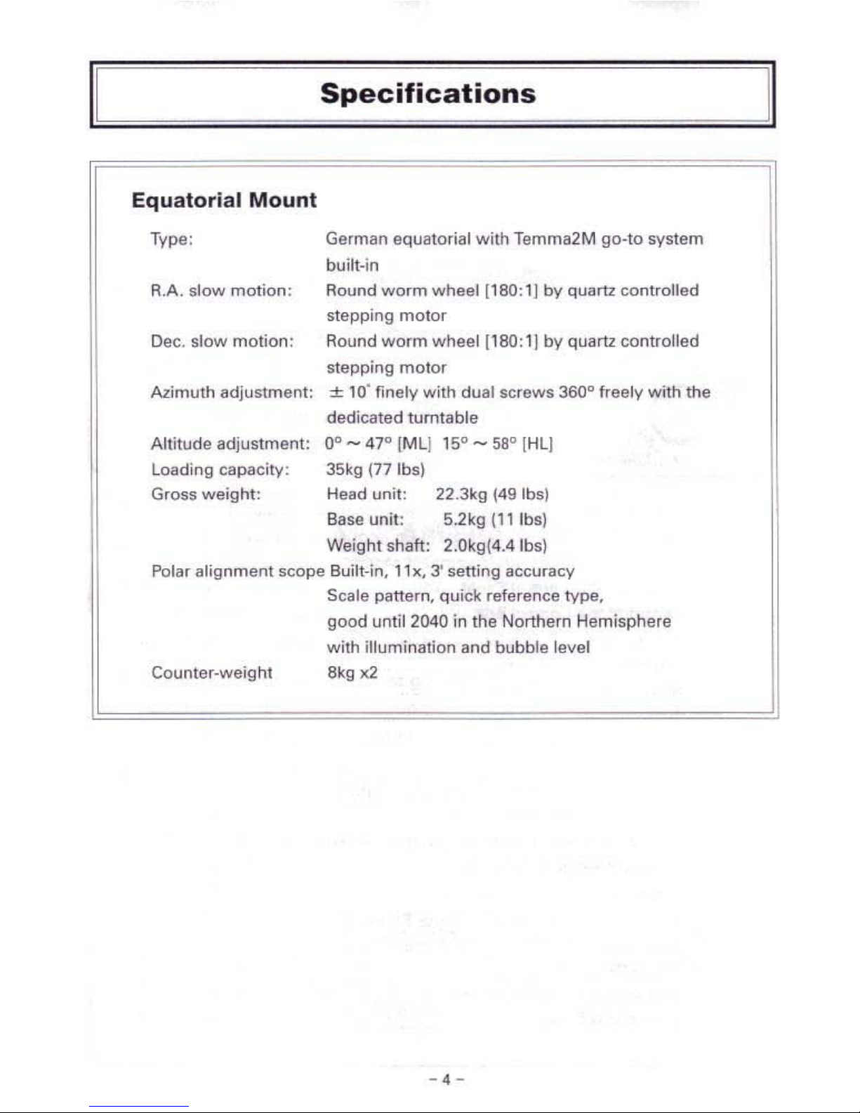
~~~~~~_s_p_e_C~if_iC_a_t_i_o_n_S~~~~~~=,11
Equatorial
Mount
Type: German equatorial
with
Temma2M
go-to
system
built-in
R.A.
slow
motion:
Round
worm
wheel
[180:11 by quartz
controlled
stepping
motor
Dec.
slow
motion:
Round
worm
wheel
[180:
1)
by
quartz controlled
stepping
motor
Azimuth
adjusunenl:
± 10·
finely
with
dual screws 360" freely
with
the
dedicated turntable
Altitude adjustment:
Dc _ 47°
(ML)
15° - 58° {Hl]
Loading
capacity:
35kg (77 Ibs)
Gross
weight:
Head
unit:
22.Jkg
(49 Ihs)
Base unit: 5.2kg
(l'
Ibs)
Weight shaft: 2.0kgl4.4Ibsl
Polar
alignment
scope
Built-in, 11K, 3'
setting
accuracy
Scale p.mllrn, quick reference
type,
good until 2040 in the Northern Hemisphere
with
illumination
lind
bubble level
Counter-weight
8kg
1(2
-.
-
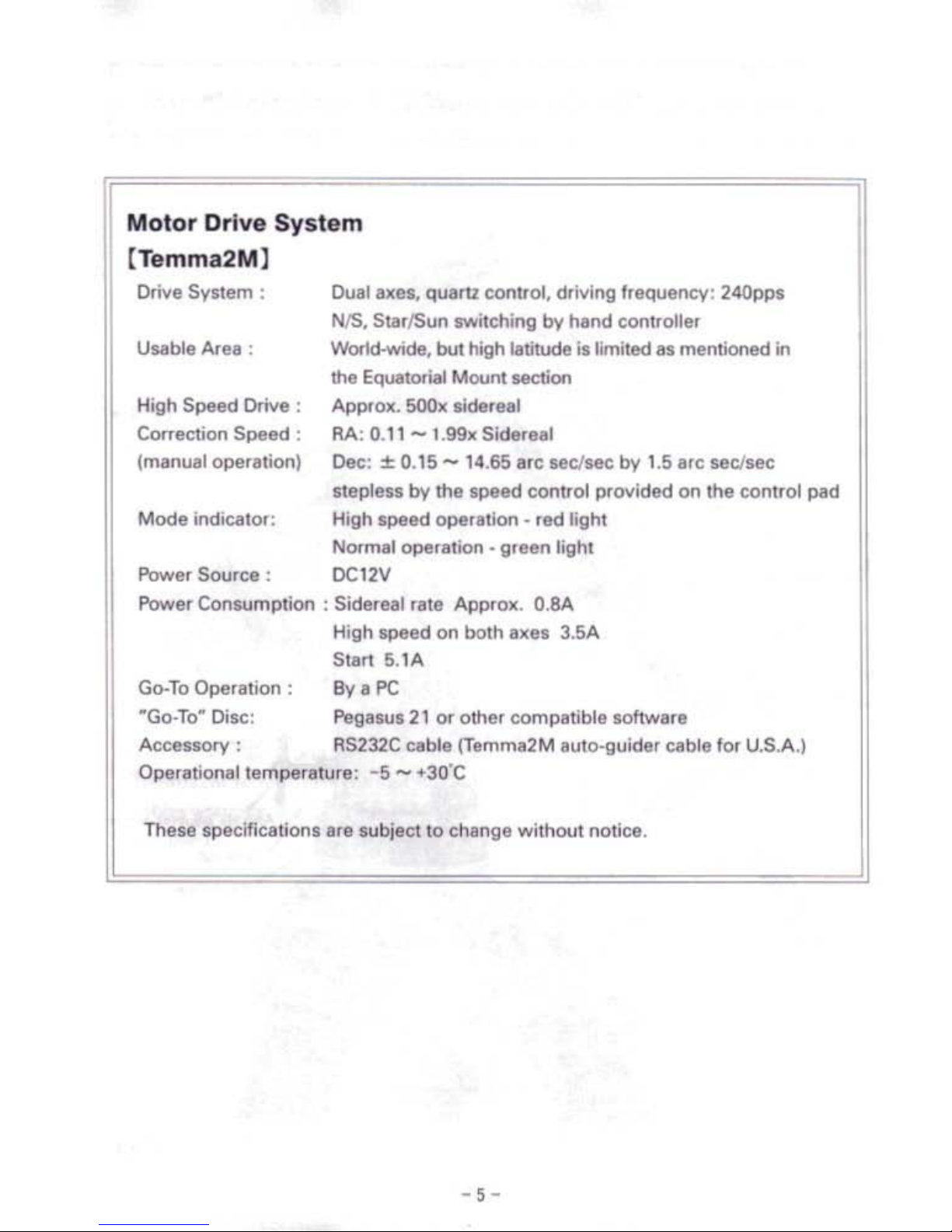
Motor
Drive
System
[Temma2M)
Drive System:
Dual
axes, quart2 control, driving frequency: 240pps
NIS,
SllIrlSun twitching
by
hand controller
Usable Area: World-wide, but high latitude is l.."ited
as
mentioned
in
tOe
Equatorial Moont section
High Speed Drive :
ApprolO:.
SOOlO:
siderlal
Correction Speed:
RA:
0.11 -1.99lO:
Sidereal
(manual operalion)
Dec:
± 0.15 -
14.65
arc seclsec by
1.5
arc sec/see
stepless
by
the speed control provided on the control pad
Mode
indic~llo,:
High speed
~ralion
-
led
light
Normal
~rlltion
• green lighl
Power Source:
DC12V
Power Consumplion : Sidereal rate Approx.
O.SA
High speed on both axes 3.5A
Stal1
5.1A
Go-To
Operation:
By a PC
"Go-To~
Disc:
F'egasus21
or other compatible software
Accessory:
RS232C
cable {Tamma2M auto-guider
CIIble
lor U.S.A.)
Operationallemperllture:
-5 -+30'C
These
specifications are $ubjeet
to
change without notice.
-
5-
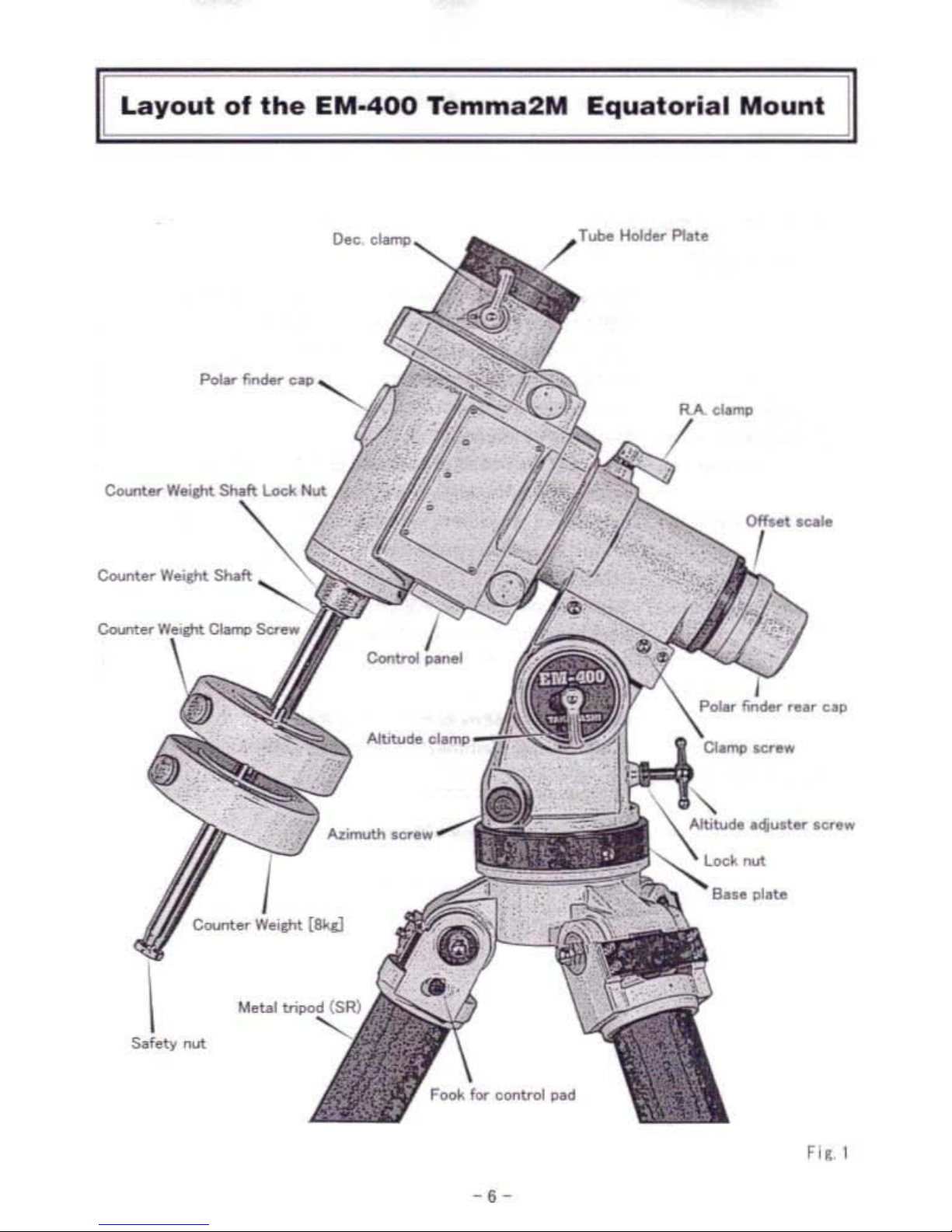
Layout
of
the
EM·400
Temma2M
Equatorial
Mount
Sefety
nut
/ T
....
Hold..-
Plot.
Fir, I
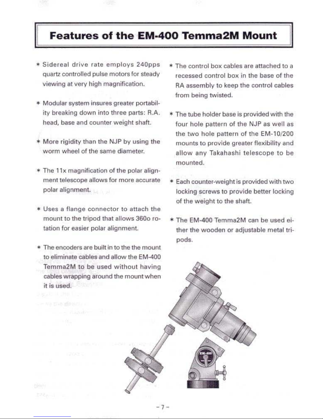
Features
of
the
EM·400
Temma2M
Mount
II
II
- 1 -
..
Sidereal
drive
rate
employs
24Qpps
quarU controlled pulse motors lor
steady
viewing al very high magnification.
..
Modular
system insures greater
portabil·
ity breaking down into three parts:
A.A,
head, base and
counter
weight
shaft.
..
More
rigidity
than
the
NJP
by
using
the
worm
wheel
of
the same diameter.
.. The 1b magnification
of
the polar align-
ment
telescope allows
for
more
accurate
polar
alignment.
..
Uses II
flange
connector
to
iI\l8ch
the
mount
to the tripod
that
allows 3600 ro-
tation fOi easier
polar
alignment.
...
The
encoders
are built in
to
the the
mount
to eliminate
cables
lind allow the
EM400
Temma2M
10
be
used
without
having
cables
wrapping
around
the
mount
when
it is used.
...
The control
bolt
cables
i1,e
attached
to a
recessed
control box in the
base
of the
RA
assembly
to
keep
the
control
cables
from
being
twisted,
*The tube
holder
base is
provided
with
the
four
hole
pattern
of
the NJP as
well
as
the
two
hole
pattern
of
the
EM·10/200
mounts
to
provide
greater fleKibility and
allow
any
Takahashi
telescope
to
be
mounted
.
• Each counter-weight is
provided
with
two
locking
screws
to
provide
better
locking
of
the
weight
to
the shaft•
*The
EM·400
Temma2M
can be
used
ei-
ther
the
wooden
or
adjustable
metal
tri-
pods
.

II
Layout
of
the
Control
Panel
[I
•
Control
Panel
Powe!LEOI
:
When
the
power
switch is slide to
the
On
position
the LED turns on and the
mount
is
activilted.
P-Light
Control:
When
the
Power
Switch
is
turned
on, the
~'um;nalor
for
the
polar alignment telescope
system
is turned on.
The
brightness
of
lhe
illuminator
can
be
ehange
bv
carefully turning !he P-Ught
c0n-
trol slotted screw
very
carefully
with.
plas-
tic
screw drivel. Once the brightness is set,
the
set
screw
should be leh alone.
DC12v:
Connect
the
POWIK
cable supplied
wilh
the
mount
to
/I
power
supply 12vDC
by
an&Ch-
ing
the
red !lItigator clip
to
the
+ terminal
and tho black alligator clip
10
the . terminal.
This
mounl
operates
on 12v
DC
only.
Auto
Guider:
The
terminal is
used
to
connect
an
auto
guider
to
the mount. There
/lfl!
three cables
available with
the
following terminations:
RJ_14. 5T-4 lind ST-7.
Control
Box:
This is
the
connector
for
the
hand
control
ix»l. Before inserting
the
cable into the
con·
nector makll certain that
the
pins are aligned.
PC
This terminal is
connected
to the
computer
cable supplied the mount that terminates in
an
AS232 serial connector
lemma
2M
,_
80
TO
SYSTEM
-
o
0:
TAKAHASHI
_.-
..
-_
-
.....
..
00
Fil
2
FII
3
Note: Seriel to
USB
conn~tors
a'e
avail·
able for
computer
without serial ports.
(Caution]
•
Insert
the
power
c:or.lIIClOI
carefulv
into
the
DC 12...
rooept&C\e mailing certain
that
it
bot
lOmB out
to
supply a
fum
connection
for
the
powM.
• The blank connector is currently
nOI
used
and
is provided for future expansion.
. ,-
- -
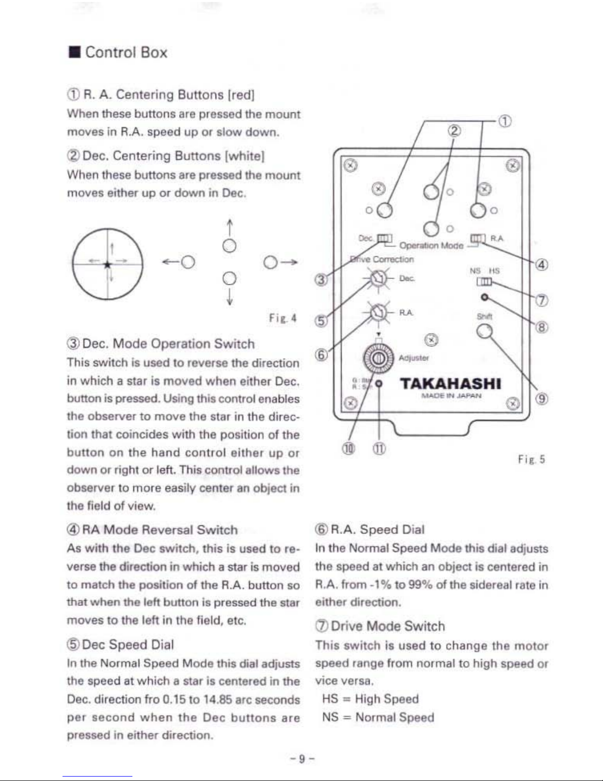
• Control Box
(D
R.
A.
Centering
Buttons
[red]
When these bullons ara prossed the mount
moves
in
R.A. speed up
0'
slow down.
<%>
Dec. Centering
Buttons
[whiteJ
Whon
these bullons are pressed the mount
movos either
up
Of
down
in
Dec.
I
/
,"
-0
o
\,.
~I
./
o
I
FiC
(
@Dec.
Mode
Operation
Switch
This switch
is
used to reverse the di,ection
in
which a star is moved when either Dec.
button
is
pressed. Using this control enables
the
observe'
to move tho flar
in
the direc-
tion that coincides with the position
of
the
bUllon on
the
hand control either
up
0'
down
Of
,ight
or
left.
This cont,oIallows
the
observer to more easily center an object
in
the
field
of
view.
@)AA
Mode
Reversal
Switch
AI
with the Dec switch, this is used
to
re-
verse the direction
in
which a star
is
moved
to
match the position
of
the R.A. bunon so
that when
the
left button
is
pressed the star
moves to the left
in
the field, etc.
@DecSpeed
Dial
In
the Normal
Speed
Mode this diat adjusts
the speed at which a star
i,
eente,ed
in
the
Dec.
direction fro 0.15 to 14.85 IfC seconds
par
second
when
the
Dec
buttons
are
pressed
in
eithe, direction.
(j)
<3)
<3)
0
0
0
u
~
••
~
u
<3)
<Q)
-
•
TAKAHASHI
•
<3)
_.-
<3)
@
~
@
Fic
5
(I)
R.A.
Speed
Dial
In
the Normal
Speed
Mode this di,tadjuS\s
the
speed
at which an object is centered
in
R.A. from
·1%
to
99%
of
the sidereal rate
in
either <!i'ection.
<Zl
Drive Mode
Switch
This switch is
used
to
change
the motor
speed
18nge
from
no,ma!
to
high
speed
or
vIce versa.
HS -High
Speed
NS
= Normal
Speed
-,-
 Loading...