

Page 1
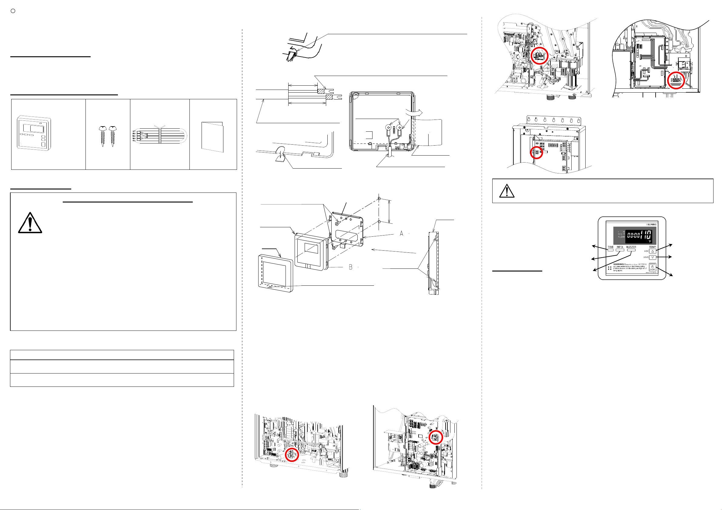
Model numbers
Attached short screws
Main unit
Frame
Cut out the partition using pliers.
1-3/8 Inch
1-5/8 Inch
Remote controller wiring
Plastic cover
Cut out
Remote controller wiring
Temperature Remote Controller: 9007603005 (TM-RE30)
Remote controller
cable*
fork terminals
[A] + [B]
520 Model (T-H2-DV/OS)
320 Model (T-H2S-DV/OS)
Metal plate
CAUTION
E
INSTALLATION INSTRUCTIONS
FOR YOUR SAFETY
For installer and owners safety, please read these instructions very
carefully before installation, and follow the instructions exactly. After
installation, please give this manual to the owner.
INCLUDED ACCESSORIES
Remote Controller Screws
Manual
*No cable is included in the optional TM-RE30.
H4.7”
W5.0”
D0.87”
Qty: 1 Qty: 2 Qty: 1 Qty: 1
INSTALLATION
• This remote controller is NOT waterproof.
Do not install in high-temperature environments, steamy
conditions (such as bathroom), outdoors, in direct
sunshine, and/or where children can reach. Make sure
CAUTION
<Water heaters and a multi-unit controller available for the
remote controller>
510 model (T-D2-IN/OS) / 520 model (T-H2-DV/OS) / 320 model (T -H2S-DV/OS)
710 model (T-M32) / 910 model (T-M50) / 9007675005 (TM-MC01)
<Remote Controller Wiring>
1. Take off the “Frame” from the remote controller by flat-blade screwdriver
etc. (Fig. A)
2. Attach the “Metal plate” [A] on the wall with two attached screws.
3. If you use another cable, crimp the “Fork terminals” to the wires.
4. Open the “Plastic cover”, and then attach the “Fork terminal” to the
connector base of the backside unit with two screws tight. (Cut out the
partition using pliers. Insert the wiring into the grooves and through the
partition.)
5. Close the” Plastic cover” and then hook the “Main unit” [B] to the
“Fixing bracket” on the “Metal plate” [A]. (Fig. C)
6. Attach the “Frame” back onto the remote.
the remote controller does not come into contact with
water or oil.
• Failure to follow precautions may cause malfunction or
failure.
• Do not place the remote control wiring close to other
• Do not extend the remote control wiring more than
• Use of a conduit is recommended to protect remote
wires from other products.
400 feet.
control wiring, minimum 20 AWG wire (No polarity).
(Fig. B)
Fig. A
Fig. B
Frame
Fig. C
Twist
Press flat-blade screwdriver against the cutout.
Then twist flat-blade screwdriver .
Frame
Use the
Remote controller
wiring inlet
which are att ached plastic sleeve.
Remote controller
Multi-unit controller
9007675005 (TM-MC01)
710 Model (T-M32)
910 Model (T-M50)
Make sure the remote wires and the remote terminals are not
shorted out, or the computer boards of the unit will be damaged.
3.3 Inch
Hook [B] to the Fixing
bracket on [A] surely.
<Connecting to the Water heater (or the Multi-unit controller)>
1. Turn off the 120VAC power supply to the unit (the water heater or the
multi-unit controller).
2. Take off t he front cover of the unit. T here are 3 or 4 screws on the front cover.
3. Locate the remote terminals on the heater’s computer board.
Reference Fig. D.
4. Slide the remote wires through the hole on the bottom of the unit's casing.
5. Connect the remote wires with the remote terminals in the unit properly.
(The terminals are not polarity sensitive.)
6. Place the front cover back on. Turn on the 120VAC power supply.
Fig. D
510 Model (T-D2-IN/OS)
<Exterior view of the remote controller>
OPERATION
"TIME"
"INFO"
"BUZZER"
<Set temperature>
1. Turn on the 120VAC power supply to the water heate r or the multi-unit controller.
2. Press the "ON/OFF" button on the remote to turn the remote controller on. It
shows the time and set temperature on the display as shown in Fig. E.
3. a) For 510 model (T-D2-IN/OS)
Press the "HOT" button or the "COLD" button to set the temperature.
You can set the temperature from 100 °F (37 °C) to 122 °F (50 °C).
Increasing temperature from 122 °F (50 °C) to 140 °F (60 °C)
• Press the “HOT” button to set 122 °F (50 °C).
• Press and hold the “INFO” button and the “HOT” button for at least 3
seconds. The remote will emit a beep and change to 131 °F (55 °C).
• Press the “HOT” button to set up to 140 °F (60 °C).
Increasing temperature above 140 °F (60 °C)
• Press the “HOT” button to set 140°F (60°C).
• Press and hold the “INFO” button and the “HOT” button for at least 3
seconds. The remote will emit a beep and change to 158 °F (70 °C) or 149 °F
(65 °C) – under the high temperature mode. (Refer to next page.)
• Press the “HOT” button to set up to 167 °F (75 °C) or 176 °F (80 °C) –
under the high temperature mode. (Refer to next page.) .
b) For 520 model (T -H2-DV/OS) / 320 m odel (T -H2S-DV/OS) / 710 model (T-M32) /
910 model (T -M50), and multi-unit controller 9007675005 (TM-MC01)
Press the "HOT" button or the "COLD" button to set the temperature.
You can set the temperature from 100 °F (38 °C) to 120 °F (50 °C).
(Continued overleaf)
Fig. E
"HOT"
"COLD"
"ON/OFF"
Page 2
<Set temperature> (continued)
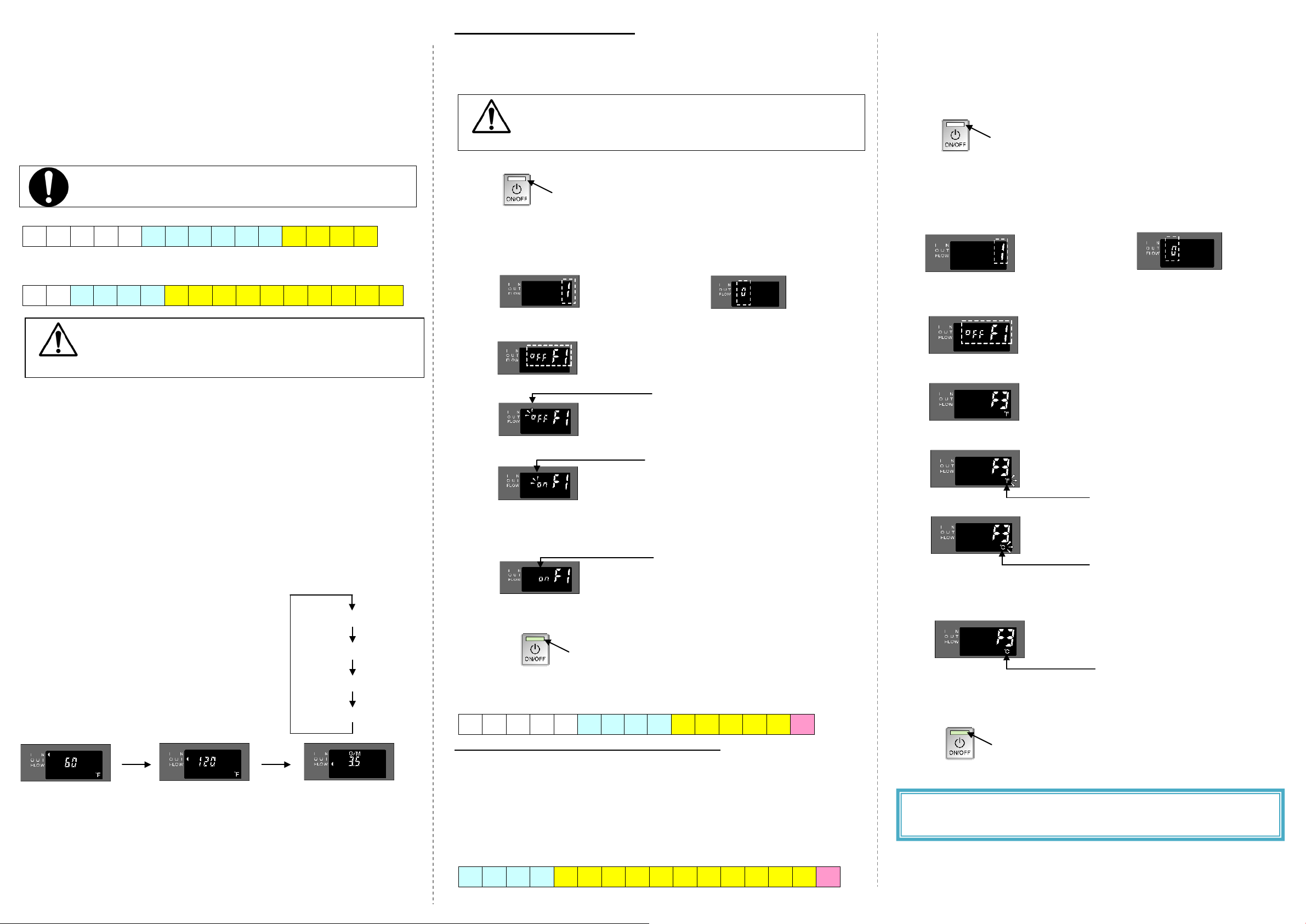
“ON” blinks
33V100-3
“0” is displa yed for Easy-Link / Multi-Unit Systems
Inlet water temperature
Water flow
Inlet water temperature
Outlet water temperature
Water flow
Temperature settings from the remote controller differ with the
Increasing temperature from 120 °F (50 °C) to 140 °F (60 °C)
• Press the “HOT” button to set 120 °F (50 °C).
• Press and hold the “INFO” button and the “HOT” button for at least 3
seconds. Th e remote will emit a beep and change to 125 °F (52 °C).
• Press the “HOT” button to set up to 140 °F (60 °C).
Increasing temperature above 140 °F (60 °C)
• Press the “HOT” button to set 140 °F (60 °C).
• Press and hold the “INFO” button and the “HOT” button for at least 3
seconds. The remote will emit a beep and change to 145 °F (63 °C).
• Press the “HOT” button to set up to 175 °F (80 °C) or 185 °F (85 °C) –
under the high temperature mode. (Refer to the right portion.)
water heater models. See t he tables below.
a) For 510 model (T-D2-IN/OS)
100 102 104 106 108 110 111 113 115 117 122 131 140 158 167
(Unit: °F)
b) For 520, 320, 710 and 910, models
(T-H2-DV/OS, T-H2S-DV/OS, T-M32, and T -M50)
100 105 110 115 120 125 130 135 140 145 150 155 160 165 170 175
(Unit: °F)
Temperature above 125 °F (52 °C) can cause severe burns
or death from scalding. Children, disabled and the elderly
CAUTION
are at high risk of being injured.
<Set the time>
1. Press the "TIME" button, then press the "HOT" or t he "COLD" button t o set
the clock time.
2. Press the "TIME" button again to save and exit.
NOTE: If you want to hide the clock time, press and hold the "TIME" button for
3 seconds or longer.
<Buzzer operation and Error code>
If there is a problem with the unit, the remote controller will sound a buzzer and
display the error code to inform you the source of the problem.
You can stop the buzzer by pressing the "BUZZER" button.
error code, refer to the water heater’s Installation Manual.
NOTE:
If you want to disable the buzzer operation, press and hold the
"BUZZER" button for 3 seconds or longer.
For details on the
<Information mode>
You can get some information about the water
heater condition by pressing the "INFO" butt on.
During the information mode, the information will be
rotated by pressing the "INFO" button as the
example to the right shows:
Outlet water temperature
Finish information mode
Display example:
<Energy saving mode >
The remote controller has an energy saving mode. The backlight of the LCD in
ADDITIONAL FEATURE S
<High Temperature mode>
To change the remote controller’s mode from Default Temperature Mode to
High Temperature Mode, please follow the procedures below:
DO NOT set temperature above 180°F if you use your
water heater in a recirculation system. This will cause
CAUTION
damage to the heater and void the warranty.
1. Turn of f power to the remote controller by pressing the “ON/OFF” button.
Lamp is OFF to indicate that power is off
2. Simultaneously press and hold both the “HOT” and “COLD” buttons for
at least 5 seconds. And then make sure “1” (or “0”) is displayed on
remote controller.
“1” is displayed for single unit.
“0” is displa yed for Easy-Link / Multi-Unit Systems
3.
Press the “TIME” button. Make sure “OFF” and “F1” are displayed on
remote controller.
4.
Press the “INFO” button. After, make sure “OFF” blinks.
“OFF” blinks
5.
Press the “HOT” button or the “COLD” button to set display to “on”.
6. Simultaneously press both the “BUZZER” button and the “INFO” button
to fix the setting.
7.
Make sure display is no longer blinking.
8.
Press the “ON/OFF” button to finish the setting.
Not blinking
9. Turn on p ower to the remote controller by pressing the “ON/OFF” button
again.
Lamp is ON to indicate that power is on.
<Temperatures available under the High Temperature Mode>
a) For 510 model (T-D2-IN/OS)
100 102 104 106 108 110 111 113 122 131 140 149 158 167
*The maximum set temperature with the remote controller
The remote shows “H” on the display at the maximum set temperature, which
represents 176 °F.
(Unit: °F)
H *
<Unit conversion mode>
The remote controller has a function that can change units of temperature
and flow rate from “°F and GPM” to “°C and Liter / min”, please follow the
procedures below:
1.
Turn of f power to the remote controller by pressing the “ON/OFF” button.
2. Simultaneously press and hold both the “HOT” and “COLD” buttons for
at least 5 seconds. And then make sure “1” (or “0”) is displayed on
remote controller.
“1” is displayed for single unit.
3.
Press the “TIME” button. Make sure “OFF” and “F1” are displayed on
remote controller.
4.
Press the “HOT” button or the “COLD” button to set display to “F3”.
5.
Press the “INFO” button. After, make sure “°F” blinks.
6.
Press the “HOT” button or the “COLD” button to set display to “°C”.
7. Simultaneously press both the “BUZZER” button and the “INFO” button
to fix the setting.
8.
Make sure display is no longer blinking.
9.
Press the “ON/OFF” button to finish the setting.
10. Turn on power to the remote controller by pressing the “ON/OFF”
button again.
If you have any questions, please call or write to the manufacturer
listed on the rating plate of your water heater.
Lamp is OFF to indicate that power is off
“°F” blinks
“°C” blinks
Not blinking
Lamp is ON to indicate that power is on.
the remote controller will be turned off in five minutes after the water he ater
stops the operation for energy saving. Once the unit is working, the backlight
of the LCD is turned back on during the operation
.
b) For 520, 320, 710, and 910 models
(T-H2-DV/OS, T-H2S-DV/OS, T -M32, and T -M50)
110 115 120 125 130 135 140 145 150 155 160 165 170 175 180 185
(Unit: °F)
 Loading...