

U
P
C
®
Mobius T-M50
Description/Application
Designed specifically for heavy-duty commercial applications. Fully modulating, gas-fired, tankless, on-demand water heater
with sealed combustion (optional) and power-vented flue. Can be installed either indoors or outdoors.
Supplies hot water to: domestic hot water systems (directly or indirectly using water storage tanks), recirculations systems,
hydronic heating systems, radiant floor heating systems, and/or combined domestic & heating applications, etc.
Local codes indictate proper compliance. Please check with all local codes prior to installation.
Fuel: NG or LP
Safety Features
•
Built in Freeze Protection
•
Manual Reset Hi Limit (Set at 194°F)
•
Overheat Cut Off Fuse
•
Inlet, Outlet & Thermistors for Constant Temperature
Monitoring
•
Air-Fuel Ratio Rod
•
GFI, Fuse & Surge Absorber
•
Flame Sensor
Venting and Combustion
•
5” Category III Stainless Steel
•
Vertical or Horizontal Installation
•
50’ Max Length, 5 elbows max
(90° elbows = 5’ equivalent length)
•
Power Vent
•
Electronic Ignition
•
5” Combustion Air Intake (with optional kit)
•
56 dB Noise Level at Max Output
Accessories
TM-MC01 Multi-Unit Controller (Multi-Unit System)
TM-RE30 Temperature Remote Control (optional)
- 400’ Max Distance From Water Heater
- Non-Polarized 18 Gauge Control Wiring
TM-DV50 Direct Vent Conversion Kit (optional)
TM-PC50 Pipe Cover (optional)
TM-VC50 Vent Cap (optional)
TM-BF50 Backflow Preventer (optional)
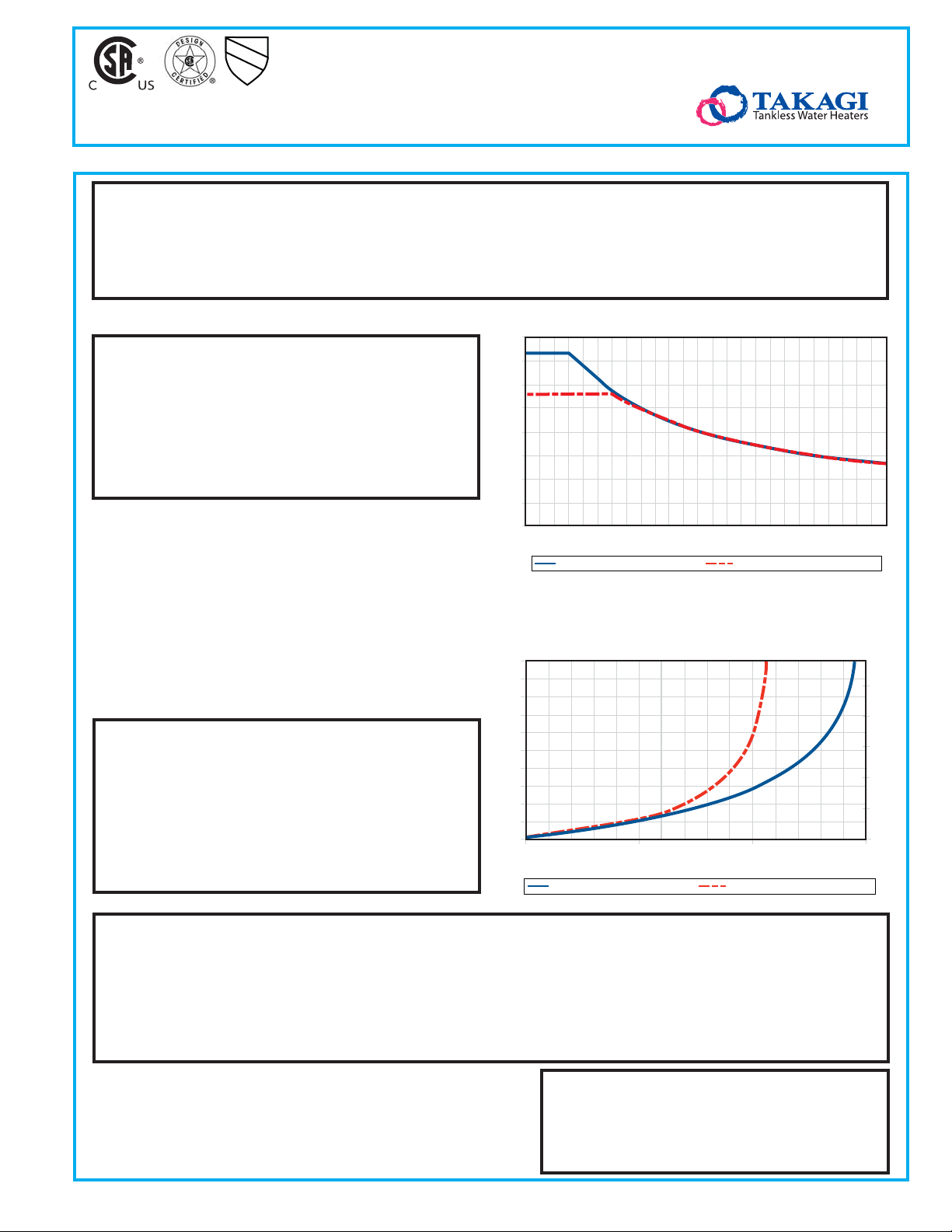
T-M50 Flow Rate Vs. Temperature Rise
16
14
12
10
8
6
Flow Rate (gpm)
4
2
0
25
25
20
15
10
Pressure Loss (psi)
5
0
0.0
45 65 85
Set temperature of 145° or lower Set temperature of 150° or higher
Above shown rate is based on single unit only
Set temperature of 145° or lower Set temperature of 150° or higher
105
Temperature Rise (°F)
T-M50 Pressure Loss
5.0
Flow Rate (gpm)
10.0
125 145
15.0
50
40
30
20
10
0
Head Feet
°
Temperature Settings
Dip Switch: 100°F 115°F 120°F (default) 135°F 145°F 155°F 165°F 185°F
TM-RE30 Remote Controller
Default Mode: 100°F
155°F
High Temp Mode: 110°F 115°F
165°F
105°F 110°F 115°F 120°F (default) 125°F 130° 135°F 140°F 145°F 150°F
160°F 165°F 170°F 175°F
120°F (default) 125°F 130°F 135°F 140°F 145°F 150°F 155°F 160°F
170°F 175°F 180°F 185°F
Takagi Industrial Co. USA, Inc.
5 Whatney Irvine, CA 92618
888.882.5244 www.takagi.com
12-023-2009
U
P
C
®
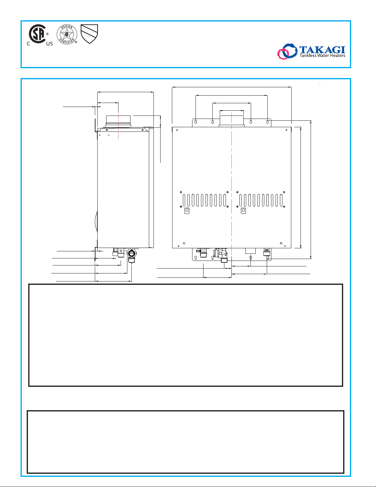
Mobius T-M50
1/2" (11.9mm)
1/2" (12.5mm)
4-3/8" (110.8mm) GAS
5
-3/8" (137.3mm) HOT
6-3/4" (171.3mm) 120V
7-5/8" (194.3mm) COLD
12-1/4" (311.5mm)
4-7/8" (122.9mm)
2-1/2" (62.1mm)
1-5/8" (40mm) COLD
5-7/8" (150mm) HOT
24-7/8" (632.9mm)
15" (381mm)
8" (203mm)
5" (127mm)
25-1/4" (642mm)
4" (100mm) 120V
7-3/8" (186mm)GAS
28-7/8" (734mm)
HT W D WT Volt Amp Flue Intake Connections
T-M
50
:
(Hot/Cold/Gas)
25.3” 24.8” 11.8” 112 lbs. 120 1.48 5” O.D.* 5” O.D. (opt.) 1” NPT
Input
Input
Max BTU/h Min BTU/h Thermal Eff. Min Press Max. Press
NG
LP
380,000 15,000 80.2% 5.0” W.C. 10.5” W.C.
380,000 15,000 82.4% 8.0” W.C. 14.0” W.C.
GPM Water PSI Coil Cap
0.5 - 14.5** 15 - 150 PSI*** ≈0.32 Gallons
Clearances Top Bottom Front Back Sides
Indoor 12” 12“ 24” 0.5“ 2”
Outdoor 36“ 12” 24“ 0.5” 2”
* Category III Required **Current numbers based on factory testing, 0.4 GPM Required for Continuous Fire After initial Ignition.
***Pressure Only Relief Valve Requires (Min. 380,000 BTUs. 150 PSI). Min 40 PSI or above recommended for maximum ow.
Takagi USA reserves the right to change or disconnue the design, drawing and/or specificaon of its products without noce at anyme.
Specication
Mobius water heater(s) shall be Model T-M50 as manufactured by Takagi Industrial Company, Inc. The Mobius water heater(s) shall be a copper coil
integral n and tube construction with quick release brass or bronze waterways. Heater(s) will be factory assembled and tested.
The heater shall be vented with 5” Stainless steel Category III vent pipe a distance not to exceed 50’ (equivalent) feet terminating vertically or horizontially
as prescribed. Intake air with optional direct vent kit may be of such material as PVC not to exceed a total of 50’ (equivalent).
The heater(s) shall be controlled by onboard solid state printed circuit board monitoring incoming and outgoing temperatures with factory installed
thermistors, sensing and controlling ow rate to set point temperature with control both air and gas mixture inputs to maintain thermal combustion
eciency. Unit also consists of ground fault interrupter, inline fusing, spark ignition and sensor system, aluminized stainless steel burners, air-fuel ration
rod, Hi limit switch, modulating and proportional gas valves, freeze protection sensor and heating block and overhead cut-o fuses.
The water heater(s) shall be CSA listed, exceeds the energy eciency requirements of ASHRAE 90. 1b-1992 and listed by SCAQMD rule 11 46.2 Low NOx.
06-021-2010
 Loading...