


TANKLESS
PRODUCT GUIDE
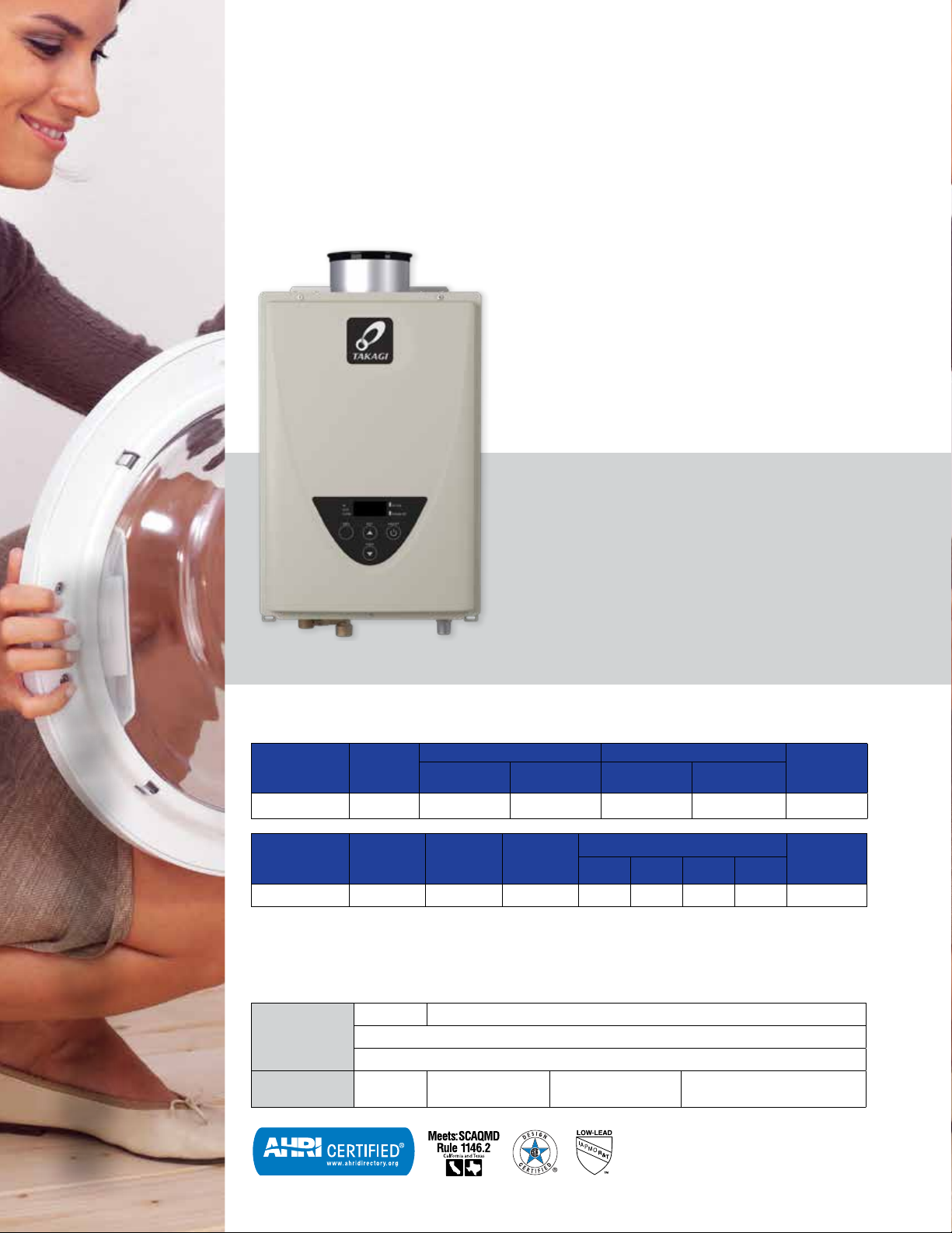
SAVE
ENERGY.
Energy-efficient, plentiful, and
endless supply of hot water.
Takagi has delivered innovative hot water solutions for
more than 70 years, and is sold exclusively by plumbing
wholesalers and contractors. Takagi’s selection of residential
and commercial tankless water heaters are unmatched for
SAVE
SPACE.
Compact size and wall-mounted to
free up valuable floor space.
SAVE
MONEY.
The smart choice that will save you a
substantial amount of energy.
1
quality and diversity. Anywhere hot water is needed, Takagi
provides an energy-efficient solution with long-lasting value
for years after installation. Takagi stands behind its products
and customeras with world-class service, combining cutting-
edge technology with committed people who take pride in
being the very best.
TANKLESS ADVANTAGE
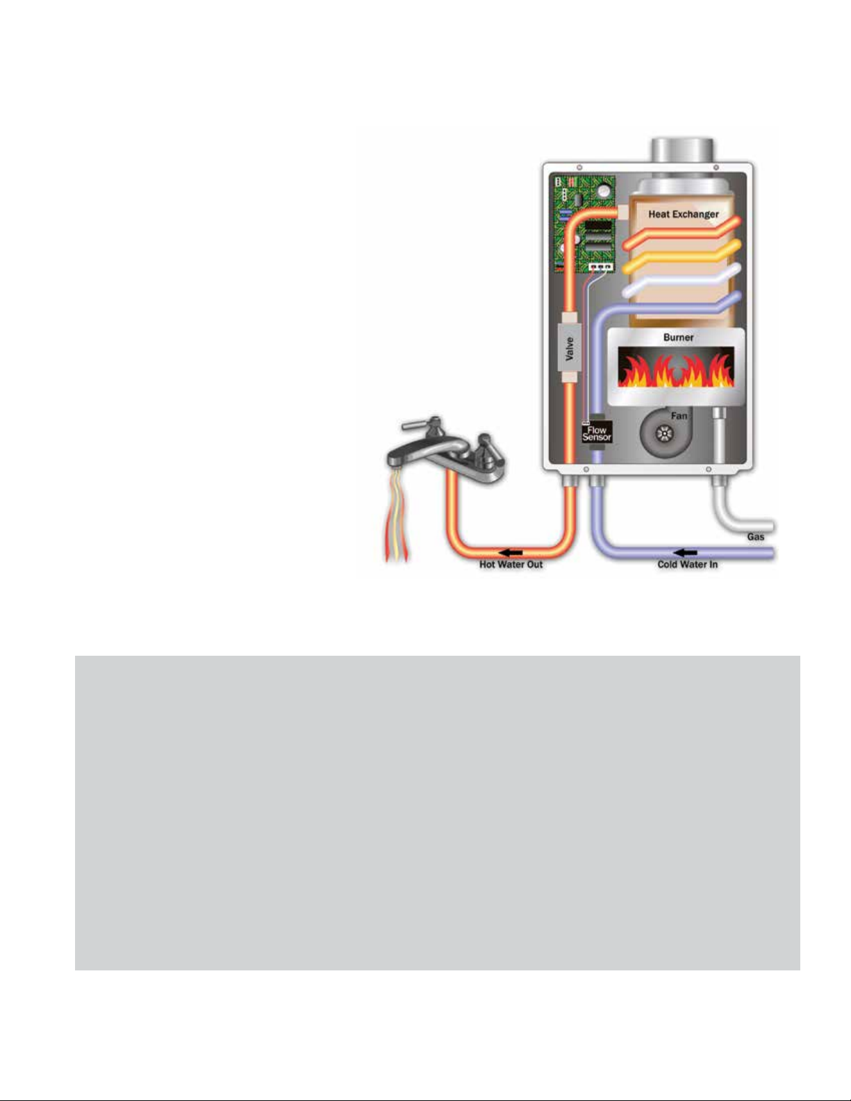
HOW IT WORKS – THE PROCESS:
• A hot water tap is opened.
• The opened tap allows water to flow
through the water heater. An internal
water flow sensor detects this flow.
• Upon flow detection, the flow sensor
sends the activation signal to the
computer board.
• The computer automatically ignites the
burner.
• As water flows through the heat
exchanger, it absorbs heat from the
burner.
• By the time the water exits the heater,
it has reached the designated set
temperature.
• When the hot water tap is closed, the
water heater automatically turns off.
ENDLESS
HOT WATER
Heating water only as it’s being used
means you will never run out of hot
water again. After the few seconds
it takes for the water to reach the
designated set temperature, our
water heaters will continually provide
a steady flow of hot water for as
long as your application needs it.
*Takagi tankless water heaters provide endless hot
water when sized appropriately for your home’s
needs.
ENERGY
CONSERVATION
Provides you with continuous hot water
in one of the most energy-efficient
ways possible. Conventional tank-type
water heaters will heat and store a set
volume of water, regardless of whether
someone is using that hot water or not.
Because our tankless water heaters
only activate when hot water is being
used, no standby energy losses are
incurred, providing efficient heating
while conserving energy.
COMPACT
SIZE
On top of all this, an Takagi tankless
water heater takes up much less space
than your conventional tank-type water
heater or boiler. Takagi’s wall-mount
design offers flexible installations
freeing up valuable storage space.
2
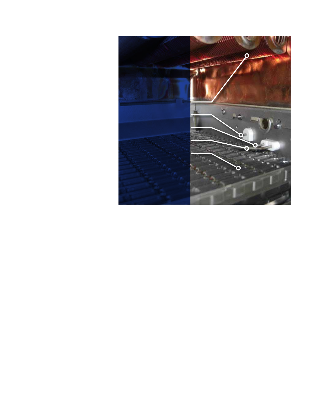
SAFETY
At Takagi, we place the safety and
reliability of our products above all else.
By incorporating technologically advanced
safety features into every model, we
provide the assurance and peace of mind
that can only come from an Takagi quality
product.
Air-Fuel Ratio (AFR)
Sensor
Takagi’s unique AFR sensor monitors and
maintains proper combustion at all times.
Together with the onboard computer, this
system will adjust the fan motor speed to
ensure that air and fuel have a proper
mixture ratio, minimizing emissions and
maximizing efficiency.
Additional Safety
Features
Freeze Protection:
Every heater in Takagi’s tankless lineup has
an internal freeze protection system, which
is rated to protect the heaters when installed
in sub-freezing conditions. This system
works to keep water temperatures within the
heat exchanger from falling below a certain
level, preventing freeze damage.
Hi-Limit Switch:
HEAT EXCHANGER
IGNITER
AFR
FLAME SENSOR
BURNER
Ensures that water temperatures do not exceed safe levels. Before the water temperature can even reach these unsafe levels,
the hi-limit switch activates by disengaging the gas valves, effectively shutting down the water heater.
PVC Venting:
Indoor condensing models have a thermistor and hi-limit switch that monitor the exhaust temperature. If the exhaust
temperature nears an unsafe limit, these features regulate combustion and can shut the heater down to protect the integrity of
the PVC vent material.
Overheat Cutoff Fuse:
Ensures that there are no breaches in the heat exchanger drum. In cases where enough physical damage might have been
done to the water heater to lead to a breach in the heat exchanger drum, the overheat cutoff fuse reacts by shutting down the
water heater if the surface of the heat exchanger retains too much heat.
3

0.016" (0.4mm)
0.020" (0.5mm)
water
water
drum coil
drum coil
drum
25% Thicker
DURABILITY
0.020" (0.5mm)
HEAT EXCHANGER WITH COMMERCIAL-GRADE COPPER
Only Takagi incorporates true commercial-grade heat exchangers in our tankless heaters (D2, 510U/C, or 510U, 510C,
H3, 540P, CT-199 and M50 non-ASME models). All aspects of the heat exchanger are designed to add the durability and
reliability that is vital to any successful commercial organization or business.
Commercial-Grade Copper Alloy
Our commercial-grade copper is a heat-resistant copper alloy, with additive elements that make it much stronger and harder
than the standard C1220 copper used in most other heat exchangers. Our commercial-grade copper has 8 times the tensile
strength of regular copper. Even at high temperatures, our commercial-grade copper maintains a fine grain and high strength.
Commercial-grade copper provides resistance to the damaging effects of erosion that can cause heat exchangers to leak.
Commercial-Grade Copper Tubing
Drum Thickness
During every ignition cycle, thermal expansion causes all heat exchangers to undergo heat stress. After the thousands of ON/
OFF cycles typically seen in a commercial application, this heat stress can prove damaging. This is why the heat exchangers
in our commercial and light commercial products utilize drums that are 25% thicker, ensuring the longevity of our products. A
thicker drum creates less strain on the heat exchanger.
A thinner drum strains more
under heat stress
drum
water
drum coil
water
drum coil
A thicker drum creates less
strain on the heat exchanger
water
drum coil
water
25% Thicker
drum coil
drum
4
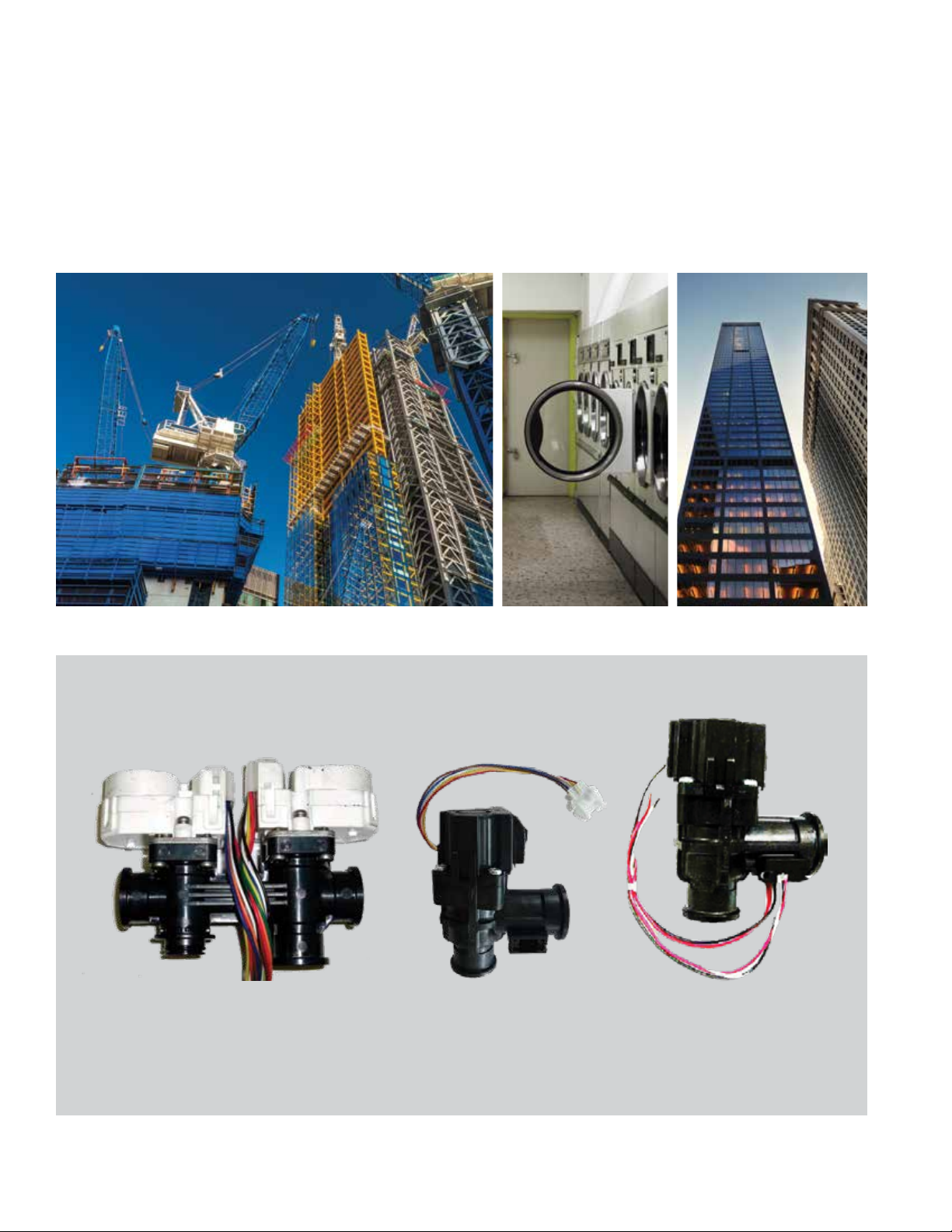
WATER VALVES
Making true commercial-grade water heaters involves more than just redesigning our heat exchangers—every internal component
has to measure up to Takagi’s commercial standards. Just like our advanced heat exchangers, the longevity and functionality of
components such as our water valves and flow sensors are also of great importance.
Our commercial-grade water heaters (D2, 510U/C, 510C, and T-H3), as well as our commercial water heaters (CT-199
and T-M50) feature a bypass and flow adjustment valve, which not only provide the optimal control and precision essential for
commercial usage, but also offer the durability needed to handle tough, high-volume conditions.
Stepper Motor Water Valves -
M50 Models
5
Bypass Valve - D2/510U/510C,
CT-199 and H3 Models
Flow Adjustment - D2/510U/510C
CT-199 and H3 Models
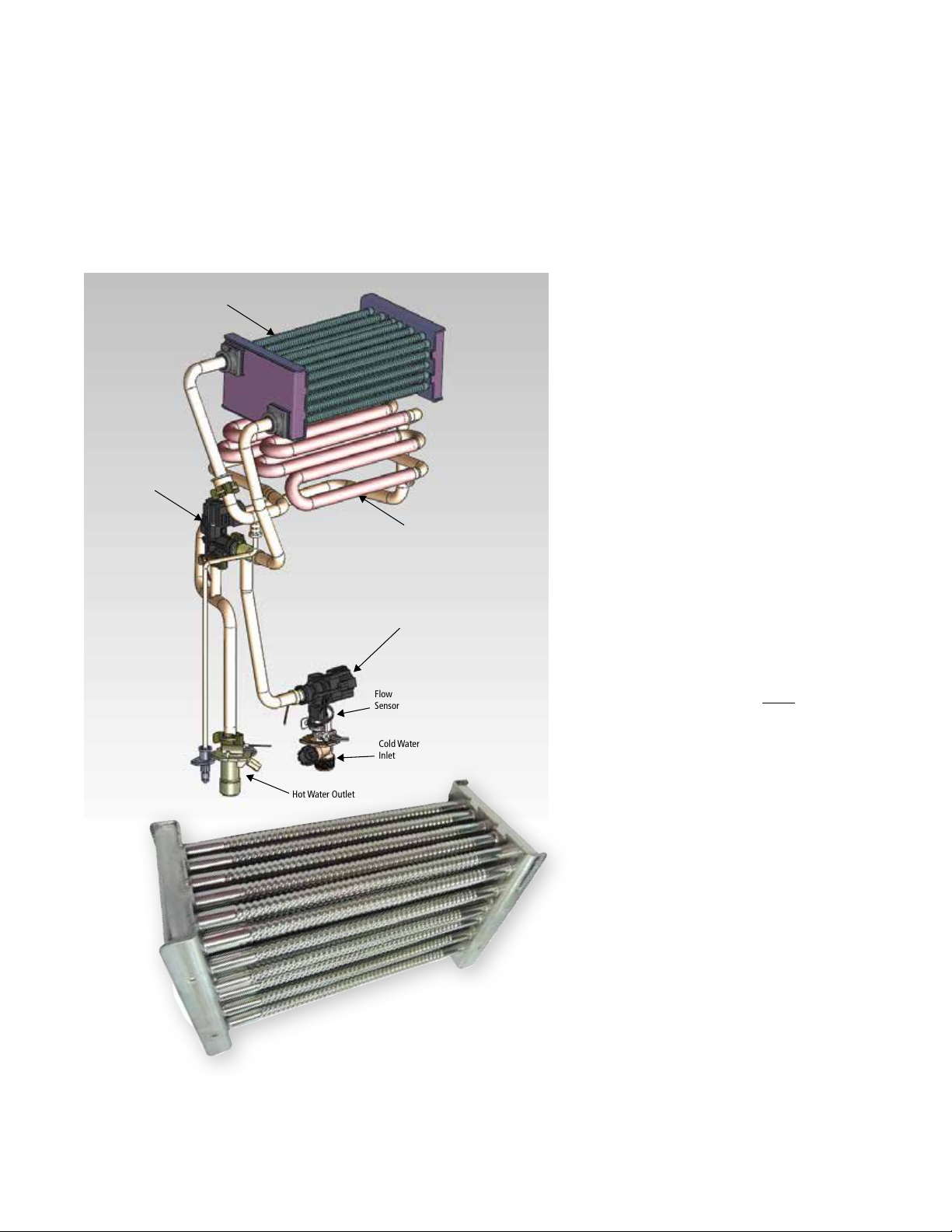
SECONDARY HEAT EXCHANGER 316L STAINLESS STEEL
(CONDENSING MODELS ONLY)
The secondary condensing heat exchanger is made of high-quality 316L stainless steel. This is where the rest of the heat
transfer occurs. Due to the lower temperature acidic condensation occurs, and stainless steel is required in order to avoid
corrosion.
For condensing heat exchangers, it is more suitable to use 316L stainless steel because of the extreme environment (heat,
acidic condensation, chloride) that the material is subjected to.
Secondary HX-Stainless Steel 316L
Bypass Valve
Hot Water Outlet
Flow
Sensor
Cold Water
Inlet
Primary HX
Commerical-Grade
Copper
Drum
Coil
Flow Adjustment
Valve
PRIMARY HEAT
EXCHANGER:
COPPER VS.
STAINLESS STEEL
• Heat transfers 25 times more readily
through copper than stainless steel.
Consequently, for the same amount
of heat transfer, stainless steel heat
exchangers need to be larger than
copper heat exchangers, leading to a
larger pressure loss.
• At higher temperatures, it is the nature
of stainless steel to become prone
to a number of problems not usually
experienced at room temperature. It is
vulnerable to pitting corrosion and stress
corrosion cracking (SCC).
• Stainless steel is NOT better for
durability because it is harder.
Hardness causes the material to
become brittle. Stainless steel will
crack after numerous cycles of
thermal expansion/contraction,
especially with chloride in the
water. Copper heat exchangers
are less brittle and better suited
for expansion/contraction without
cracking.
• In a
dual
heat exchanger design,
corrosion is not a big concern in
the non-condensing primary heat
exchanger because no condensation
forms on the exterior of the pipes.
Stainless steel is unnecessary for this
stage.
Note: H3M, H3J and H3S condensing line units use C1220
copper and do not have a bypass valve
* Diagram represents H3
6

WATER FLOW
Condensation can build up over time in any heat
exchanger, causing damage and premature leaks.
Takagi’s commercial models (M50 series) include
condensation reduction features that safeguard
against these types of damaging effects.
Better Water Pathway
Design
By redesigning and redirecting the flow of water,
the temperature of the heat exchanger drum and
finned coils stay elevated above dew point,
making it much more difficult for condensation to
build.
Fin Pitch
By widening the pitch of the heat exchanger fins,
not only do we improve durability by reducing
occurrences of blockage, we also maintain higher
temperatures on the upper finned coils. Keeping
these coils at elevated temperatures reduces the
likelihood of condensation buildup.
FIN
Finned Coil
90%-95% of total
heat absorbed)
Drum Coil
(5%-10%
of total heat
absorbed)
Hot Water Outlet
(100% heat absorbed)
No condensation
buildup on
drum coil
Burner
M
Bypass Valve
(M50)
Flow
Sensor
Cold Water Inlet
7
BASIC SIZING GUIDELINES
The flow rate capacity of tankless water heaters depends on
the temperature difference between the desired output and
incoming water temperature. The flow rate comparison chart
and table shown here summarize the flow rate charts found in
the specifications of each model.
Takagi water heaters are sized according to the peak flow
rate requirements, worst-case temperature-rise scenarios,
and types of applications. Once these factors have been
determined, refer to either the flow rate comparison here or
Application designers/engineers can decide whether
to size for full flow, expected flow, or utilize probability
models such as the modified “Hunter Curve.” For large
scale applications such as hotels, apartment complexes
and large restaurants, Hunter Curves are commonly used
to estimate the peak flow rate demand when given the
total amount of fixture units within an application. It is up
to the application designer/engineer to determine the
amount of fixture units within any given application.
the flow rate charts found in each model’s specifications.
Select the appropriate water heater as well as the amount of
water heaters required.
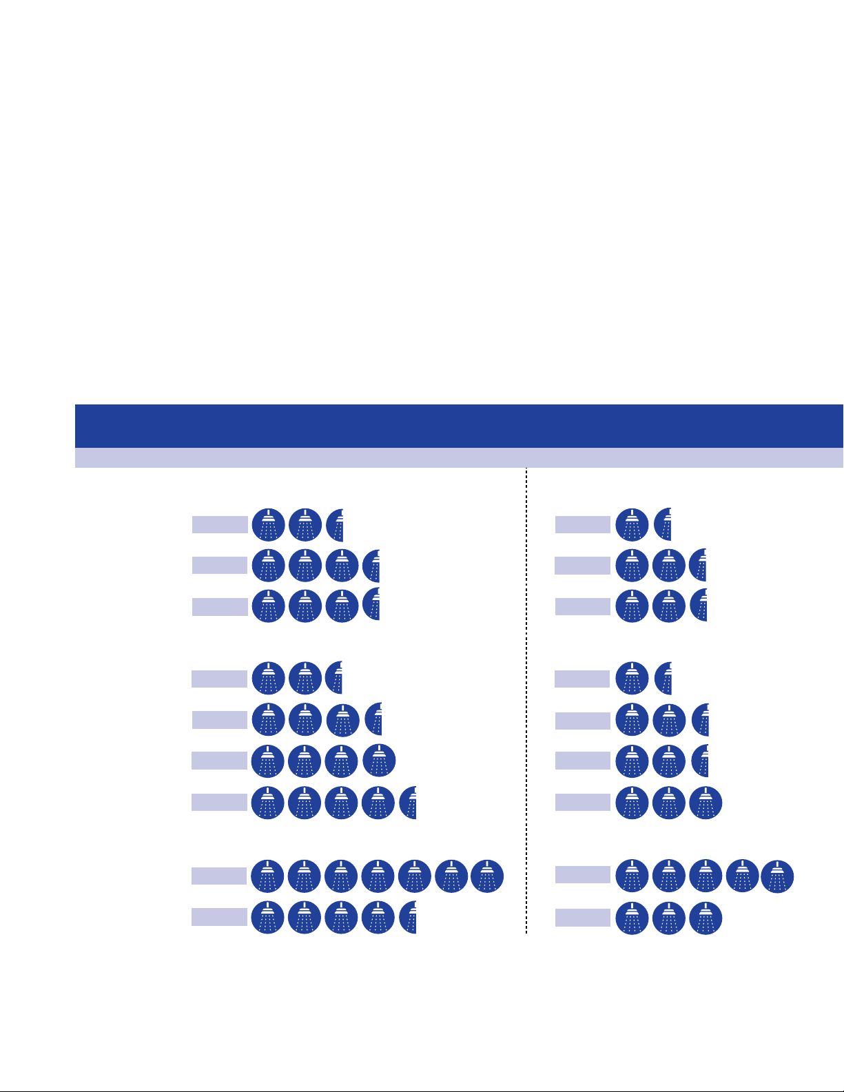
MATCH THE UNIT TO YOUR NEEDS
Warmer Climates
70°F Incoming Groundwater Temperature
Capacity - Number of Shower Heads
Non-Condensing Units
(Assuming the set point temperature is 120˚F )
Cooler Climates
50°F Incoming Groundwater Temperature
KJr2/110U/110C
K4/310U/310C
D2/510U/510C
Condensing Units
H3M
H3J
H3S
H3/540P
Commercial Units
M50
CT-199
2.5 Showers
3.5 Showers
3.5 Showers
2.5 Showers
3.5 Showers
4 Showers
4.5 Showers
7 Showers
4.5 Showers
1.5 Showers
2.5 Showers
2.5 Showers
1.5 Showers
2.5 Showers
2.5 Showers
3 Showers
5 Showers
3 Showers
8
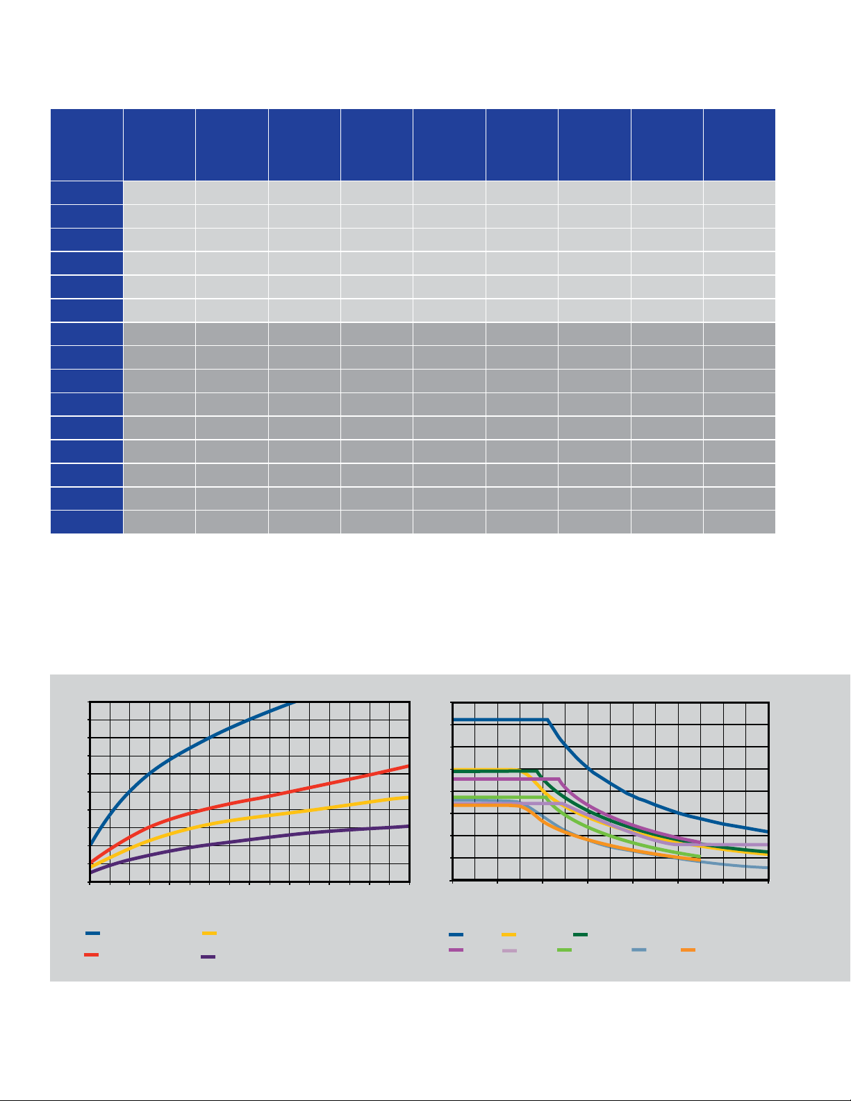
FLOW RATE GUIDE
Temperature Rise vs. Gallons per Minute
Temp
Rise
30°
35°
40°
45°
50°
55°
60°
65°
70°
75°
80°
85°
90°
95°
100°
KJr2/
110U/
110C
K4/
310U/
310C
D2/
510U/
510C
H3M H3J H3S H3/540P CT-199 M50
6.6 8.0 10.0 6.6 6.6 8.0 10.0 10.0 14.5
6.6 8.0 9.3 6.4 6.6 8.0 10.0 10.0 14.5
5.7 7.8 8.1 5.6 6.6 8.0 9.5 9.5 14.5
5.1 6.9 7.2 5.0 6.6 7.6 8.4 8.4 13.5
4.6 6.2 6.5 4.5 6.1 6.8 7.6 7.6 12.2
4.2 5.7 5.9 4.1 5.5 6.2 6.9 6.9 11.1
3.8 5.2 5.4 3.7 5.1 5.7 6.3 6.3 10.1
3.5 4.8 5.0 3.4 4.7 5.3 5.8 5.8 9.4
3.3 4.4 4.7 3.2 4.3 4.9 5.4 5.4 8.7
3.1 4.1 4.3 3.0 4.1 4.6 5.0 5.0 8.1
2.9 3.9 4.1 2.8 3.8 4.3 4.7 4.7 7.6
2.7 3.7 3.8 2.6 3.6 4.0 4.4 4.4 7.2
2.5 3.5 3.6 2.5 3.4 3.8 4.2 4.2 6.8
2.4 3.3 3.4 2.3 3.2 3.6 4.0 4.0 6.4
2.3 3.1 3.3 2.2 3.0 3.4 3.8 3.8 6.1
Flow rate is determined by temperature rise. To determine your temperature rise, subtract the incoming water temperature from
the set output temperature. All units are factory set to 120°F or 122°F but can be changed.
Example of Hunter Curves for
Sizing Large Applications
100
90
80
70
60
50
40
30
Gallons Per Minute
20
10
0
0
Restaurants
Hospitals, Nursing Homes,
Dormitories, Hotels & Motels
75
25
50
125
150
175
225 325
200
Fixture Units
Apartments & Houses
Office Buildings & Schools
250
275
300
375
400
350100
Comparison of Flow Rates vs.
Temperature Rise
16
14
12
Flow Rate (gpm)
10
8
6
4
2
0
M50 D2/510U/510C H3/540P and CT-199
H3S K4/310U/310C
H3J
H3M
Temperature Rise (°F)
140120100806040200
KJr2/110U/110C
9

SIMPLE TANKLESS SIZING
TANKLESS MODELS
GROUND WATER TEMPERATURE
FACTO R
The temperature of incoming ground water
(cold water inlet temperature) varies greatly
throughout the U.S. and also fluctuates
with the changing of the seasons. The
temperature of water as it enters the
water heater will determine the amount of
“temperature rise” required to achieve the
desired hot water outlet temperature (120°F
is recommended).
The best way to measure incoming ground
water temperature is to use a thermometer
to measure cold water temperature during
the coldest season of the year. To simplify
the process, use this map to determine
whether your installation location is in the
Southern Zone, Central Zone or Northern
Zone.
PEAK HOT WATER DEMAND
The next step is to determine how many
gallons per minute of hot water will be
required during the busiest usage period
(peak demand). Consider all appliances
and fixtures that use hot water, including
lavatory faucets, kitchen faucets, washing
machines, dishwashers, showers and
bathtubs. Be sure to determine how many
appliances and fixtures will be used at the
same time (peak demand).
Average Ground Water Temperature
Average Ground Water
Temperature: 62°F to 77°F
Average Ground Water
Temperature: 52°F to 61°F
NORTHERN ZONESOUTHERN ZONE CENTRAL ZONE
Average Ground Water
Temperature: 37°F to 51°F
Remember, these are general recommendations. Your Takagi Water Heater Specialist can review your family’s
needs in even greater detail to make sure the model you choose will always provide enough hot water to meet
the demand.
10
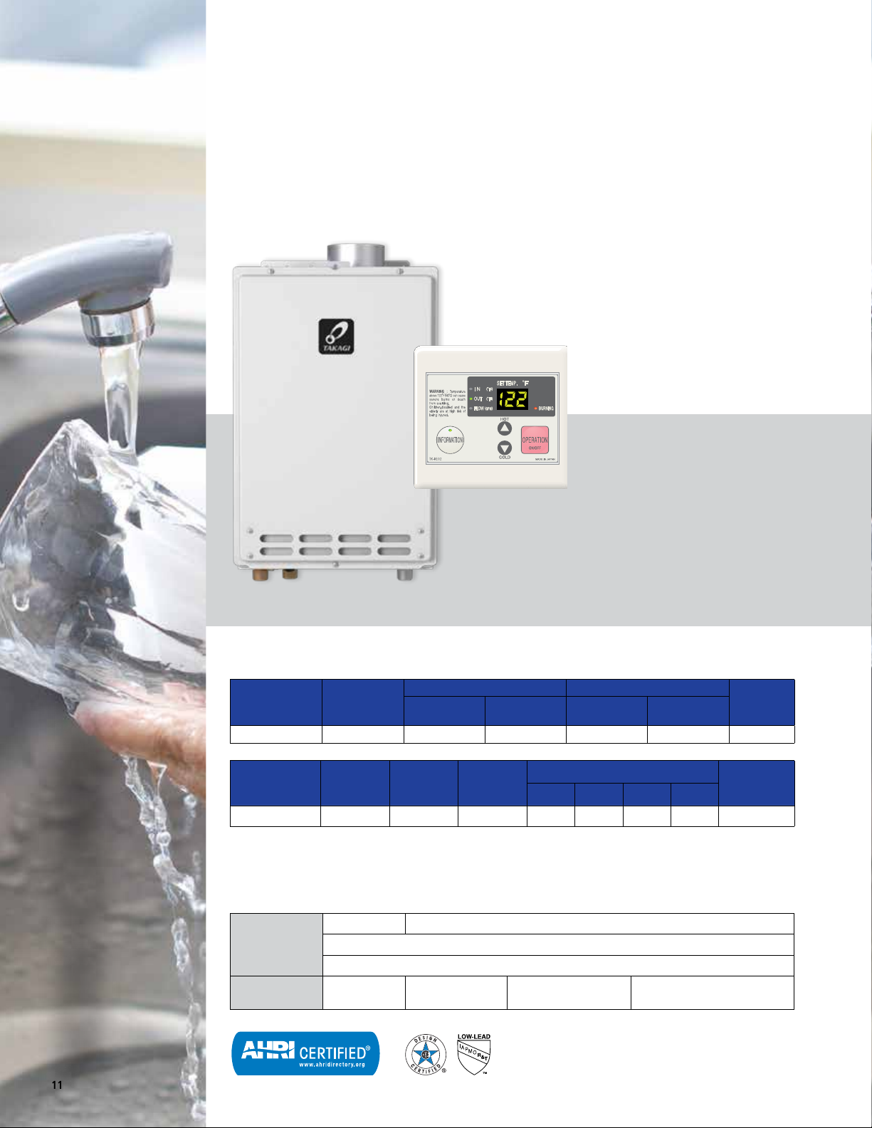
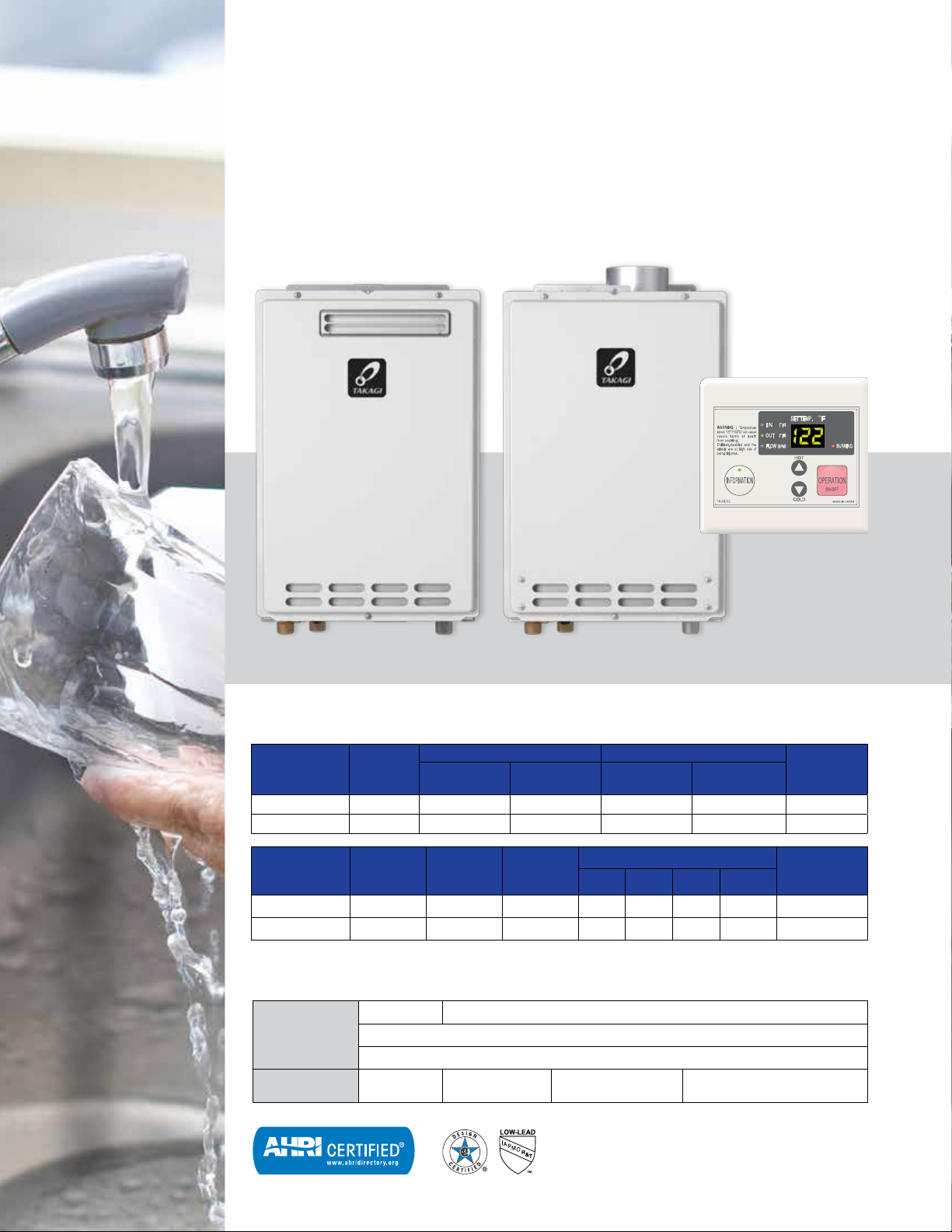
KJR2 SERIES
The KJr2 Series is great for apartments, one bath homes in cold climates, condos and
summer cabins. A remote control is included as a standard feature.
T-KJR2-IN
Specifications
Gas Consumption Input Inlet Gas Pressure**
Model Number* Type
T-KJr2-IN-N Natural 19,500 140,000 4.0 10.5 0.79
Model Number*
T-KJr2-IN-N 6.6 3/4" NPT 3/4" NPT 12 12 3 4 38
*For propane models, change “N” to “P”
**For propane models, minimum inlet gas pressure is 8.0 in. W.C. and maximum inlet gas pressure is 14.0 in. W.C.
KJr2
Temperature
Settings
Electric 120 V
Maximum
GPM
Dipswitches 113°F 122°F (default) 131°F 140°F
With 100112183 remote (max. distance 150’ from heater, non-polarized 20 gauge wiring.)
99°F to 167°F (16 options), 122°F Default Factory Setting
Minimum
(BTU/H)
Hot/Cold
Connections
73 W / 0.61 A
(Operation)
Maximum
(BTU/H)
Gas
Connection
Minimum
(in. W.C.)
Clearances (in.)
Top Bottom Side Front
6 W / 0.05 A
(Standby)
111 W / 0.93 A
(Freeze-Protection)
Maximum
(in. W.C.)
Approx
Shipping
Weight (lbs)
UEF
11
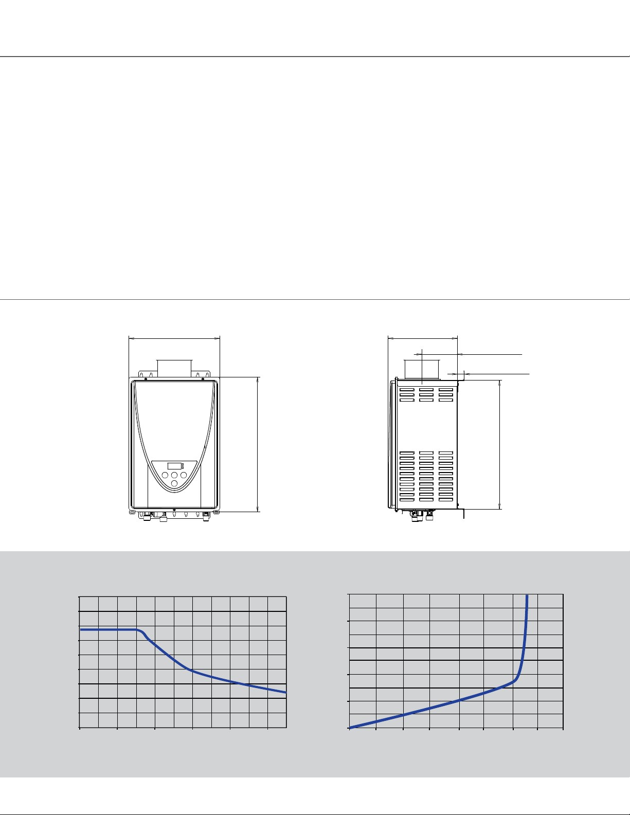
ANSI Z21.10.3 • CSA 4.3
NON-CONDENSING
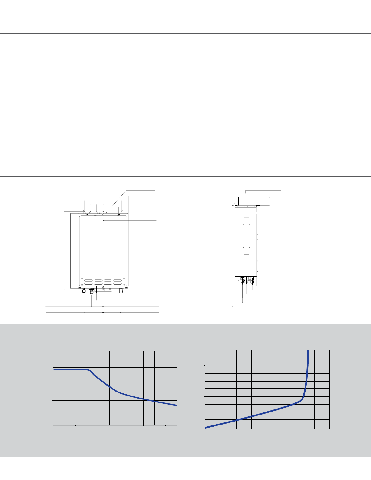
2-1/4" (56 mm) COLD
3-7/8" (98mm) GAS
4-7/8" (124mm) HOT
1" (26mm)
4" (102mm)
4-7/8" (123mm) 120V
7-3/4" (196mm)
2-1/4" (57mm)
Specifications
KJr2: Flow Rate vs. Temperature Rise
KJr2: Pressure Loss
Head (ft)
Indoor installation only
Power Vent or Power Direct Vent
Design
Low NOx Emissions
4” Category III Vent
Flow Rate up to 6.6 GPM
• Values based on factory testing. 0.4 GPM required
for continuous fire after initial ignition
Dimensions
13-3/4" (350mm)
10" (254mm)
4" (101 mm)
1-3/4" (45mm)1-3/4" (45mm)
2-1/4" (56mm)
Water Pressure: 15-150 psi
• Pressure Only Relief Valve Requires (Min 140,000 btu/h,
150 psi).
• 40 psi or above recommended for max. flow
Warranty
• 15-year limited warranty on heat exchanger in residential
applications.
• 5-year limited warranty on heat exchanger in commercial
applications.
• 5-year warranty on all parts.
• Refer to takagi.com for further warranty details
4" (102mm)
21-3/8" (544mm)
1-7/8" (47mm)
COLD 3-1/8" (79mm)
HOT 5-1/4" (133mm)
KJr2: Flow Rate vs. Temperature Rise
9.0
8.0
7.0
6.0
5.0
4.0
Flow rate (gpm)
3.0
2.0
1.0
0
Temperature rise (°F)
10 30
20-1/4" (520mm)
120V 1-3/8" (36mm)
GAS 4-7/8" (124mm)
50
70 90 110
100806040200.0
KJr2: Pressure Loss
50
45
40
35
30
25
20
Pressure Loss (psi)
15
10
5
0
Flow Rate (gpm)
2-1/4" (57mm)
1" (26mm)
2-1/4" (56 mm) COLD
3-7/8" (98mm) GAS
4-7/8" (123mm) 120V
4-7/8" (124mm) HOT
7-3/4" (196mm)
120
110
100
90
80
70
60
50
Head (ft)
40
30
20
10
0
8.06.0402.00.0
12
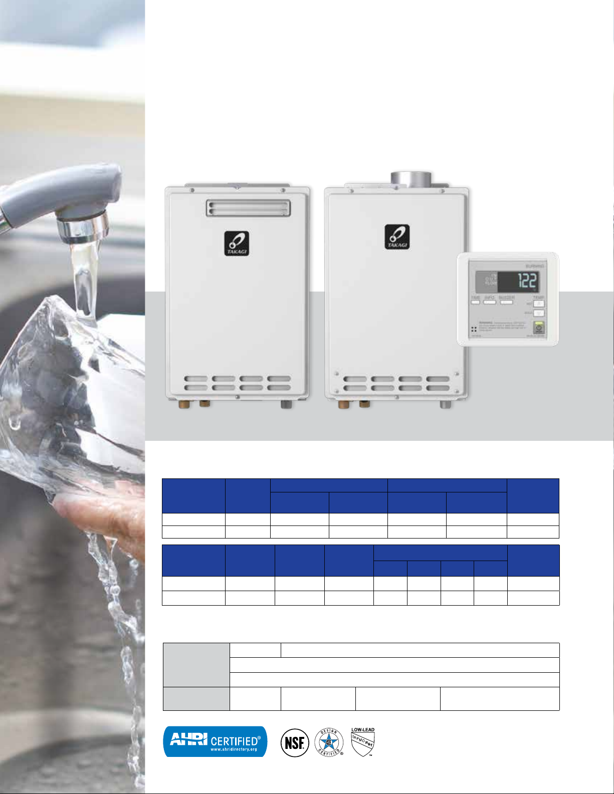
K4 SERIES
The K4 features a max flow rate of 8.0 gpm, providing enough hot water for a home with
up to three showers at the same time. A remote control is included as a standard feature.
T-K4-OS
T-K4-IN
Specifications
Gas Consumption Input Inlet Gas Pressure**
Model Number* Type
T-K4-IN-N Natural 11,000 190,000 4.0 10.5 0.80
T-K4-OS-N Natural 11,000 190,000 4.0 10.5 0.80
Model Number*
T-K4-IN-N 8 3/4" NPT 3/4” NPT 12 12 3 4 43
T-K4-OS-N 8 3/4" NPT 3/4” NPT 36 12 3 24 43
*For propane models, change “N” to “P”
**For propane models, minimum inlet gas pressure is 8.0 in. W.C. and maximum inlet gas pressure is 14.0 in. W.C.
K4
Temperature
Settings
Electric 120 V
Maximum
GPM
Dipswitches 113°F 122°F (default) 131°F 140°F
With 100112183 remote (max. distance 150’ from heater, non-polarized 20 gauge wiring.)
99°F to 167°F (16 options), 122°F Default Factory Setting
Minimum
(BTU/H)
Hot/Cold
Connections
88 W / 0.73 A
(Operation)
Maximum
(BTU/H)
Gas
Connection
6 W / 0.05 A
(Standby)
Minimum
(in. W.C.)
Clearances (in.)
Top Bottom Side Front
Maximum
(in. W.C.)
111 W / 0.93 A
(Freeze-Protection)
Approx
Shipping
Weight (lbs)
UEF
13
ANSI Z21.10.3 • CSA 4.3
NON-CONDENSING

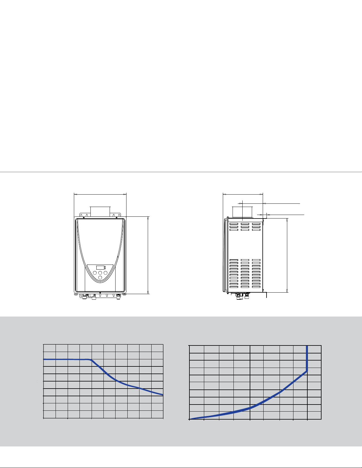
Specifications
HOT
COLD 3-1/4" (84mm)
1-5/8" (43mm)
9-1/2" (241mm)
K4: Pressure Loss
Head (ft)
K4: Flow Rate vs. Temperature Rise
Indoor and Outdoor Installation Options
Power Vent or Power Direct Vent Design
Low NOx Emissions
4” Category III Vent
Flow Rate up to 8.0 GPM
• Values based on factory testing. 0.4 GPM required for
continuous fire after initial ignition
Water Pressure: 15-150 psi
• Pressure Only Relief Valve Requires (Min 190,000 btu/h,
150 psi).
• 40 psi or above recommended for max. flow
Dimensions
13-3/4" (350mm)
10" (254mm)
1-3/4" (45mm) 1-3/4" (45mm)
4" (101 mm)
1-3/8" (36mm)
Warranty
• 15-year limited warranty on heat exchanger in residential
applications.
• 5-year limited warranty on heat exchanger in commercial
applications.
• 5-year warranty on all parts.
• Refer to takagi.com for further warranty details
4-3/8" (113mm)
K4: Flow Rate vs. Temperature Rise
9.0
8.0
7.0
6.0
5.0
4.0
3.0
Flow rate (gpm)
2.0
1.0
0
10
Temperature rise (°F)
21-3/8" (544mm)
20-1/4" (520mm)
1-7/8" (47mm)
5-1/4" (133mm)
30
120V 1-3/8" (36mm)
GAS 4-7/8" (124mm)
50 70 90 110
100806040200.0
K4: Pressure Loss
50
45
40
35
30
25
20
Pressure Loss (psi)
15
10
5
0
1.0 3.0 5.0 7.0 9.0
Flow Rate (gpm)
1" (26mm)
COLD 2-7/8" (71mm)
120VAC 3-7/8" (99mm)
GAS 5-1/4" (135mm)
HOT 6-1/2" (164mm)
19-3/8" (493mm)
120
110
100
90
80
70
60
50
40
Head (ft)
30
20
10
8.06.0402.00.0
0
14
D2 SERIES
The D2 series is well suited for residential/commercial applications such as small restaurants
and beauty salons. Utilizing commercial grade copper alloy for the heat exchanger tubing, the
D2 series is also suitable for heavier residential usages such as combination space heating and
domestic recirculation systems. A remote control is included as a standard feature.
T-D2-INT-D2-OS
Specifications
Gas Consumption Input Inlet Gas Pressure**
Model Number* Type
T-D2-IN-N Natural 11,000 199,000 4.0 10.5 0.80
T-D2-OS-N Natural 11,000 199,000 4.0 10.5 0.80
Model Number*
T-D2-IN-N 10 3/4" NPT 3/4” NPT 12 12 3 4 45
T-D2-OS-N 10 3/4" NPT 3/4” NPT 36 12 3 24 45
*For propane models, change “N” to “P”
**For propane models, minimum inlet gas pressure is 8.0 in. W.C. and maximum inlet gas pressure is 14.0 in. W.C.
D2
Temperature
Settings
Electric 120 V 90 W / 0.75 A 6 W / 0.05 A
Maximum
GPM
Dipswitches 104°F 113°F 122°F (default) 140°F
With 100112155 remote (max. distance 400’ from heater, non-polarized 20 gauge wiring.)
100°F to 176°F (15 options), 122°F Default Factory Setting
Minimum
(BTU/H)
Hot/Cold
Connections
Maximum
(BTU/H)
Gas
Connection
Minimum
(in. W.C.)
Clearances (in.)
Top Bottom Side Front
Maximum
(in. W.C.)
111 W / 0.93 A
(Freeze-Protection)
Approx
Shipping
Weight (lbs)
UEF
15
ANSI Z21.10.3 • CSA 4.3
NON-CONDENSING
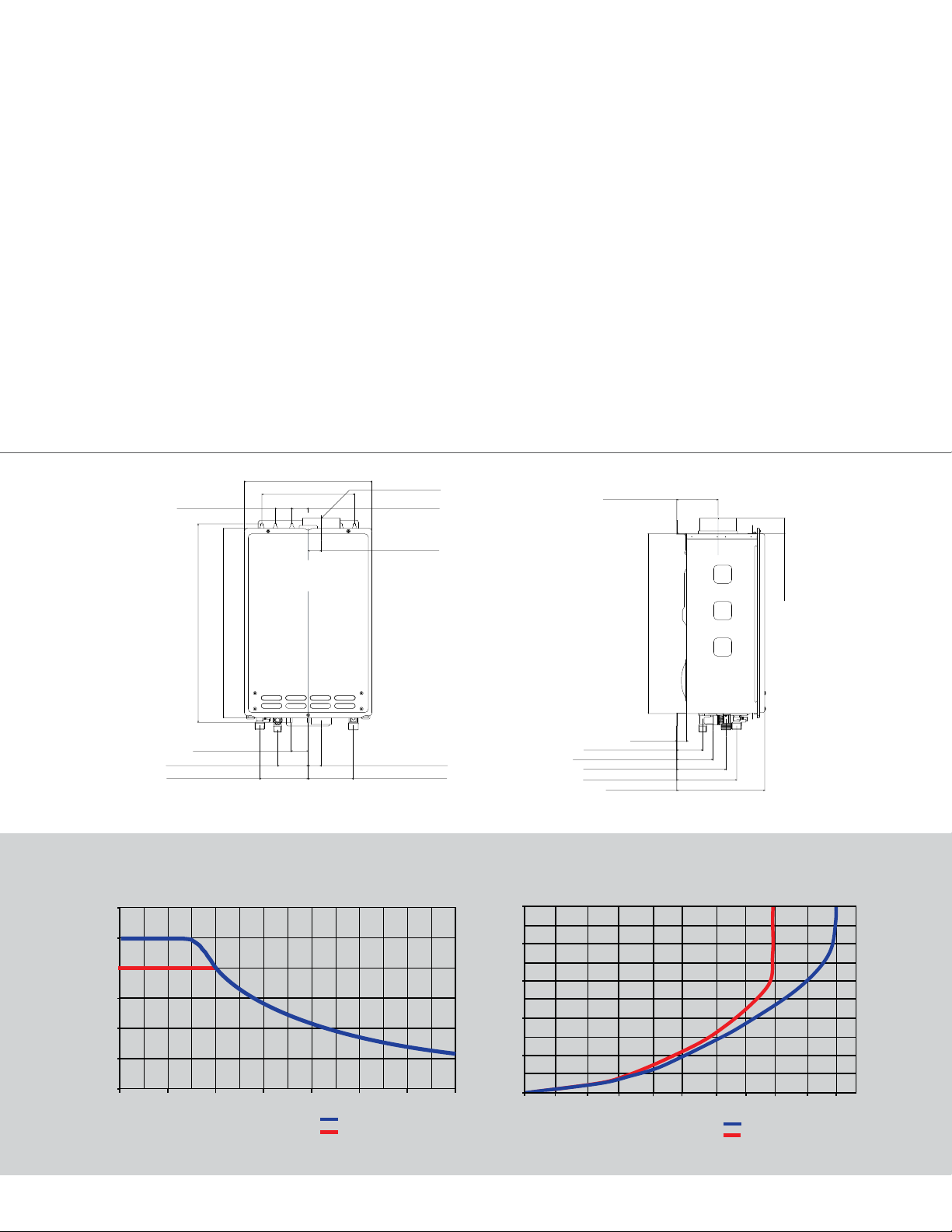
Specifications
D2: Pressure Loss
Head (ft)
HOT
COLD 3-1/4" (84mm)
1-5/8" (43mm)
9-1/2" (241mm)
D2: Flow Rate vs. Temperature Rise
Indoor and Outdoor Installation Options
Power Vent or Power Direct Vent Design
Low NOx Emissions
4” Category III Vent
Flow Rate up to 10.0 GPM
• Values based on factory testing. 0.4 GPM required for
continuous fire after initial ignition
Water Pressure: 15-150 psi
• Pressure Only Relief Valve Requires (Min 199,000 btu/h,
150 psi).
• 40 psi or above recommended for max. flow
Dimensions
13-3/4" (350mm)
10" (254mm)
1-3/4" (45mm) 1-3/4" (45mm)
4" (101 mm)
1-3/8" (36mm)
Easy-Link up to 4 heaters
Warranty
• 15-year limited warranty on heat exchanger in residential
applications.
• 5-year limited warranty on heat exchanger in commercial
applications.
• 5-year warranty on all parts.
• Refer to takagi.com for further warranty details
4-3/8" (113mm)
D2: Flow Rate vs. Temperature Rise
12
10
8
6
Flow rate (gpm)
4
2
0
Temperature rise (°F)
21-3/8" (544mm)
20-1/4" (520mm)
1-7/8" (47mm)
5-1/4" (133mm)
120V 1-3/8" (36mm)
GAS 4-7/8" (124mm)
Set temperature: 122°F or lower
Set temperature: 131°F or higher
19-3/8" (493mm)
1" (26mm)
COLD 2-7/8" (71mm)
120VAC 3-7/8" (99mm)
GAS 5-1/4" (135mm)
HOT 6-1/2" (164mm)
D2: Pressure Loss
50
45
40
35
30
25
20
Pressure Loss (psi)
15
10
5
140120100806040200
0
Flow Rate (gpm)
8.0 10.06.0402.00.0
Set temperature: 122°F or lower
Set temperature: 131°F or higher
120
110
100
90
80
70
60
50
40
30
20
10
Head (ft)
0
16

110C SERIES
The 110C Simplicity Series is fuel convertible out of the box and easily installs using contractor
preferred concentric venting. Great for apartments, one bath homes in cold climates, condos
and summer cabins.
TK-110C-NI
Specifications
Gas Consumption Input Inlet Gas Pressure**
Model Number* Type
TK-110C-NI Natural 15,000 140,000 4.0 10.5 0.81
Model Number*
TK-110C-NI 6.6 3/4" NPT 3/4” NPT 12 12 3 4 55
*Indoor models only. Units are field convertible from natural gas to propane with supplied conversion kit.
**For propane, minimum inlet gas pressure is 8.0 in. W.C. and maximum inlet gas pressure is 14.0 in. W.C.
110C
Temperature
Settings
Electric 120 V
Maximum
GPM
Dipswitches 120 °F (default) 140°F
With 100209924 remote (max. distance 400’ from heater, non-polarized 20 gauge wiring.)
100 °F to 140 °F (9 options), 120 °F Default Factory Setting
Minimum
(BTU/H)
Hot/Cold
Connections
53 W / 0.58 A
(Operation)
Maximum
(BTU/H)
Gas
Connection
Minimum (in.
W.C.)
Clearances (in.)
Top Bottom Side Front
2 W / 0.06 A
(Standby)
Maximum (in.
W.C.)
Approx
Shipping
Weight (lbs)
99 W / 0.83 A
(Freeze-Protection)
UEF
17
ANSI Z21.10.3 • CSA 4.3
NON-CONDENSING
Specifications
110C: Flow Rate vs. Temperature Rise
110C: Pressure Loss
Head (ft)
10-1/2” (266.5 mm)
5-7/16” (137.7 mm)
19-1/2” (495.7 mm)
1.0” (25.5 mm)
5-7/16” (137.7 mm)
Top view
Installations are simple and flexible with
contractor-preferred concentric venting
Long venting runs up to 43 feet and
operates in altitudes up to 10,100 feet
Gas convertible from natural gas to
propane using the included conversion kit
Flow Rate up to 6.6 GPM
• Values based on factory testing. 0.4 GPM required for
continuous fire after initial ignition
Meets Ultra-Low NOx requirements
Dimensions
13-3/4” (350 mm)
Water Pressure: 15-150 psi
• Pressure Only Relief Valve Requires (Min 140,000 btu/h,
150 psi)
• 40 psi or above recommended for max. flow
Warranty
• 15-year limited warranty on heat exchanger in residential
applications.
• 5-year limited warranty on heat exchanger in commercial
applications.
• 5-year warranty on all parts.
• Refer to takagi.com for further warranty details
10-1/2” (266.5 mm)
5-7/16” (137.7 mm)
1.0” (25.5 mm)
110C: Flow Rate vs. Temperature Rise
9.0
8.0
7.0
6.0
5.0
4.0
Flow rate (gpm)
3.0
2.0
1.0
0
10 30 50 70 90 110
Temperature rise (°F)
6040200.0
20-1/2” (520 mm)
80
100
110C: Pressure Loss
50
45
40
35
30
25
20
Pressure Loss (psi)
15
10
5
0
Flow Rate (gpm)
19-1/2” (495.7 mm)
8.06.0402.00.0
120
110
100
90
80
70
60
50
40
30
20
10
0
Head (ft)
18
310C SERIES
The 310C Simplicity Series is fuel convertible out of the box and easily installs using
contractor preferred concentric venting. It generates a max flow rate of 8.0 gpm, providing
enough hot water to run three showers at the same time.
TK-310C-NI
Specifications
Gas Consumption Input Inlet Gas Pressure**
Model Number* Type
TK-310C-NI Natural 15,000 190,000 4.0 10.5 0.82
Model Number*
TK-310C-NI 8 3/4" NPT 3/4” NPT 12 12 3 4 55
*Indoor models only. Units are field convertible from natural gas to propane with supplied conversion kit.
**For propane, minimum inlet gas pressure is 8.0 in. W.C. and maximum inlet gas pressure is 14.0 in. W.C.
310C
Temperature
Settings
Electric 120 V
Maximum
GPM
Dipswitches 120°F (default) 140°F
With 100209924 remote (max. distance 400’ from heater, non-polarized 20 gauge wiring.)
100 °F to 140 °F (9 options), 120°F Default Factory Setting
Minimum
(BTU/H)
Hot/Cold
Connections
71 W / 0.81 A
(Operation)
Maximum
(BTU/H)
Gas
Connection
2 W / 0.06 A
(Standby)
Minimum (in.
W.C.)
Clearances (in.)
Top Bottom Side Front
Maximum (in.
W.C.)
99 W / 0.83 A
(Freeze-Protection)
Approx
Shipping
Weight (lbs)
UEF
19
ANSI Z21.10.3 • CSA 4.3
NON-CONDENSING
Specifications
10-1/2” (266.5 mm)
5-7/16” (137.7 mm)
19-1/2” (495.7 mm)
1.0” (25.5 mm)
5-7/16” (137.7 mm)
Top view
310C: Pressure Loss
Head (ft)
310C: Flow Rate vs. Temperature Rise
10.0
Installations are simple and flexible with
contractor-preferred concentric venting
Long venting runs up to 43 feet and
operates in altitudes up to 10,100 feet
Gas convertible from natural gas to
propane using the included conversion kit
Flow Rate up to 8.0 GPM
• Values based on factory testing. 0.4 GPM required for
continuous fire after initial ignition.
Meets Ultra-Low NOx requirements
Dimensions
13-3/4” (350 mm)
Water Pressure: 15-150 psi
• Pressure Only Relief Valve Requires (Min 190,000 btu/h,
150 psi)
• 40 psi or above recommended for max. flow
Warranty
• 15-year limited warranty on heat exchanger in residential
applications.
• 5-year limited warranty on heat exchanger in commercial
applications.
• 5-year warranty on all parts.
• Refer to takagi.com for further warranty details
10-1/2” (266.5 mm)
5-7/16” (137.7 mm)
1.0” (25.5 mm)
310C: Flow Rate vs. Temperature Rise
9.0
8.0
7.0
6.0
5.0
4.0
Flow rate (gpm)
3.0
2.0
1.0
0
Temperature rise (°F)
20-1/2” (520 mm)
Pressure Loss (psi)
100806040200.0
310C: Pressure Loss
100
90
80
70
60
50
40
30
20
10
0
Flow Rate (gpm)
19-1/2” (495.7 mm)
8.06.0402.00.0
200
180
160
140
120
100
80
60
40
20
Head (ft)
0
20

510C SERIES
The 510C Simplicity Series is fuel convertible out of the box and easily installs using contractor
preferred concentric venting. It is well suited for residential/commercial applications such as
small restaurants and beauty salons. Utilizing commercial grade copper alloy for the heat
exchanger tubing, the 510C series is also suitable for heavier residential usages such as
combination space heating and domestic recirculation systems.
TK-510C-NI
Specifications
Gas Consumption Input Inlet Gas Pressure**
Model Number* Type
TK-510C-NI Natural 15,000 199,000 4.0 10.5 0.81
Model Number*
TK-510C-NI 10 3/4" NPT 3/4” NPT 12 12 3 4 55
*Indoor models only. Units are field convertible from natural gas to propane with supplied conversion kit.
**For propane, minimum inlet gas pressure is 8.0 in. W.C. and maximum inlet gas pressure is 14.0 in. W.C.
510C
Temperature
Settings
Electric 120 V
Maximum
GPM
Dipswitches 120°F (default) 140°F
With 100209924 remote (max. distance 400’ from heater, non-polarized 20 gauge wiring.)
100°F to 160°F (13 options), 120°F Default Factory Setting
Minimum
(BTU/H)
Hot/Cold
Connections
72 W / 0.85 A
(Operation)
Maximum
(BTU/H)
Gas
Connection
Minimum
(in. W.C.)
Clearances (in.)
Top Bottom Side Front
3 W / 0.07 A
(Standby)
100 W / 0.83 A
(Freeze-Protection)
Maximum
(in. W.C.)
Approx
Shipping
Weight (lbs)
UEF
21
ANSI Z21.10.3 • CSA 4.3
NON-CONDENSING

Specifications
510C: Flow Rate vs. Temperature Rise
10-1/2” (266.5 mm)
5-7/16” (137.7 mm)
19-1/2” (495.7 mm)
1.0” (25.5 mm)
5-7/16” (137.7 mm)
Top view
510C: Pressure Loss
Head (ft)
Installations are simple and flexible with
contractor-preferred concentric venting
Long venting runs up to 43 feet and
operates in altitudes up to 10,100 feet
Gas convertible from natural gas to
propane using the included conversion kit
Flow Rate up to 10 GPM
• Values based on factory testing. 0.4 GPM required for
continuous fire after initial ignition.
Meets Ultra-Low NOx requirements
Dimensions
13-3/4” (350 mm)
Water Pressure: 15-150 psi
• Pressure Only Relief Valve Requires (Min 199,000 btu/h,
150 psi)
• 40 psi or above recommended for max. flow
Easy-Link up to 4 heaters or connect up to
20 heaters with a Multi-Unit Controller
Warranty
• 15-year limited warranty on heat exchanger in residential
applications.
• 5-year limited warranty on heat exchanger in commercial
applications.
• 5-year warranty on all parts.
• Refer to takagi.com for further warranty details
10-1/2” (266.5 mm)
5-7/16” (137.7 mm)
1.0” (25.5 mm)
510C: Flow Rate vs. Temperature Rise
12
11
10
9
8
7
6
5
4
Flow rate (gpm)
3
2
1
0
Temperature rise (°F)
Set temperature: 125°F (52°C) or lower
Set temperature: 130°F (55°C) or higher
20-1/2” (520 mm)
140120100806040200
510C: Pressure Loss
100
90
80
70
60
50
40
Pressure Loss (psi)
30
20
10
0
Flow Rate (gpm)
19-1/2” (495.7 mm)
Set temperature: 125°F (52°C) or lower
Set temperature: 130°F (55°C) or higher
Set Temperature 125°F (52°C) or higher, maximum flow rate is limited to 8.0 gpm.
8.0 10.06.0402.00.0
220
200
180
160
140
120
100
80
60
40
20
0
Head (ft)
22

110U SERIES
The 110U Series is great for apartments, one bath homes in cold climates, condos and summer
cabins. Indoor models include an integrated temperature controller. A remote control is included
as a standard for outdoor models. Complies with SCAQMD Rule 1146.2 and other air quality
management districts with similar NOx Emission requirements of 14 ng/J or 20 PPM.
TK-110U-ETK-110U-I
Specifications
Gas Consumption Input Inlet Gas Pressure**
Model Number* Type
TK-110U-I Natural 15,000 140,000 4.0 10.5 0.81
TK-110U-E Natural 15,000 140,000 4.0 10.5 0.81
Model Number*
TK-110U-I 6.6 3/4" NPT 3/4” NPT 12 12 3 4 39
TK-110U-E 6.6 3/4" NPT 3/4” NPT 36 12 3 24 39
*Units are field convertible from natural gas to propane with supplied conversion kit.
**For propane, minimum inlet gas pressure is 8.0 in. W.C. and maximum inlet gas pressure is 14.0 in. W.C.
110U
Temperature
Settings
Electric 120 V
Maximum
GPM
Dipswitches 120°F (default) 140°F
With 100209924 remote (max. distance 400’ from heater, non-polarized 20 gauge wiring.)
100°F to 140°F (9 options), 120°F Default Factory Setting
Minimum
(BTU/H)
Hot/Cold
Connections
54 W / 0.64 A
(Operation)
Maximum
(BTU/H)
Gas
Connection
2 W / 0.06 A
(Standby)
Minimum
(in. W.C.)
Clearances (in.)
Top Bottom Side Front
Maximum
(in. W.C.)
96 W / 0.82 A
(Freeze-Protection)
Approx
Shipping
Weight (lbs)
UEF
NON-CONDENSING
23
ANSI Z21.10.3 • CSA 4.3

Specifications
110U: Flow Rate vs. Temperature Rise
100806040200.0
110U: Pressure Loss
Head (ft)
8.06.0402.00.0
120 VAC 1-5/8" (40 mm)
COLD 1-5/8" (41 mm)
GAS 5" (127 mm)
HOT 4-5/8" (116 mm)
20-1/2" (520 mm)
1" (26 mm)
13-3/4" (350 mm)
10" (254 mm)
1-3/4" (45 mm) 1-3/4" (45 mm)
21-1/2" (545 mm)
1-3/8" (36 mm)
4-3/8" (113mm)
19-3/8" (493 mm)
120 VAC 3" (75 mm)
GAS 5-1/4" (135 mm)
HOT 6" (153 mm)
COLD 6" (153 mm)
2-1/4" (58 mm)
3-5/8"(93 mm)
10" (256 mm)
1-7/8" (47 mm)
Indoor and Outdoor Installation Options
Power Vent or Power Direct Vent Design
Ultra-Low NOx Emissions
4” Category III Vent
Gas convertible from natural gas to
propane using
the included conversion kit
Flow Rate up to 6.6 GPM
• Values based on factory testing. 0.4 GPM required for
continuous fire after initial ignition
Dimensions
Water Pressure: 15-150 psi
• Pressure Only Relief Valve Requires (Min 140,000 btu/h,
150 psi).
• 40 psi or above recommended for max. flow
Warranty
• 15-year limited warranty on heat exchanger in residential
applications.
• 5-year limited warranty on heat exchanger in commercial
applications.
• 5-year warranty on all parts.
• Refer to takagi.com for further warranty details
4-3/8" (113mm)
110U: Flow Rate vs. Temperature Rise
9.0
8.0
7.0
6.0
5.0
4.0
3.0
Flow rate (gpm)
2.0
1.0
0
Temperature rise (°F)
2-1/4" (58 mm)
19-3/8" (493 mm)
1" (26 mm)
120 VAC 3" (75 mm)
GAS 5-1/4" (135 mm)
COLD 6" (153 mm)
HOT 6" (153 mm)
10" (256 mm)
110U: Pressure Loss
100
90
80
70
60
50
40
Pressure Loss (psi)
30
20
10
0
Flow Rate (gpm)
220
200
180
160
140
120
100
80
60
40
20
0
Head (ft)
24

310U SERIES
The 310U features a max flow rate of 8.0 gpm providing enough hot water to run three
showers at the same time. Indoor models include an integrated temperature controller. A remote
control is included as a standard for outdoor models. Complies with SCAQMD Rule 1146.2
and other air quality management districts with similar NOx Emission requirements of 14 ng/J
or 20 PPM.
TK-310U-ETK-310U-I
Specifications
Gas Consumption Input Inlet Gas Pressure**
Model Number* Type
TK-310U-I Natural 15,000 190,000 4.0 10.5 0.82
TK-310U-E Natural 15,000 190,000 4.0 10.5 0.82
Model Number*
TK-310U-I 8 3/4" NPT 3/4” NPT 12 12 3 4 39
TK-310U-E 8 3/4" NPT 3/4” NPT 36 12 3 24 39
*Units are field convertible from natural gas to propane with supplied conversion kit.
**For propane, minimum inlet gas pressure is 8.0 in. W.C. and maximum inlet gas pressure is 14.0 in. W.C.
310U
Temperature
Settings
Electric 120 V
Maximum
GPM
Dipswitches 120°F (default) 140°F
With 100209924 remote (max. distance 400’ from heater, non-polarized 20 gauge wiring.)
100°F to 140°F (9 options), 120°F Default Factory Setting
Minimum
(BTU/H)
Hot/Cold
Connections
79 W / 0.99 A
(Operation)
Maximum
(BTU/H)
Gas
Connection
2 W / 0.06 A
(Standby)
Minimum
(in. W.C.)
Clearances (in.)
Top Bottom Side Front
Maximum
(in. W.C.)
96 W / 0.82 A
(Freeze-Protection)
Approx
Shipping
Weight (lbs)
UEF
25
ANSI Z21.10.3 • CSA 4.3
NON-CONDENSING

Specifications
120 VAC 1-5/8" (40 mm)
COLD 1-5/8" (41 mm)
GAS 5" (127 mm)
HOT 4-5/8" (116 mm)
20-1/2" (520 mm)
1" (26 mm)
13-3/4" (350 mm)
10" (254 mm)
1-3/4" (45 mm) 1-3/4" (45 mm)
21-1/2" (545 mm)
1-3/8" (36 mm)
4-3/8" (113mm)
19-3/8" (493 mm)
120 VAC 3" (75 mm)
GAS 5-1/4" (135 mm)
HOT 6" (153 mm)
COLD 6" (153 mm)
2-1/4" (58 mm)
3-5/8"(93 mm)
10" (256 mm)
1-7/8" (47 mm)
310U: Flow Rate vs. Temperature Rise
310U: Pressure Loss
8.0 10.06.0402.00.0
Head (ft)
Indoor and Outdoor Installation Options
Power Vent or Power Direct Vent Design
Ultra-Low NOx Emissions
4” Category III Vent
Gas convertible from natural gas to
propane using
the included conversion kit
Flow Rate up to 8 GPM
• Values based on factory testing. 0.4 GPM required for
continuous fire after initial ignition
Dimensions
Water Pressure: 15-150 psi
• Pressure Only Relief Valve Requires (Min 190,000 btu/h,
150 psi).
• 40 psi or above recommended for max. flow
Warranty
• 15-year limited warranty on heat exchanger in residential
applications.
• 5-year limited warranty on heat exchanger in commercial
applications.
• 5-year warranty on all parts.
• Refer to takagi.com for further warranty details
4-3/8" (113mm)
310U: Flow Rate vs. Temperature Rise
9.0
8.0
7.0
6.0
5.0
4.0
3.0
Flow rate (gpm)
2.0
1.0
0
Temperature rise (°F)
100806040200.0
100
90
80
70
60
50
40
Pressure Loss (psi)
30
20
10
0
2-1/4" (58 mm)
310U: Pressure Loss
Flow Rate (gpm)
19-3/8" (493 mm)
1" (26 mm)
120 VAC 3" (75 mm)
GAS 5-1/4" (135 mm)
COLD 6" (153 mm)
HOT 6" (153 mm)
10" (256 mm)
220
200
180
160
140
120
100
80
60
40
20
0
Head (ft)
26

510U SERIES
The 510U series is well suited for residential/commercial applications such as small restaurants
and beauty salons. Indoor models include an integrated temperature controller. A remote control
is included as a standard feature for outdoor models. Utilizing commercial-grade copper alloy
for the heat exchanger tubing, the D3U series is also suitable for heavier-residential usages such
as combination space heating and domestic recirculation systems.
TK-510U-ETK-510U-I
Specifications
Gas Consumption Input Inlet Gas Pressure**
Model Number* Type
TK-510U-I Natural 15,000 199,000 4.0 10.5 0.82
TK-510U-E Natural 15,000 199,000 4.0 10.5 0.81
Model Number*
TK-510U-I 10 3/4" NPT 3/4” NPT 12 12 3 4 40
TK-510U-E 10 3/4" NPT 3/4” NPT 36 12 3 24 40
*Units are field convertible from natural gas to propane with supplied conversion kit.
**For propane, minimum inlet gas pressure is 8.0 in. W.C. and maximum inlet gas pressure is 14.0 in. W.C.
510U
Temperature
Settings
Electric 120 V
Maximum
GPM
Dipswitches 120°F (default) 140°F
With100209924 remote (max. distance 400’ from heater, non-polarized 120 gauge wiring.)
100°F to 160°F (13 options), 120°F Default Factory Setting
Minimum
(BTU/H)
Hot/Cold
Connections
82 W / 1.02 A
(Operation)
Maximum
(BTU/H)
Gas
Connection
3 W / 0.07 A
(Standby)
Minimum
(in. W.C.)
Clearances (in.)
Top Bottom Side Front
Maximum
(in. W.C.)
97 W / 0.82 A
(Freeze-Protection)
Approx
Shipping
Weight (lbs)
UEF
27
ANSI Z21.10.3 • CSA 4.3
NON-CONDENSING

Specifications
510U: Flow Rate vs. Temperature Rise
510U: Pressure Loss
Head (ft)
120 VAC 1-5/8" (40 mm)
COLD 1-5/8" (41 mm)
GAS 5" (127 mm)
HOT 4-5/8" (116 mm)
20-1/2" (520 mm)
1" (26 mm)
13-3/4" (350 mm)
10" (254 mm)
1-3/4" (45 mm) 1-3/4" (45 mm)
21-1/2" (545 mm)
1-3/8" (36 mm)
4-3/8" (113mm)
19-3/8" (493 mm)
120 VAC 3" (75 mm)
GAS 5-1/4" (135 mm)
HOT 6" (153 mm)
COLD 6" (153 mm)
2-1/4" (58 mm)
3-5/8"(93 mm)
10" (256 mm)
1-7/8" (47 mm)
Indoor and Outdoor Installation Options
Power Vent or Power Direct Vent Design
Ultra-Low NOx Emissions
4” Category III Vent
Gas convertible from natural gas to
propane using
the included conversion kit
Flow Rate up to 10 GPM
• Values based on factory testing. 0.4 GPM required for
continuous fire after initial ignition
Easy-Link up to 4 heaters or connect up to
20 heaters with a Multi-Unit Controller
Dimensions
Water Pressure: 15-150 psi
• Pressure Only Relief Valve Requires (Min 199,000 btu/h,
150 psi).
• 40 psi or above recommended for max. flow
Warranty
• 15-year limited warranty on heat exchanger in residential
applications.
• 5-year limited warranty on heat exchanger in commercial
applications.
• 5-year warranty on all parts.
• Refer to takagi.com for further warranty details
4-3/8" (113mm)
510U: Flow Rate vs. Temperature Rise
12
11
10
9
8
7
6
5
4
Flow rate (gpm)
3
2
1
0
Temperature rise (°F)
Set Temperature 130°F (55°C) or higher, maximum flow rate is limited to 8.0 gpm.
Set temperature: 125°F (52°C) or lower
Set temperature: 130°F (55°C) or higher
140120100806040200
510U: Pressure Loss
100
90
80
70
60
50
40
Pressure Loss (psi)
30
20
10
0
Flow Rate (gpm)
2-1/4" (58 mm)
19-3/8" (493 mm)
1" (26 mm)
120 VAC 3" (75 mm)
GAS 5-1/4" (135 mm)
COLD 6" (153 mm)
HOT 6" (153 mm)
10" (256 mm)
8.0 10.06.0402.00.0
Set temperature: 125°F (52°C) or lower
Set temperature: 130°F (55°C) or higher
Set Temperature 125°F (52°C) or higher, maximum flow rate is limited to 8.0 gpm.
220
200
180
160
140
120
100
80
60
40
20
0
Head (ft)
28

H3M SERIES
The H3M Series is a high efficiency, ultra-low NOx condensing model with up to 0.91 Uniform
Energy Factor, allowing for the use of 3”or 4” PVC venting or Category IV stainless steel. Indoor
models have an integrated temperature controller and outdoor models include a remote control
as a standard feature.
T-H3M-DV
T-H3M-OS
Specifications
Gas Consumption Input Inlet Gas Pressure**
Model Number* Type
T-H3M-DV-N Natural 15,000 120,000 4.0 10.5 0.90
T-H3M-OS-N Natural 15,000 120,000 4.0 10.5 0.91
Model Number*
T-H3M-DV-N 6.6 3/4" NPT 1/2" NPT 12 12 3 4 54
T-H3M-OS-N 6.6 3/4" NPT 1/2" NPT 36 12 3 24 52
*For propane models, change “N” to “P”
**For propane models, minimum fire is 13,000 BTU/H, minimum inlet gas pressure is 8.0 in. W.C. and maximum inlet gas pressure is
14.0 in. W.C.
H3M
Temperature
Settings
Electric 120 V
Maximum
GPM
Dipswitches 120°F (default) 140°F
With 100209924 remote (max. distance 400’ from heater, non-polarized 120 gauge wiring.)
100°F to 140°F with 5°F intervals (9 options), 120°F Default Factory Setting
Minimum
(BTU/H)
Hot/Cold
Connections
54 W / 0.7 A
(Operation)
Maximum
(BTU/H)
Gas
Connection
3 W / 0.05 A
(Standby)
Minimum
(in. W.C.)
Clearances (in.)
Top Bottom Side Front
Maximum
(in. W.C.)
224 W / 2 A (Freeze-Protection)
UEF
Approx
Shipping
Weight (lbs)
29
ANSI Z21.10.3 • CSA 4.3
CONDENSING

Specifications
H3M: Flow Rate vs. Temperature Rise
H3M: Pressure Loss
Side viewFront view
10-5/16" (262.2mm)
10-13/16" (274.6mm)
6" (152.1mm)
2-9/16" (64.8mm)
2-3/4" (70.2mm)
Condensate drain port 3-1/4" (82.1mm)
Gas 4-1/8" (105.4mm)
Hot 6-1/2" (164.6mm)
Cold 7" (178.5mm)
120VAC 7-3/4" (196.5mm)
1" (25.5mm)
INDOOR MODEL
Side viewFront view
Indoor and Outdoor Installation Options
Power Vent or Power Direct Vent Design
Ultra-Low NOx Emissions
Flow Rate up to 6.6 GPM
• Values based on factory testing. 0.4 GPM required for
continuous fire after initial ignition
Water Pressure: 15-150 psi
• Pressure Only Relief Valve Requires (Min 120,000 btu/h,
150 psi).
• 40 psi or above recommended for max. flow
Dimensions
13-7/8" (352mm)
10" (254mm)
6-1/4" (158.5mm)
4" (102mm)4" (102mm)
58.4
Warranty
• 15-year limited warranty on heat exchanger in residential
applications.
• 5-year limited warranty on heat exchanger in commercial
applications.
• 5-year warranty on all parts.
• Refer to takagi.com for further warranty details
10-13/16" (274.6mm)
10-5/16" (262.2mm)
6" (152.1mm)
2-3/4" (70.2mm)
2-9/16" (64.8mm)
5-1/16" (129.1mm)
H3M: Flow Rate vs. Temperature Rise
10
9
8
7
6
5
4
Flow rate (gpm)
3
2
1
0
0 20
Temperature rise (°F)
Hot 4-3/4" (121.1mm)
Condensate drain port
24" (609.4mm)
22-7/8 (580mm)
Cold 1/2" (13.3mm)
5-3/8" (137mm)
7-1/16" (180mm)
120VAC 3-1/16" (77mm)
Gas 4/1/2" (113.7mm)
40 60 80 100
110
H3M: Pressure Loss
60
55
50
45
40
35
30
25
20
Pressure Loss (psi)
15
10
5
0
0.0 1.0
Flow Rate (gpm)
2.0 3.0 4.0 5.0 6.0 7.0 8.0 9.0 10.0
1" (25.5mm)
Condensate drain port 3-1/4" (82.1mm)
Gas 4-1/8" (105.4mm)
Hot 6-1/2" (164.6mm)
Cold 7" (178.5mm)
120VAC 7-3/4" (196.5mm)
140
120
100
80
60
Head (ft)
40
20
0
30

H3J SERIES
The H3J series offers high efficiency Ultra-Low NOx condensing technology allowing for the use
of 3” PVC venting and has 0” clearance to combustibles. Indoor models have an integrated
temperature controller and outdoor models include a remote control as a standard feature.
T-H3J-OST-H3J-DV
Specifications
Gas Consumption Input Inlet Gas Pressure**
Model Number* Type
T-H3J-DV-N Natural 15,000 160,000 4.0 10.5 0.94
T-H3J-OS-N Natural 15,000 160,000 4.0 10.5 0.95
Model Number*
T-H3J-DV-N 6.6 3/4" NPT 3/4" NPT 12 12 3 4 71
T-H3J-OS-N 6.6 3/4" NPT 3/4" NPT 36 12 3 24 69
*For propane models, change “N” to “P”
**For propane models, minimum fire rate is 13,000 BTU/H, minimum inlet gas pressure is 8.0 in. W.C. and maximum inlet gas pressure is 14.0 in. W.C.
H3J
Temperature
Settings
Electric 120 V
Maximum
GPM
Built In / without remote 120°F (default) 140°F
With 100209924 remote (max. distance 400’ from heater, non-polarized 20 gauge wiring.)
100°F to 140°F with 5°F intervals (9 options), 120°F Default Factory Setting
Minimum
(BTU/H)
Hot/Cold
Connections
73 W / 0.61 A
(Operation)
Maximum
(BTU/H)
Gas
Connection
Minimum
(in. W.C.)
Clearances (in.)
Top Bottom Side Front
3 W / 0.03 A
(Standby)
174 W / 1.5 A
(Freeze-Protection)
Maximum
(in. W.C.)
UEF
Approx
Shipping
Weight (lbs)
31
ANSI Z21.10.3 • CSA 4.3
CONDENSING

Specifications
22-1/22" (570 mm)
10-3/4" (272mm)
22-1/22" (570 mm)
2-5/8" (68 mm)
Exhaust
Intake
2-5/8" (65 mm)
5-3/4" (147 mm)
11-1/4" (285 mm)
1/2 (13 mm)
GAS 5-1/8" (131 mm)
HOT 5-1/2" (140 mm)
COLD 6-3/4" (172 mm)
Drain port 6" (152 mm)
120 VAC 6-7/8" (174 mm)
H3J: Flow Rate vs. Temperature Rise
120
H3J: Pressure Loss
Indoor and Outdoor Installation Options
Power Vent or Power Direct Vent Design
Ultra-Low NOx Emissions
Flow Rate up to 6.6 GPM
• Values based on factory testing. 0.4 GPM required for
continuous fire after initial ignition
Water Pressure: 15-150 psi
• Pressure Only Relief Valve Requires (Min 160,000 btu/h,
150 psi).
• 40 psi or above recommended for max. flow
Dimensions
17-3/4" (450 mm)
4" (102 mm)
∅
Female
7" (180 mm)
6-1/4" (159mm)
4" (101 mm)
4" (102 mm)
∅
Female
Warranty
• 15-year limited warranty on heat exchanger in residential
applications.
• 5-year limited warranty on heat exchanger in commercial
applications.
• 5-year warranty on all parts.
• Refer to takagi.com for further warranty details
11-1/4" (285 mm)
5-3/4" (147 mm)
HOT 4-3/4" (120 mm)
H3J: Flow Rate vs. Temperature Rise
10
9
8
7
6
5
4
Flow rate (gpm)
3
2
1
0
0 20
Temperature rise (°F)
24-7/8" (631 mm)
23-5/8" (600 mm)
Drain port
6-3/4" (170 mm)
COLD 5/8" (17 mm)
120 VAC 3" (77 mm)
GAS 5-3/4" (147 mm)
Condensate drain port
7-1/2" (189 mm)
40 60 80 100 120
H3J: Pressure Loss
50
45
40
35
30
25
20
Pressure Loss (psi)
15
10
5
0
0.0 1.0
Flow Rate (gpm)
2.0 3.0 4.0 5.0 6.0 7.0 8.0 9.0 10.0
Intake
2-5/8" (68 mm)
2-5/8" (65 mm)
Exhaust
10-3/4" (272mm)
1/2 (13 mm)
GAS 5-1/8" (131 mm)
HOT 5-1/2" (140 mm)
Drain port 6" (152 mm)
COLD 6-3/4" (172 mm)
120 VAC 6-7/8" (174 mm)
Condensate drain port
7-7/8" (199 mm)
100
80
60
40
20
0
Head (ft)
32

H3S SERIES
The H3S series offers high efficiency Ultra-Low NOx condensing technology allowing for the
use of 3” PVC venting and has 0” clearance to combustibles. Indoor models are certified up
to 10,100 ft. altitude. Indoor models have an integrated temperature controller and outdoor
models include a remote control as a standard feature.
T-H3S-DV T-H3S-OS
Specifications
Gas Consumption Input Inlet Gas Pressure**
Model Number* Type
T-H3S-DV-N Natural 15,000 180,000 4.0 10.5 0.95
T-H3S-OS-N Natural 15,000 180,000 4.0 10.5 0.94
Model Number*
T-H3S-DV-N 8 3/4" NPT 3/4" NPT 12 12 3 4 71
T-H3S-OS-N 8 3/4" NPT 3/4" NPT 36 12 3 24 69
*For propane models, change “N” to “P”
**For propane models, minimum fire rate is 13,000 BTU/H, minimum inlet gas pressure is 8.0 in. W.C. and maximum inlet gas pressure is 14.0 in. W.C.
H3S
Temperature
Settings
Electric 120 V
Maximum
GPM
Built In / without remote 120°F (default) 140°F
With 100209924 remote (max. distance 400’ from heater, non-polarized 20 gauge wiring.)
100°F to 140°F with 5°F intervals (9 options), 120°F Default Factory Setting
Minimum
(BTU/H)
Hot/Cold
Connections
78 W / 0.65 A
(Operation)
Maximum
(BTU/H)
Gas
Connection
Minimum
(in. W.C.)
Clearances (in.)
Top Bottom Side Front
3 W / 0.03 A
(Standby)
174 W / 1.5 A
(Freeze-Protection)
Maximum
(in. W.C.)
UEF
Approx
Shipping
Weight (lbs)
33
ANSI Z21.10.3 • CSA 4.3
CONDENSING

Specifications
10-3/4" (272mm)
22-1/22" (570 mm)
2-5/8" (68 mm)
Exhaust
Intake
2-5/8" (65 mm)
5-3/4" (147 mm)
11-1/4" (285 mm)
1/2 (13 mm)
GAS 5-1/8" (131 mm)
HOT 5-1/2" (140 mm)
COLD 6-3/4" (172 mm)
Condensate drain port
Drain port 6" (152 mm)
120 VAC 6-7/8" (174 mm)
H3S: Flow Rate vs. Temperature Rise
H3S: Pressure Loss
Indoor and Outdoor Installation Options
Power Vent or Power Direct Vent Design
Ultra-Low NOx Emissions
Flow Rate up to 8 GPM
• Values based on factory testing. 0.4 GPM required for
continuous fire after initial ignition
Water Pressure: 15-150 psi
• Pressure Only Relief Valve Requires (Min 180,000 btu/h,
150 psi).
• 40 psi or above recommended for max. flow
Dimensions
17-3/4" (450 mm)
4" (102 mm)
∅
Female
7" (180 mm)
6-1/4" (159mm)
4" (101 mm)
4" (102 mm)
∅
Female
Warranty
• 15-year limited warranty on heat exchanger in residential
applications.
• 5-year limited warranty on heat exchanger in commercial
applications.
• 5-year warranty on all parts.
• Refer to takagi.com for further warranty details
11-1/4" (285 mm)
5-3/4" (147 mm)
10.0
9.0
8.0
7.0
6.0
5.0
4.0
Flow rate (gpm)
3.0
2.0
1.0
0.0
0 20
24-7/8" (631 mm)
23-5/8" (600 mm)
HOT 4-3/4" (120 mm)
Drain port
6-3/4" (170 mm)
COLD 5/8" (17 mm)
120 VAC 3" (77 mm)
GAS 5-3/4" (147 mm)
Condensate drain port
7-1/2" (189 mm)
H3S: Flow Rate vs. Temperature Rise
40 60 80 100 120
Temperature rise (°F)
22-1/22" (570 mm)
H3S: Pressure Loss
50
45
40
35
30
25
20
Pressure Loss (psi)
15
10
5
0
0.0 1.0
2.0 3.0 4.0 5.0 6.0 7.0 8.0 9.0 10.0
Flow Rate (gpm)
Intake
2-5/8" (68 mm)
2-5/8" (65 mm)
Exhaust
10-3/4" (272mm)
1/2 (13 mm)
GAS 5-1/8" (131 mm)
HOT 5-1/2" (140 mm)
Drain port 6" (152 mm)
COLD 6-3/4" (172 mm)
120 VAC 6-7/8" (174 mm)
Condensate drain port
7-7/8" (199 mm)
120
100
80
60
40
20
0
Head (ft)
34

H3 SERIES
Utilizing commercial-grade copper alloy for the heat exchanger tubing, the H3 is suitable
for heavier residential usages such as combination space heating and domestic recirculation
systems. Indoor models have an integrated temperature controller and outdoor models include
a remote control as a standard feature. Indoor models are certified up to 10,100 ft. altitude.
Complies with Ultra-Low NOx regulations.
T-H3-DV T-H3-OS
Specifications
Gas Consumption Input Inlet Gas Pressure**
Model Number* Type
T-H3-DV-N Natural 15,000 199,000 4.0 10.5 0.93
T-H3-OS-N Natural 15,000 199,000 4.0 10.5 0.95
Model Number*
T-H3-DV-N 10 3/4" NPT 3/4" NPT 12 12 3 4 71
T-H3-OS-N 10 3/4" NPT 3/4" NPT 36 12 3 24 69
*For propane models, change “N” to “P”
**For propane models, minimum fire rate is 13,000 BTU/H, minimum inlet gas pressure is 8.0 in. W.C. and maximum inlet gas pressure is 14.0 in. W.C.
H3
Temperature
Settings
Electric 120 V
Maximum
GPM
Built In / without remote 120°F (default) 140°F
With 100209924 remote (max. distance 400’ from heater, non-polarized 20 gauge wiring.)
100°F to 160 °F with 5°F intervals (13 options), 120°F Default Factory Setting
Minimum
(BTU/H)
Hot/Cold
Connections
89 W / 0.74 A
(Operation)
Maximum
(BTU/H)
Gas
Connection
Minimum
(in. W.C.)
Clearances (in.)
Top Bottom Side Front
4 W / 0.04 A
(Standby)
175 W / 1.5 A
(Freeze-Protection)
Maximum
(in. W.C.)
UEF
Approx
Shipping
Weight (lbs)
35
ANSI Z21.10.3 • CSA 4.3
CONDENSING

Specifications
10-3/4" (272mm)
22-1/22" (570 mm)
2-5/8" (68 mm)
Exhaust
Intake
2-5/8" (65 mm)
5-3/4" (147 mm)
11-1/4" (285 mm)
1/2 (13 mm)
GAS 5-1/8" (131 mm)
HOT 5-1/2" (140 mm)
COLD 6-3/4" (172 mm)
Condensate drain port
Drain port 6" (152 mm)
120 VAC 6-7/8" (174 mm)
H3: Flow Rate vs. Temperature Rise
H3: Pressure Loss
Indoor and Outdoor Installation Options
Power Vent or Power Direct Vent Design
Ultra-Low NOx Emissions
Flow Rate up to 10 GPM
• Values based on factory testing. 0.4 GPM required for
continuous fire after initial ignition
Water Pressure: 15-150 psi
• Pressure Only Relief Valve Requires (Min 199,000 btu/h,
150 psi).
• 40 psi or above recommended for max. flow
Dimensions
17-3/4" (450 mm)
4" (102 mm)
∅
Female
7" (180 mm)
6-1/4" (159mm)
4" (101 mm)
4" (102 mm)
∅
Female
Easy-Link up to 4 heaters or connect
up to 20 heaters with a Multi-Unit
Controller
Warranty
• 15-year limited warranty on heat exchanger in
residential applications.
• 5-year limited warranty on heat exchanger in
commercial applications.
• 5-year warranty on all parts.
• Refer to takagi.com for further warranty details
11-1/4" (285 mm)
5-3/4" (147 mm)
HOT 4-3/4" (120 mm)
H3: Flow Rate vs. Temperature Rise
11
10
9
8
7
6
5
Flow rate (gpm)
4
3
2
1
0
20 40
Temperature rise (°F)
24-7/8" (631 mm)
23-5/8" (600 mm)
Drain port
6-3/4" (170 mm)
COLD 5/8" (17 mm)
120 VAC 3" (77 mm)
GAS 5-3/4" (147 mm)
Condensate drain port
7-1/2" (189 mm)
60 80 100 120 140
Set temperature: 125°F or lower
Set temperature: 130°F or higher
Pressure Loss (psi)
Intake
2-5/8" (68 mm)
2-5/8" (65 mm)
Exhaust
22-1/22" (570 mm)
10-3/4" (272mm)
1/2 (13 mm)
GAS 5-1/8" (131 mm)
HOT 5-1/2" (140 mm)
Drain port 6" (152 mm)
COLD 6-3/4" (172 mm)
120 VAC 6-7/8" (174 mm)
Condensate drain port
7-7/8" (199 mm)
H3: Pressure Loss
50
45
40
35
30
25
20
15
10
5
0
0.0 1.0 2.0 3.0 4.0 5.0 6.0 7.0 8.0 9.0 10.0
Flow Rate (gpm)
Set temperature: 125°F or lower
Set temperature: 130°F or higher
100
80
60
40
Head (ft)
20
0
36

540P SERIES
The 540P Series integrates a recirculation pump to provide instant hot water in residential
applications with dedicated recirculation lines. The pump is easily controlled with a simple user
interface and multiple pump settings allow you to customize pump operation to meet your needs
while maximizing heater efficiency. Indoor models have an integrated temperature and pump
controller and outdoor models include a remote control as a standard feature.
TK-540P-NIH TK-540P-NEH
Specifications
Gas Consumption Input Inlet Gas Pressure**
Model Number* Type
TK-540P-NIH Natural 15,000 199,000 4.0 10.5 0.93
TK-540P-NEH Natural 15,000 199,000 4.0 10.5 0.95
Model Number*
TK-540P-NIH 10 3/4" NPT 3/4" NPT 12 12 3 4 71
TK-540P-NEH 10 3/4" NPT 3/4" NPT 36 12 3 24 70
*For propane models, change “N” to “P”
**For propane models, minimum fire is 13,000 BTU/H, minimum inlet gas pressure is 8.0 in. W.C. and maximum inlet gas pressure is
14.0 in. W.C.
540P
Temperature
Settings
Electric 120 V
Maximum
GPM
Built In / without remote 120°F (default) 140°F
With 100276687 remote (max. distance 400’ from heater, non-polarized 20 gauge wiring.)
100°F to 140°F with 5°F intervals (9 options), 120°F Default Factory Setting
Minimum
(BTU/H)
Hot/Cold
Connections
1.09 W / 1.34 A
(Operation)
Connection
Maximum
(BTU/H)
Gas
5 W / 0.1 A
(Standby)
Minimum
(in. W.C.)
Clearances (in.)
Top Bottom Side Front
Maximum
(in. W.C.)
192 W / 1.6 A
(Freeze-Protection)
UEF
Approx
Shipping
Weight (lbs)
37
ANSI Z21.10.3 • CSA 4.3
CONDENSING

Specifications
540P: Flow Rate vs. Temperature Rise
540P: Pressure Loss
Set temperature: 130°F or higher
Drain port 4-7/8" (124 mm)
HOT 6-3/4" (171 mm)
RETURN 3-1/8" (79 mm)
11-1/4" (285 mm)
5-3/4" (147 mm)
Exhaust 2-5/8" (65 mm)
Intake 2-5/8" (68 mm)
RETURN 4-5/8" (117 mm)
GAS 5-1/8" (131 mm)
HOT 6-1/2" (164 mm)
COLD 6-3/4" (172 mm)
1/2 (13 mm)
Drain port 6-1/4" (159 mm)
120 VAC 3-7/8" (174 mm)
540P Indoor (AT-H3P-DV)
Indoor and Outdoor Installation Options
Power Vent or Power Direct Vent Design
Ultra-Low NOx Emissions
Integrated recirculation pump
Flow Rate up to 10 GPM
• Values based on factory testing. 0.4 GPM required for
continuous fire after initial ignition
Water Pressure: 15-150 psi
• Pressure Only Relief Valve Requires (Min 199,000 btu/h,
150 psi).
• 40 psi or above recommended for max. flow
Dimensions
17-3/4" (450 mm)
15" (381 mm)
Φ 4" (102 mm)
7" (180 mm)
6-1/4" (159 mm)
Φ 4" (102 mm)
FemaleFemale
Easy-Link with up to 3 other T-H3 heaters
Warranty
• 15-year limited warranty on heat exchanger in residential
applications.
• 5-year limited warranty on heat exchanger in commercial
applications.
• 5-year warranty on all parts.
• Refer to takagi.com for further warranty details
11-1/4" (285 mm)
5-3/4" (147 mm)
540P: Flow Rate vs. Temperature Rise
11
10
9
8
7
6
5
Flow rate (gpm)
4
3
2
1
0
0
Temperature rise (°F)
24-7/8" (631 mm)
23-5/8" (600 mm)
20 40
COLD 5/8" (17 mm)
120 VAC 3" (77 mm)
GAS 5-3/4" (147 mm)
Condensate drain port
7-1/2" (189 mm)
60 80 100
Set temperature: 125°F or lower
Set temperature: 130°F or higher
110
Intake 2-5/8" (68 mm)
Exhaust 2-5/8" (65 mm)
1/2 (13 mm)
RETURN 4-5/8" (117 mm)
GAS 5-1/8" (131 mm)
Drain port 6-1/4" (159 mm)
HOT 6-1/2" (164 mm)
COLD 6-3/4" (172 mm)
120 VAC 3-7/8" (174 mm)
Condensate drain port
7-7/8" (199 mm)
540P: Pressure Loss
50
45
40
35
30
25
20
Pressure Loss (psi)
15
10
5
0
0.0 1.0 2.0 3.0 4.0 5.0 6.0 7.0 8.0 9.0 10.0
Flow Rate (gpm)
Set temperature: 125°F or lower
100
80
60
40
Head (ft)
20
0
38

M50 SERIES
The M50 Series, specifically designed for heavy-duty applications, is the largest
Takagi tankless heater yet and the most powerful (14.5 GPM max) in the tankless industry.
The M50 Series is suitable for commercial applications (hotels, restaurants, government,
convalescent homes, etc.) that require high demand and the most durable of heaters. Along
with commercial-grade copper alloy, the M50 Series is the only commercial unit in the industry
that offers a “dual-combustion system,” providing redundancy for added reliability.
T-M50-N
Specifications
Model
Number*
T-M50-N Natural 15,000 380,000 4.0 10.5 80%
Model
Number*
T-M50-N 1" NPT 1" NPT 12*** 12 2 4*** 113
†For ASME version, use model number T-M50-ASME-N
*For propane models, change N to P
**For propane models, minimum inlet gas pressure is 8.0 in. W.C. and maximum inlet gas pressure is 14.0 in. W.C.
***If installed outdoors, top clearance is 36” and front clearance is 24”
M50
Temperature
Settings
Electric
Type
Connections Clearances (in.)
Water Gas Top Bottom Side Front
Built In / without remote 110°F, 115°F, 120°F (default), 135°F, 145°F, 155°F, 165°F, 185°F
With 100112155 remote (max. distance 400’ from heater, non-polarized 20 gauge wiring.)
100°F to 175°F with 5°F intervals (16 options), 120°F Default Factory Setting
120
VAC
Gas Consumption Input Inlet Gas Pressure**
Minimum
(BTU/H)
175 W / 1.48 A
(Operation)
Maximum
(BTU/H)
16 W / 0.13 A
(Standby)
Minimum
(in. W.C.)
271 W / 2.26 A
(Freeze-Protection)
Maximum
(in. W.C.)
Thermal
Efficiency
Approx
Shipping
Weight (lbs)
39
ANSI Z21.10.3 • CSA 4.3
COMMERCIAL

Specifications
M50: Flow Rate vs. Temperature Rise M50: Pressure Loss
Indoor and Outdoor Installation Options
Power Vent or Power Direct Vent Design
Low NOx Emissions
Flow Rate up to 14.5 GPM
• Values based on factory testing. 0.4 GPM required for
continuous fire after initial ignition
Water Pressure: 15-150 psi
• Pressure Only Relief Valve Requires (Min 380,000 btu/h,
150 psi).
• 40 psi or above recommended for max. flow
Dimensions
Easy-Link up to 4 heaters or connect up to
10 heaters with a Multi-Unit Controller
Warranty
• 6-year limited warranty on heat exchanger in commercial
applications.
• 5-year warranty on all parts.
• Refer to takagi.com for further warranty details
M50: Flow Rate vs. Temperature Rise
16
14
12
10
8
6
Flow rate (gpm)
4
2
0
25 45 65 85 105 125 145
Temperature rise (°F)
Set temperature: 145°F or lower
Set temperature: 150°F or higher
M50: Pressure Loss
25
20
15
10
Pressure Loss (psi)
5
0
Flow Rate (gpm)
Set temperature: 145°F or lower
Set temperature: 150°F or higher
50
40
30
20
Head (ft)
10
0
16.014.012.010.08.06.04.02.00.0
40

CT-199 SERIES
The CT-199 is well suited for commercial applications such as small restaurants and beauty
salons. Complies with Ultra-Low NOx regulations. Utilizing commercial-grade copper alloy
for the heat exchanger tubing, the H3C is also suitable for combination space heating and
domestic recirculation systems. Indoor models have an integrated temperature controller and
outdoor models include a remote control as a standard feature. Indoor models are certified up
to 10,100 ft. altitude.
TCT-199I TCT-199O
Specifications
Gas Consumption Input Inlet Gas Pressure**
Model Number* Type
TCT-199I-N Natural 15,000 199,000 4.0 10.5 96% 0.93
TCT-199O-N Natural 15,000 199,000 4.0 10.5 96% 0.95
Model Number*
TCT-199I-N 10 3/4" NPT 3/4" NPT 12 12 3 4 71
TCT-199O-N 10 3/4" NPT 3/4" NPT 36 12 3 24 69
*For propane models, change “N” to “P”
**For propane models, minimum fire rate is 13,000 BTU/H, minimum inlet gas pressure is 8.0 in. W.C. and maximum inlet gas pressure is 14.0 in. W.C.
CT-199
Temperature
Settings
Electric 120 V
Maximum
GPM
Built In / without remote 120°F (default) 140°F
With 100112572 remote (max. distance 400’ from heater, non-polarized 20 gauge wiring.)
100°F to 185°F with 5°F intervals (16 options), 120°F Default Factory Setting
Minimum
(BTU/H)
Hot/Cold
Connections
89 W / 0.74 A
(Operation)
Maximum
(BTU/H)
Gas
Connection
4 W / 0.04 A
(Standby)
Minimum
(in. W.C.)
Top Bottom Side Front
Maximum
(in. W.C.)
Clearances (in.)
175 W / 1.5 A
(Freeze-Protection)
Thermal
Efficiency
UEF
Approx
Shipping
Weight (lbs)
41
ANSI Z21.10.3 • CSA 4.3
COMMERCIAL

Specifications
10-3/4" (272mm)
22-1/22" (570 mm)
2-5/8" (68 mm)
Exhaust
Intake
2-5/8" (65 mm)
5-3/4" (147 mm)
11-1/4" (285 mm)
1/2 (13 mm)
GAS 5-1/8" (131 mm)
HOT 5-1/2" (140 mm)
COLD 6-3/4" (172 mm)
Condensate drain port
Drain port 6" (152 mm)
120 VAC 6-7/8" (174 mm)
CT-199: Flow Rate vs. Temperature Rise
CT-199: Pressure Loss
Indoor and Outdoor Installation Options
Power Vent or Power Direct Vent Design
Ultra-Low NOx Emissions
Flow Rate up to 10 GPM
• Values based on factory testing. 0.4 GPM required for
continuous fire after initial ignition
Water Pressure: 15-150 psi
• Pressure Only Relief Valve Requires (Min 199,000 btu/h,
150 psi).
• 40 psi or above recommended for max. flow
Dimensions
17-3/4" (450 mm)
4" (102 mm)
∅
Female
7" (180 mm)
6-1/4" (159mm)
4" (101 mm)
4" (102 mm)
∅
Female
Easy-Link up to 4 heaters or connect up to
20 heaters with a Multi-Unit Controller
Create a Multi-Unit system with the
100112691 controller 96% thermal
efficiency
Warranty
• 6-year limited warranty on heat exchanger in commercial
applications.
• 5-year warranty on all parts.
• Refer to takagi.com for further warranty details
11-1/4" (285 mm)
5-3/4" (147 mm)
HOT 4-3/4" (120 mm)
CT-199: Flow Rate vs. Temperature Rise
11
10
9
8
7
6
5
Flow rate (gpm)
4
3
2
1
0
20 40
Temperature rise (°F)
24-7/8" (631 mm)
23-5/8" (600 mm)
Drain port
6-3/4" (170 mm)
COLD 5/8" (17 mm)
120 VAC 3" (77 mm)
GAS 5-3/4" (147 mm)
Condensate drain port
7-1/2" (189 mm)
60 80 100 120 140
Set temperature: 125°F or lower
Set temperature: 130°F or higher
Pressure Loss (psi)
Intake
2-5/8" (68 mm)
2-5/8" (65 mm)
Exhaust
22-1/22" (570 mm)
10-3/4" (272mm)
1/2 (13 mm)
GAS 5-1/8" (131 mm)
HOT 5-1/2" (140 mm)
Drain port 6" (152 mm)
COLD 6-3/4" (172 mm)
120 VAC 6-7/8" (174 mm)
Condensate drain port
7-7/8" (199 mm)
CT-199: Pressure Loss
50
45
40
35
30
25
20
15
10
5
0
0.0 1.0 2.0 3.0 4.0 5.0 6.0 7.0 8.0 9.0 10.0
Flow Rate (gpm)
Set temperature: 125°F or lower
Set temperature: 130°F or higher
100
80
60
40
20
0
Head (ft)
42

COMMERCIAL TANKLESS RACK SYSTEM
Commercial tankless rack systems allow the power of tankless
technology to be customized with unprecedented flexibility.
Takagi offers wall mount, free standing and back-to-back
configurations with easy options to integrate storage when
needed. For jobs that require more than six units, custom
solutions are available.
Installation is easier than ever as the rack systems are
constructed from a light weight frame and just three connections
for hot water, cold water and gas.
Commercial rack systems are expandable with up to
1,194,000 BTU on a single system. The rack system
is designed so that individual units can be isolated for
maintenance without shutting down the entire rack to provide
non-stop operation.
43

MULTI- UNIT SYSTEMS
Takagi tankless water heaters have the capability to
link multiple heaters together to act as a system. The
primary heater is rotated to ensure even operation of
all heaters. The D2,510U/C, H3, CT-199, and M50
series models can Easy-Link up to four units using included
communication cables.
For even larger applications the 510U (series 200),
510C, H3, CT-199, and M50 series models also feature
the Multi-Unit System, allowing a greater number of units
to work together as an integrated system using a MultiUnit System Controller. The Multi-Unit System can control
up to twenty 510U (series 200), 510C, H3, and CT-199
or up to ten M50 heaters.
Unit Comparison
D2 Series 510U/C Series H3/CT-199 Series M50 Series
Easy-Link (No Controller Necessary)
Maximum input (BTU/h)
Up to 4 units Up to 4 units Up to 4 units Up to 4 units
796,000 796,000 796,000 1,520,000
Multi-Unit*
Maximum input (BTU/h)
*Requires Multi-Unit Controller: 100112691
N/A Up to 20 units Up to 20 units Up to 10 units
N/A 3,980,000 3,980,000 3,800,000
COMMON VENTING
The Takagi common venting system utilizes fewer
unique components so you can design your venting
based on project requirements.
• More design flexibility
• Fewer wall penetrations
• Able to use schedule 40 PVC on intake and
exhaust
• Heaters don’t de-rate when common vented
• Design doesn’t override redundancy benefits
44

APPLICATION DIAGRAMS
Takagi tankless water heaters can be used in a wide variety of applications. Whether used in recirculation systems, in
conjunction with storage tanks or with heating applications, our commercial units are built to provide continuous hot water
when sized appropriately for your home’s needs.
*Local codes dictate proper compliance.
Legend
Pump
Shut Off /
Isolation
Valves
Pressure
Relief
Valve
Air
Vent
Aquastat
Check
Valve
Full Port
Ball Valve
Basic Installation
(excluding 540P)
Hot Water Return
Hot Water to Fixtures
Expansion Tank
1. Recirculation pump shall be sized for 2-4 gpm per activated heater (4-8 gpm for T-M50)
2. Recirculation pump shall be controlled by an aquastat. The minimum suggested differential should be 10°F
3. For installations without recirculation, remove the check valves, pump, and aquastat.
Gas Supply
Cold Water Supply
540P Basic Installation
All application diagrams shown are concept drawings only. These diagrams are only to be used as basic guides. It is up to the application designer to properly design the
plumbing layout and correctly size all components within an application (pumps, piping, storage tanks, water heaters, etc.). All national and local codes must be followed and will
dictate proper compliance.
45

MULTIPLE UNITS
Multiple Units with Easy-Link
Gas
Hot
Water to
Fixtures
1. Recirculation pump shall be sized for 2-4 gpm per activated heater (4-8 gpm for T-M50)
2. Recirculation pump shall be controlled by an aquastat. The minimum suggested differential should be 10°F
3. The automatic air should be installed at the highest location of the system in accordance with the manufacturer’s instructions.
Supply
Multiple Unit with the Multi-Unit Controller
Hot Water
Return
Cold
Water
Supply
Expansion Tank
Gas Supply
Hot
Water to
Fixtures
Expansion Tank
1. Recirculation pump shall be sized for 2-4 gpm per activated heater (4-8 gpm for T-M50)
2. Recirculation pump shall be controlled by an aquastat. The minimum suggested differential should be 10°F
3. The automatic air should be installed at the highest location of the system in accordance with the manufacturer’s instructions.
All application diagrams shown are concept drawings only. These diagrams are only to be used as basic guides. It is up to the application designer to properly design the
plumbing layout and correctly size all components within an application (pumps, piping, storage tanks, water heaters, etc.). All national and local codes must be followed and will
dictate proper compliance.
Hot Water
Return
Cold
Water
Supply
46

MULTI-UNITS
Multiple Unit with Storage
Hot Water to Fixtures
Gas
Supply
P-1
1. Tank circulation pump, P-1, should be controlled by tank aquastat, T-1.
2. Tank aquastat, T-1, should be set 20°F below water heater set temperature.
3. Pump P-1 should be sized to provide flow necessary to heat the storage tank.
Refer to the water heater’s spec sheet for pressure drop curves.
T-1
Expansion
Tank
Hot Water
T-2P-2
Return
Cold Water
Supply
All application diagrams shown are concept drawings only. These diagrams are only to be used as basic guides. It is up to the application designer to properly design the
plumbing layout and correctly size all components within an application (pumps, piping, storage tanks, water heaters, etc.). All national and local codes must be followed and will
dictate proper compliance.
47

SOLAR TANKLESS BACK UP
COLLECTOR SENSOR
TANKLESS
WATER HEATER
FIELD SUPPLIED PUMP
COLD
WATER
INLET
CH
GAS
SUPPLY
HOT WATER RETURN
TANKLESS SUPPLY LINE
TEMPERED
HOT WATER
T
AQUASTAT
STORAGE TANK
SOLAR
COLLECTOR
TANK SENSOR
SOLAR
CONTROL
NOTES:
1. Ensure field supplied tank aquastat is in top 1/3 section of the tank.
2. Set tank aquastat 10°F lower than tankless unit set point.
3. Ensure the hot water return from the tankless unit is connected to the hot water outlet from the solar tank as shown in the drawing.
4. The supply line to the tankless unit may be made at the element fitting (after element is removed) with a 1”-11-1/2 NPSH fitting and gasket.
5. Field supplied pump must provide > 3 GPM flow through tankless backup loop - contact pump manufacturer for sizing assistance.
All application diagrams shown are concept drawings only. These diagrams are only to be used as basic guides. It is up to the application designer to properly design the
plumbing layout and correctly size all components within an application (pumps, piping, storage tanks, water heaters, etc.). All national and local codes must be followed and will
dictate proper compliance.
48

VENTING DIAGRAMS (EXAMPLES)
4” Sidewall Termination
(Please check the wall thickness
for proper installation)
2
1
3
Models KJr2/110U, K4/310U, D2/510U
4” Combustible Sidewall Termination
1 100112419 4" Sidewall Hood Terminator 1
Kit Part
Number:
4
100112726
2 100112732 4" Wall Thimble (4.0"-7.0") 1
3 100112400 4" 90 degree Elbow 1
4 100112399 4" Female-Female Adaptor 1
Qty.
1
2
3
Models KJr2/110U, K4/310U, D2/510U
4" Non-Combustible Sidewall Termination
Kit Part
Number:
100112767
49
1 100112419 4" Sidewall Hood Terminator 1
2 100112400 4" 90 degree Elbow 1
3 100112399 4" Female-Female Adaptor 1
Qty.

4” Sidewall Termination
(With Condensate Trap)
(Please check the wall thickness
for proper installation)
3
1
Models KJr2/110U, K4/310U, D2/510U
4” Combustible Sidewall Termination (With Condensate Trap)
4
2
Kit Part
Number:
100112775
1 100112419 4" Sidewall Hood Terminator 1
2 100112732 4” Wall Thimble (4.0”-7.0”) 1
3 100112400 4” 90 Degree Elbow 1
4 100112549 4” Universal Appliance Adaptor 1
Qty.
1
2
3
Models KJr2/110U, K4/310U, D2/510U
4" Non-Combustible Sidewall Termination
(With Condensate Trap)
Kit
Part Number:
100112776
1 100112419 4" Sidewall Hood Terminator 1
2 100112400 4" 90 degree Elbow 1
3 100112549 4" Universal Appliance Adaptor 1
Qty.
50

1
2
4
3
DIRECT VENT, CONCENTRIC SIDEWALL
TERMINATION
KJr2, K4, D2 Models
M50 Model
3
4
Models KJr2, K4, D2
5-10” Sidewall Thickness Direct Vent,
Concentric Termination
1 100112550 Concentric Intake/Exhaust Kit 1
Kit Part
Number:
100112421
12-18” Sidewall Thickness Direct Vent, Concentric Termination
Kit Part
Number:
100112420
1
2 100112549 Universal Appliance Adaptor 1
3 NA 3” Aluminum Flex 1
4 100112184 Direct Vent Conversion Kit 1
1 100112551 Concentric Intake/Exhaust Kit 1
2 100112549 Universal Appliance Adaptor 1
3 NA 3” Aluminum Flex 1
4 100112184 Direct Vent Conversion Kit 1
Model M50
5-10” Sidewall Thickness Direct Vent, Concentric Termination
2
Kit Part
Number:
100112606
12-18” Sidewall Thickness Direct Vent, Concentric Termination
Kit Part
Number:
100112601
1 100112604 Concentric Intake/Exhaust Kit 1
2 100112597 Universal Appliance Adapter 1
3 NA 5” Aluminum Flex 1
4 100112186 Direct Vent Conversion Kit 1
1 100112605 Concentric Intake/Exhaust Kit 1
2 100112597 Universal Appliance Adaptor 1
3 NA 5” Aluminum Flex 1
4 100112186 Direct Vent Conversion Kit 1
Qty.
Qty.
Qty.
Qty.
51

4” Rooftop Termination
1
3
2
4
Models KJr2/110U, K4/310U, D2/510U
4” Flat Roof Termination
1 100112548 4” Extreme Weather Rain Cap 1
2 100112410 4” Storm Collar 1
3 100112412 4” Flat Roof Flashing 1
Kit Part
Number:
100112727
7
4 100112408 4” Vertical Firestop 1
5 100112400 4” 90 degree Elbow 2
6 100112549
Refer to Accessories
7
Chart
4” Universal Appliance
Adaptor
Straight Pipe TBD
Qty.
1
1
2
3
7
5
6
Models KJr2/110U, K4/310U, D2/510U
4” Angled Roof Termination
1 100112548 4” Extreme Weather Rain Cap 1
2 100112410 4” Storm Collar 1
Kit Part
Number:
100112728
3 100112411 4” Angeled Roof Flashing 1
4 100112408 4” Vertical Firestop 1
5 100112400 4” 90 degree Elbow 2
6 100112549 4” Universal Appliance Adaptor 1
Refer to Accessories
7
Chart
Straight Pipe TBD
7
4
7
5
6
Qty.
52

5” Sidewall Termination
2
3
4
Model M50
5" Combustible Sidewall Termination
1 100112594 5" Sidewall Hood Terminator 1
1
Kit Part
Number:
100112729
2 100112734 5" Wall Thimble (4.0"-7.0") 1
3 100112587 5" 90 degree Elbow 1
4 100112599 5" Female-Female Adaptor 1
Qty.
Model M50
5" Non-Combustible Sidewall Termination
Kit
Part Number:
100112768
1 100112594 5" Sidewall Hood Terminator 1
2 100112587 5" 90 degree Elbow 1
3 100112599 5" Female-Female Adaptor 1
1
2
3
Qty.
53

5” Sidewall Termination
(With Condensate Traps)
2
Model M50
3
4
1
5" Combustible Sidewall Termination (With Condensate Trap)
1 100112594 5" Sidewall Hood Terminator 1
Kit
Part Number:
100112777
2 100112734 5" Wall Thimble (4.0"-7.0") 1
3 100112587 5" 90 degree Elbow 1
4 100112597 5" Universal Appliance Adaptor 1
Qty.
1
2
Model M50
5" Non-Combustible Sidewall Termination
(With Condensate Trap)
5" Sidewall Hood
Terminator
5" 90 degree
Elbow
5" Universal Appli-
ance Adaptor
Kit
Part Number:
100112778
1 100112594
2 100112587
3 100112597
3
Qty.
1
1
1
54

5” Rooftop Termination
Model M50
1
7
3
2
5” Flat Roof Termination
1 100112596 5” Extreme Weather Rain Cap 1
2 100112590 5” Storm Collar 1
3 100112592 5” Flat Roof Flashing 1
Kit
Part Number:
100112730
4 100112591 5” Vertical Firestop 1
5 100112587 5” 90 degree Elbow 2
6 100112597
Refer to Accessories
7
Chart
5” Universal Appliance
Adaptor
Straight Pipe TBD
Qty.
1
7
1
4
3
7
2
6
Model M50
5” Angled Roof Termination
1 100112596 5” Extreme Weather Rain Cap 1
2 100112590 5” Storm Collar 1
Kit
Part
Number:
100112731
3 100112593 5” Angled Roof Flashing 1
4 100112591 5” Vertical Firestop 1
5 100112587 5” 90 degree Elbow 2
6 100112597 5” Universal Appliance Adaptor 1
Refer to Accessories
7
Chart
7
5
4
7
Qty.
5
6
Straight Pipe TBD
55

CONCENTRIC VENT SERIES
Horizontal Installa�on
Horizontal Installation
1
Models 110C, 310C, 510C
1 Standard Sidewall Kits*
2 Straight Pipe
3 Elbow
4 Condensate Trap 100266139
5 Condensate Collector 100266140
*This kit includes one 87° elbow
100266115 (11.5")
100266117 (21")
100266133 (10")
100266134 (19.5")
100266135 (39")
100266119 (45°)
100266132 (87°)
Horizontal Installa�on
3
2
4
5
1
56

CONCENTRIC VENT SERIES
Vertical Installation
Ver�cal Installa�on
2
6
Models 110C, 310C, 510C
1 Roof Termination (38") 100266118
100266136
(1/12 to 6/12 pitch)
100266137
2 Tile/Shingle Roof Flashing
1
3 Straight Pipe
4 Pipe Hangers 100266141
5 Elbow
6 Condensate Trap 100266139
7 Condensate Collector 100266140
(8/12 to 16/12 pitch)
100266138
(6/12 to 12/12 pitch)
100266187 (Flat Roof)
100266133 (10")
100266134 (19.5")
100266135 (39")
100266119 (45°)
100266132 (87°)
Ver�cal Installa�on
3
1
6
7
2
3
4
5
6
7
57

VENTING COMPONENTS
Simple Leak-Proof Gasketed Connections – No Sealant Required. High Quality – Category III /IV Stainless Steel.
Versatile – Vertical and Horizontal Terminations. Convenient – Vent Kits Available.
UL Listed. All Connections have Heat-Resistant Rubber Gaskets.
Nova Vent
Part #
STRAIGHT VENT PIPE
100112407 4” Straight pipe - 6” Length
100112406 4” Straight pipe - 12” Length
100112404 4” Straight pipe - 24” Length
100112403 4” Straight pipe - 36” Length
100112402 4” Straight pipe - 48” Length
100112580 5” Straight pipe - 6” Length
100112581 5” Straight pipe - 12” Length
100112582 5” Straight pipe - 24” length
100112583 5” Straight pipe - 36” Length
100112584 5” Straight pipe - 48” Length
ADJUSTABLE VENT PIPE
100112405 4” Adjustable Pipe (7”- 9.9”)
100112585 5” Adjustable Pipe (7”- 9.9”)
ELBOW
100112401 4” 45 Degree Elbow
DESCRIPTION
Nova Vent
Part #
BACKFLOW PREVENTER
100112416
100112598
CONDENSATION
100112414 4” Horizontal Drain Tee
100112588 5” Horizontal Drain Tee
100112413 4” Vertical Drain Tee
100112589 5” Vertical Drain Tee
SUPPORT
100112409 4” Support Strap (1”)
100112600 5” Support Strap (1”)
DESCRIPTION
4” Backflow Preventer & F-F
Adaptor
5” Back-flow Preventer & F-F
Adaptor
DRAIN
100112586 5” 45 Degree Elbow
100112400 4” 90 Degree Elbow
100112587 5” 90 Degree Elbow
ADAPTOR
100112399 4” Female-Female Adaptor
100112599 5” Female-Female Adaptor
100112549
100112597
4” Universal Appliance Adaptor
3-in-1 (F-F adaptor, condensate
drain, & back-flow preventer)
5” Universal Appliance Adaptor
3-in-1 (F-F adaptor, condensate
drain, & back-flow preventer)
WALL THIMBLE
100112732 4” Wall Thimble (4”-7”)
100112733 4” Wall Thimble (5”-10”)
100112734 5” Wall thimble (4”-7”)
100112735 5” Wall thimble (5”-10”)
4” SIDEWALL TERMINATION & THIMBLE KIT
100112424
100112425
Sidewall Vent Terminator (Hood)
and Wall Thimble (4”-7”)
Sidewall Vent Terminator (Hood)
and Wall Thimble (5”-10”)
Note: KJr2/110U, H3M, K4/310U, D2/510U, H3J, H3S, H3 series are compatible with 4” components. M50 series is compatible with 5” components.
58

Nova Vent
Part #
TERMINATION
DESCRIPTION
Nova Vent
Part #
DESCRIPTION
INTAKE HOOD (GALVANIZED)
100112547 4” Termination Tee
100112595 5” Termination Tee
100112419
100112594
4”Exhaust Sidewall Vent
Terminator (Hood)
5”Exhaust Sidewall Vent
Terminator (Hood)
100112415 4” Rain Cap
100112548 4” Extreme Weather Rain Cap
100112596 5” Extreme Weather Rain Cap
100112163 3” Concentric PVC Termination
FIRESTOP
100112408 4” Firestop
100112591 5” Firestop
ROOF FLASHING
100112412 4” Flat Roof Flashing
100112592 5” Flat Roof Flashing
100112545 3”
100112546 4”
100112547 5”
Direct Vent, Concentric Sidewall
Termination Kit
Includes : DV Conversion Kit, Concentric Termination,
Universal Adaptor 3-in-1, Aluminum Flex and Gear Clamp
100112421
100112420
100112602
100112603
100112606
100112601
5.0” to 10.0”
3” Intake, 4”
Exhaust
12.0” to 18.0”
3” Intake, 4”
Exhaust
5.0” to 10.0”
4” Intake, 4”
Exhaust
12.0” to 18.0”
4” Intake, 4”
Exhaust
5.0” to 10.0”
5” Intake, 5”
Exhaust
12.0” to 18.0”
5” Intake, 5”
Exhaust
100112411 4” Angled Roof Flashing
100112593 5” Angled Roof Flashing
STORM
COLLAR
100112410 4” Storm Collar
100112590 5” Storm Collar
VENT CONVERSION KIT
DIRECT
100112184
100112186
Direct Vent Conversion Kit for
Indoor models KJr2/K4/D2
Direct Vent Conversion Kit for
Model M50
Note: KJr2/110U, H3M, K4/310U, D2/510U, H3J, H3S, H3 series are compatible with 4” components. M50 series is compatible with 5” components.
59

ACCESSORIES
T-KJr2/TK-110U-I
TK-110C-NI
T-KJr2-OS/TK-110U-E
TK-310C-NI
T-K4-IN/TK-310U-I
T-K4-OS/TK-310U-E
T-D2-IN/TK-510U-I
TK-510C-NI
T-D2-OS/TK-510U-E
T-H3M-DV
T-H3J-DV
T-H3M-OS
T-H3S-DV
T-H3J-OS
T-H3S-OS
T-H3-OS/TK-540P-NEH
T-H3-DV/TK-540P-NIH
T-M50-NG
ACCESSORIES
100112194 Outdoor Vent Cap x
100266729,
100266730
100112188
Recess Box
Standard
Flange
x x x x
x x
100112187 x* x* x x x x
100112190 x
Pipe Cover
100112718 x x x x x x x
100187904 x x
100112691
100112183
Multiple Unit
Controller
x x* x* x x x x
x x x x
100112155 x x x
100209924 x x* x* x x* x* x x* x* x x x x x x
Remote Temperature
Controller
100276687
x** x**
x*** x***
TCT-199I/O
100112572 x
100112156
x x x x x x x x x x x x x x x x x x
Isolation Valves (Lead Free)
100112255 x
100112159 Neutralizer x x x x x x x x x
100113129
100113130
100291509
100291510
PVC Adapter for
Common Venting
Non-Return Valve for
Common Venting
®
Product Preservers
Anti-Scale
System
Product Preservers
Replacement Cartridge
x x x x
x x x x
x x x x x x x x x x x x x x x x x x x
x x x x x x x x x x x x x x x x x x x
*Compatible with Ultra-Low NOx models only
**Compatible with H3 models only
***Compatible with 540P models only
60

Hard Water and Tankless Heaters
Hard water can adversely affect plumbing systems, from water piping to water fixtures and even down to the water heating
system. For piping and fixtures, hard water can create more pressure loss and reduce water flow. For water heaters, it can
even reduce energy efficiency and damage the heater. This is especially true for tankless water heaters and it is important to
understand what hard water is, what hard water does, and how to protect your tankless water heater from possible damage
caused by hard water.
What is hard water and hard water scale?
Very simply, hard water is defined as water that has a high mineral content, specifically in magnesium and calcium (Ca2+ and
Mg2+ ions). Hard water is not considered a health risk and these minerals generally remain dissolved in the water. However,
the problems arise when the minerals precipitate out of the water and leave behind a solid mineral buildup. This buildup is
called hard water scale, and it is this scale that reduces water flow through pipes and fixtures, reduces the energy efficiency
of water heating equipment and, at worst, causes irreversible damage to the heat exchangers within tankless water heaters. It
is important to note that the likelihood of scale formation is only based on the hardness levels of the water and the temperature
of the water, not on the material the scale is adhering to. For example, hard water scale would form equally on a copper
surface as it would on a stainless steel surface, given the same hardness level and temperature of water.
Copper Fin
What does hard water scale do to
my water heater?
When hard water scale forms a layer coating on the inside wall of
a tankless heat exchanger fin pipe, it acts as a thermal insulator. This
insulation effectively prevents a significant amount of heat from the
burners to properly transfer into the water within the piping. Because
the heat is not transferring into the water, the heat exchanger material is
forced to retain this excess heat, eventually overheating and becoming
damaged. Once the material has degraded enough, the heat exchanger
piping eventually gives way and water leakage occurs.
With Treatment
Without Treatment
Full water flow and heat transfer
Full heat transfer
Limited water flow
Limited heat transfer
Copper Tube
Copper Fin
Copper Tube
Picture shows a clean
HX with treatment.
Scale buildup from
untreated water.
How is the hardness of
water measured?
Water hardness is measured in either parts per
million (ppm) or grains per gallon (gpg). Anything
that measures above 3 gpg is generally considered
hard (United States Geological Survey) and it is
advised at this point to look into water treatment. The
U.S. Department of Interior and the Water Quality
Association have classified water hardness under
several levels:
Burner
CLASSIFICATION
MG/L OR PPM
(PARTS PER
MILLION)
GPG (GRAINS
PER GALLON)
Soft 0 - 17 0 - 1
Slightly Hard 17 - 60 1 - 3.5
Moderately Hard 61 - 120 3.5 - 7.0
Hard 121 - 180 7.0 - 10.5
Very Hard 180 and above 10.5 and above
61

Where is hard water found?
OVER 14 gpg
10 to 14 gpg
7 to 10 gpg
3 to 7 gpg
LESS than 3 gpg
Extremely Hard
Very Hard
Hard
Moderately hard
Slightly Hard
Hard water is everywhere. In fact, more than 85% of American homes have hard water.
ALASKA
OVER 14 gpg
10 to 14 gpg
7 to 10 gpg
3 to 7 gpg
LESS than 3 gpg
Extremely Hard
Very Hard
Hard
Moderately hard
Slightly Hard
HAWAII
PUERTO RICO
How do I prevent hard water scale?
Fortunately, there are quite a few great options to choose from when looking to protect water heating equipment from scale
buildup. These solutions range in cost, maintenance and application, so it is always best to consult with water treatment
professionals before making the final decision on a water treatment solution.
®
Product Preservers
particles.
These crystals stay suspended in the water and are passed to drain.
: Prevents scale by transforming dissolved hardness minerals into harmless, inactive microscopic crystal
• This system does not add chemicals to the water or require electricity. It is virtually maintenance free only requiring a simple
filter change every two years.
Ion exchanger water softeners: Water softeners are probably the most common solution used today for eliminating hard water.
Calcium and magnesium ions are removed from the water and replaced with sodium ions. Without the calcium and
magnesium, hard water scale cannot form.
Siliphos: Interferes with the ability of (calcium and magnesium) scale to crystallize. The suspended scale stays in the water and
goes down the drain.
Flow Rate Based Ground Water Temperature (assume 120°F Set point)
Product Preservers®
protects your tankless
heat exchanger from
scale formation.
Refer to the chart to the
right to properly size
for your application.
Ground Water Temperature (°F)
Tankless
Model
85°F 6.6 8 9.3 6.4 6.6 8.0 10.0 14.5 10.0
80°F 5.7 7.8 8.2 5.6 6.6 8.0 9.5 14.5 9.5
75°F 5.1 6.9 7.3 5.0 6.6 7.6 8.4 13.5 8.4
70°F 4.6 6.2 6.5 4.5 6.1 6.8 7.6 12.2 7.6
65°F 4.2 5.7 5.9 4.1 5.5 6.2 6.9 11.0 6.9
Warmer Climate
60°F 3.8 5.2 5.4 3.7 5.1 5.7 6.3 10.1 6.3
55°F 3.5 4.8 5.0 3.4 4.7 5.3 5.8 9.4 5.8
50°F 3.3 4.5 4.7 3.2 4.3 4.9 5.4 8.7 5.4
45°F 3.1 4.2 4.4 3.0 4.1 4.6 5.0 8.1 5.0
Colder
40°F 2.9 3.9 4.1 2.8 3.8 4.3 4.7 7.6 4.7
Climate
35°F 2.7 3.7 3.8 2.6 3.6 4.0 4.5 7.2 4.5
KJr2/
110U/
110C
K4/
310U/
310C
D2/
510U/
510C
H3M H3J H3S
H3/
540P
M50 CT-199
100291509 Product Preservers® Anti-Scale System
Requires multiple units
62

Models
H3M Series
T-H3M-DV
T-H3M-OS
High efficiency
ultra-low NOx
condensing
tankless.
3” PVC venting.
0” clearance to
combustible.
Connection:
Gas/Water
Power
1/2” Gas
3/4”
Water
120 VAC
Venting Intake
Exhaust
Intake & Exhaust 3”,
70’ Max, 5 elbow
Max
OR
4”, 100’ Max,
5 elbow Max
Easy-Link
(EL)
Multi-Unit
(MU)
N/A
Temperature
(with
remote)
120 - 140
(100 - 140)
GPM
(Max)
Per Unit
6.6
I = Indoor
Uniform
Energy
Factor
I: 0.90
O: 0.91
Max
BTU/h
120,000
O = Outdoor
Dimension/
Weight
H = 22-7/8”
W = 13-7/8”
D = 10-3/4”
44 lbs
H3J Series
H3S Series
Condensing
H3 Series
540P Series
T-H3J-DV
T-H3S-DV
T-H3-DV
TK-540P-NIH
T-H3J-OS
T-H3S-OS
T-H3-OS
TK-540P-NEH
High efficiency
ultra-low NOx
condensing
tankless.
3” PVC venting.
0” clearance to
combustible.
High efficiency
ultra-low NOx
condensing
tankless.
3” PVC venting.
0” clearance to
combustible.
High efficiency
ultra-low NOx
condensing
tankless.
3” PVC venting.
0” clearance to
combustible.
High efficiency
ultra-low NOx
condensing
tankless with
integrated
recirculation
pump.
3/4”
Gas/
Water
120 VAC
3/4”
Gas/
Water
120 VAC
3/4”
Gas/
Water
120 VAC
3/4”
Gas/
Water
120 VAC
Intake & Exhaust 3”,
70’ Max, 5 elbow
Max
OR
4”, 100’ Max,
5 elbow Max
Intake & Exhaust 3”,
70’ Max, 5 elbow
Max
OR
4”, 100’ Max,
5 elbow Max
Intake & Exhaust 3”,
70’ Max,
5 elbow Max
OR
4”, 100’ Max,
5 elbow Max
Intake & Exhaust 3”,
70’ Max,
5 elbow Max
OR
4”, 100’ Max,
5 elbow Max
N/A
N/A
(EL) 4 units
(MU) 20
units
(EL) 4 units
120 - 140
(100 - 140)
120 - 140
(100 - 140)
120 - 160
(100 - 160)
120 - 140
(100 - 140)
6.6
I: 0.94
O: 0.95
8.0 I: 0.95
O: 0.94
10.0
10.0
I: 0.93
O: 0.95
I: 0.93
O: 0.95
160,000
180,000
199,000
199,000
H = 23-5/8”
W = 17-3/4”
D = 11-3/4”
58 lbs
H = 23-5/8”
W = 17-3/4”
D = 11-3/4”
58 lbs
H = 23-5/8”
W = 17-3/4”
D = 11-3/4”
59 lbs
H = 23-5/8”
W = 17-3/4”
D = 11-3/4”
59 lbs
KJr2 Series
T-KJr2-IN
T-KJr2-OS
Great for apart-
ments, condos
K4 Series
T-K4-IN
T-K4-OS
shower over the
110 at minimal
increase in cost.
D2 Series
T-D2-IN
T-D2-OS
Non-Condensing Low NOx
and summer
cabins.
Adds 1 more
Well suited
for light
commercial
applications.
Commerical-
grade copper
3/4”
Gas/
Water
120 VAC
3/4”
Gas/
Water
120 VAC
3/4”
Gas/
Water
120 VAC
I Model:
3” Intake, 50’ Max
4” Exhaust, 50’ Max
I Model:
3” Intake, 50’ Max
4” Exhaust, 50’ Max
I Model:
3” Intake, 50’ Max
4” Exhaust, 50’ Max
N/A
N/A
(EL) 4 units
113°F,
122°F,
131°F,
140°F
(99 - 167)
113°F,
122°F,
131°F,
140°F
(99 - 167)
104°,
113°F,
122°F,
140°F
(100 - 176)
6.6
8.0
10.0
I: 0.79
O: 0.79
I: 0.80
O: 0.80
I: 0.80
O: 0.80
140,000
190,000
199,000
H= 20-1/4”
W= 13-3/4”
D= 7-3/4”
33 lbs
H= 20-1/4”
W= 13-3/4”
D= 9-1/2”
38 lbs
H= 20-1/4”
W= 13-3/4”
D= 9-1/2”
39 lbs
63

Models
110C Series
TK-110C-NI TK-310C-NI TK-510C-NI
310C Series
Great for
apartments,
condos and
summer cabins.
Connection:
Gas/Water
Power
3/4”
Gas/Water
120 VAC
Venting Intake
Exhaust
3” / 5” Concentric,
43’ Max
Easy-Link
(EL)
Multi-Unit
(MU)
N/A
Temperature
(with
remote)
120 - 140
(100 - 140)
I = Indoor
GPM
(Max)
Per Unit
Uniform
Energy
Factor
BTU/h
6.6 0.81 140,000
O = Outdoor
Max
Dimension/
Weight
H= 20-1/4”
W= 13-3/4”
D= 7-3/4”
33 lbs
Adds 1 more
shower over the
110 at minimal
increase in cost.
510C Series
Well suited for
light commercial
applications.
Commerical-grade
copper
110U Series
TK-110U-I
TK-110U-E
Great for
apartments,
condos and
summer cabins.
Non-Condensing Ultra-Low NOx
310U Series
TK-310U-I
TK-310U-E
Adds 1 more
shower over the
110 at minimal
increase in cost.
510U Series
TK-510U-I
TK-510U-E
Well suited for
light commercial
applications.
Commericalgrade
copper
3/4”
Gas/Water
120 VAC
3/4”
Gas/Water
120 VAC
3/4”
Gas/Water
120 VAC
3/4”
Gas/Water
120 VAC
3/4”
Gas/Water
120 VAC
3” / 5” Concentric,
43’ Max
3” / 5” Concentric,
43’ Max
I Model:
3” Intake, 60’ Max
4” Exhaust, 60’ Max
I Model:
3” Intake, 60’ Max
4” Exhaust, 60’ Max
I Model:
3” Intake, 60’ Max
4” Exhaust, 60’ Max
N/A
(EL) 4 units
(MU) 20 unit
N/A
N/A
(EL) 4 units
(MU) 20
units
120 - 140
(100 - 140)
104 - 185
(100 - 176)
120 - 140
(100 - 140)
120 to 140
(100-140)
120 - 140
(100 - 160)
8.0 0.82 190,000
10.0 0.81 199,000
I: 0.81
6.6
8.0
10.0
O: 0.81
I: 0.82
O: 0.82
I: 0.82
O: 0.81
140,000
190,000
199,000
H= 20-1/4”
W= 13-3/4”
D= 9-1/2”
38 lbs
H= 20-1/4”
W= 13-3/4”
D= 9-1/2”
39 lbs
H= 20-1/4”
W= 13-3/4”
D= 7-3/4”
33 lbs
H= 20-1/4”
W= 13-3/4”
D= 9-1/2”
38 lbs
H= 20-1/4”
W= 13-3/4”
D= 9-1/2”
39 lbs
M50 Series
ASME
model
available
CT-199 Series
TCT-199I
Commercial
T-M50
TCT-199O
Generates Most
GPM in tankless
industry.
14.5 GPM (Max).
Commercial-grade
copper
alloy. LED display
High efficiency
ultra-low NOx
condensing
tankless.
3” PVC venting.
0” clearance to
combustible.
1”
Gas/Water
120 VAC
3/4”
Gas/Water
120 VAC
5” Intake, 50’ Max
5” Exhaust, 50’ Max
Intake & Exhaust 3”, 70’
Max,
5 elbow Max
OR
4”, 100’ Max,
5 elbow Max
(EL) 4 units
(MU) 10
units
(EL) 4 units
(MU) 20
units
100 - 185
(100 - 185)
100 - 185
(100 - 185)
14.5 (Up
to 145
GPM max
with 10 unit
system)
10.0 (Up
to 200
GPM max
with 20 unit
system)
Thermal
Efficiency
NG: 80.2%
LP: 82.4%
Thermal
Efficiency:
96%
I: 0.93
O: 0.95
380,000
199,000
H= 25-1/4”
W= 24-3/4”
D= 11-3/4”
112 lbs
H = 23-5/8”
W = 17-3/4”
D = 11-3/4”
59 lbs
64


500 Tennessee Waltz Pkwy
Ashland City, TN 37015
Toll Free: 877.737.2840
Takagi | © January 2019 | takagi.com | TBGBR00210
 Loading...