

Page 1
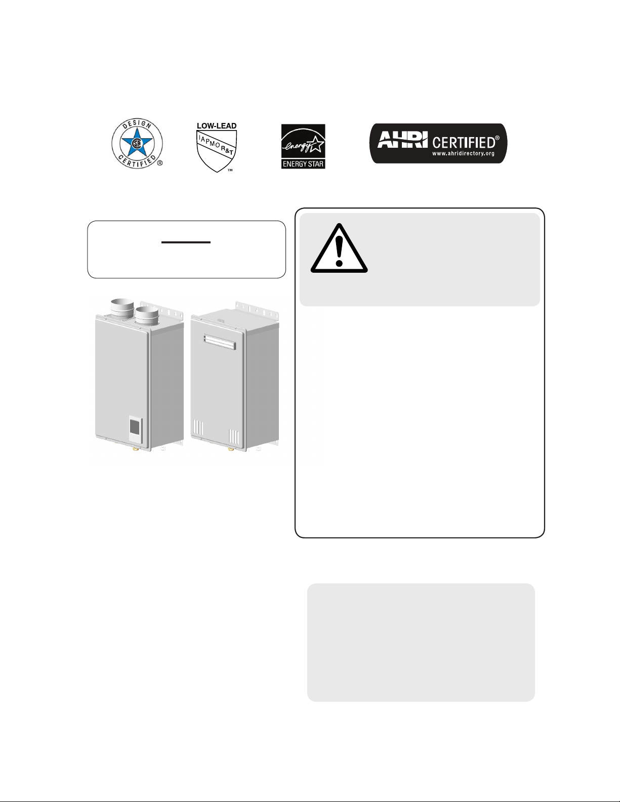
On-Demand Water Heater
Installation Manual and Owner’s Guide
ANSI Z21.10.3 • CSA 4.3
Model
• 140 Outdoor• 140 Indoor
Gas Tankless Water Heater
Suitable for combination potable water heating
and space heating. Please refer to local codes for
space-heating compliance.
TM
If the information in these
instructions is not followed
exactly, a fire or explosion may
WARNING
- Do not store or use gasoline or other
flammable vapors and liquids in the vicinity
of this or any other appliance.
- WHAT TO DO IF YOU SMELL GAS
• Do not try to light any appliance.
• Do not touch any electric switch, do not
use any phone in your building.
• Immediately call your gas supplier from
a neighbor's phone. Follow the gas
supplier's instructions.
• If you cannot reach your gas supplier, call
the fire department.
- Installation and service must be performed
by a qualified installer, service agency or the
gas supplier.
result causing property damage,
personal injury or death.
FEATURING
• ENDLESS HOT WATER
• ON-DEMAND USAGE
• COMPACT, SPACE SAVING
• ENERGY CONSERVATION
• COMPUTERIZED SAFETY
• NO PILOT LIGHT
• Complies with SCAQMD Rule
1146.2 for natural gas Low NOx
Emissions of 14 ng/J or 20 ppm.
Keep this manual near the water heater for future reference whenever maintenance, adjustment, or
service is required.
If you have any questions, please
call or write to:
500 Tennessee Waltz Parkway
Ashland City, TN 37015
Toll Free: 1-877-737-2840
Page 2

CONTENTS
Installation Manual
Contents
Installation Manual
SPECIFICATIONS .............................................4
INTRODUCTION ..........................................5
SAFETY GUIDELINES.....................................6
SAFETY DEFINITION ....................................6
GENERAL ......................................................6
INSTALLATION ................................................7
GENERAL ......................................................7
CLEARANCES ...............................................9
INCLUDED ACCESSORIES ............................9
OPTIONAL ITEMS ........................................9
WARNING FOR INSTALLATIONS ............... 11
.............12
VENTING INSTRUCTIONS .........................13
General .....................................................13
Combustion air supply .............................. 14
Exhaust vent (ABS,PVC,CPVC, or
polypropylene vent) .................................18
DIP switch settings for vent length
(ABS,PVC,CPVC, or polypropylene vent) ... 19
Exhaust vent (Stainless steel vent) ...........22
DIP switch settings for vent length
(Stainless steel vent) .................................23
Vent termination clearances ....................25
Clearances for sidewall terminations .......26
Clearances for rooftop terminations ........27
GAS SUPPLY AND GAS PIPE SIZING .........28
General .....................................................28
Gas connections .......................................28
Natural Gas supply piping .........................29
Propane (LP) supply piping ....................... 29
WATER CONNECTIONS .............................30
Pressure relief valve .................................30
CONDENSATE DRAIN ................................31
Condensate drain connections .................31
ELECTRICAL CONNECTIONS ..................... 33
TEMPERATURE REMOTE CONTROLLER .....33
Included accessories ................................. 33
Installation ................................................ 34
APPLICATIONS .............................................. 35
Space heating applications .........................35
Recirculation ............................................... 35
Dual-purpose hot water heating ...................36
INITIAL OPERATION .....................................37
Owner's Guide
OPERATING SAFETY .....................................39
NORMAL OPERATION ..................................41
......41
GENERAL ....................................................41
TEMPERATURE TABLE OF CONTROLLER . 41
OUTLET WATER TEMPERATURE
SETTING ..................................................... 42
Using controller .......................................42
Temperature setting on the PCB ..............42
ADDITIONAL FEATURES ............................43
Information mode ....................................43
Unit conversion mode ..............................43
FLOW .......................................................... 44
FREEZE PROTECTION SYSTEM .................44
MAINTENANCE AND SERVICE ................. 44
Measuring inlet gas pressure .....................45
UNIT DRAINING AND FILTER CLEANING ....... 45
TROUBLESHOOTING .....................................46
ERROR CODES ...........................................47
Fault analysis error code ..........................48
COMPONENTS DIAGRAM ............................50
PARTS LIST .................................................... 54
OUTPUT TEMPERATURE CHART ..................56
This installation manual is approved for installation in the United States.
2 Page
Page 3
Installaon Manual
Installation Manual
CONGRATULATIONS
Congratulations and thank you for choosing our tankless water heater.
Before use, we recommend that you read through this installation
manual carefully. Keep this manual for future reference.
If you need an additional manual, contact the manufacturer or your
local distributor. When you call, please tell us the product name and
the serial number of your unit written on the rating plate of the water
heater.
3 Page
Page 4
SPECIFICATIONS
Installation Manual
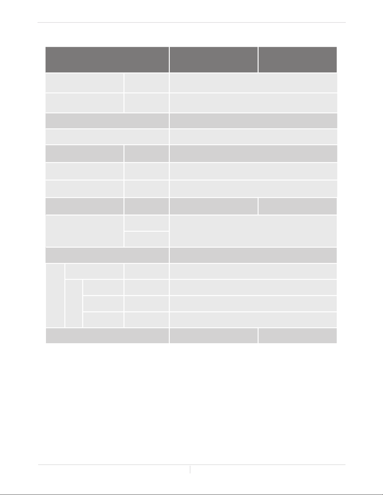
Specifications
Model
Natural Gas Input
(Operating Range)
Propane Input
(Operating Range)
BTU/h
BTU/h
140 Indoor 140 Outdoor
Min.: 15,000
Max.: 120,000
Min.: 15,000
Max.: 120,000
Gas Connection 1/2" NPT
Water Connection 3/4" NPT
Water Pressure*
Natural gas
Inlet Pressure
Propane
Inlet Pressure
Weight
Dimension
psi
(MPa)
inch W.C.
(kPa)
inch W.C.
(kPa)
15 - 150 (0.1 - 1.0)
Min. 4.0 (1.0)
Max. 10.5 (2.6)
Min. 8.0 (2.0)
Max. 14.0 (3.5)
lbs. (kg) 50 (22.5) 50 (22.5)
inch
mm
H 21-3/4 x W 14 x D 9-1/4
H 552 x W 352 x D 236
Ignition Electric Ignition
Electric
Supply VAC / Hz
Operation W / A
Standby W / A
Freeze-
Consumption
Protection
W / A
120 / 60
53.9 / 0.7
3.2 / 0.05
223.9 / 1.94
Water heater category** Category IV N/A
*40 psi or above is recommended for maximum flow.
**Water heater Category — water heaters of other than direct vent type, for outdoor installation, are divided into four
categories based on static pressure produced in the vent and flue loss.
Category I - a water heater that operates with a non-positive vent static pressure and with a vent gas temperature
that avoids excessive condensate production in the vent.
Category II - a water heater that operates with a non-positive vent static pressure and with a vent gas temperature
that may cause excessive condensate production in the vent.
Category III - a water heater that operates with a positive vent static pressure and with a vent gas temperature that
avoids excessive condensate production in the vent.
Category IV - a water heater that operates with a positive vent static pressure and with a vent gas temperature that
may cause excessive condensate production in the vent.
NOTE:
The manufacturer reserves the right to discontinue, or change at any time, specifications or designs
without notice and without incurring obligation.
4 Page
Page 5
Installation Manual
Introduction
INTRODUCTION
This manual provides information necessary for the installation, operation, and maintenance
of the water heater.
The model description is listed on the rating plate which is attached to the side/front panel of
the water heater.
Please read all installation instructions completely before installing this product.
If you have any problems or questions regarding this equipment, consult the manufacturer or
its local representative.
This equipment is an on-demand, tankless water heater designed to efficiently supply endless
hot water for your needs.
These high efficiency models have a built-in secondary heat exchanger that absorbs latent
heat from the exhaust gas.
The 140 Indoor model is only to be installed indoors. The 140 Outdoor model is only to be
installed outdoors.
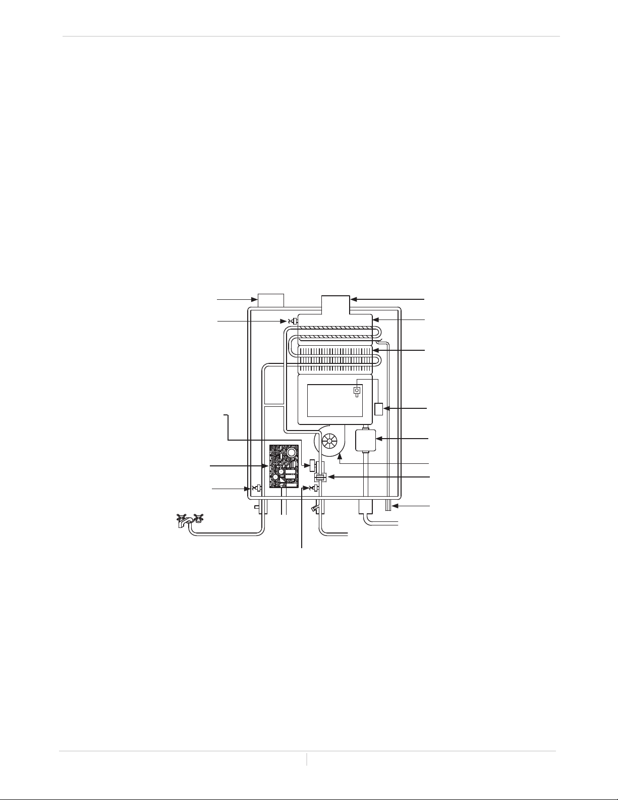
The principle behind tankless water heaters is simple:
Intake port
Exhaust
Thermistor
Water control
valve
Computer
board
Thermistor
Hot water outlet
Burners
Cold water inlet
Thermistor
Exhaust
Secondary
heat exchanger
Primary
heat exchanger
Igniter
Gas valve
Fan motor
Flow sensor
Condensate
drain port
Gas inlet
*This diagram illustrates tankless water heater design concepts only and does not accurately
represent the water heater’s physical description.
1. A hot water fixture is turned on.
2. Water flows through the heater.
3. The water flow sensor detects the water flow.
4. The computer initiates the fan motor and gas valve to let gas flow through the heater and sends a
signal to the igniter to create an ignition spark.
5. The gas ignites and flames appear within the burner chamber.
6. Water is heated as it flows through the heat exchanger.
7. Using thermistors to measure temperatures throughout the water heater, the computer modulates
the gas and water valves to ensure proper output water temperature and hot water outflows.
8. When the fixture is turned off, the unit shuts down.
5 Page
Page 6
SAFETY GUIDELINES
SAFETY DEFINITION
Indicates an imminently hazardous situation which, if not avoided, will result in
death or serious injury.
DANGER
Indicates an imminently hazardous situation which, if not avoided, could result
in death or serious injury.
WARNING
Indicates an imminently hazardous situation which, if not avoided, could result
in minor or moderate injury.
CAUTION
Installation Manual
Safety Guidelines
NOTICE
Indicates information considered important but not hazard related.
GENERAL
1. Follow all local codes, or in the absence of local codes, follow the current edition of the National
Fuel Gas Code: ANSI Z223.1/NFPA 54 in the USA or B149.1 Natural Gas, Propane Installation Code in
Canada.
2. Properly ground the unit in accordance with all local codes or in the absence of local codes, with the
National Electrical Codes: ANSI/NFPA 70 in the USA or CSA standard C22.1 Canadian Electrical Code
Part 1 in Canada.
3. Carefully plan where you intend to install the water heater. Please ensure:
Your water heater will have enough combustible air and proper ventilation.
Locate your heater where water leakage will not damage surrounding areas. (Please refer to p. 8.)
4. Check the rating plate for the correct GAS TYPE, GAS PRESSURE, WATER PRESSURE and ELECTRIC
RATING.
*If this unit does not match your requirements, do not install and consult with the manufacturer.
5. If any problem should occur, turn off all hot water taps and turn off the gas. Then call a trained
technician, the gas company, or the manufacturer.
Water temperatures over 125 °F (52 °C) can cause severe burns instantly or death from
scalding. The water temperature is set at 120 °F (50 °C) from the factory to minimize any
scalding risk. Before bathing or showering always check the water temperature.
Do not store or use gasoline or other flammables, vapors, or liquids in the vicinity of this
WARNING
appliance.
Do not reverse the water and/or gas connections as this will damage the gas valves and
can cause severe injury or death. Follow the diagram on p. 30 when installing your water
heater.
Should overheating occur or the gas supply fails to shut off, turn off the manual gas control
valve to the appliance.
Do not use this appliance if any part has been in contact with or been immersed in water.
Immediately call a qualified installer or service agency to replace a flooded water heater.
Do not attempt to repair the unit. It must be replaced.
Do not disconnect the electrical supply if the ambient temperature will drop below
freezing. The Freeze Protection System only works if the unit has electrical power. The
warranty will not be covered if the heat exchanger is damaged due to freezing. Refer to
the section on the Freeze Protection System on p. 44 for more information.
Failure to observe these warnings could result in severe personal injury or death.
6 Page
Page 7

Installation Manual
Installaon
INSTALLATION
GENERAL
1. Follow all local codes, or in the absence of local codes, follow the current edition of the National
Fuel Gas Code: ANSI Z223.1/NFPA 54 in the USA or B149.1 Natural Gas, Propane Installation Code in
Canada.
2. All gas water heaters require careful and correct installation to ensure safe and efficient operation.
This manual must be followed exactly. Read the “Safety Guidelines” section.
3. The manifold gas pressure is preset at the factory. It is computer controlled and should not need
adjustment.
4. Maintain proper space for servicing. Install the water heater so that it can be connected or removed
easily. Refer to the "Clearances" section on p. 9 for proper clearances.
5. The water heater must be installed in a location where the proper amount of combustible air will be
available to it at all times without obstructions, or the indoor heater may be direct vented.
6. Electrical service to the water heater requires a means of disconnection. This will allow power to the
water heater to be shut off for servicing and safety purposes.
7. Do not install the unit where the exhaust vent is pointing into any opening in a building or where the
noise may disturb your neighbors. Make sure the vent termination meets the required clearance from
any doorway or opening to prevent exhaust from entering a building. (Refer to pp. 11, 25 and 26.)
Check local code requirements prior to installation.
8. Carefully plan the installation location of the heater and vent terminations. Contaminants such as
aerosols, lint, and fine powders (including flour) can clog the air intake and reduce the operation of the
fan. This, in turn, can cause improper combustion and reduce the life of the water heater. Regularly
ensure that the area around the water heater, vent termination, and air intake is free of dust, debris,
and other contaminants. In environments with a high level of contaminants (laundry facilities, hair
salons, pet salons, chemical plants, commercial kitchens, etc.), direct venting is required.
9. The 140 Indoor model is to be installed indoors only. The model is equipped with a thermistor and
hi-limit switch for the exhaust gas, detecting excess temperatures within the flue and enabling the
water heater to safely stop operation if needed. These components are always monitoring exhaust gas
conditions in order to prevent heat damage to ABS, PVC (solid core), CPVC (solid core), or Polypropylene
(Plastic) venting if ABS, PVC, CPVC, or Polypropylene is used. If the exhaust gas temperature exceeds
140 °F (60 °C) these components will enable the water heater to safely stop operation. (These
components are not installed on the outdoor model since the exhaust vent is built-in.)
If the water heater is used as a direct-vent appliance, the unit requires 3 in (76 mm) or 4 in (102
mm) combustion air supply pipe. The intake pipe must be sealed airtight. Refer to pp. 13 to 27
for more detail.
Air supply pipe can be made of aluminum flexible tube, ABS, PVC (solid core), CPVC (solid core),
Polypropylene, corrugated stainless steel, or Category lll / IV stainless steel. Regarding exhaust
pipe, please refer to pp.18 to 24 for detailed information.
Use of cellular core PVC (ASTM F891), cellular core CPVC, or Radel® (polyphenylsulfone) in non-
metallic venting systems is prohibited. Covering non-metallic vent pipe and fittings with thermal
insulation is prohibited.
Terminating the venting through a sidewall is recommended for the direct-vent system.
Terminating in the same pressure zone allows for pressure balancing, which prevents nuisance
shutdowns.
Only install the water heater in a heated area where below freezing temperatures cannot occur. The
warranty does not cover damage caused by freezing.
The manufacturer recommends running the exhaust vent and the intake pipe as parallel as possible.
The water heater must be securely mounted to a wall or other suitable structure.
10. The 140 Outdoor model must only be installed outdoors and only in the area with mild, temperate
climates. The Outdoor model shall be wall-mounted or mounted on a stand. Locate the Outdoor
model in an open, unroofed area and maintain the minimum clearances. (Refer to pp.9 and 11.)
7 Page
Page 8
WARNING
Installaon Manual
Installaon
Installation and service must be performed by a qualified installer (for example, a
licensed plumber or gas fitter). Otherwise, the warranty will be void.
The installer (licensed professional) is responsible for the correct installation of the
water heater and for compliance with all national, state/provincial, and local codes.
The manufacturer does not recommend installing the water heater in a pit or
location where gas and water can accumulate.
Do not have the vent terminal pointing toward any operating window, door, or
opening into a building.
Do not install next to any source of airborne debris, such as a clothes dryer, that
can cause debris to be trapped inside the combustion chamber, unless the system is
direct-vented.
Do not install the unit where water, debris, or flammable vapors may get into the flue
terminal or the air intake line.
The manufacturer does not recommend installing the water heater in an attic due
to safety issues. If you install the water heater in an attic:
Make sure the unit will have enough combustion air and proper ventilation.
Failure to do so could lead to carbon monoxide poisoning or death.
Keep the area around the water heater clean. When dust collects on the flame
sensor, the water heater will shut down on an error code.
Place the unit where it will allow easy access for service and maintenance.
A drain pan, or other means of protection against water damage, is
recommended to be installed under the water heater in case of leaks.
Failure to observe these warnings could result in severe personal injury, death,
and/or property damage.
NOTICE
The warranty will not cover damage caused by water quality.
Only potable water can be used with this water heater. Do not introduce pool
or spa water, or any chemically treated water into the water heater.
Water hardness levels must not exceed 7 grains per gallon (120 ppm) for
single family domestic applications or more than 4 grains per gallon (70 ppm)
for all other types of applications. Water hardness leads to scale formation
and may affect/damage the water heater. Hard water scaling must be avoided
or controlled by proper water treatment.
Water pH levels must be between 6.5 and 8.5.
Well water must be treated.
The manufacturer recommends direct venting when the water heater is installed
in beauty salons, dry cleaners or any other locations in which such chemicals
are present in the air. Some chemicals used in beauty salons or dry cleaners may
affect the flame sensor. In such cases, the water heater may not work properly.
Although the water heater is designed to operate with minimal sound, the
manufacturer does not recommend installing the unit on a wall adjacent to a
bedroom, or a room that is intended for quiet study or meditation, etc.
Locate your heater close to a drain where water leakage will not do damage to
surrounding areas. As with any water heating appliance, the potential for leakage
at some time in the life of the product does exist. The manufacturer will not be
responsible for any water damage that may occur. If you install a drain pan under
the unit, ensure that it will not restrict the combustion air flow.
8 Page
Page 9
Installaon Manual
Installaon
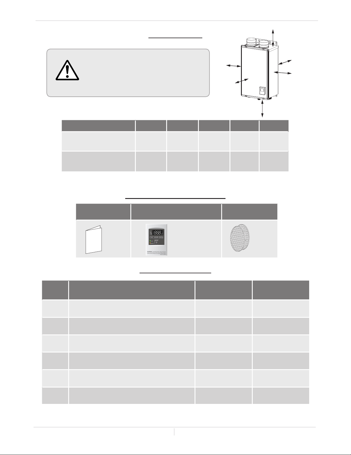
Maintain all clearances around the water
heater. Failure to do so could create a fire
hazard, potentially leading to death, serious
WARNING
*24 inches recommended for maintenance.
injury, and/or property damage.
Model Top Bottom Front Back Sides
140 Indoor
140 Outdoor
(305 mm)
(914 mm)
INCLUDED ACCESSORIES
CLEARANCES
12 in.
36 in.
12 in.
(305 mm)
12 in.
(305 mm)
4 in.*
(102 mm)
24 in.
(610 mm)
Side
Front
1 in.
(25 mm)
1 in.
(25 mm)
Top
Back
Side
Boom
3 in.
(76 mm)
3 in.
(76 mm)
Installation manual
and owner’s guide
Qty: 1
Temperature remote controller kit*
Outdoor model only
# Model
1.
2.
3.
4.
4-inch Exhaust Sidewall Vent Terminator (Hood)
Temperature Remote Controller
Pipe Cover
Neutralizer Kit
and 4-inch Wall Thimble
100209924
(TM-RE42)
Qty: 1
OPTIONAL ITEMS
Bird screen
Indoor model only
Qty: 2
140 Indoor 140 Outdoor
✓
Included with the
water heater
✓ ✓
✓ ✓
✓
5.
6.
3-inch Concentric PVC
Termination
Recess Box
✓
✓
9 Page
Page 10
Installaon Manual
Installaon
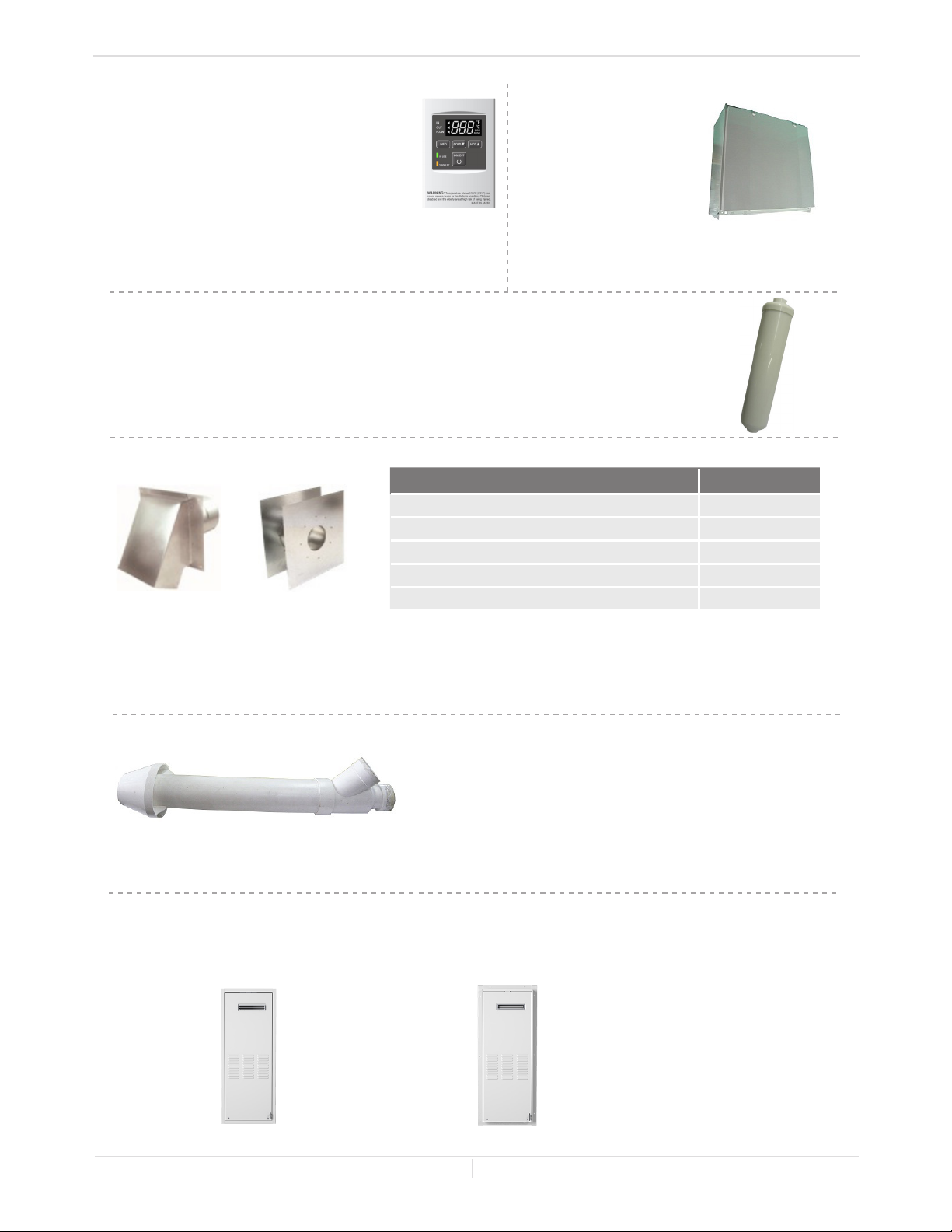
1. Temperature remote controller:
100209924 (TM-RE42)-Standard model
The temperature remote controllers have
three functions. It allows the output
temperature from the water heater to
be adjusted. It also works as a diagnostic
tool and provides a concise error code
whenever there is a problem with the unit. See the
Troubleshooting Section (pp.53 to 56) for information
on possible error codes.
3. Neutralizer kit: 100112159 (TH-NT01)
The neutralizer assembly neutralizes the condensate (acidic water) that forms in the
secondary heat exchanger of the water heater.
It connects to the condensate drain port of the water heater with connectors included
with the neutralizer kit. (Refer to pp. 32 and 33.)
4. Sidewall vent terminator (Hood) and Wall thimble:
Covering wall thicknesses Part#
Wall Thimble 4 - 7 in (102 - 178 mm) 100112732
Wall Thimble 5 - 10 in (123 - 254 mm) 100112733
Termination + Thimble 4 - 7 in (102 - 178 mm) 100112424
Terminator Hood
Wall Thimble
Termination + Thimble 5 - 10 in (123 - 254 mm) 100112425
2. Pipe cover:
100187904 (TH-PC04)
The pipe cover protects
the plumbing pipes to
the water heater from
unexpected adjustments.
This pipe cover is fixed
to the bottom of the
water heater, which hides the plumbing and
improves the visual aspects of the whole
installation.
Terminator Hood 100112419
These are used when venting out through the wall. These terminations are special stainless steel
vents for gas appliances and are UL listed as Category II, III and IV. For different wall thicknesses, there
are two ranges of lengths available. (Refer to the NovaVent brochure for details.) Install these vent
terminations in accordance with their installation instructions and any applicable local codes.
5. 3" PVC concentric termination: 100112163 (TH-CVPVC33)
Used when terminating direct-vent (sealed combustion)
systems, with Indoor models that require a 3 in. (76 mm) intake
and a 3 in. (76 mm) exhaust.
This concentric termination provides the convenience of only having to make one penetration through a
sidewall instead of two separate penetrations for the intake and exhaust piping. The termination includes
a bird screen, restricting small animals, pests, and foreign objects from entering into the vent system.
6. Recess box:
It allows for “clean” installations. The water heater fits inside the recess box, which hides and
protects the whole water heater and plumbing. The recess box will fit between most wall studs.
Outdoor recess box
for retrofit applications-no flange
Outdoor recess box
for new construction applicationswith flange
100266729
100266730
10 Page
Page 11
Installaon Manual
Installaon
WARNING FOR INSTALLATIONS
FOR YOUR SAFETY, READ BEFORE INSTALLATION:
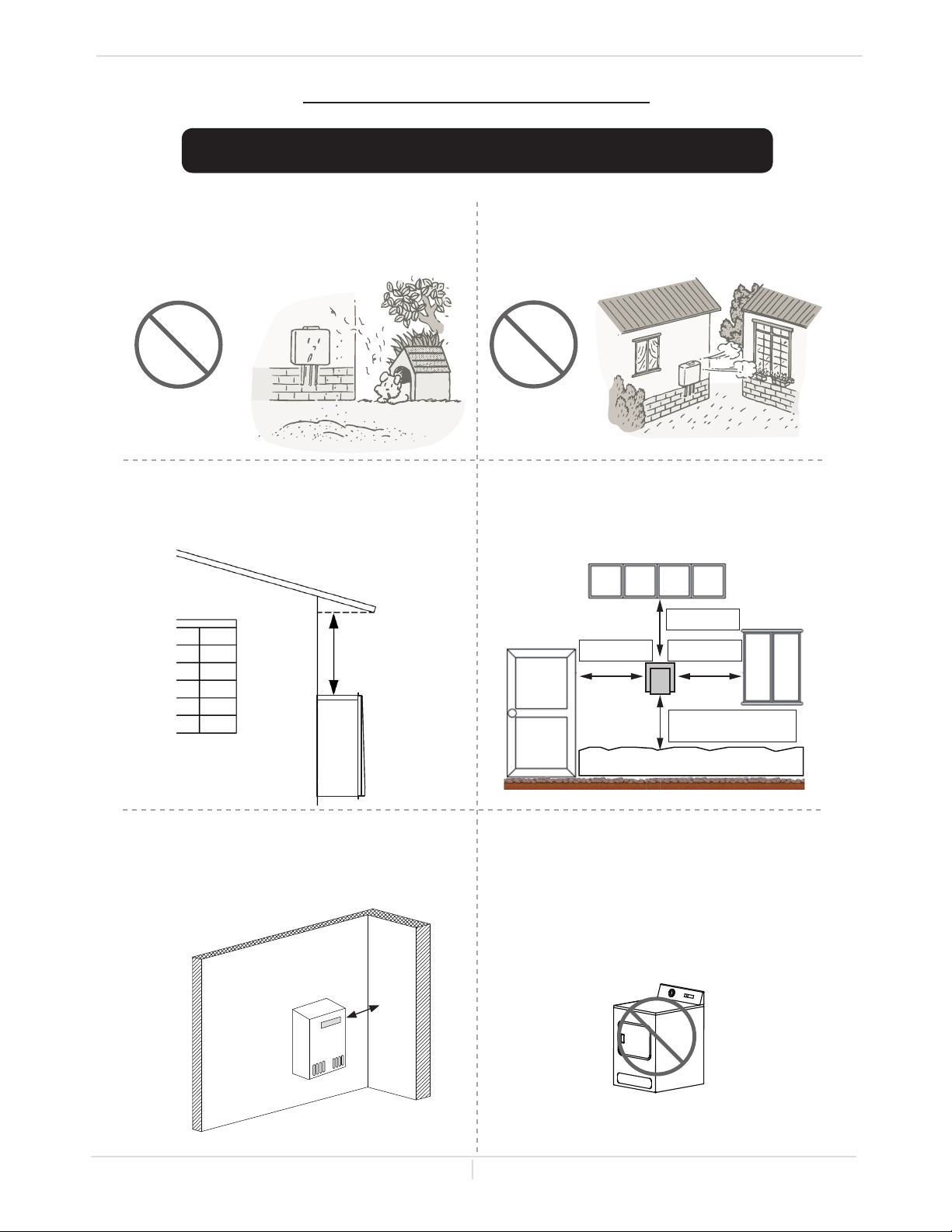
Do not install the heater where water, debris or
flammable vapors may get into the flue terminal.
This may cause damage to the heater and void the
warranty.
Prohibited
Do not install this water heater under an
overhang less than 3 ft (914 mm) from its top
or eaves. The area under an overhang must be
open to three sides (Outdoor model only).
3 ft
(914 mm)
Do not have the vent terminal pointing toward
any opening into a building. Do not locate your
heater in a pit or location where gas and water
can accumulate.
Prohibited
Ensure that you meet the minimum clearances
shown below for a direct vent termination:
USA: 1 (30 cm) min.
Canada: 3 (91 cm) min.
USA: 1 (30 cm) min.
Canada: 3 (91 cm) min.
USA: 1 (30 cm) min.
Canada: 3 (91 cm) min.
Water heater vent terminator must be at least 2
ft (610 mm) away from an inside corner for both
outdoor installation and direct-vent installation.
2 ft
(610 mm)
Inside
Corner
USA: 12 in. (30 cm) above grade and
above ancipated snow level
Canada: 12 in. (30 cm) above grade
Ancipated snow level
Do not install next to a dryer or any source
of airborne debris that can be trapped inside
the combustion chamber, unless the system is
direct-vented.
11 Page
Page 12
12 Page
Page 13
Installaon Manual
Installaon
VENTING INSTRUCTIONS
Indoor model
-General-
Improper venting of this appliance can result in excessive levels of carbon
monoxide which can result in severe personal injury or death.
Improper installation can cause nausea or asphyxiation, severe injury or death
from carbon monoxide and flue gases poisoning. Improper installation will void
WARNING
The Indoor model must be vented in accordance with “Venting of Equipment" in the current edition of the
National Fuel Gas Code: ANSI Z223.1/NFPA 54 in the United States and/or Section 8 of the B149.1 Natural
Gas and Propane Installation Code in Canada, as well as applicable local building codes.
The use of venting materials approved for Category III/IV appliances is recommended whenever possible.
However, the Indoor model may also be vented with plastic pipe materials such as ABS, PVC (solid core),
CPVC (solid core), or polypropylene. For details, please refer to the Exhaust Vent (ABS, PVC, CPVC, or
Polypropylene Vent) Section on p. 18. Vent installations in Canada which utilize plastic vent systems must
use venting that complies with ULC S636.
General rules for venting water heaters:
Place the water heater as close as possible to the vent termination.
The vent collar of the water heater must be fastened directly to an unobstructed vent pipe.
Do not weld the vent pipe to the water heater’s vent collar.
Do not cut or alter the vent collar of the unit.
The vent must be easily removable from the top of the water heater for normal service and inspection of
the unit.
The water heater vent must not be connected to any other gas appliance or vent stack.
Avoid using an oversized vent pipe or using extremely long runs of the pipe unless it is part of an approved
common vent system.
Air supply pipe can be made of ABS, PVC (solid core), CPVC (solid core), polypropylene, corrugated stainless
steel, or Category lll / IV stainless steel. Regarding exhaust pipe, refer to pp.18 to 24.
Use of cellular core PVC (ASTM F891), cellular core CPVC, or Radel® (polyphenylsulfone) in nonmetallic
venting systems is prohibited. Covering non-metallic vent pipe and fittings with thermal insulation is
prohibited.
Sidewall venting is recommended for the Indoor model. Vertical venting (roof termination) is acceptable.
The manufacturer recommends running the exhaust vent and the intake pipe as parallel as possible.
For rooftop venting, a rain cap or other form of termination that prevents rain water from entering into
the water heater must be installed.
Do not terminate vent into a chimney. If the vent must go through the chimney, the vent must run all the
way through the chimney with approved vent pipe.
The water heater shall not be connected to a chimney flue serving a separate appliance, designed to burn
solid fuel.
General rules for vent terminations:
Avoid locating the water heater vent termination near any air intake devices. These fans can pick up the
exhaust flue products from the water heater and return them to the building. This can create a health
hazard.
Locate the vent termination so that it cannot be blocked by any debris, at any time. Most codes require
that the termination be at least 12 in (305 mm) above grade and anticipated snow level, but the installer
may determine if it should be higher depending on the job site condition and applicable codes.
A proper sidewall termination is recommended when the water heater is vented through a sidewall.
Regarding the clearances from the exhaust termination to the air inlet or opening, refer to pp. 25 to 27.
product warranty.
When installing the vent system, all applicable national and local codes must be
followed. If you install thimbles, fire stops or other protective devices and they
penetrate any combustible or noncombustible construction, be sure to follow
all applicable national and local codes.
13 Page
Page 14
Installaon Manual
Installaon
-Combuson air supply-
This gas water heater requires an adequate source of clean air for combustion and
ventilation. Without sufficient air, your water heater may not operate properly and
may emit excessive and abnormal amounts of carbon monoxide which may result in
WARNING
NOTICE
Before installing the water heater, you must determine the amount of air needed to supply this water
carbon monoxide poisoning or death.
• The guidelines in this section apply to installations within the United States. All
U.S. installations must conform to the National Fuel Gas Code, ANSI Z223.1/NFPA
54 (current edition) and local codes.
• Canadian requirements differ from the guidelines in this section. In Canada,
follow the requirements of B149.1 (Natural Gas and Propane Installation Code,
current edition) as well as local and provincial codes. Contact your local code
enforcement agency for direction.
Check for Chemicals:
these corrosive chemicals is not covered by the warranty.
WARNING!
In all cases, ensure that corrosive chemicals are not present at the air intake. Presence of such chemicals
require outside air due to chemicals include:
Beauty salons
Photo processing labs
Indoor pools
Chemical storage areas
Products such as aerosol sprays, detergents, bleaches, cleaning solvents, gasoline, air fresheners, paint and
varnish removers, and refrigerants should not be stored or used near the water heater.
Does your installation space have sufficient combustion air?
CalculatetotalBTU/hrangofallappliances.
ing appliances (e.g., water heaters, furnaces, clothes dryers) in the same area. Do not include appliances
that are direct vented. Refer to the following example.
14 Page
Page 15
Installaon Manual
Installaon
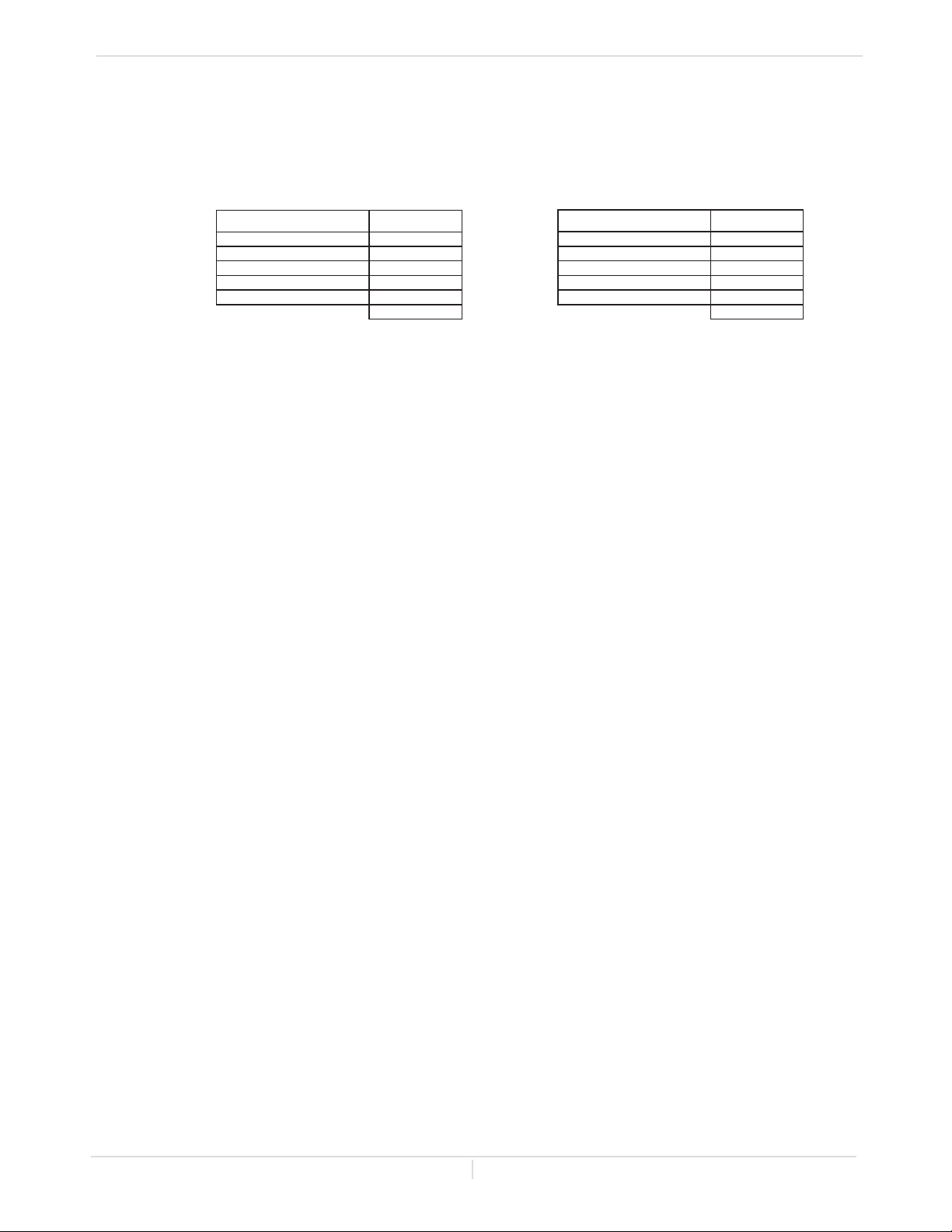
Your water heater’s BTU/h rating is on the rating plate. The BTU/h ratings should be on the other
appliances’ rating plates. If you have trouble determining the BTU/h ratings, contact the manufacturer
or have a qualified person determine the ventilation requirements.
NOTICE:
Example:
Gas Burning Appliance BTU/hRang
Gas Water Heater 120,000
Furnace 75,000
Dryer 20,000
Total 215,000
Your
appliances:
Gas Burning Appliance BTU/hRang
Gas Water Heater
Total
Calculate the air volume of the room
Air requirements depend on the size of the room.
32
If there are large objects in the room (e.g., refrigerator, furnace, car), subtract their volume from the vol-
Air Volume = Room Volume - Object Volume
Calculate required air volume
3
(1.42 m3) per 1,000 BTU/h of the total input for all gas burning appliances in the same area.
33 / 1000 (btu/h)
Example:
3
If the air volume of the room is less than the required air volume, you must direct vent the water heater
If the air volume of the room is greater than the required air volume, it may be possible to install the
as furnaces, whole house fans, and clothes dryers draw air out of your home. If they draw air out faster
”
Install with outside ventilation
Supplying outside air to the water heater typically requires two openings. One opening must be within 12 in
single opening is not preferred, you may use a single opening to outside air if the minimum free area is sized
according to Table 1
15 Page
Page 16
Installaon Manual
Installaon
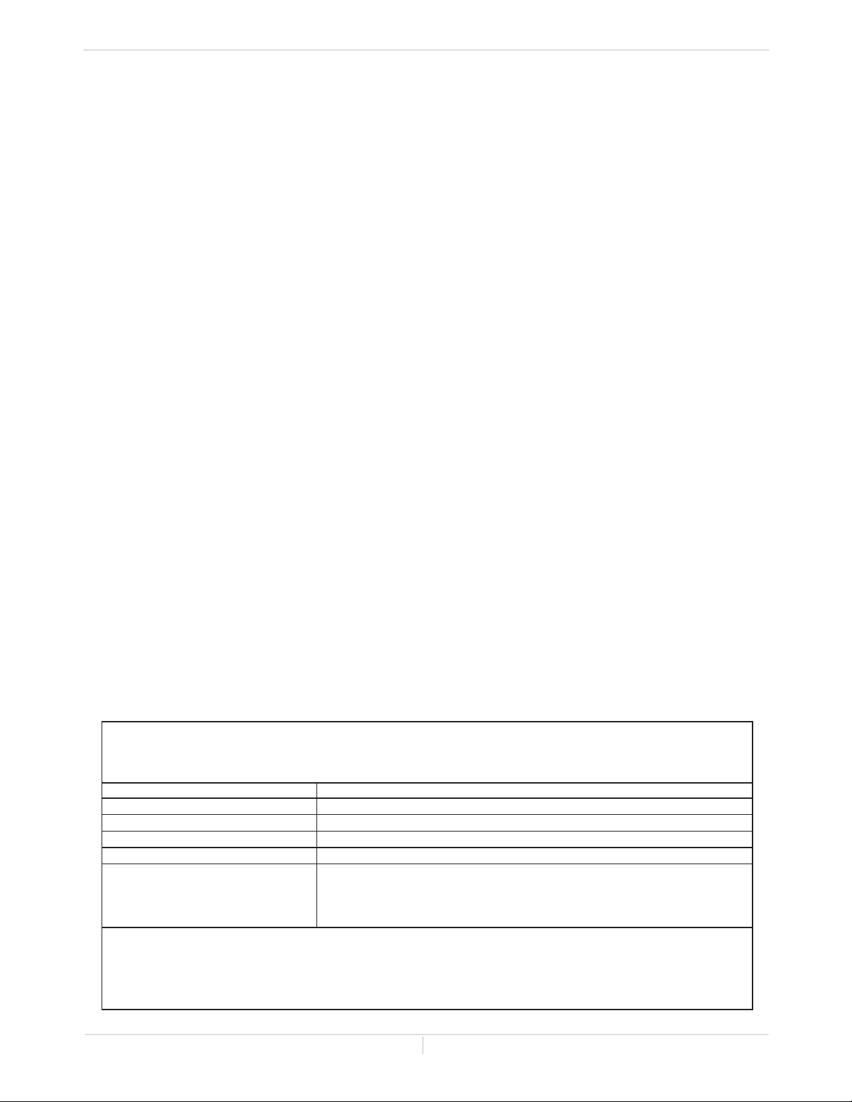
Determine type of ventilation
1. Direct to outdoors
2.
3. Horizontal ducts
4. Single opening (not recommended; must be at least 100 in2 (6.5 cm2
3 (1.42 m3
5. From a larger room inside the house (not recommended – refer to "Calculate the air volume of the room"
above to determine if the combined volume of the rooms may be adequate).
Determine minimum free area required for each vent opening
from “Before beginning”) and the type of vent used. Table 1 provides the minimum free area for each vent opening
Calculate minimum size of vent openings and ducts
vents use louvers or grilles to protect the opening. The louver or grill itself blocks some of the free area, so the opening may need to be larger to meet the minimum free area requirements.
2 (645 cm2) of free area would need
134 in2 (865 cm222).
Each vent opening must be no smaller than 100 in2 (645 cm2).
Rectangular ducts must have a minimum dimension of no less than 3 in (76 mm).
All screens must have mesh ¼” or larger.
-
Check that air source is clean and free of chemicals
Table 1
indoor spaces.
Opening Source Minimum Free Area
Direct to outdoors*
Horizontal ducts
Single Opening
Two permanent openings
to another room**
an outside wall.
See graphics on next page.
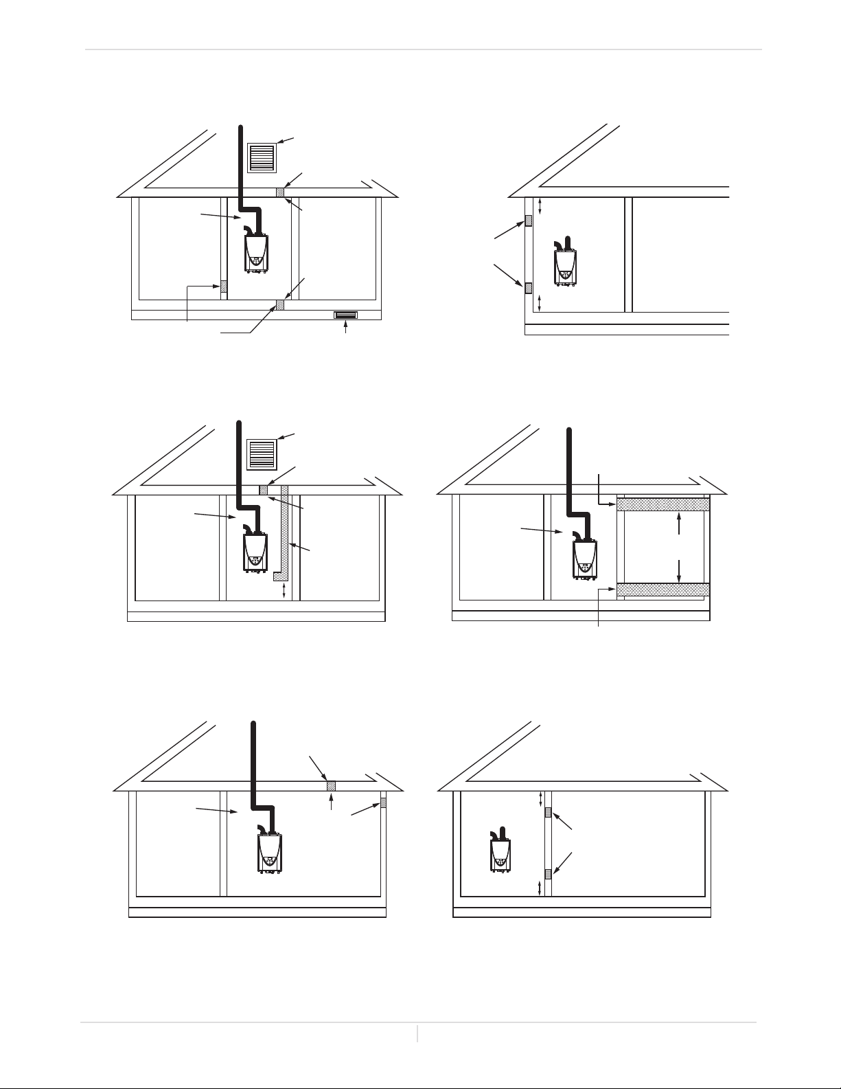
1 in2 (6.5 cm2) per 4,000 BTU/hr (see Figure 1, 2)
1 in2 (6.5 cm2) per 4,000 BTU/hr (see Figure 3)
1 in2 (6.5 cm2) per 2,000 BTU/hr (see Figure 4)
1 in2 (6.5 cm2) per 3,000 BTU/hr (see Figure 5)
1 in2 (6.5 cm2) per 1,000 Btu/hr (see Figure 6)
Opening: 100 in2 (645 cm2) MIn
Minimum dimension of air openings:
no less than 3 in (76 mm)
16 Page
Page 17
Combusonairsupplyopons
Gable vent
to outdoors
Install above
insulaon
Outlet air to
ac 1 in
2
(6.5 cm2)
per 4,000 btu/h
Inlet air from
the crawl space
Open foundaon vent
Confined
Space
Alternate
Air Inlet
1 in
2
(6.5 cm2)
per 4,000 btu/h
Outlet air to
ac 1 in
2
(6.5 cm2)
per 4,000 btu/h
Inlet air duct
1 in
2
(6.5 cm2)
per 4,000 btu/h
Confined
Space
12” (305 mm)
maximum
Gable vent
to outdoors
Install above
insulaon
Confined
Space
1 in2 (6.5 cm2)
per 3,000 btu/h
Alternave
Opening
Locaon
Two permanent
Openings
1 in2 per
1,000 btu/h
12” (305 mm)
maximum
12” (305 mm)
maximum
Confined
Space
1 in2 (6.5 cm2)
per 2,000 btu/h
Confined
Space
Outlet
Inlet
Outdoor
Air Ducts
1 in2 (6.5 cm2)
per 2,000 btu/h
Two permanent
Openings
1 in2 (6.5 cm2)
per 4,000 btu/h
12” (305 mm)
maximum
12” (305 mm)
maximum
Confined
Space
Installaon Manual
Installaon
Figure 1 - Direct to outdoors openings
duct openings
Figure 2 - Direct to outdoors openings
Two permanent openings
Figure 4 - Horizontal duct openings
Figure 5 - SIngle opening
Figure 6 - Two permanent openings
17 Page
Page 18
Installaon Manual
Installaon
-Exhaust vent (ABS, PVC, CPVC, or polypropylene vent)-
The Indoor model can be vented with ABS, PVC, CPVC, or polypropylene (temperature rated up to at
least 149 °F). Vent material certified to ULC S636 standards is recommended in the USA. In Canada,
plastic venting must be certified to ULC S636 standards.
Item Material United States Canada
Schedule 40 PVC ANSI/ASTM D1785
Exhaust pipe and
Fittings
Pipe Cement/Primer
Use of cellular core PVC (ASTM F891), cellular core CPVC, or Radel®
(polyphenylsulfone) in non-metallic venting systems is prohibited.
Covering non-metallic vent pipe and fittings with thermal insulation is prohibited.
PVC-DWV ANSI/ASTM D2665
Schedule 40 CPVC ANSI/ASTM F441
Schedule 40 ABS-DWV ANSI/ASTM D2661
Polypropylene UL-1738
PVC ANSI/ASTM D2564
CPVC ANSI/ASTM F493
ABS ANSI/ASTM D2235
ULC S636 Certified
Materials Only
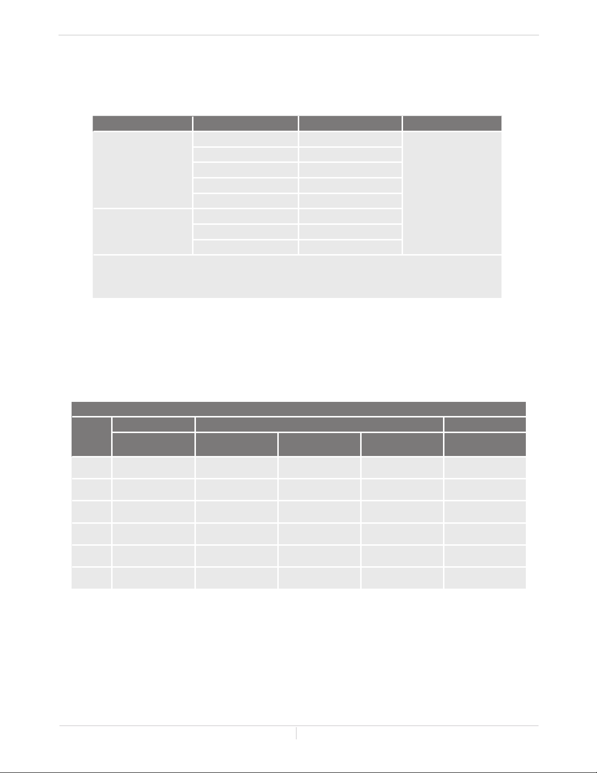
The maximum length of exhaust vent piping must not exceed 70 ft (21.3 m) for 3 inch venting,
which depends on the elevation where the water heater is installed, and 100 ft (30.5 m) for 4
inch venting (deducting 5 ft (1.5 m) for each elbow used in the venting system). Do not use more
than 5 elbows. See the table below.
When the horizontal vent run exceeds 5 ft (1.5 m), support the vent run at 3 ft (0.9 m) intervals
with overhead hangers.
Vertical or Horizontal (Total) Vent Length
No. of
Elbows*
0 6.5 ft (2.0 m) 70 ft (21.3 m) 40 ft (12.2 m) 25 ft (7.6 m) 100 ft (30.5 m)
1 1.5 ft (0.5 m) 65 ft (19.8 m) 35 ft (10.7 m) 20 ft (6.1 m) 95 ft (29.0 m)
2 N/A 60 ft (18.3 m) 30 ft (9.1 m) 15 ft (4.6 m) 90 ft (27.4 m)
3 N/A 55 ft (16.8 m) 25 ft (7.6 m) 10 ft (3.0 m) 85 ft (25.9 m)
4 N/A 50 ft (15.2 m) 20 ft (6.1 m) N/A 80 ft (24.4 m)
5 N/A 45 ft (13.7 m) N/A N/A 75 ft (22.9 m)
Excludes vent terminators, one termination elbow, or rain caps.
For details on the vent connection, refer to pp. 19 to 22.
*For each elbow added, deduct 5 ft (1.5 m) from max. vent length.
2" venting 3" venting 4" venting
0 to 3,000 ft
(0 to 914 m)
0 to 3,000 ft
(0 to 914 m)
3,001 to 6,000 ft
(915 to 1,829 m)
6,001 to 10,100 ft
(1,830 to 3,078 m)
0 to 10,100 ft
(0 to 3,078 m)
18 Page
Page 19
WARNING
OFF
1 2 3 4 5 6 7 8 9 10
Installaon Manual
Installaon
-DIP switch settings for vent length-
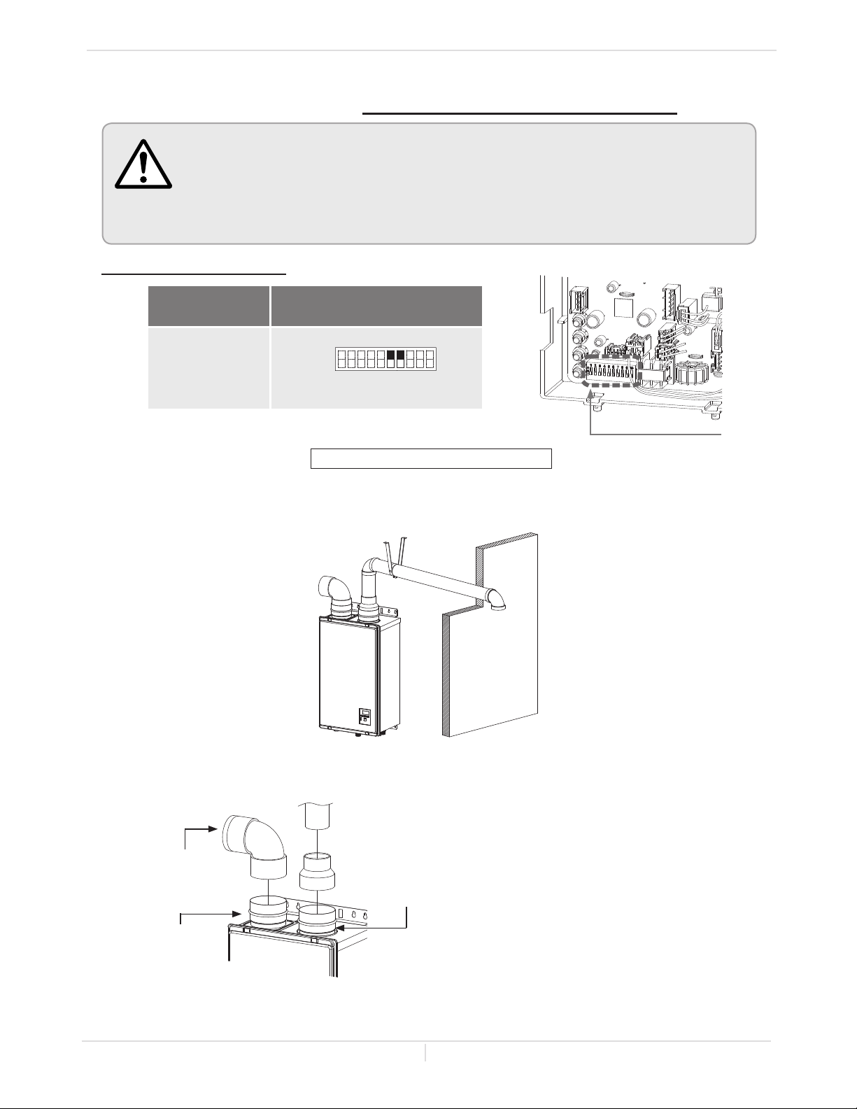
Typicalinstallaonsusing PVC, CPVC, ABS, or polypropylene vent
• Adjust the appropriate DIP switches according to vent size and vent length as
shown below. DO NOT adjust the other DIP switches.
• Turn off the power supply to the water heater before changing the DIP
switch settings.
• Failure to observe these warnings could lead to carbon monoxide poisoning
or death.
2inchventinstallaon
Vent length Single vent
5 to 6.5 ft
(1.5 to 2.0 m)
For details of the optional items, refer to the Installation manual for each optional item.
For clearance information, refer to pp. 25 to 27.
Computer board
ON
No. 6 : ON
No. 7 : ON
Bank of DIP switches
Single vent with room-air intake
Hanger
Termination
Vent connections for single vent
2" straight pipe
* 3" elbow with bird
screen
Intake vent
collar
(Female)
*The bird screen that fits into the 3 inch elbow is
supplied with the indoor water heater.
3"x2" reducer
Exhaust vent
collar (Female)
1. Connect a 3" elbow directly on the intake vent
collar of the water heater.
2. Connect a 3" x 2" reducer directly on the
exhaust vent collar of the wateheater. Make
sure the couplings engage the o-rings installed
in the intake and exhaust vent collars
3. Connect a 2" straight pipe to the reducer.
19 Page
Page 20
OFF
1 2 3 4 5 6 7 8 9 10
OFF
1 2 3 4 5 6 7 8 9 10
OFF
1 2 3 4 5 6 7 8 9 10
OFF
1 2 3 4 5 6 7 8 9 10
OFF
1 2 3 4 5 6 7 8 9 10
OFF
1 2 3 4 5 6 7 8 9 10
OFF
1 2 3 4 5 6 7 8 9 10
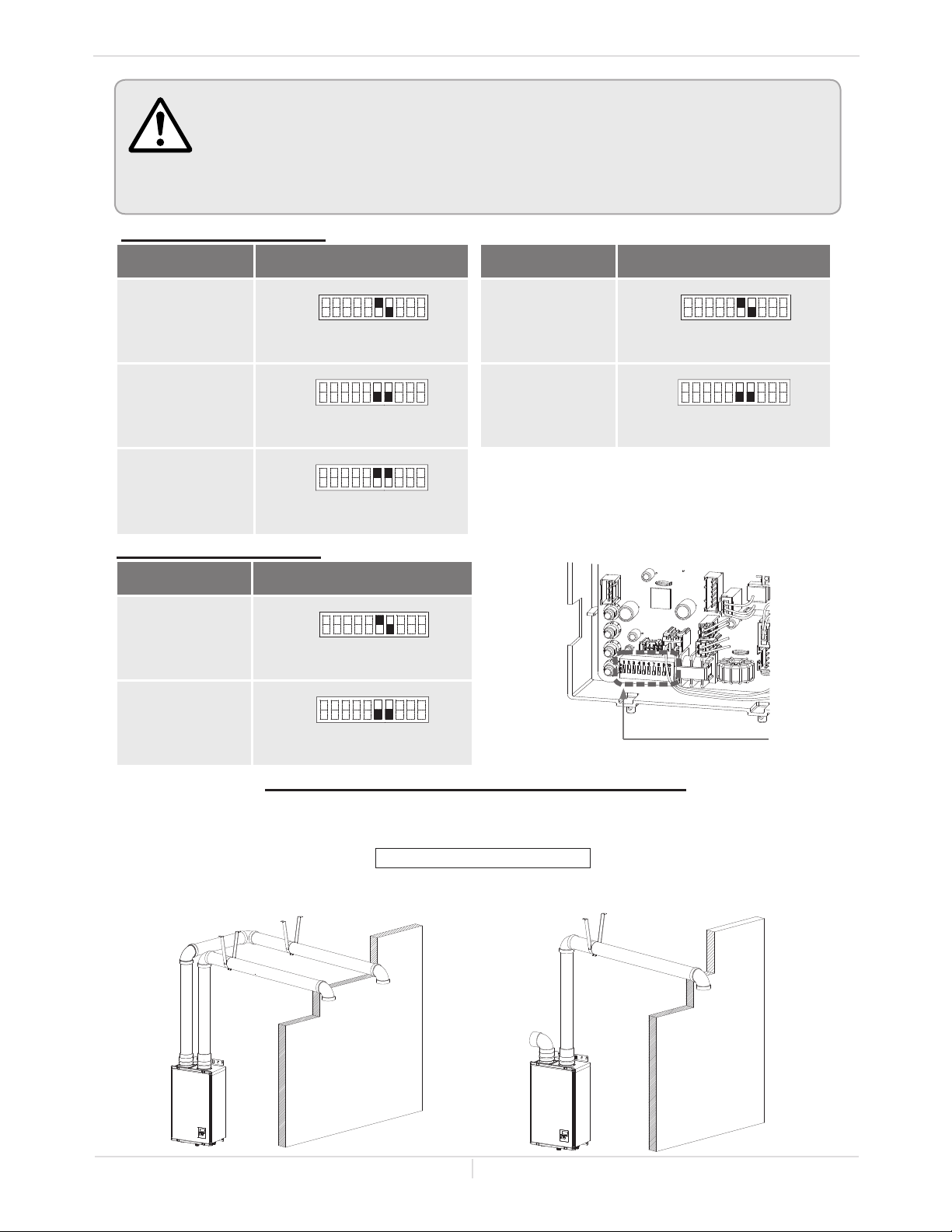
• Adjust the appropriate DIP switches according to vent size and vent length as
shown below. DO NOT adjust the other DIP switches.
• Turn off the power supply to the water heater before changing the DIP
WARNING
switch settings.
• Failure to observe these warnings could lead to carbon monoxide poisoning
or death.
3inchventinstallaon
Installaon Manual
Installaon
Vent length Direct vent
5 to 20 ft
ON
(1.5 to 6.0 m)
(DEFAULT)
No. 6 : ON
No. 7 : OFF
ON
21 to 40 ft
(6.1 to 12.2 m)
No. 6 : OFF
No. 7 : OFF
ON
Vent length Single vent
5 to 45 ft
(1.5 to 13.7 m)
(DEFAULT)
46 to 70 ft
(13.8 to 21.3 m)
41 to 70 ft
(12.3 to 21.3 m)
4inchventinstallaon
No. 6 : ON
No. 7 : ON
Computer board
Vent length Direct vent and Single vent
5 to 50 ft
ON
(1.5 to 15.2 m)
(DEFAULT)
No. 6 : ON
No. 7 : OFF
ON
51 to 100 ft
(15.3 to 30.5 m)
No. 6 : OFF
No. 7 : OFF
Bank of DIP switches
Examplesofinstallaonof3inch&4inchvent
For details of the optional items, refer to the Installation manual for each optional item.
For clearance information, refer to pp. pp. 25 to 27.
ON
No. 6 : ON
No. 7 : OFF
ON
No. 6 : OFF
No. 7 : OFF
Direct vent
Hanger
Hanger
Terminations
Horizontal installation
Single vent with room-air intake
Wall
20 Page
Hanger
Wall
Termination
Page 21
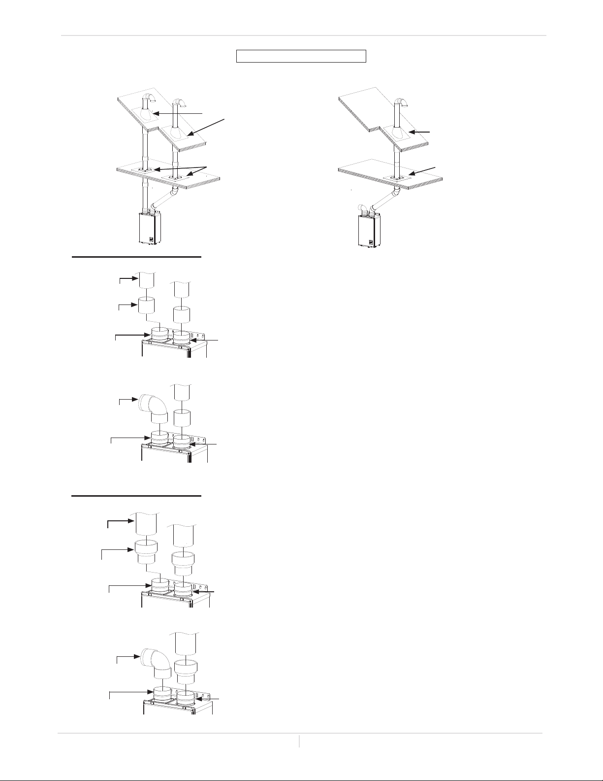
Roof
Direct vent
Installaon Manual
Installaon
Vertical installation
Single vent with room-air intake
Roof
Roof flashing
Roof flashing
Fire stop
3inchventinstallaon
Vent connections for direct vent
3" straight pipe
3" coupling
(included)
Intake vent collar
(Female)
3" straight pipe
3" coupling
(included)
Exhaust vent
collar (Female)
Vent connections for single vent
3" straight pipe
* 3" elbow with
bird screen
Intake vent collar
(Female)
*The bird screen that fits into the 3 inch elbow is supplied with the indoor water heater.
3" coupling
(included)
Exhaust vent
collar (Female)
1. Connect 3" couplings directly on the exhaust and
intake vent collar of the water heater. Make sure
the couplings engage the o-rings installed in the
intake and exhaust vent collars.
2. Connect 3" straight pipes to the couplings.
1. Connect a 3" elbow directly on the intake vent
collar of the water heater.
2. Connect a 3" coupling directly on the exhaust vent
collar of the water heater. Make sure the couplings
engage the o-rings installed in the intake and
exhaust vent collars.
3. Connect a 3" straight pipe to the coupling.
Fire stop
4inchventinstallaon
Vent connections for direct vent
4" straight
pipe
3"x4" increaser
Intake vent collar
(Female)
4" straight
pipe
3"x4"
increaser
Exhaust vent
collar (Female)
1. Connect 3"x4" increasers directly on the exhaust
and intake vent collar of the water heater. Make
sure the couplings engage the o-rings installed in
the intake and exhaust vent collars.
2. Connect 4" straight pipes to the increasers.
Vent connections for single vent
4" straight pipe
* 3" elbow with
bird screen
Intake vent collar
(Female)
*The bird screen that fits into the 3 inch elbow is supplied with the indoor water heater.
3"x4" increaser
Exhaust vent
collar (Female)
1. Connect a 3" elbow directly on the intake vent collar of the water heater.
2. Connect a 3"x4" increaser directly on the exhaust
vent collar of the water heater. Make sure the
couplings engage the o-rings installed in the intake
and exhaust vent collars.
3. Connect a 4" straight pipe to the increaser.
21 Page
Page 22
Installaon Manual
Installaon
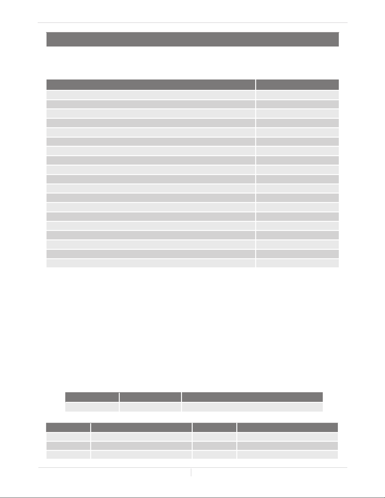
CENTROTHERM PP VENTING (Polypropylene)
WARNING! Do not mix parts or fittings of different material types, and do not mix pipe, fittings, or
joining methods from different manufacturers. Combustion exhaust can contain carbon monoxide and
must be properly vented outside. Breathing abnormal amounts of carbon monoxide can result in serious injury or death.
Description
4''/6'' (102 mm/152 mm) x 39" (990 mm) Concentric Wall
4'' (102 mm) Twin Pipe to 4''/6'' (102 mm/152 mm) Concentric Adaptor
4" (102 mm) x 87° Elbow
100 mm to 4" (102mm) Increaser
4" (102 mm) x 12" (305 mm) Vent Length
4" (102 mm) x 24" (610 mm) Vent Length
4'' (102 mm) x 36'' (914 mm) Vent Length
4" (102 mm)x 72" (1,829 mm) Vent Length
4" (102 mm) Horizontal Drain Tee
3''/5'' (76 mm/127 mm) x 13'' (330 mm) Concentric Wall Termination SS
3'' (76 mm) Twin Pipe to 3''/5'' (76 mm/127 mm) Concentric Adaptor
3" (76 mm) x 87 Elbow
3" (76 mm) x 12" (305 mm) Vent Length
3" (76 mm) x 24" (610 mm) Vent Length
3" (76 mm) x 36'' (914 mm) Vent Length
3" (76 mm) x 72'' (1,829 mm) Vent Length
100 mm to 4" (102 mm) Increaser
100 mm to 4" (102 mm) 110 mm
3" (76 mm) Horizontal Drain Tee
Centrotherm Part Number (Trade
Name InnoFlue)
ICWS4639
ICTC0446
ISEL0487
ISIA10004
ISVL041
ISVL042
ISVL043
ISVL046
ISHDT04
ICWS3513
ICTC0335
ISEL0387
ISVL031
ISVL032
ISVL033
ISVL036
ISIA10004
ISRA1003
ISHDT03
-Exhaust vent (Stainless steel vent)-
This is a Category IV appliance and must be vented accordingly. The vent system must be sealed airtight.
All seams and joints without gaskets must be sealed with high heat resistant silicone sealant or UL listed
aluminum adhesive tape having a minimum temperature rating of 160 °F. For best results, a vent system
should be as short and straight as possible.
The Indoor model is a Category IV appliance and must be vented accordingly with any 4 inch vent
approved for use with Category III/IV or Special BH type gas vent.
The manufacturer recommends the NovaVent (Z-Vent) line. However, the following are also UL listed
manufacturers: ProTech Systems Inc. (FasNSeal), Metal-Fab Inc., and Heat-Fab Inc. (Saf-T Vent).
Follow the vent pipe manufacturer’s instructions when installing the vent pipe.
The maximum length of exhaust vent piping must not exceed 100 ft (30.5 m) (deducting 5 ft (1.5
m) for each elbow used in the venting system). Do not use more than 5 elbows.
When the horizontal vent run exceeds 5 ft (1.5 m), support the vent run at 3 ft (0.9 m) intervals
with overhead hangers.
Diameter Max. No. of Elbows Max. Vertical and Horizontal (Total) Vent Length
4 in. (102 mm) 5 100 ft (30.5 m )
*For each elbow added, deduct 5 ft (1.5 m) from max. vent length.
No. of Elbows Max. Vertical or Horizontal Vent Length No. of Elbows Max. Vertical or Horizontal Vent Length
0 100 ft (30.5 m) 3 85 ft (25.9 m)
1 95 ft (29.0 m) 4 80 ft (24.4 m)
2 90 ft (27.4 m) 5 75 ft (22.9 m)
Excludes vent terminators, termination elbows, or rain caps.
22 Page
Page 23
WARNING
OFF
1 2 3 4 5 6 7 8 9 10
OFF
1 2 3 4 5 6 7 8 9 10
Installaon Manual
Installaon
-DIP switch settings for vent length-
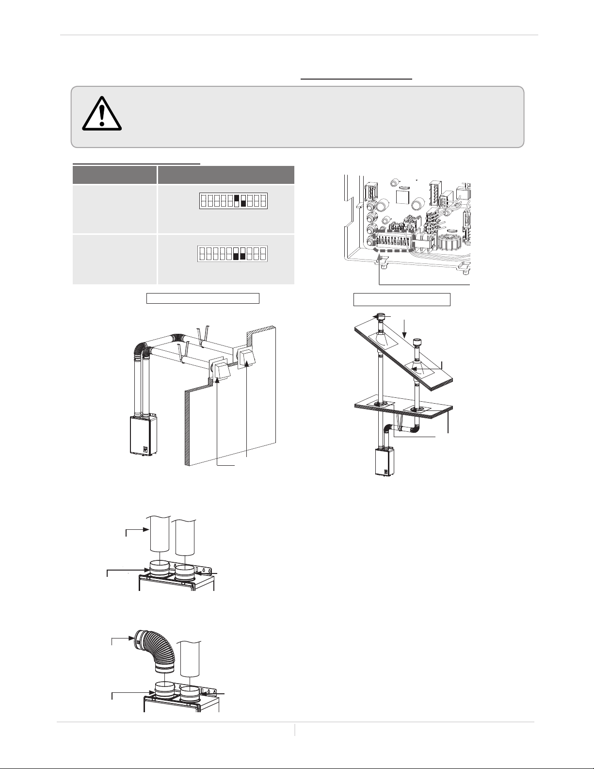
Typicalinstallaonsusingstainless steel vents
• Adjust the appropriate DIP switches according to size and vent length as shown
below. DO NOT adjust the other DIP switches.
• Turn off the power supply to the water heater before changing the DIP switch settings.
• Failure to observe these warnings could lead to carbon monoxide poisoning or death.
4inchventinstallaon
Vent length Two-pipe and Single pipe
5 to 50 ft
(1.5 to 15.2 m)
(DEFAULT)
51 to 100 ft
(15.3 to 30.5 m)
HorizontalInstallaon
ON
No. 6 : ON
No. 7 : OFF
ON
No. 6 : OFF
No. 7 : OFF
Hanger
Hanger
Wall
Computer board
Bank of DIP switches
VercalInstallaon
Rain cap
Roof
Fire stop
Intake vent collar
Intake vent collar
(Female)
For details of the optional items, refer to the Installation manual for each optional item.
4" stainless steel
vent straight pipe
(Female)
4" elbow with
bird screen
Sidewall vent
Ventconneconsfordirectvent
4" stainless steel
vent straight pipe
Exhaust vent
collar (Female)
Connect 4" stainless steel ventstraight pipes
directly on the exhaust/intake vent collar of the
water heater.
Ventconneconsforsinglevent
4" stainless steel
vent straight pipe
Exhaust vent
collar (Female)
1. Connect a 4" stainless steel vent straight pipes
directly on the exhaust vent collar of the water
heater.
2. Connect a 4" elbow directly on the intake vent
collar of the water heater.
23 Page
Page 24
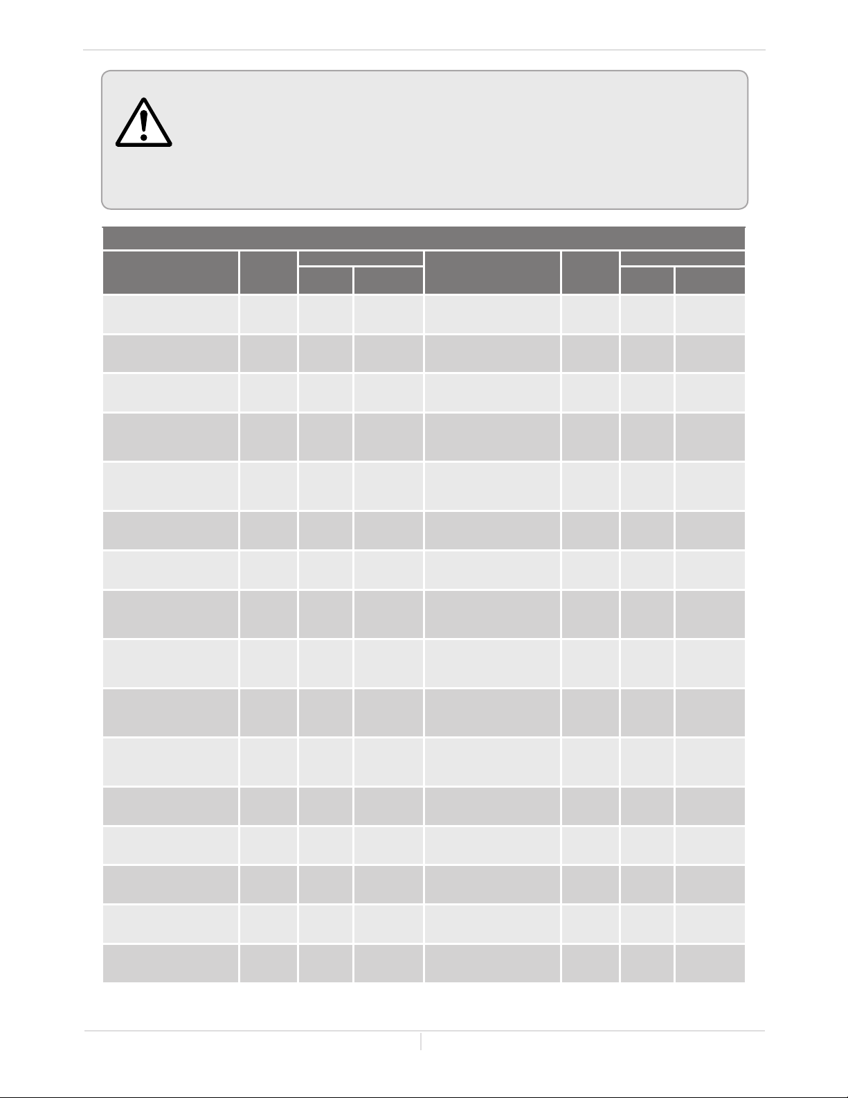
See pp. 25 to 27 regarding clearances from the exhaust terminal to the air inlet or opening.
Follow all vent system manufacturer’s instructions and all local codes.
Use 4" (102 mm) Category III/IV approved or Special BH, single or double wall stainless steel
WARNING
Description
4" (102 mm) Straight pipe
- 6" (152 mm) length
4" (102 mm) Straight pipe
- 12" (305 mm) length
Do not mix parts or fittings of different material types, and do not mix pipe, fittings, or
Installaon Manual
Installaon
vent pipe.
joining methods from different manufacturers. Combustion exhaust can contain carbon
monoxide and must be properly vented outside. Breathing abnormal amounts of carbon
monoxide can result in serious injury or death.
Approved Category IV, Single Wall, Venting Suppliers and Part Numbers
Heater
Vent
Kits
100112407 2NVP4.5 2SVEPWCF0406
100112406 2NVP41 2SVEPWCF0401 4" (102 mm) F-F adaptor 100112399 2NVAFF4 2SVEEWCF0445
Nova
VENT™
Z-FLEX®
Z-VENT™
Description
4" (102 mm) 3-in-1 adaptor
(F-F adaptor, condensate drain,
& back-flow preventer)
Heater
Vent
Kits
100112585 2NVBFA4 2SVBFDPA04
Nova
VENT™
Z-FLEX®
Z-VENT™
4" (102 mm) Straight pipe
- 24" (610 mm) length
4" (102 mm) Straight pipe
- 36" (914 mm) length
4" (102 mm)Straight pipe
- 48" (1,219 mm) length
4" (102 mm) Adjustable straight pipe -
10"-18" (254 - 457 mm)
adjustability
4" (102 mm) 45 degree elbow 100112401 2NVE445 2SVEEWCF0445
4" (102 mm) 90 degree elbow 100112400 2NVE490 2SVEEWCF0490
4" (102 mm) Sidewall termination
(4" (102 mm)Termination Hood)
4" (102 mm) Vent
termination tee
4" (102 mm) Rain Cap 100112415 2NVRC4 2SVSRCF04
4" (102 mm) Extreme weather
rain cap
100112404 2NVP42 2SVEPWCF0402
100112403 2NVP43 2SVEPWCF0403
100112402 2NVP44 2SVEPWCF0404
100112405 2NVAL4 2SVSPA04
100112419 2NVTH4 2SVSHTX04
100112547 2NVTT4 2SVSTTF04
100112548 2NVWC4 2SVSHRC04 4" (102 mm) Flat roof flashing 100112412 2NVFF4 2SVSSCF04
4" (102 mm) Backflow preventer
w/ F-F adaptor
4" (102 mm) exhaust / 3" (76 mm)
intake DV concentric termination
- 5"-10" (127 - 254 mm)
adjustability
4" (102 mm)exhaust / 3" (76 mm)
intake DV concentric termination
- 12"-18" (305 - 457 mm)
adjustability
4" (102 mm) Sidewall termina-
tion, adjustable pipe
4" (102 mm) Wall Thimble,
3"-6"(76 - 152 mm) wall thickness
4" (102 mm) exhaust / 3" (76 mm)
intake concentric termination
- 5" to 10" (127 - 254 mm)
adjustability
4" (102 mm) exhaust / 3" (76 mm)
intake concentric termination
- 12" to 18" (305 - 457 mm)
adjustability
4" (102 mm) exhaust / 4" (102
mm) intake concentric termination
- 5" to 10" (127 - 254 mm)
adjustability
4" (102 mm) exhaust / 4" (102
mm) intake concentric termination
- 12" to 18" (305 - 457 mm)
adjustability
100112416 2NVBFU4 2ZVB04
100112550 2NVHTC43S 2SVSHTC43S
100112551 2NVHTC43 2SVSHTC43
100187853 2NVBV4 n/a
100187852 2NVBT4 n/a
100112550 2NVHTC43S 2SVSHTC43S
100112551 2NVHTC43 2SVSHTC43
100112552 2NVHTC44S 2SVSHTC04S
100112553 2NVHTC44S 2SVSHTC04
4" (102 mm) Horizontal drain tee 100112414 2NVHD4 2SVEDWCF04 4" (102 mm) Angled roof flashing 100112411 2NVAF4 2SVSADJF04
4" (102 mm) Vertical drain tee 100112413 2NVVD4 2SVEVDP04 Storm collar 100112410 2NVSC4 2SVSLSF04
4" (102 mm) wall thimble length
4"-7" (102 - 178 mm)
wall thickness
4" (102 mm) wall thimble length
5"-10" (127 - 254 mm)
wall thickness
100112732 2NVWT4 2SVSWTF04 Wall support 100112409 2NVSS41 2SVSWS04
100112733 2NVWT4L 2SVSWTEF04 Firestop support 100112408 2NVFS4 2SVSFSSF04
24 Page
Page 25
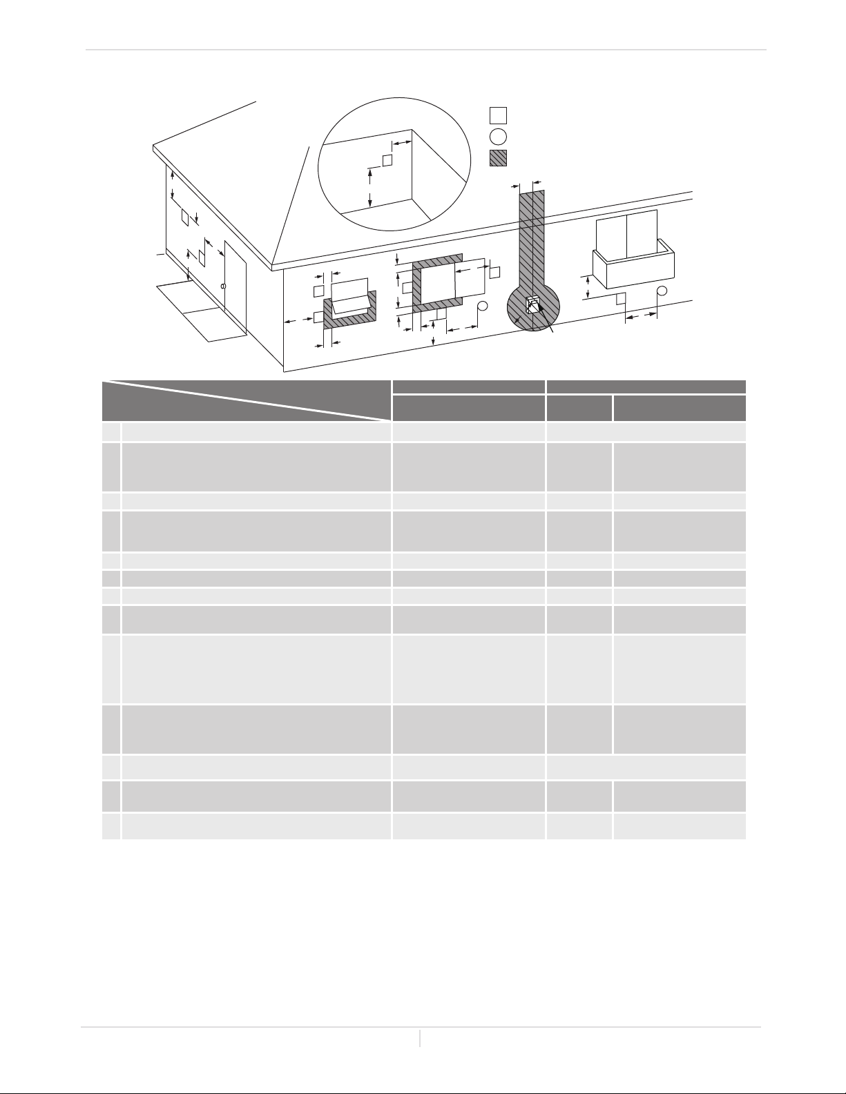
-Vent terminaon clearances-
Installaon Manual
Installaon
Inside corner
detail
G
V
D
E
V
B
V
L
C
V
V
F
B
Fixed
closed
Operable
A
B
Operable
V
B
V
B
A
Canada Installations
Direct vent and other than
direct vent
Fixed
closed
J
V
= Vent terminal
X
= Air supply inlet
= Area where the terminal
is not permied
H
B
V
X
I
1
M
V
K
Regulator/Gas meter
vent outlet
US Installations
Direct vent
X
2
Other than
direct vent
A Clearance above grade, veranda, porch, deck, or balcony 1 ft (30 cm) 1 ft (30 cm)
B Clearance to window or door that may be opened 3 ft (91 cm)
1 ft
(30 cm)
4 ft (1.2 m) below or to
side of opening; 1 ft (30
cm) above opening
C Clearance to permanently closed window 0 0 0
Vertical clearance to ventilated soffit located above
D
the vent terminator within a horizontal distance of 2
3 ft (91 cm) 3 ft (91 cm) 3 ft (91 cm)
feet (61cm) from the center line of the termination
E Clearance to unventilated soffit 3 ft (91 cm) 3 ft (91 cm) 3 ft (91 cm)
F Clearance to outside corner 2 ft (61 cm) 2 ft (61 cm) 2 ft (61 cm)
G Clearance to inside corner 2 ft (61 cm) 2 ft (61 cm) 2 ft (61 cm)
Clearance to each side of center line extended
H
above meter/regulator assembly
3 ft (91 cm) * *
Above a regulator within 3
ft (91 cm) horizontally of the
I Clearance to service regulator vent outlet
vertical center line of the
regulator vent outlet to a
* *
maximum vertical distance of
15 ft (4.5 m)
Clearance to non-mechanical air supply inlet to
J
building or the combustion air inlet to any other
3 ft (91 cm)
appliance.
K Clearance to mechanical air supply inlet 6 ft (183 cm)
Clearance above paved sidewalk or paved driveway
L
located on public property
7 ft (213 cm)**
M Clearance under veranda, porch deck, or balcony 1 ft (30 cm)***
1 ft
(30 cm)
3 ft (91 cm) above if within
7 ft
(213 cm)
1 ft
(30 cm)***
4 ft (1.2 m) below or to
side of opening; 1 ft (30
cm) above opening
10 ft (3 m) horizontally.
7 ft (213 cm)
1 ft (30 cm)***
*Clearance in accordance with local installation codes and the requirements of the gas supplier.
**A vent shall not terminate directly above a sidewalk or paved driveway that is located between two single family dwellings
and serves both dwellings.
***Permitted only if veranda, porch, deck, or balcony is fully open on a minimum of two sides beneath the floor.
The vent for condensing water heaters shall not terminate:
1) over public walkways; or
2) near soffit vents or crawl space vents or other areas where condensate or vapor could create a nuisance or hazard or
cause property damage; or
3) where condensate vapor could cause damage or could be detrimental to the operation of regulators, relief valves, or
other equipment.
Notes:
1) In accordance with the current CSA B149.1, Natural Gas and Propane Installation Code
2) In accordance with the current ANSI Z223.1/NFPA 54, National Fuel Gas Code
25 Page
Page 26
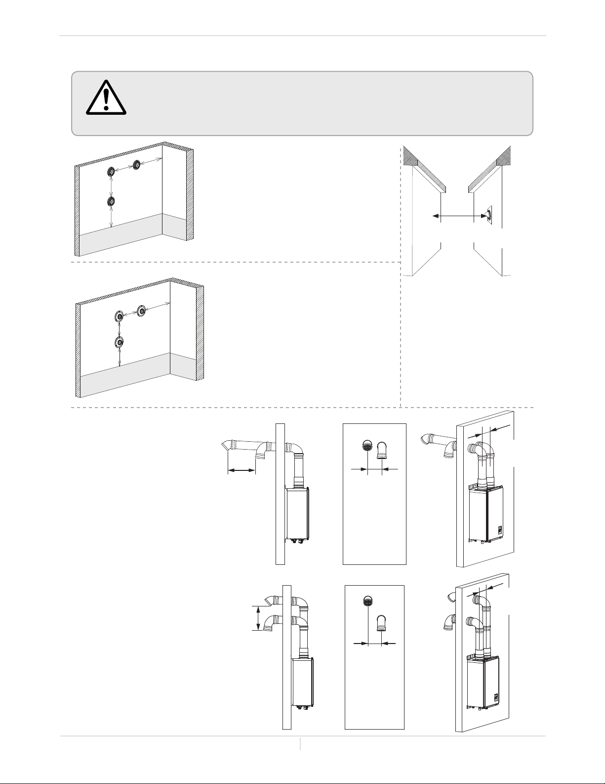
WARNING
1
(305 mm)
Exhaust
Terminaon
Ancipated Snow level
Combined
intake and
terminaon
min.
1
(305 mm)
min.
exhaust
Ancipated Snow level
1
(305 mm)
min.
1
(305 mm)
min.
Installaon Manual
Installaon
-Clearances for sidewall terminaons-
Improper installation can result in carbon monoxide poisoning or death. Follow all local
and national codes in regards to proper termination clearances. In the absence of such
codes, the clearances below can be used as guidelines. Local codes supersede these
guidelines.
Multiple Sidewall Terminations
2
(610 mm)
min.
(610 mm)
min.
Inside
corner
2
Inside
corner
An exhaust termination must be at least
1 ft (305mm) away from another exhaust
termination. An exhaust termination must
also be at least 2 ft (610 mm) away from
an inside corner. (If the adjacent wall is less
than 2 ft (610 mm) of length, the minimum
required distance away from the inside
corner will be equal to the length of that
adjacent wall.)
Multiple DV Sidewall Terminations
A direct vent (DV) termination must be
at least 1 ft (305 mm) away from other
direct vent terminations.
A direct vent termination must also be at
least 2 ft (610 mm) away from an inside
corner. (If the adjacent wall is less than
2 ft (610 mm) of length, the minimum
required distance away from the inside
corner will be equal to the length of that
adjacent wall.)
2 ft (610 mm)
min.
Exhaust
termination
Exhaust and/or direct
vent sidewall terminations
should be at least 2 ft (610
mm) away from an opposite
surface/wall. Do not place
the termination directly in
front of an opening into a
building.
<Case 1>
For direct vent sidewall
terminations that use two
separate penetrations for
the intake and exhaust, keep
the termination clearances
shown in the diagrams on
the right. The installation is
for only 3 inch and 4 inch
vent installations only.
<Case 2>
Exhaust
1 (305 mm)
min.
1
(305 mm)
min.
Intake
Exhaust
Intake
Exhaust
(159 mm)
Exhaust
(159 mm)
0.5 ft
min.
Intake
0.5 ft
min.
Intake
0.5 ft
(159 mm)
min.
0.5 ft
(159 mm)
min.
26 Page
Page 27
WARNING
NOTICE
Installaon Manual
Installaon
-Clearances for rooop terminaons-
Follow all local and national codes in regards to proper termination clearances. In the absence
of such codes, the clearances below must be met. Local codes supersede these clearances.
Failure to observe this warning may result in severe personal injury or death.
Canadian requirements differ from the guidelines in this section. In Canada, follow
the requirements of B149.1 (Natural Gas and Propane Installation Code, current
edition) as well as local and provincial codes. Contact your local code enforcement
agency for direction.
Angled roof termination
2 ft (610 mm) min.
Intake air
1 ft
(305 mm) min.
Multiple angled roof terminations
Intake air
1
(305 mm)
min.
1
(305 mm)
min.
Intake air
2 (610 mm) min.
Exhaust gas
3 (914 mm) min.
Exhaust
gas
1
(305 mm)
min.
1
(305 mm)
min.
1 ft
(305 mm) min.
1 ft
(305 mm) min.
Anticipated
snow level
Exhaust
gas
1
(305 mm)
min.
1 ft
(305 mm) min.
Vercal wall
1
(305 mm)
min.
Ancipated snow level
Flat roof termination
3 ft (914 mm) min.
Intake air
Exhaust gas
1 ft
(305 mm) min.
Multiple flat roof terminations
2
2
(610 mm)
min.
Intake air
(610 mm)
min.
1
(305 mm)
min.
Intake air
Exhaust gas
1
(305 mm)
min.
3 (914 mm) min.
Anticipated
snow level
Exhaust gas
1
(305 mm)
min.
1
(305 mm)
min.
1
(305 mm)
min.
WARNING
Ancipated snow level
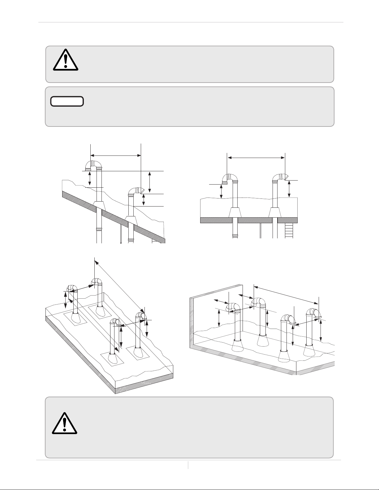
Exhaust terminations must be at least 1 ft (305 mm) away from any obstructions.
Minimum spacing between multiple terminals:
intake terminals: 1 ft (305 mm) spacing between each
exhaust terminals: 1 ft (305 mm) spacing between each
The exhaust termination must be a horizontal distance of at least 2 ft (610 mm) from a
wall or surface unless specified differently by local code.
Failure to observe this warning may result in severe personal injury or death.
27 Page
Page 28
GAS SUPPLY AND GAS PIPE SIZING
-General-
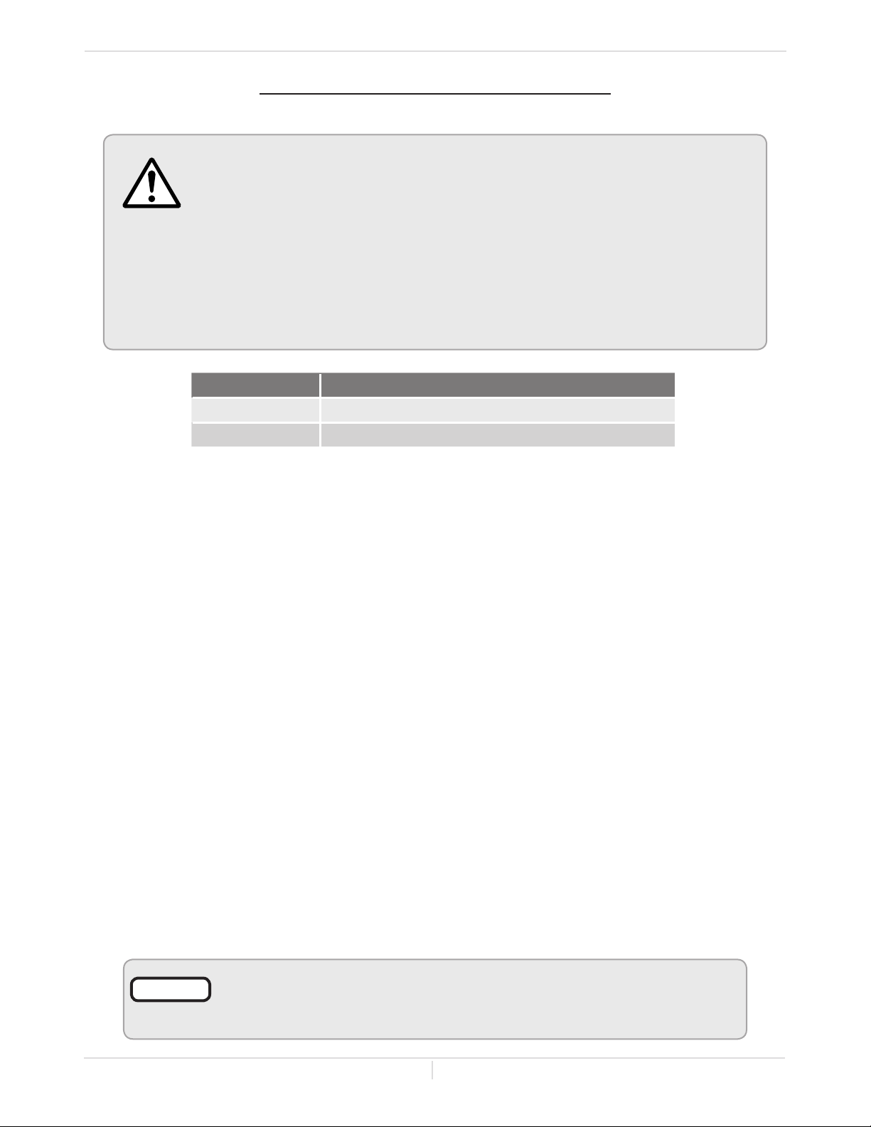
Do not use this water heater with any gas other than the one listed on the rating
plate.
Ensure that any and all gas regulators used are operating properly and providing gas
pressures within the specified range shown below. Excess gas inlet pressure may
WARNING
The minimum and maximum inlet gas pressures are:
cause serious accidents.
Conversion of this unit from natural gas to propane or vice versa will void all
warranty. Contact your local distributor to get the correct unit for your gas type. The
manufacturer is not liable for any property and/or personal damage resulting from
gas conversions.
Failure to observe these warnings could result in severe personal injury, carbon
monoxide poisoning, or death.
Gas type Inlet gas pressure
Natural Gas Min. 4.0” W.C. (1.00 kPa) – Max. 10.5” W.C. (2.61 kPa)
Propane Min. 8.0” W.C. (1.99 kPa) – Max. 14.0” W.C. (3.48 kPa)
Installaon Manual
Installaon
Inlet gas pressures that fall outside the range of values listed above may adversely affect the
performance of the water heater. These pressures are measured when the water heater is in full
operation and in standby.
Inlet gas pressure must not exceed the above maximum values; gas pressure above the specified range
will cause dangerous operating conditions and damage to the unit.
Until testing of the main gas line supply pressure is completed, ensure the gas line to the water heater
is disconnected to avoid any damage to the water heater.
If the gas supply pressure to the heater is greater than the specified maximum, a field-supplied
regulator is required. The regulator must lower the gas pressure within the approved range.
Install the gas regulator according to the manufacturer's instructions.
The regulator must be sized for the water heater input and provide the specified pressures that are
listed on the rating plate.
In the absence of minimum install distance, it is recommended that there is at least 3 ft (1 m) of piping
between the regulator outlet and the water heater's inlet gas connection.
-Gas connecons-
1. Install a manual gas shutoff valve between the water heater and the gas supply line.
2. When the gas connections are completed, it is necessary to perform a gas leak test either by applying
soapy water to all gas fittings and observing for bubbles or by using a gas leak detection device.
The water heater and its individual shutoff valve must be disconnected from the gas supply
piping system during any pressure testing of that system at test pressures in excess of 1/2 psi
(3.5 kPa).
The water heater must be isolated from the gas supply piping system by closing its individual
manual shutoff valve during any pressure testing of the gas supply piping system at test
pressures equal to or less than 1/2 psi (3.5 kPa).
3. Always purge the gas line of any debris and/or water before connecting to the gas inlet.
NOTICE
Size the gas pipe appropriately to supply the necessary volume of gas required for
the water heater using ANSI Z223.1/NFPA 54 in the USA or B149.1 in Canada or
local codes. Otherwise, flow capabilities and output temperatures will be limited.
28 Page
Page 29
Installaon Manual
Installaon
-Natural gas supply piping-
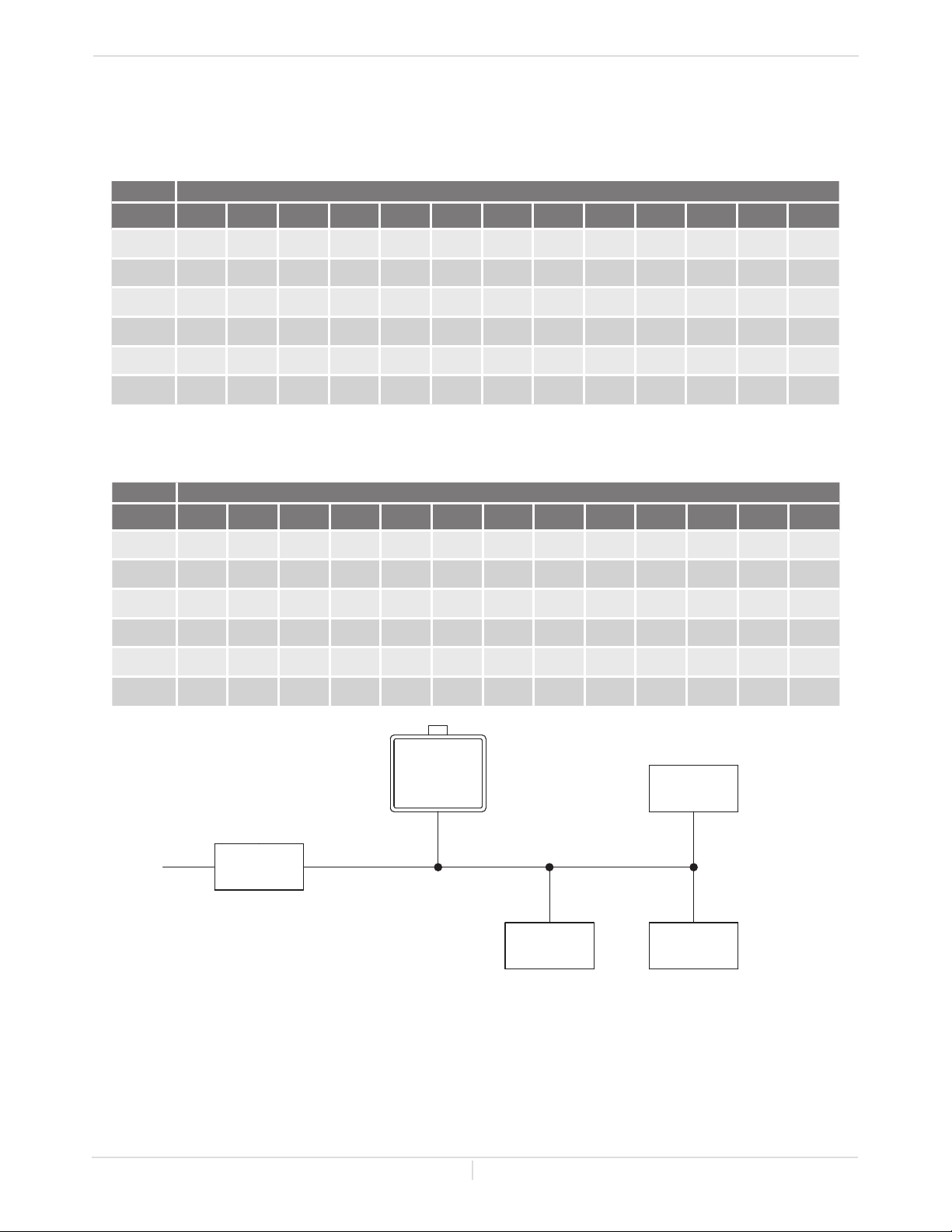
Maximum delivery Capacity in Cubic Feet of Gas per Hour (based on IPS Pipe carrying Natural Gas with 0.60 Specific
Gravity with a Pressure Drop of 0.5" W.C.).
Based on Energy Content of 1,000 BTU/Cubic ft: The water heater requires 120 Cubic ft/hr for the 140 model.
The following tables are from NFPA 54.
Pipe Size
Diameter
1/2"
(13 mm)
3/4"
(19 mm)
1"
(25mm)
1/4"
1
(32mm)
1/2"
1
(38mm)
2"
(51mm)
10'
(3 .0 m)
172 118 95 81 72 65 60 56 52 50 44 40 34
360 247 199 170 151 137 126 117 110 104 92 83 71
678 466 374 320 284 257 237 220 207 195 173 157 134
1,390 957 768 657 583 528 486 452 424 400 355 322 275
2,090 1,430 1,150 985 873 791 728 677 635 600 532 482 412
4,020 2,760 2,220 1,900 1,680 1,520 1,400 1,300 1,220 1,160 1,020 928 794
20'
(6.1 m)
30'
(9.1 m)
40'
(12.2 m)
50'
(15.2 m)
60'
(18.3 m)
Length
70'
(21.3 m)
80'
(24.4 m)
90'
(27.4 m)
Unit: Cubic feet per hour
100'
(30.5 m)
125'
(38.1 m)
150'
(45.7 m)
200'
(61.0 m)
-Propane (LP) supply piping-
Maximum Capacity of Propane (LP) Based on 11" W.C. supply pressure at a 0.5" W.C. pressure drop
Pipe Size
Diameter
1/2"
(13 mm)
3/4"
(19 mm)
1"
(25mm)
1/4"
1
(32mm)
1/2"
1
(38mm)
2"
(51mm)
10'
(3 .0 m)
20'
(6.1 m)
30'
(9.1 m)
40'
(12.2 m)
50'
(15.2 m)
(18.3 m)
268 184 148 126 112 101 93 87 82 77 68 62 53
567 393 315 267 237 217 196 185 173 162 146 132 112
1,071 732 590 504 448 409 378 346 322 307 275 252 213
2,205 1,496 1,212 1,039 913 834 771 724 677 630 567 511 440
3,307 2,299 1,858 1,559 1,417 1,275 1,181 1,086 1,023 976 866 787 675
6,221 4,331 3,465 2,992 2,646 2,394 2,205 2,047 1,921 1,811 1,606 1,496 1,260
60'
Length
70'
(21.3 m)
80'
(24.4 m)
90'
(27.4 m)
100'
(30.5 m)
Unit: kBTU per hour
125'
(38.1 m)
150'
(45.7 m)
200'
(61.0 m)
Gas sizing example
(Natural Gas)
10' Length
Gas meter
Based on Energy Content of 1,000 BTU/Cubic ft:
Divide each appliance's BTU/h requirement by 1,000 BTU/ft3 to get the appliance's ft3/h requirement.
Take into account the distance the appliance is from the gas meter, look in the above gas chart to properly size the line.
For sections of the gas line supplying gas to more than one appliance (Ex: Point A to Point B), add up the cubic ft per hour
requirements of the appliances that are being supplied by that section, and size to the farthest appliance.
For Example: The section from A to B supplies gas to the furnace, range and dryer. Adding up the BTU/h requirements and
dividing by 1,000 yields a cubic ft per hour requirement of 220 cubic ft of gas per hour. The farthest appliance is the range, which
is 50 ft away from the meter. Looking at the above chart, and under the column of 50 ft, Section A to B needs to be 1" in order
to supply 220 cubic ft.
1-1/4" Pipe size
Water
heater
120,000 BTU/h
10' Length
1/2" Pipe size
A
1" Pipe size
10' Length
120,000 BTU/h
B
10' Length
3/4" Pipe size
Furnace
15' Length
1" Pipe size
Dryer
35,000 BTU/h
10' Length
1/2" Pipe size
15' Length
1/2" Pipe size
C
Range
65,000 BTU/h
29 Page
Page 30
WARNING
Installaon Manual
Installaon
WATER CONNECTIONS
Do not use this appliance if any part has been under water. Immediately contact
a qualified installer or service agency to replace a flooded water heater. Do not
attempt to repair the unit! It must be replaced!
NOTICE
All pipes, pipe fittings, valves and other components, including soldering materials, must be suitable for
potable water systems.
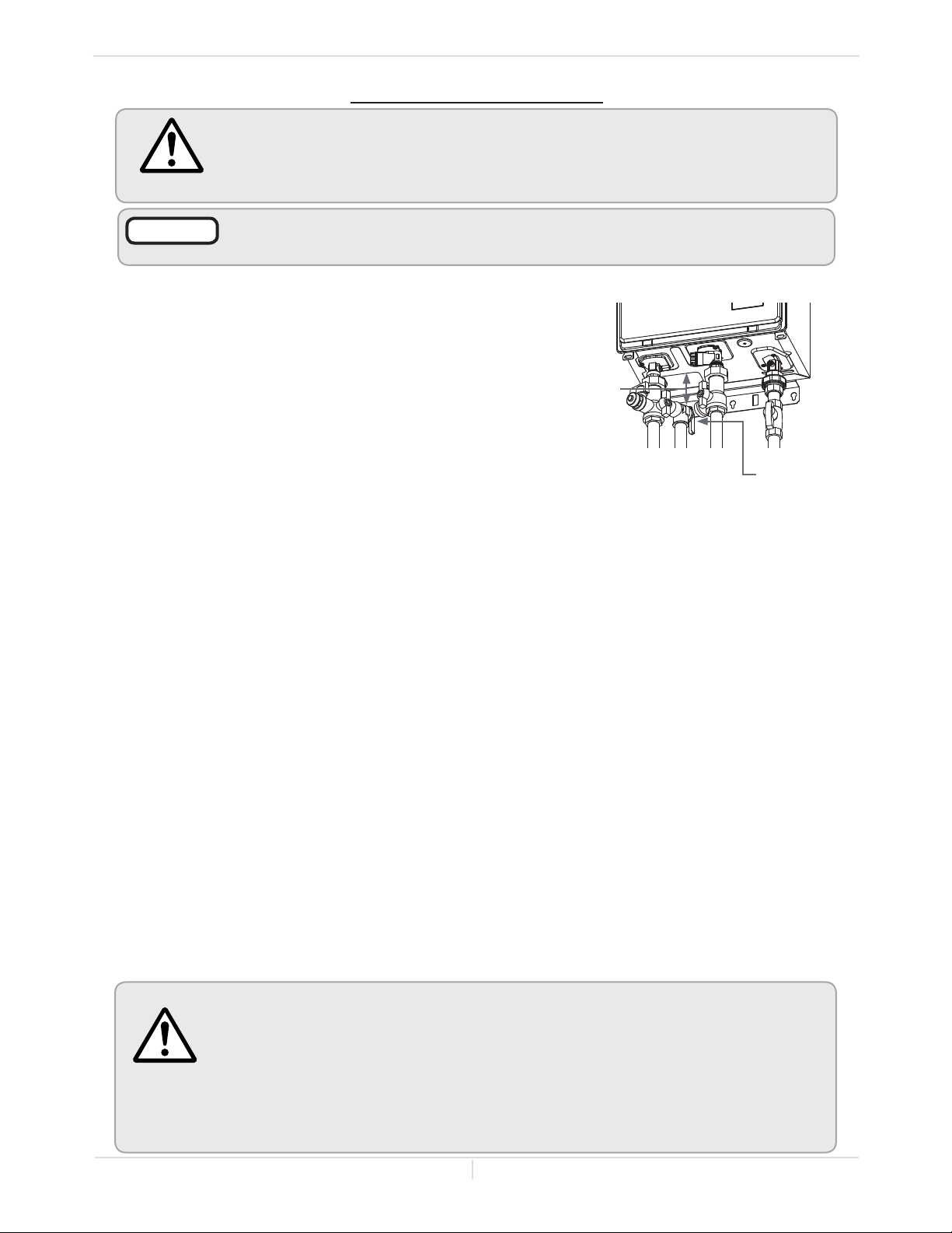
1. A manual shutoff valve must be installed on the cold
water inlet to the water heater between the main
water supply line and the water heater.
2. In addition, a manual shutoff valve is also recommended on the hot water outlet of the unit. If the water
heater is installed within, or subjected to, a closed
loop water system, a thermal expansion tank
or code approved device to handle thermal expansion
must be installed.
3. Before installing the water heater, flush the water line to remove all debris, and after installation is
complete, purge the air from the line. Failure to do so may cause damage to the heater.
4. There is a wire mesh filter within the cold inlet to trap debris from entering your heater. This will need
to be cleaned periodically to maintain optimum flow. (Refer to p. 56.)
Do not reverse the hot outlet and cold inlet connections to the water heater. This will
prevent the water heater from activating properly.
As Close as
Possible
Hot
outlet
Cold
inlet
Gas inlet
Pressure
relief valve
-Pressure relief valve-
The water heater has a high-temperature shutoff switch built in as a standard safety feature (called a
Hi-Limit switch) therefore a “pressure only” relief valve is required.
This unit does not come with an approved pressure relief valve.
An approved pressure relief valve must be installed on the hot water outlet.
The pressure relief valve must conform to ANSI Z21.22 or CAN 1-4.4 and installation must follow local codes.
The discharge capacity must be at least 120,000 BTU/h for the 140 model.
The pressure relief valve needs to be rated for a maximum of 150 psi (1 MPa).
The discharge piping for the pressure relief valve must be directed so that the hot water cannot splash
outward and cause damage or personal injury.
Attach the discharge tube to the pressure relief valve and run the end of the tube to within 6 in
(152 mm) from the floor. This discharge tube must allow free and complete drainage without any
restrictions.
If the pressure relief valve discharges periodically, this may be due to thermal expansion in a closed
water supply system. Contact the water supplier or a local plumbing professional on how to correct
this situation. Do not plug the pressure relief valve.
The pressure relief valve must be manually operated periodically to check for correct operation.
Before operating the valve manually, check that it will discharge in a place for secure disposal.
No valve must be placed between the relief valve and the water heater.
WARNING
Hot water could be released when the pressure relief valve is opened. This
could result in severe personal injury. Before operating the pressure relief
valve manually, check that it will discharge in a safe place. If water does not
flow freely from the end of the discharge pipe, turn the gas supply and power
OFF and call a qualified person to determine the cause.
Refer to the pressure relief valve manufacturer's instructions for inspection
and maintenance requirements.
30 Page
Page 31
Installaon Manual
Installaon
CONDENSATE DRAIN
The water heater does not include a built-in condensate neutralizer cartridge for reducing the pH level
of condensate water. If local codes dictate that condensate must be neutralized prior to drainage, a
condensate neutralizer must be installed. An accessory Neutralizer assembly (100112159/TH-NT01)
is sold separately. (Refer to p. 10.)
In the absence of applicable local codes and regulations, the manufacturer recommends that
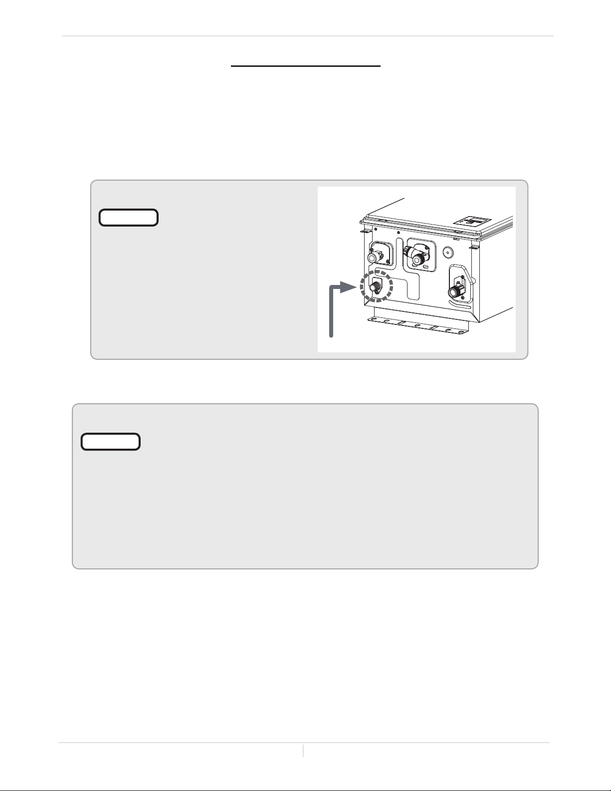
condensate be disposed of into a drain. Connect a drain tube from the condensate drain port (shown
below) located on the bottom of the water heater to a standard drain.
NOTICE
NOTICE
Follow all code requirements
of the local authority for
condensate neutralizers and
whether or not they are required
for the installation.
Condensate drain port
-Condensate drain connecons-
• Discharge condensate (acidic water) in accordance with all local codes and common safety practices.
• Use corrosion resistant pipe, such as PVC, for the condensate drain line.
Do not use metal pipe.
• The condensate drain does not require a trap.
• Maintain a downward slope on the drain line(s), including installations in which
the drain is not directly below the water heater.
• A field-supplied bypass is required if a neutralizer is installed.
• Do not connect the condensate drain line directly to a condensate pump.
• If the drain line is required to have bends, ensure that there are no kinks that
will restrict the flow of condensation.
The water heater is a high efficiency condensing water heater that produces condensate (acidic water).
The acidic condensate generated in the secondary heat exchanger can be neutralized by the neutralizer
accessory (100112159/TH-NT01).
Although a neutralizer is not required, a condensate drain must be installed as described on the next page.
31 Page
Page 32
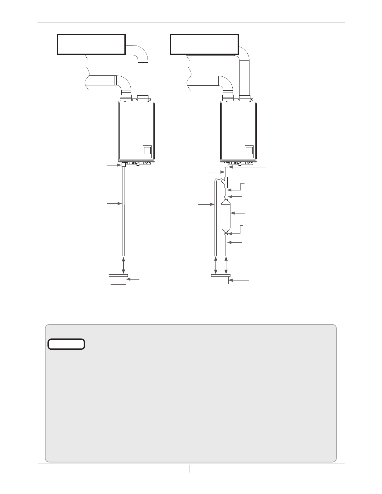
Installaon Manual
Installaon
Installation
without neutralizer
3/8" MPT x 3/8"
(or 1/2") HB*
1/2"
Condensate
drain tube**
Installation
with neutralizer
1/2"
Condensate
drain tube**
Overflow bypass**
(1/2" Condensate
drain tube)
3/8" MPT x 3/8"
(or 1/2") HB*
1/2" Condensate drain tube**
1/2" MPT x 3/8" FPT (Included
with Neutralizer accessory)
Neutralizer cartridge (Included
with Neutralizer accessory)
1/2" FPT x 1/2" HB (Included
with Neutralizer accessory)
1/2" Condensate drain tube**
2" (50 mm)
MIN. distance***
Floor drain, standpipe,
or other acceptable drain
*Connect to the condensate drain port. (Refer to p.31.)
**Maintain downward slope, including installations in which the drain is not directly below the heater.
***A 2" (50 mm) minimum distance must be maintained between the condensate line and drain to allow
full flow of the condensation.
The condensate drain is at atmospheric pressure (non-pressurized) and therefore must
be allowed to drain freely with gravity only. Ensure that the condensate drain tube is
NOTICE
not plugged or blocked, and ensure that it slopes downward to allow condensate to
flow freely. All portions of the condensate drain (neutralizer and drain tube) must
be at a lower elevation than the water heater to prevent condensate water from
building up inside the heat exchanger.
Condensate cannot be effectively neutralized if the neutralizer elements inside the
Neutralizer accessory have been completely consumed. If this happens, condensate
will remain acidic and can possibly cause damage to items such as pipes, concrete,
etc., if drained improperly.
The actual life of the neutralizer may vary, depending on the application and usage.
Replace the cartridge when the condensate pH goes below 6.0.
Please ensure that the cartridge is properly replaced before the neutralizer elements
have been completely consumed.
All preventative measures and safety practices must be adhered to when draining condensate.
The manufacturer will not be responsible for any damage caused by condensate.
A drain pan, or other means of protection against water damage, is recommended to
be installed under the water heater in case of leaks.
2" (50 mm)
MIN. distance***
2" (50 mm)
MIN. distance***
Floor drain, standpipe,
or other acceptable drain
32 Page
Page 33
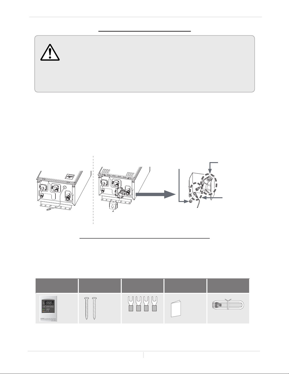
Installaon Manual
Installaon
ELECTRICAL CONNECTIONS
Ensure that circuit power is turned OFF before you complete the following steps.
Follow the electrical code requirements of the local authority having jurisdiction.
In the absence of such requirements, follow the current edition of the National
Electrical Code ANSI/NFPA 70 in the U.S. or the current edition of CSA C22.1 Canadian
WARNING
Indoor model comes with a power plug instead of a junction box. The following procedure is for the
outdoor model only.
1. The water heater must be electrically grounded. Do not attach the ground wire to either the gas or
the water piping.
2. The water heater requires a 120 VAC, 60 Hz electrical power supply that is properly grounded.
A proper disconnect (i.e. on/off switch, power plug, etc.) controlling the main power to the water
heater must be provided for service reasons. (Must comply with local codes.)
Connect the power supply to the water heater exactly as shown in the wiring diagram.
3. A green screw is provided in the junction box to ground the connection.
4. Can be hardwired or wired to a plug-in.
5. The use of a surge protector is recommended in order to protect the water heater from power surges.
Electrical Code Part 1 in Canada.
When servicing or replacing parts within the water heater, label all wires prior to
disconnection to facilitate an easy and error-free reconnection. Wiring errors can
cause improper and dangerous operation. Verify proper operation after servicing.
Failure to observe these warnings could result in personal injury or loss of life.
Indoor model
Outdoor model
Green screw
Connect
Power supply
120VAC, 60Hz
Ground
View of electrical
TEMPERATURE REMOTE CONTROLLER
-Included accessories-Outdoor model only
• The remote control is an optional accessory that can be installed in a hall, closet, etc., to allow for
temperature adjustment without having to go to the heater.
• When installed, the remote will take priority over the built-in controller of indoor model.
Verify that the items listed below are included with the remote controller.
Temperature
remote controller
Screws Fork terminals Manual
Remote controller
cable*
Qty: 1
100209924 (TM-RE42)
It is also an optional accessory as a second remote for the indoor model. Refer to pp. 9 and 10.
*The optional remote controller (sold separately) has no remote controller cable.
Qty: 2
Qty: 4
Qty: 1
Qty: 1
33 Page
Page 34
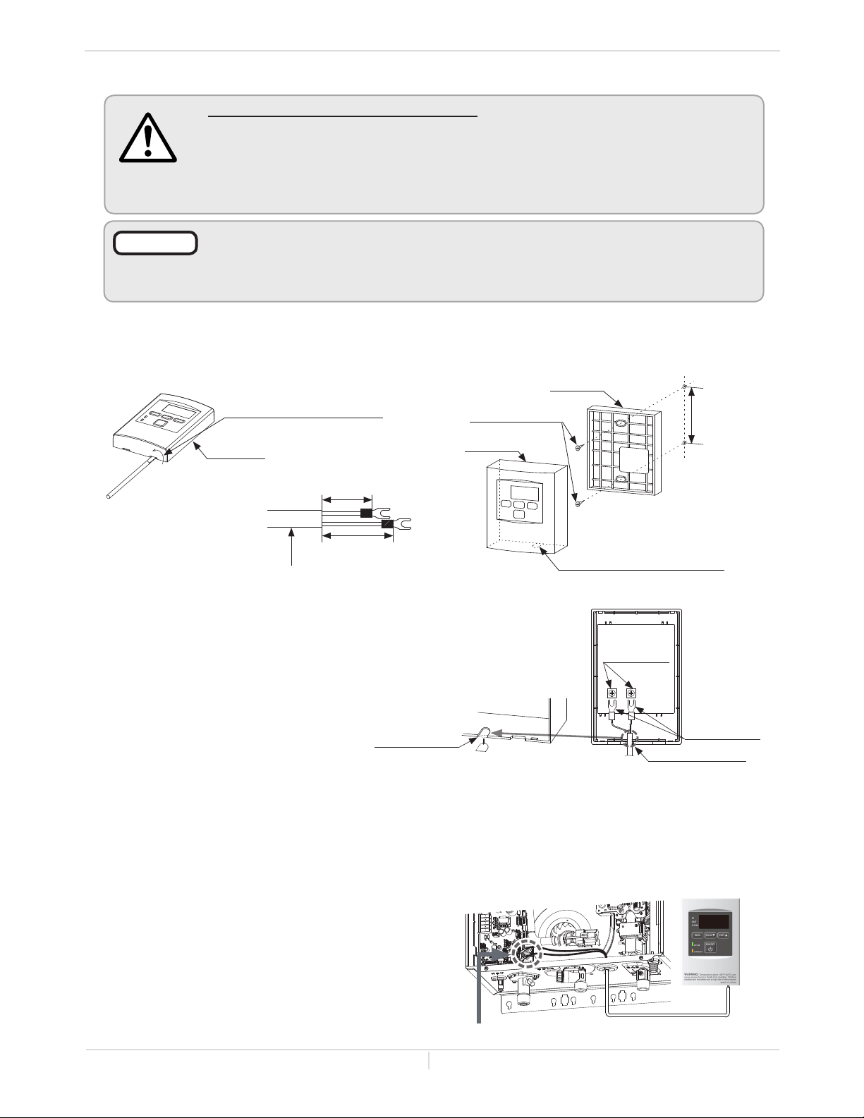
WARNING
Installaon Manual
Installaon
-Installaon-
This remote controller is NOT waterproof.
The water heater can only have one remote controller.
Do not install in high temperature environments, high humidity conditions outdoors, in
direct sunlight, or within the reach of children.
Make sure the remote controller does not come into contact with water or oil.
Failure to observe these warnings could result in personal injury or electrical shock.
NOTICE
Cables used for the remote controller connection must be:
Minimum 20 gauge wire (No polarity)
Maximum 400 ft (122 m) long
<Mounting and Wiring the Remote Controller>
Take off the Back plate from the remote controller with a flat head screwdriver. (Fig. A and B)
1.
Attach the Back plate on the wall with the two provided screws. (Fig. B)
2.
If you use another cable, crimp the Fork terminals to the wires. (Fig. C)
3.
Do not place the remote controller cable close to other wires from other products.
Fig. A
Twist
Tighten the two Fork terminals beneath the two Remote controller
4.
terminal screws on the back of the main body. (Fig. D-1)
Cut out the inlet for the remote controller cable from the bottom of the
5.
main body. (Fig. D-2)
Place the Main body back on the Back plate, with the Remote controller
6.
cable running out of the bottom inlet.
Press and twist flat head
screwdriver against the cutout.
Main body
Fig. C
Remote controller cable
1-3/8 Inch
(35 mm)
1-5/8 Inch
(41 mm)
Terminals
Fork
Fig. B
Attach the screws
Main body
Fig. D-2
Back plate
3-1/4 inches
Cut out the partition with pliers.
(removed during later steps.)
Fig. D-1
Remote controller
terminals
Inlet for the remote
controller cable
Cut out
<How to connect the remote controller to the water heater>
Disconnect power supply from the water heater.
1.
Take off the water heater’s front cover.
2.
Locate the two terminals for the remote controller in the water heater. (Refer to the Fig. E-1.)
3.
Take off the back plate from the remote controller, and then attach the two fork terminals to the
4.
connector base on the back side of the remote controller with two screws. Make sure the terminals are
firmly fixed. (See the above instructions for installation
of the remote controller.)
Pull the remote controller cable through the hole at
5.
Fig. E-1
the bottom of the water heater’s casing.
Secure both controller cable terminals to the
6.
terminals on the computer board as shown below.
(Secure them underneath the screw terminals. No
polarity.)
* Do NOT jump or short-circuit the cables, or
computer will be damaged.
Replace the front cover securely.
7.
Connect other end to these terminals
34 Page
Two fork terminals
Remote controller cable
100209924
(TM-RE42)
Page 35
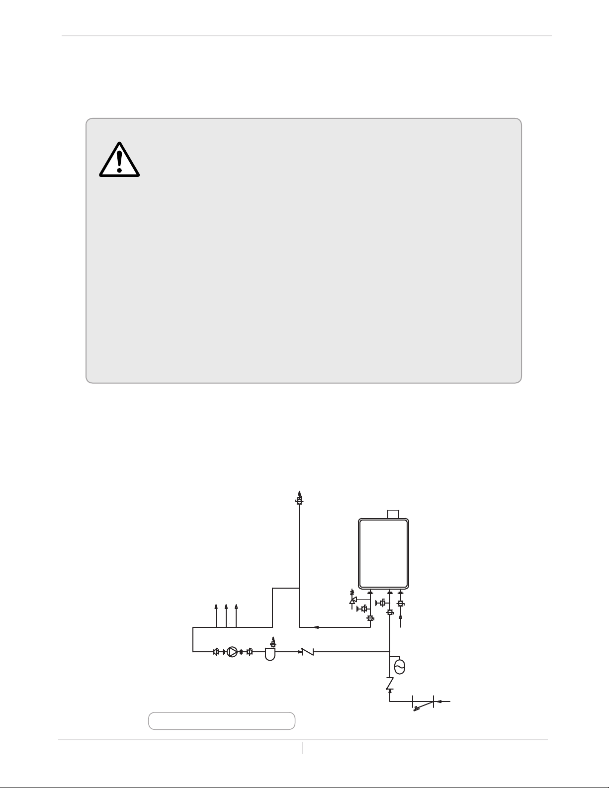
APPLICATIONS
This water heater is suitable for combination water (potable) heating and
space heating and not suitable for space heating applications only.
In order to purge air in water pipes within a closed-loop system, an air vent
and air separator should be installed in the system. Required circulation
WARNING
flow rates are labeled next to each application diagram. These flow rate
requirements must be followed.
Toxic chemicals used in boiler treatments such as alcohol, glycerol and glycol
groups must not be introduced into the system if the system incorporates an
open-loop potable water system.
The water heater can be used to supply potable water and space heating and
shall not be connected to any heating system or component(s) previously
used with non-potable water where any chemicals were added to the water
heating appliances.
When the system requires water for space heating at temperatures higher
than required for other uses, a means such as a mixing valve shall be installed
to temper the water for those other uses in order to reduce scald hazard
potential.
Water temperature over 125 °F (52 °C) can cause severe burns instantly or
death from scalding.
Installaon Manual
Installaon
-Space-Heang Applicaons-
-Recirculaon-
*The recirculation pump is to be controlled by:
-Dual-set aquastat (recommended w/timer)
*The recirculation pump is to provide no less than 2 GPM (7.5 L/min) and no more than 4 GPM (15 L/min) through
each activated unit in the system.
Air vent
Hot water outlet
Cold water inlet
Gas inlet
pump
S
Air
separator
Check valve
Check valve
Unions
Ball valves
Gas supply
Expansion tank
This is a concept drawing only.
Cold water inlet
Y-Strainer
35 Page
Page 36
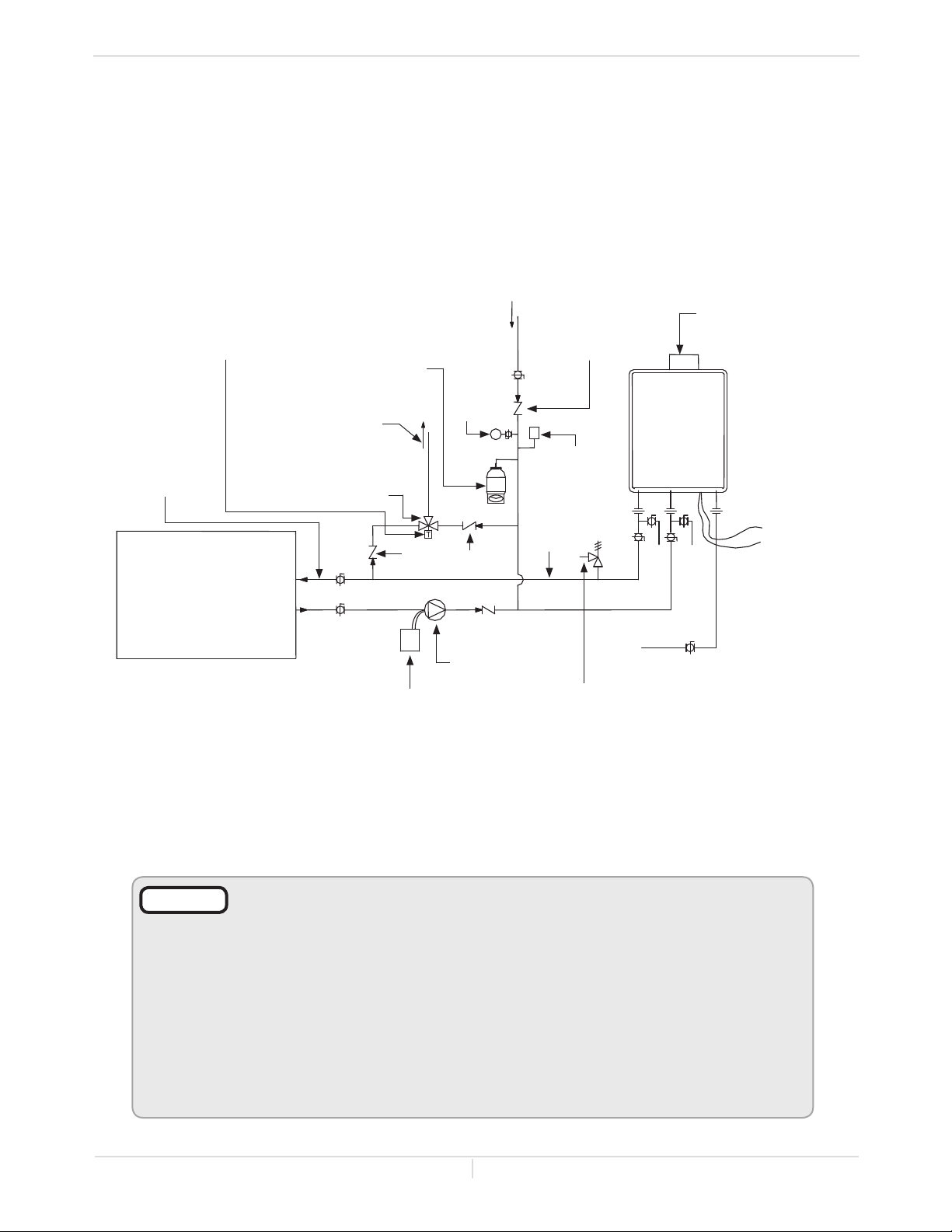
-Dual-purpose hot water heang-
(Domestic and Space Heating):
Diagrammatic layout of radiant heating and domestic water heater.
All water piping should be insulated
in accordance with 780 CMR
must be installed below
the top of the water heater
as per manufacturer’s
Piping loop
between water
heater and fan
coil shall be in
compliance with
248 CMR
Tempered water to
meet temperature
requirements of 248 CMR
HeangCoil
(used with air-handler)
Apply correct thermal
expansion tank-size
Check valves
Cold water supply
valve
Pressure
gauge
Hot water
supply and
return to
Check valve will have
1/8-inch hole drilling
Atmospheric
vacuum
breaker
Ball
Valve
Installaon Manual
Installaon
3-inch gas exhaust
vent (Discharge must
comply with local and
state codes.) Cannot
be common vented
with other appliances
Hot water outlet
Drain
plug
Cold water inlet
Water
Isolation
Valve
Gas inlet
Unions
120 VAC
switch or
outlet
Check valve
NSF-61 product
approved pump
An approved temperature and pressure
water heater model used
System installed with reverse
Suggested but not required by
248 CMR
50’-0” maximum distance from
water heater to fan coil.
(Developed length) Not including
Electronically controlled
every 6 hours for 60
seconds. Wire to
product approved pump
The recirculation pump is to provide no less than 2 GPM (7.5 L/min) and no more than 4 GPM (15 L/min)
through each activated unit in the system.
NOTICE
Priority Control Devices such as a flow switch, an Aquastat or other
electronic controller can be used to prioritize the domestic water system over
the heating system.
Follow all local codes, or in the absence of local codes, follow the most recent
edition of the National Standard Code, ANSI Z21.10.3.
This illustration is a concept design only. The reference to the 1/8th hole
in check is only for the State of Massachusetts. There are a wide variety
of variations to the application of controls and equipment presented.
Designers must add all necessary safety and auxiliary equipment to conform
to code requirements and design practice. For more details, contact the
manufacturer.
36 Page
Page 37
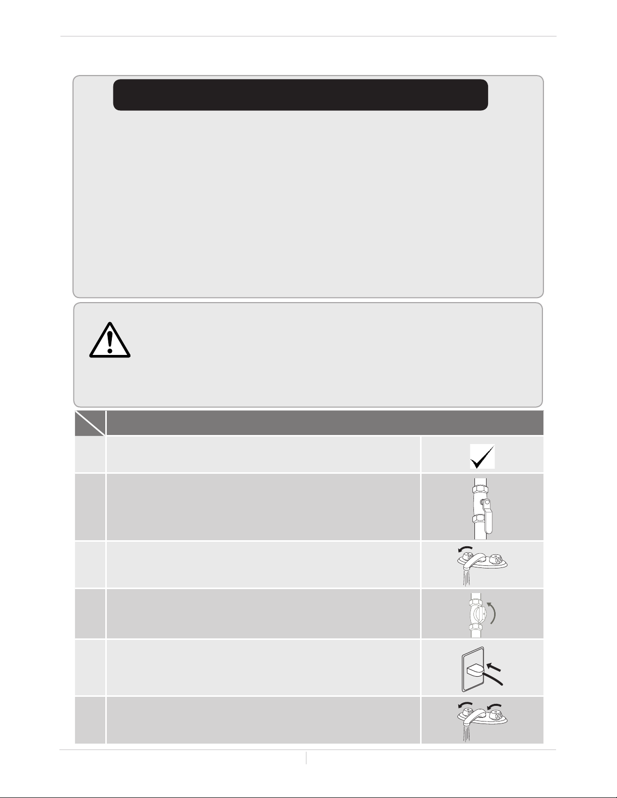
Installaon Manual
Inialial operaon
INITIAL OPERATION
FOR YOUR SAFETY, READ BEFORE OPERATING
Check the GAS and WATER CONNECTIONS for leaks before firing unit for the first time.
Open the main gas supply valve to the unit using only your hand to avoid any spark. Never use
tools. If the knob will not turn by hand, do not try to force it; call a qualified service technician.
Forced repair may result in a fire or explosion due to gas leaks.
Be sure to check for the presence of leaking gas toward the bottom of the unit because some
gases are heavier than air and may settle towards the floor.
Check the GAS PRESSURE. Refer to pp. 28 and 45.
Do not try to light the burner manually. It is equipped with an electronic ignition device which
automatically lights the burner.
Check for PROPER VENTING and COMBUSTIBLE AIR to the water heater.
Purge the GAS and WATER LINES to remove any air pockets.
Do not use this appliance if any part has been under water. Immediately contact a qualified
installer or service agency to replace a flooded water heater. Do not attempt to repair the unit!
It must be replaced!
IF YOU SMELL GAS:
Do not try to start the water heater.
Do not touch any electric switches; do not use any phone in your building.
Immediately call your gas supplier from a neighbor’s phone. Follow the gas
WARNING
supplier’s instructions.
If you cannot reach your gas supplier, call the fire department.
Failure to observe these warnings could lead to fire or an explosion, resulting in
severe injury or death.
Operation
Once the above checks have been completed, please clean filter
1.
of any debris. Refer to p. 45 for instructions.
Fully open the manual water control valve on the water supply
2.
line.
Open a hot water tap to verify that water is flowing to that tap,
3.
then close the hot water tap.
Fully open the manual gas control valve installed.
4.
Turn on the 120 VAC, 60 Hz power supply to the water heater.
5.
Now you are ready to enjoy hours of endless hot water.
6.
37 Page
Page 38
Owner's Guide
Owner's Guide
CONGRATULATIONS
Congratulations and thank you for choosing our tankless water heater.
Before use, we recommend that you read through this owner's guide
carefully. Keep this manual for future reference.
If you need an additional manual, contact the manufacturer or your
local distributor. When you call, please tell us the product name and
the serial number of your unit written on the rating plate of the water
heater.
38 Page
Page 39
OPERATING SAFETY
Owner's Guide
Operang Safety
FOR YOUR SAFETY READ BEFORE OPERATING
WARNING:
causing property damage, personal injury or loss of life.
A. This appliance does not have a pilot. It is equipped with an ignition device which automatically
lights the burner. Do not try to light the burner by hand.
B. BEFORE OPERATING smell all around the appliance area for gas. Be sure to smell next to the
floor because some gas is heavier than air and will settle on the floor.
WHAT TO DO IF YOU SMELL GAS
C. Use only your hand to turn the gas shutoff valve. Never use tools. If the valve will not turn
by hand, don’t try to repair it, call a qualified service technician. Force or attempted repair may
result in a fire or explosion.
D. Do not use this appliance if any part has been under water. Immediately contact a qualified
installer or service agency to replace a flooded water heater. Do not attempt to repair the unit!
It must be replaced!
If you do not follow these instructions exactly, a fire or explosion may result
instructions.
OPERATING INSTRUCTIONS
1. STOP! Read the safety information above on this label.
2. Turn off all electric power to the appliance.
3. Do not attempt to light the burner by hand.
4. Turn the gas shutoff valve located on the outside of the unit to the closed position.
5. Wait five (5) minutes to clear out any gas. If you then smell gas, STOP! Follow “B” in the
safety information above on this label. If you don’t smell gas, go to the next step.
6. Turn the gas shutoff valve located on the outside of the unit to the open position.
7. Turn on all electrical power to the appliance.
8. If the appliance will not operate, follow the instructions in “To Turn Off Gas to Appliance,” and
call your service technician or gas supplier.
TO TURN OFF GAS TO APPLIANCE
1. Turn off all electric power to the appliance if service is to be performed.
2. Turn the gas shutoff valve located on the outside of the unit to the closed position.
39 Page
Page 40
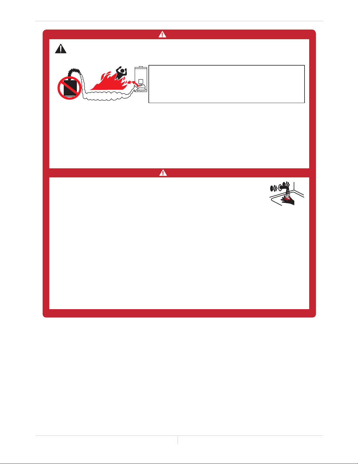
Owner's Guide
Operang Safety
DANGER
Vapors from flammable liquids will explode and catch fire causing death or severe burns.
Do not use or store flammable products such as gasoline, solvents or adhesives in the same room or area near
the water heater.
Do not install water heater where flammable products will be stored or used
unless the main burner is at least 18” above the floor. This will reduce,
Flammable Vapors
FLAMMABLES
Keep flammable products:
1. Far away from heater.
2. In approved containers.
3. Tightly closed and out of reach of children.
4. Water heater has a main burner, which may come
on at any time and will ignite flammable vapors.
1. Water temperature over 125°F (52°C) can cause severe burns instantly or death from scalds.
2. Children, disabled and elderly are at highest risk of being scalded.
3. Feel water before bathing or showering.
4. Temperature limiting valves are available. See manual.
5. The outlet temperature of the water heater is set at 120°F (50°C). If you require water temperatures below this
setting, follow the instruction manual.
6. Use this heater at your own risk. Test the water before bathing or showering. Do not leave children or an infirm
person unsupervised. See your local water supply company [plumbing hardware retailer] for temperature limiting
valves that are available.
Read and follow water heater warnings and instructions. If the owner’s manual is
missing, contact the retailer or manufacturer.
but not eliminate the risk of vapors being ignited by the main burner.
Vapors:
1. Cannot be seen.
2. Are heavier than air.
3. Go a long way on the floor.
4. Can be carried from other rooms to the main
burner by air currents.
DANGER
HOTHOT
CHAUDECHAUDE
CHAUDE
BURN
BRÛLURE
HOT
A pressure relief valve listed as complying with the standard for Relief Valve and Automatic Gas Shutoff Devices for
Hot Water Supply System, ANSI Z21.22 ・ CSA 4.4, shall be installed at the time of installation of the water heater
in the location specified by the manufacturer. Local codes shall govern the installation of relief devices for safety
operation of the water heater. The relief valve must not be removed or plugged.
No valve shall be placed between the relief valve and the water heater. The relief from the discharge of the pressure
relief valve shall be disposed of in a suitable place where it will cause no damage. Also, there shall be no other
reducing coupling or other restrictions installed on the discharge line to restrict flow.
See Installation Manual heading “PRESSURE RELIEF VALVES” for installation and maintenance of relief valve discharge
line and other safety precautions.
40 Page
Page 41
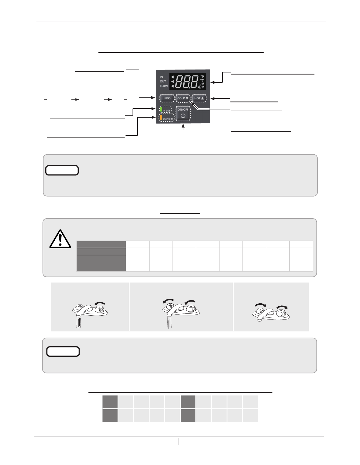
Owner's Guide
Normal Operaon
NORMAL OPERATION
BUILT-IN AND REMOTE CONTOROLLER
"INFO" Button
in the following sequence.
Inlet water
temperature
Outlet water
temperature
Water
IN USE LED (Green)
The indicator lights during combustion.
STAND BY LED (Orange)
The indicator turns on when the
heater is ready for operation.
When the remote controller is installed, it will take priority over the built-in controller.
NOTICE
The controller has an energy saving mode. Five minutes after the water heater stops
operating, the backlight of the controller turns off.
The backlight of the remote will turn back on once the water heater begins firing again.
Display for Temperature
When the STAND BY LED is ON, the
hot water set temperature will be
displayed.
"HOT" Button
"COLD" Button
Press the "HOT" button or the "COLD"
button to set the hot water temperature.
"ON/OFF" Button
Press this button to start
or stop operation.
Temperatures above 125 °F (52 °C) can cause severe burns or death from scalding.
Children, disabled and the elderly are at high risk of being injured.
WARNING
Time to produce
1. Open a cold water
fixture.
NOTICE
GENERAL
°F 120 125 130 135 140 145 150 155
°C 49 52 54 57 60 63 66 68
more
serious burn
Flow rate to activate the water heater: 0.5 gallon per minute at the default set
temperature (1.9 L/min).
Flow rate to keep the water heater running: 0.4 gallon per minute (1.5 L/min).
than 5
min.
2. Mix hot water with the cold water
to get the correct temperature water.
1½ to 2
min.
about
30 sec.
about
10 sec.
less than
5 sec.
less than
3 sec.
3. When finished, close the
water fixtures.
about
1½ sec.
about
1 sec.
TEMPERATURE TABLE OF THE CONTROLLER
°F 100 105 110 115 120* 125 130 135 140
°C 38 40 43 45 50* 52 55 57 60
*Factory setting (Default)
41 Page
Page 42
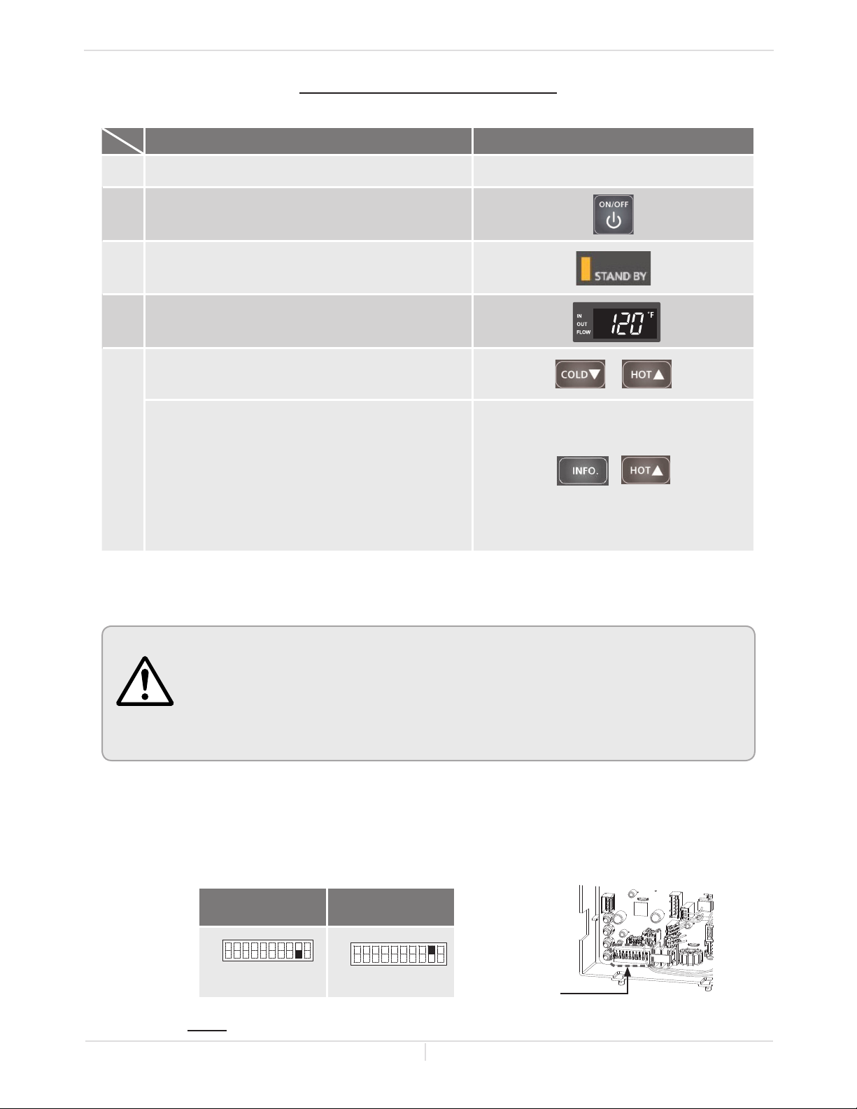
TEMPERATURE SETTINGS
OFF
1 2 3 4 5 6
7 8 9
10
OFF
1 2 3 4 5 6 7 8 9 10
-Using controller-
Operation Screen on the controller
Turn on the 120 VAC power supply to the water heater.
1.
Press the "ON/OFF" button on the controller in order to
2.
turn the controller on.
When ON, the STAND BY LED is lit.
3.
It shows the set temperature on its display as shown in
4.
the picture on the right. (EX.: 120 °F)
Press the "HOT" button or the "COLD" button to set the
temperature setting of the unit.
Increasing temperature
from 120 °F (50 °C) to 125 °F (52 °C) :
1. The water heater must be Stand By to increase the
5.
temperature.
2. Press the "HOT" button to set 120 °F (50 °C).
3. Press and hold the "INFO" button and the "HOT"
button for at least 3 seconds. The remote will emit a
beep and change to 125 °F (52 °C).
4. Press the "HOT" button to set up to 140 °F (60 °C).
Owner's Guide
Normal Operaon
(EX.: 120 °F)
-Temperature seng on the PCB-
(Without controller)
• Adjust the appropriate DIP switches according to temperature as shown
below. DO NOT adjust the other DIP switches.
• Turn off the power supply to the water heater before changing the DIP switch
settings.
WARNING
There are 2 preset temperatures,120 °F (50 °C) and 140 °F (60 °C), that you can select from by changing
the DIP switch settings on the computer board without the controller. See below.
When the controller is in normal operation, the set temperature of the controller is given
priority over the set temperature of the DIP switch settings.
• Failure to observe these warnings could lead to carbon monoxide poisoning,
severe personal injury, or death.
• The temperature has been preset at the factory to 120 °F (50 °C).
120 °F (50 °C)
DEFAULT
ON
No. 9 : OFF
140 °F (60 °C)
ON
No. 9 : ON
Bank of
DIPswitches
Computer board
NOTE: The dark square indicates the correct DIP switch position.
42 Page
Page 43
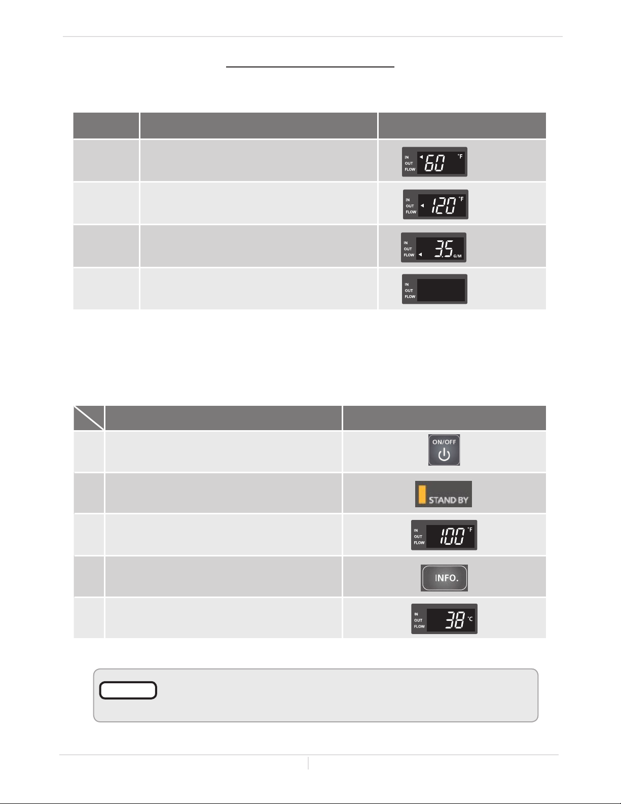
Owner's Guide
Normal Operaon
ADDTIONAL FEATURES
-Informaon mode-
You can get some information about the water heater condition by pressing the "INFO" button. For more
information, follow the procedures below:
INFO
BUTTON
Operation Screen on the controller
Inlet water
temperature
(EX.: 60 °F)
Outlet water
temperature
(EX.: 120 °F)
Water flow
(EX.: 3.5 GPM)
1st. press
2nd. press
3rd. press
4th. press
Inlet water temperature will be displayed on the
controller by pressing the "INFO" button.
Outlet water temperature will be displayed on the
controller by pressing the "INFO" button.
Water flow rate, in gpm, will be displayed on the
controller by pressing the "INFO" button.
Press the "INFO" button to exit information mode.
-Unit conversion mode-
Units of measure can be changed from Imperial to Metric and vice versa. For example, temperature can
be changed from °F to °C. Flow rate will also change from gallons per minute to liters per minute when
this setting is changed. Follow this procedure to change this setting:
Operation Screen on the controller
Press the "ON/OFF" button on the controller in
1.
order to turn the controller on.
When ON, the orange LED is lit.
2.
The previous set temperature will be displayed on
3.
the screen.
Press the "INFO" buttons for at least 3 seconds.
4.
The set temperature should now be displayed in the
5.
alternate unit of measurement.
NOTICE
When the water heater is connected with the remote controller, the builtin controller will not operate temperature settings. It will only work for the
information mode (Indoor model only).
(EX.: 100 °F)
(EX.: 38 °C)
43 Page
Page 44
Owner's Guide
Normal Operaon
FLOW
The flow rate through the water heater is limited to
a maximum of 7.0 GPM (26.5 L/min).
The temperature setting, along with the supply
temperature of the water, will determine the flow
rate output of the water heater.
Please refer to the temperature vs. gallons per
minute charts on p. 56 to determine the likely flow
rates based on your local ground water temperature
and your desired outlet water temperature.
Refer to the table on the right for typical
household plumbing fixture flow rates to determine what the water heater can do in a household
application.
Appliance/Use
Lavatory Faucet 1.0 3.8
Bath Tub 4.0 – 10.0 15.2 - 37.8
Shower 2.0 7.5
Kitchen Sink 1.5 5.6
Dishwasher 1.5 5.6
Washing machine 4.0 15.2
Taken from UPC 2006
Household Flow Rates
Flow rate
GPM (US) L/min
FREEZE PROTECTION SYSTEM
This water heater comes equipped with heating blocks to protect the unint from damage associated
with freezing. When the freeze protection thermostat senses air temperature below 36.5 °F (2.5 °C),
the blocks will heat up to prevent freezing of the unit.
To operate these freeze protection systems, there has to be electrical power to the unit. Damage
to the heat exchanger caused by freezing temperatures due to power loss is not covered under the
warranty. In cases where power losses can occur, consider the use of a backup power supply.
In any areas subject to freezing temperatures, the manufacturer highly recommends an indoor installa-
tion with an indoor model.
The manufacturer also highly recommends the use of a backflow preventer (sold separately) to mini-
mize the amount of cold air entering through the exhaust venting when the water heater is off.
It is the installer’s responsibility to be aware of freezing issues and take all preventative measures. The
manufacturer will not be responsible for any damage to the heat exchanger as a result of freezing.
If you will not be using your heater for a long period of time:
1. Completely drain the water out of the unit. Refer to p. 45.
2. Disconnect power to your heater.
This will keep your unit from freezing and being damaged.
NOTICE
Only pipes within the water heater are protected by the freeze protection system.
Any water pipes (hot or cold) located outside the unit will not be protected.
Properly protect and insulate these pipes from freezing.
MAINTENANCE AND SERVICE
• Turn off the electrical power supply and close the manual gas shutoff valve
and the manual water control valve before servicing.
WARNING
Clean the cold-water inlet filter. (Refer to the Unit Draining and Filter Cleaning Section on p. 45.)
Be sure that all openings for combustion and ventilation air are not blocked.
The venting system should be checked annually for any leaks, corrosion, blockages or damage.
The burner should be checked annually for dust, lint, grease or dirt.
Keep the area around the water heater clear. Remove any combustible materials, gasoline or any
flammable vapors and liquids.
If the relief valve discharges periodically, it may be due to thermal expansion in a closed water supply
system. Contact the water supplier or local plumbing inspector on how to correct this situation.
Visually check the burner flames through the burner window in the burner assembly located at the
middle of the water heater. (See the following page.)
• Failure to do so could result in severe personal injury, or death.
44 Page
Page 45
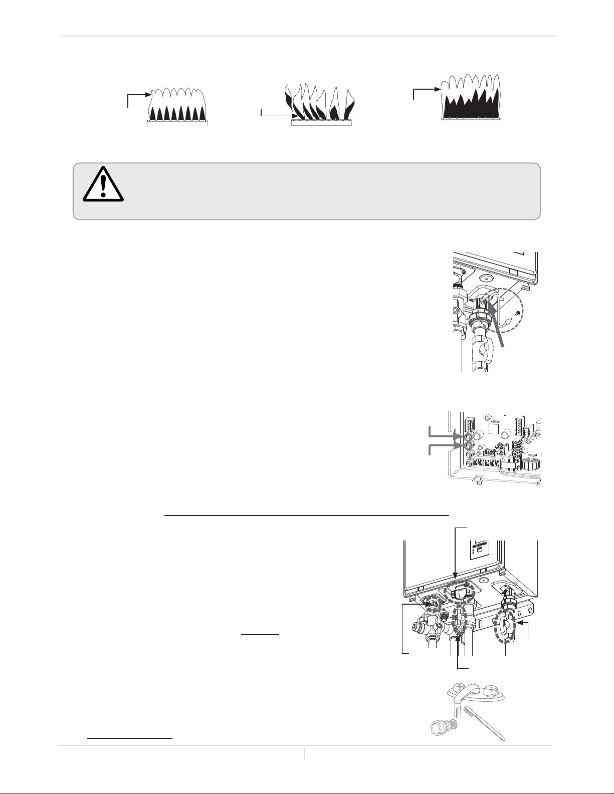
Owner's Guide
Normal Operaon
The manufacturer recommends having the water heater checked once a year or as necessary by a licensed
technician. If repairs are needed, any repairs should be done by a licensed technician.
Flame
blowing up
Red or Yellow
-Measuring inlet gas pressure-
1. Turn off all electric power to the water heater if service is to be performed.
2. Turn the manual gas valve located on the outside of the unit to the off position.
3. Failure to follow these steps could lead to fire or explosion, resulting in personal injury
WARNING
The water heater cannot perform properly without sufficient inlet gas pressure. Below are instructions
on how to check the inlet gas pressure. THIS IS ONLY TO BE DONE BY A LICENSED PROFESSIONAL.
1. Shut off the manual gas valve on the gas supply line.
2. Remove the screw from the pressure port which is located on the gas inlet of
the water heater shown in the diagram on the right.
3. Connect the manometer to the pressure port and zero the manometer.
4. Re-open the manual gas valve. Verify that there are no gas leaks.
5. With all gas burning equipment off, take a reading of the static gas pressure and
make a note of it.
6. Measure gas supply pressure at maximum heater operation: Open hot water
faucets to create maximum flow. Press the MAX button on the computer board.
(Refer to the diagram below.) Take a reading of the supply dynamic gas pressure
with all gas burning equipment running at maximum rate.
7. The static and dynamic pressures should be within the ranges specified on the
heater's rating plate and the table on p. 28
8. The difference of static to dynamic pressure should not exceed 1.5"
W.C. Pressure drops that exceed 1.5" W.C. can indicate restricted gas
flow, undersized gas lines, and/or undersized supply regulators.
9. Measure gas supply pressure at minimum heater operation: Reduce
water flow so the heater is running at minimal operation. Press the
MIN button on the computer board. (Refer to the right diagram.) Take
a supply gas pressure reading and verify that it is within the specified
inlet gas pressure range.
or death.
MAX
button
MIN
button
Pressure
port
Computer board
UNIT DRAINING AND FILTER CLEANING
1. Close the manual gas shutoff valve.
2. Turn off power to the unit and wait a couple of seconds. Turn on
again.
3. Wait 30 seconds, and then turn off power to the unit.
4. Close the inlet water valve.
5. Open all hot water taps in the house. When the residual water flow
has ceased, close all hot water taps.
6. Have a bucket or pan to catch the water from the unit’s drain plugs.
If Isolation valves are installed, open the drains to drain the water. If
isolation valves are not installed, unscrew the two drain plugs (large
and small) to drain all the water out of the unit. Do not lose the
o-rings that will be on the two drain plugs.
7. Wait a few minutes to ensure all water has completely drained from
the unit.
8. Clean the filter: Check the water filter located within the cold inlet.
With a tiny brush, clean the water filter of any debris which may have
accumulated and reinsert the filter back into the cold water inlet.
9. Securely screw the drain plugs back into place.
Hand- tighten only.
45 Page
Drain plug
(Small)
Drain plug
with Filter (Large)
Gas
valve
Water valve
Page 46
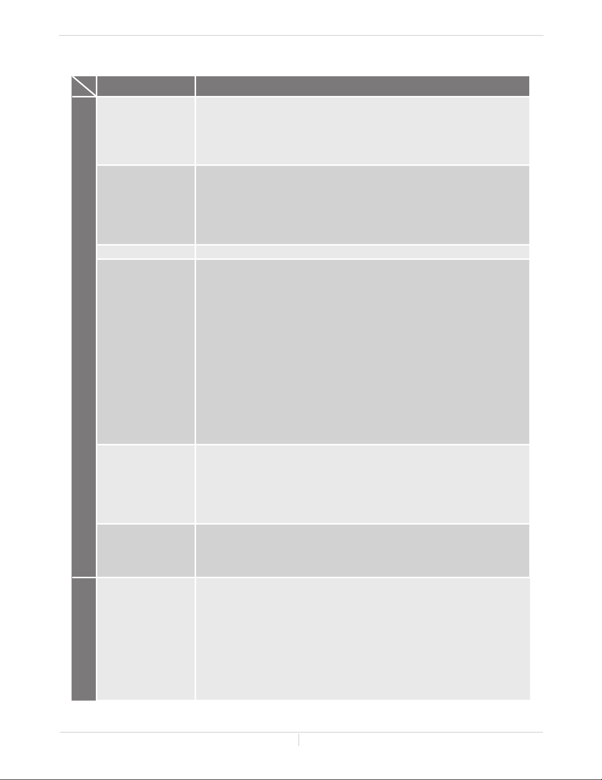
TROUBLESHOOTING
PROBLEM SOLUTIONS
It takes a long time to
get hot water at the
fixtures.
The water is not hot
enough.
The water is too hot. Is the set temperature set too high? (p. 42)
The hot water is not
available when a
fixture is opened.
The hot water turns
TEMPERATURE and AMOUNT OF HOT WATER
cold and stays cold.
Fluctuation in hot
water temperature.
Unit does not ignite
when water goes
through the unit.
WATER HEATER
The time it takes to deliver hot water from the water heater to your
fixtures depends on the length of piping between the two. The longer the
distance or the bigger the pipes, the longer it will take to get hot water.
If you would like to receive hot water to your fixtures more quickly, you
may want to consider a hot water recirculation system. (p. 35)
Compare the flow and temperature. See the charts on p. 56.
Check cross plumbing between the cold water lines and hot water lines.
Is the gas supply valve open fully? (p. 37)
Is the gas line sized properly? (p. 28)
Is the gas supply pressure sufficient? (pp. 28 and 45)
Is the set temperature set too low? (p. 42)
Make sure the unit has a 120 VAC, 60 Hz power supply.
If you are using the remote controller and/or built-in controller, is the
power button turned on?
The time it takes to deliver hot water from the water heater to your
fixtures depends on the length of piping between the two. The longer the
distance or the bigger the pipes, the longer it will take to get hot water.
Is the gas supply valve open fully? (p. 37)
Is the water supply valve open fully? (p. 37)
Is the filter on the cold water inlet clean? (p. 45)
Is the hot water fixture open sufficiently to draw at least 0.5 GPM
(1.9 L/min) through the water heater? (p. 41)
Is the unit frozen? (p. 44)
Is there enough gas in the tank / cylinder? (For Propane model)
Is it plumbed backwards with reverse plumbing?
Is the flow rate enough to keep the water heater running? (p. 41)
If there is a recirculation system installed, does the recirculation line have
enough check valves? (p. 35)
Is the gas supply valve open fully? (p. 37)
Is the filter on the cold water inlet clean? (p. 45)
Are the fixtures clean of debris and obstructions?
Is the filter on the cold water inlet clean? (p. 45)
Is the gas line sized properly? (p. 28)
Is the supply gas pressure sufficient? (pp. 28 and 45)
Check for cross connection between cold water lines and hot water lines.
Is the power on the water heater?
Is the gas on?
Is the flow rate over 0.5 GPM (1.9 L/min)? (p. 41)
Is the filter on the cold water inlet clean? (p. 45)
Check for reverse connection and cross connection. (p. 30)
If you use the remote controller and/or built-in controller, is the power
button turned on? (p. 41)
Check if the inlet temperature is too high. If it is too close to the set
temperature, the water heater will not activate.
Owner's Guide
Troubleshoong
46 Page
Page 47
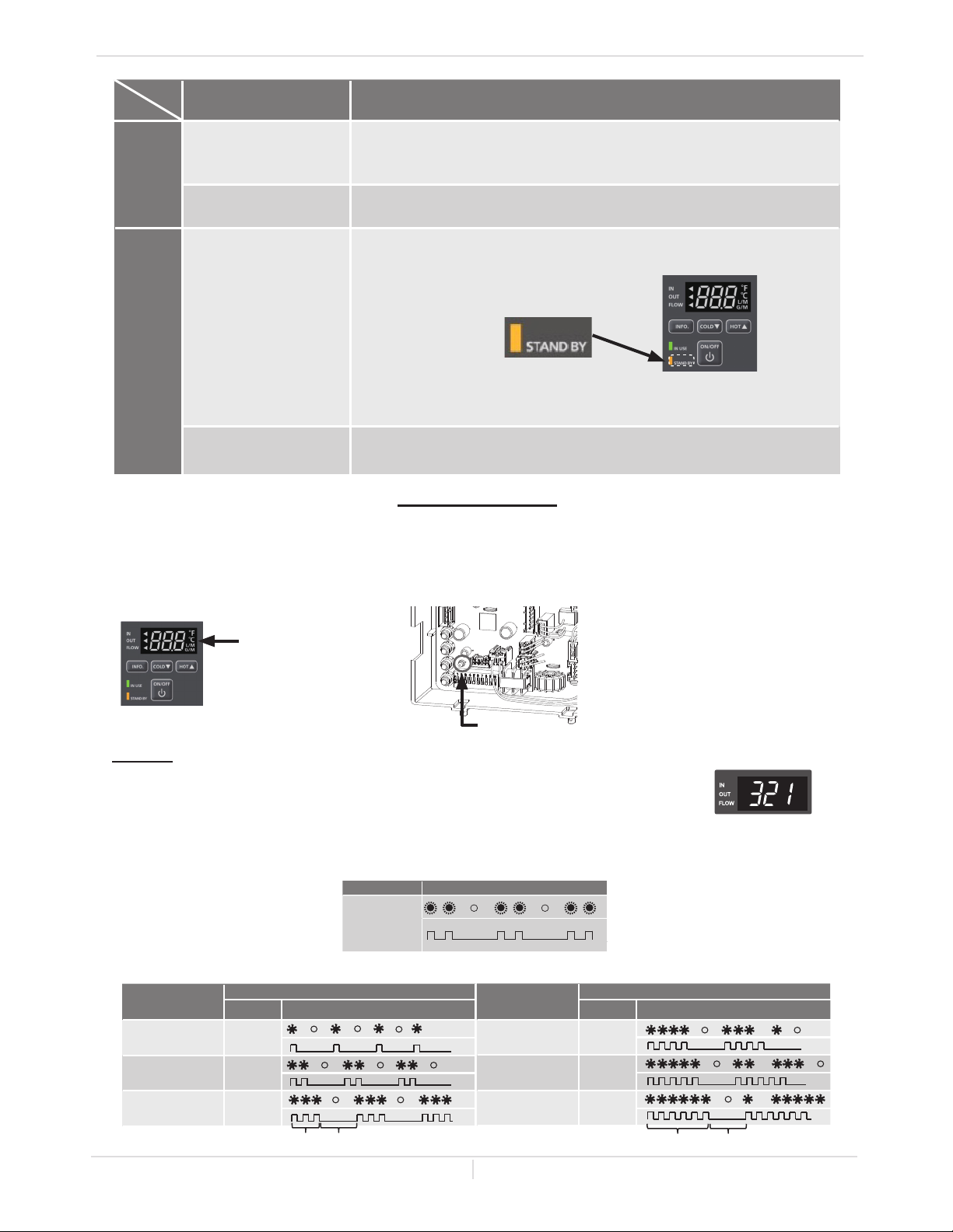
PROBLEM SOLUTIONS
Owner's Guide
Troubleshoong
The fan motor is
still spinning after
operation has stopped.
Unit sounds abnormal
WATER
HEATER
while in operation
Controller does not
display anything when
the power button is
turned on.
This is normal. After operation has stopped, the fan motor keeps
running from 15 to 70 seconds in order to re-ignite quickly, as well
as purge all the exhaust gas out of the flue.
Contact the manufacturer at 1-877-737-2840.
Make sure the water heater is supplied with power.
Make sure the connection to the water heater is correct. (p. 34)
When the controller is turned ON,
STAND BY LED is lit.
NOTICE:
When the water heater has not operated for five minutes or more,
CONTROLLER
BUILT-IN/REMOTE
An ERROR code is
the display of the controllers turns off to conserve energy.
Please see pp. 48 and 49.
displayed.
ERROR CODES
The water heater has self-diagnostics for safety and convenience when troubleshooting.
If there is a problem with the water heater itself, or the installation of the unit, the error code will be
displayed on the temperature controller and remote controller.
Consult with the table on the following pages for a description of each error code.
Error code indicator
on the built-in/remote
controller
Error code on the computer board
Indicated by 1/2-second flashes on
the Green LED.
Green LED
Example: If your unit has a “321” error code (which signifies an inlet thermistor failure)
Indicator on the built-in controller or remote controller : “321” will be displayed
on the screen.
Error code
Green LED on the computer board: The green LED on the computer board will indicate this code with
two flashes every 1/2 second. The pattern will repeat with a three second delay between patterns.
Error code Green LED
321
on on on on
off off off off off
on on
Error Indication
Error Code
on the temperature
controller
031 701 711
311 321 341
391
111 121
The number
of flashes
One
Two
Three
on on
off
0.5 sec. on,
0.5 sec. off
Green LED
Flash paern
off
3 sec. off
Error Code
on the temperature
controller
611
101 941 991
510 551 721
The number
of flashes
Four
Five
Six
Green LED
Flash paern
0.5 sec. on, 0.5 sec. off 3 sec. off
47 Page
Page 48
Owner's Guide
Troubleshoong
-Fault Analysis of Error Codes-
If the error code is displayed on the computer board of the water heater or remote controller and/or
temperature controller, please check the following. After checking, consult with the manufacturer.
Remote
031
101
111*
121*
311*
321*
341*
Green
LED
One Time Incorrect DIP switch
Five Times Warning for the
Three Times Ignition failure Check if the Hi-limit switch (Part #411) is properly
Three Times Loss of flame Check if the Hi-limit switch (Part #411) is properly
Two Times Outlet thermistor
Two Times Inlet thermistor
Two Times Exhaust thermistor
Malfunction
description
setting
“991” error code
failure
failure
failure (Indoor
model only)
Diagnosis
Check the DIP switch settings on the PCB (Part #701).
Check if the gas type of the water heater matches
the gas supplied to it.
Check if there is any blockage in the intake air and/
or exhaust.
If the water heater is installed as a direct-vent
system, check whether there is enough distance
between the intake air terminal and the exhaust
terminal.
Check the altitude/elevation of area of where the
water heater is installed and match the appropriate
DIPswitches.
Check if there is grease and/or dirt in the burner (Part
#101) and the fan motor (Part #103), especially if the
water heater has been installed in a contaminated area.
Check if the DIP switches match gas type of the water
heater.
Check the manifold pressure at Max. and Min.
Check combustion chamber tube (Part #117) to make
sure it is clear and securely installed.
functioning.
Check for connection/breakage of wires (Part #412, 707,
708, 709 710), burn marks on the computer board (Part
#701), and/or soot on the flame rod (Part #108).
Check if there is a buzzing spark ignition sound
coming from the burner (Part #101) when water
heater prepares for combustion.
Listen for the double “clunk” sound coming from gas
valve assembly (Part #102) when the water heater
goes into combustion.
Check if there is leaking from heat exchanger (Part #401).
Check that the gas is turned on.
Check gas supply.
functioning.
Check for connection/breakage of wires (Part #412,
707, 708, 710), burn marks on the computer board (Part
#701), and/or soot on the flame rod (Part #108).
Check if there is leaking from heat exchanger (Part #401).
Check gas supply.
Check for connection/breakage of wires and/or
debris on thermistor (Part #407, 408, 715).
Check the resistance.
*These error codes will be cleared when water flow stops.
48 Page
Page 49
Owner's Guide
Troubleshoong
Remote
391*
510
551
611*
701*
711*
721*
741
751
941
991
Green
LED
Two Times Air-fuel ratio rod
Six Times Abnormal main gas
Six Times Abnormal gas
Four Times Fan motor fault Check for connection/breakage of wires, dust buildup
One Time Computer board fault Check for connection/breakage of wires (Part #711).
One Time Gas solenoid valve
Six Times False flame
N/A Miscommunication
N/A Miscommunication
Five Times Abnormal exhaust
Five Times Imperfect
Malfunction
description
failure
solenoid valve
solenoid valve
drive circuit failure
detection
between the water
heater and remote
controller
between the water
heater and built-in
controller (Indoor
model only)
temperature (Indoor
model only)
combustion
Check for connection/breakage of wires (Part #708)
and/or soot on the AFR rod (Part #108).
Check for connection/breakage of wires (Part #707)
and/or burn marks on the computer board (Part #701).
Check for signs of vent corrosion.
Check gas valve contacts and gas valve wire harness
connections for signs of rust or corrosion.
Check for connection/breakage of wires (Part #707)
and/or burn marks on the computer board (Part #701).
Check gas valve contacts and gas valve wire harness
connections for signs of rust or corrosion..
in the fan motor (Part #103) and/or burn marks on
the computer board (Part #701).
Check for frozen/corrosion of connectors (Part #103).
Refer to the 111 and 121 error codes.
Check if there is leaking from heat exchanger (Part #401).
Check the model type of the remote controller.
Inspect the connections between the water heater
and remote controller.
Check the power supply of the water heater.
Inspect the connections between the water heater
and temperature controller.
Check the power supply of the water heater.
Check to see of the exhaust temperature is higher
than 149°F (65°C).
Check if the gas type of the water heater matches
the gas supplied to it.
Inspect the environment around the water heater.
Determine how long the water heater has been
installed and match DIPswitches.
Check the altitude/elevation of the area of where
the water heater is installed.
Check if there is any blockage in the intake air and/
or exhaust.
If the water heater is installed as a direct-vent system,
check whether there is enough distance between the
intake air terminal and the exhaust terminal.
Check if there is grease and/or dirt in the burner (Part
#101) and the fan motor (Part #103), especially if the
water heater has been installed in a contaminated area
Check the DIP switches match gas type of the water
heater.
Check the manifold pressure at Max. and Min.
Check combustion chamber tube (part #117) to see
if it is clear and securely installed.
*These error code will be clear when water flow stops.
Diagnosis
49 Page
Page 50
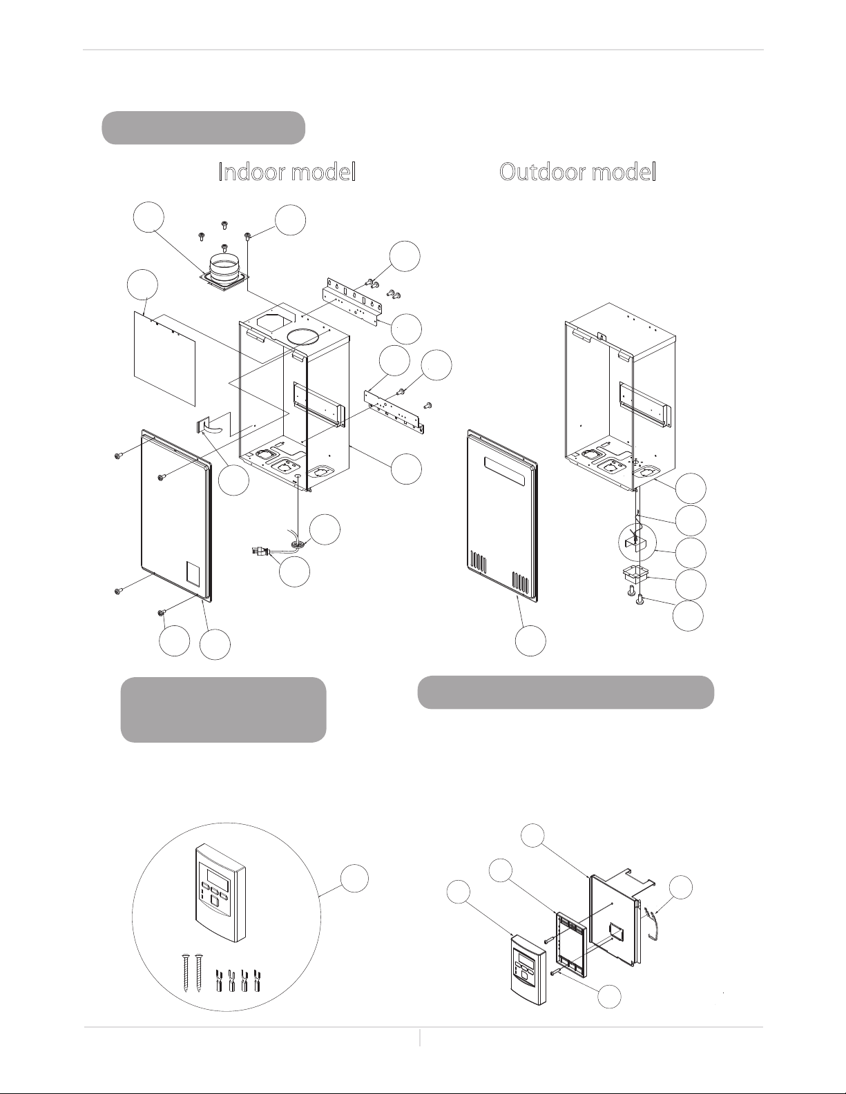
COMPONENTS DIAGRAM
722
721
056
721
724
Case assembly
Indoor model Outdoor model
Owner's Guide
Components Diagram
003
007
714
052
704
702
052
004
004
001
052
001
704
006
005
052
050
002
Temperature
remote controller
002
Built-in controller
Indoor model
723
50 Page
Page 51
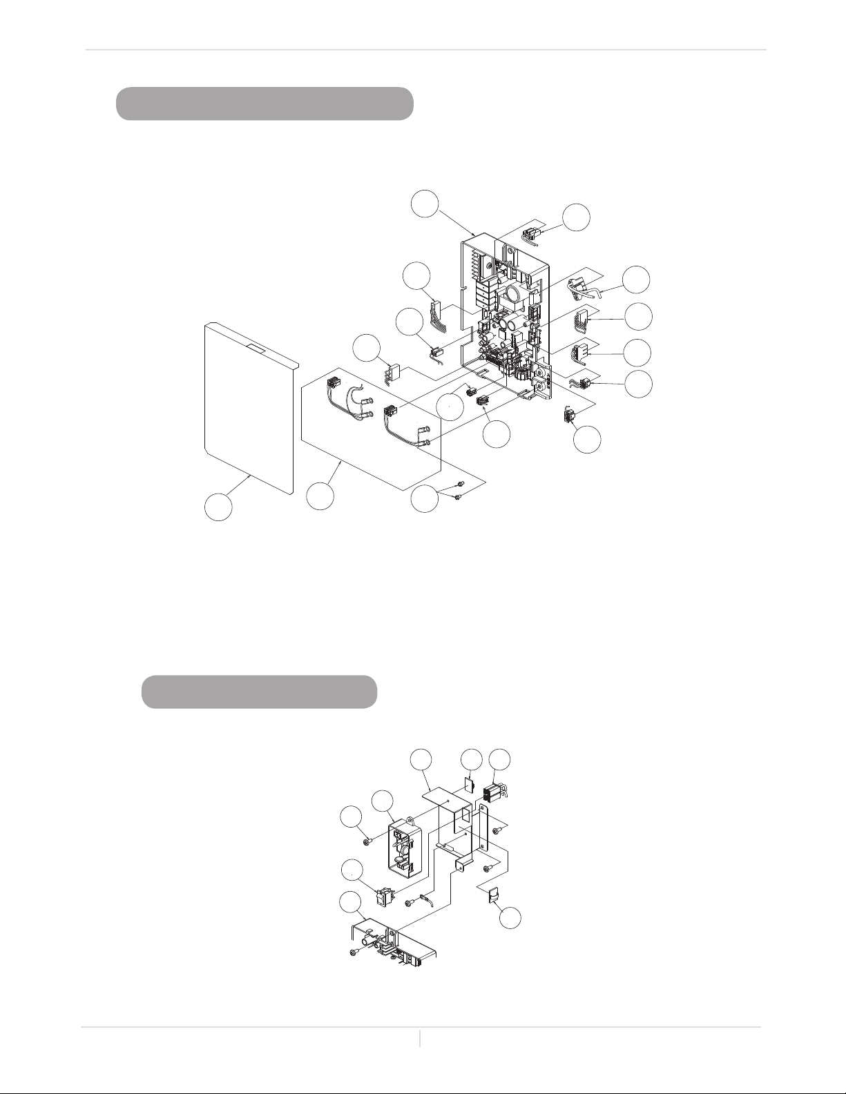
Computer board assembly
Owner's Guide
Components Diagram
701
709
713
716
for
Indoor model
for
Outdoor model
706
707
711
060
408
407
710
103
708
402
402
Surge box assembly
053
705
701
703
51 Page
120
712
710
712
Page 52
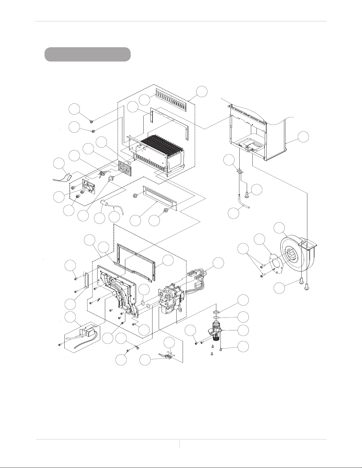
Burner assembly
053
053
106
107
108
708
Owner's Guide
Components Diagram
Burner assembly
101
104
115
401
116
110
061
Manifold
assembly
053
120
709
109
102
111
114
055 062
709
053 711
112 053
150
057
113
117
055
053
117
103
105
064
707
054
119
151
118
051
52 Page
Page 53
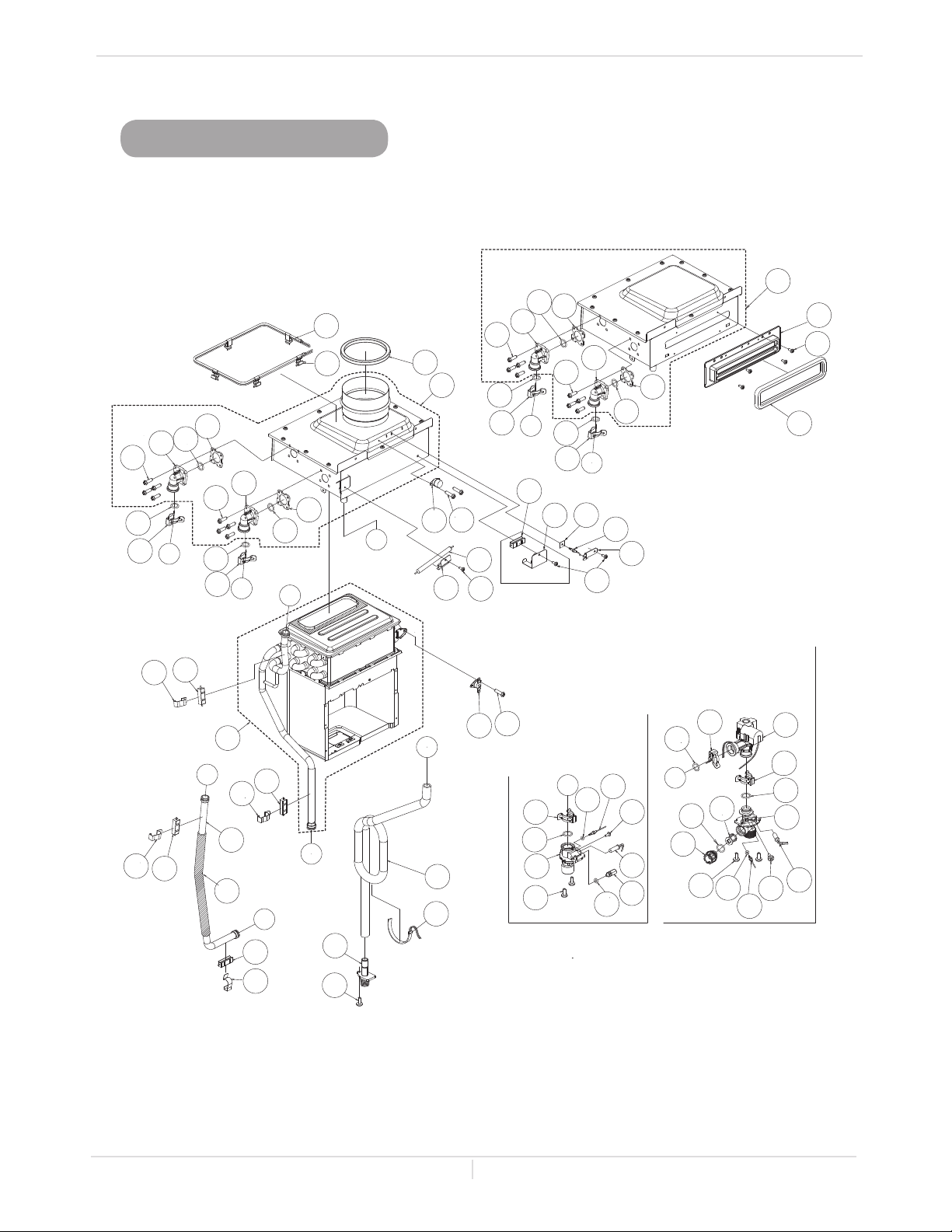
Water Way assembly
Owner's Guide
Components Diagram
063
455
458
463
451
A
455
413
467
063
455
458
Indoor Model
463
467
455
B
A
412
452
Outdoor Model
417
455
467
463
063
154
417
466 064
455
458
A
418
E
413
450
053
for Indoor model
463
063
455
458
419 465
467
455
B
715
464
053
153
053
152
451
413
455
D
405
456
458
052
406
453
407
059
402
459
457
404
416
058
401
B
414
451
462
C
468
D
414
451
403
052
E
415
461
411
460
457
409
052
C
408
453
059
416
410
454
53 Page
Page 54
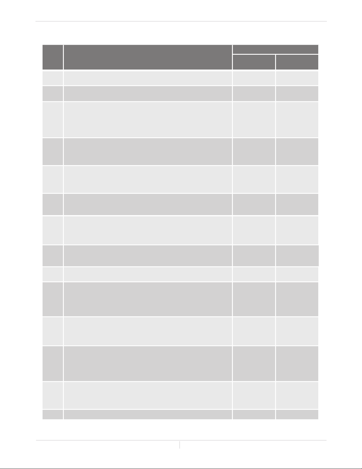
PARTS LIST
Item # Description
Owner's Guide
Parts List
Part #
140 model T-H3M model
001 Case assembly for Indoor model
Case assembly for Outdoor model
002 Front cover for Indoor
Front cover for Outdoor
003
004
005
006
007
050
051
052
053
054
055
056
057
058
059
060
061
062
063
064
101
102
103 Fan motor for Indoor model
104
105
106
107
108
109
110
111
112
113
114
115
116
117
118
119
120 Surge box plate N/A EK466
Intake air port assembly
Bracket
Junction box
Power supply cord assembly
Back guard panel
Truss screw M4×12 (W/Washer) SUS410
Truss screw M4×10 (W/Washer) SUS410
Truss screw M4×10 (Coated) SUS3
Truss screw M4x10 SUS
Hex head screw M4×12 (W/Washer) SUS3
Hex head screw M4x8 FEZN
Pan screw M4x20 SUS410
Tap tight screw M4x12 FEZN
Tapping screw M3x6 SUS3 Pan head
Tapping screw M4x6 SUS3 Truss head
Plus bind Screw M3x6 FEZN
Pan screw M4x8 MFZN
Wire clamp 60
Truss tapping screw M4x10 (S coated)
Screw M3x6 SUS3 Binding head
Burner assembly
Manifold with gas valve assembly LP
Manifold with gas valve assembly NA
Fan motor for Outdoor model
Burner gasket
Fan damper for Indoor model
Fan damper for Outdoor model
Burner window
Rod holder gasket
Flame rod
Igniter rod
Rod holder
Rod cap
Burner damper Indoor
Burner damper Outdoor
Manifold gasket A
Manifold gasket B
Burner holder gasket
Pressure port
Combustion chamber tube
Gas inlet
Gas inlet ring
N/A
N/A
N/A
N/A
100076311
N/A
100074668
100076313
N/A
100074210
100074509
100074211
100074245
100074510
100074248
N/A
100074385
100074272
100074512
N/A
100074526
100074233
N/A
100074514
100076314
100076315
100076317
100074606
100074228
100074216
100076511
100074466
100074218
100074219
100074673
100076318
100074221
100076319
100076320
100076321
100074229
100074230
100074217
100074227
100074528
100076323
100074234
EK450
EK451
EK452
EK453
EK454
EK455
EK190
EK456
EK457
EW000
EW001
EW002
EW003
EW004
EW005
EW018
EKK31
EW00A
EW009
EK191
EW00D
EM167
EW00P
EW00B
EK458
EK459
EK460
EK109
EKK25
EKK2X
EK491
EM381
EKK2V
EKK2W
EK193
EK461
EKK32
EK462
EK463
EK464
EKK2Y
EKK2K
EKK0G
EKK2D
EX019
EK465
EKK2Z
54 Page
Page 55
Item # Description
Owner's Guide
Parts List
Part #
140 model T-H3M model
150
151
152
153
154
401 Primary heat exchanger assembly for 140 Indoor and Outdoor 100076510 EK467
402
403
404
405
406
407 Inlet thermistor 100074398 EKK4J
408 Outlet thermistor 100074680 EK207
409
410
411 Hi-Limit switch 100074412 EM212
412
413
414 Inlet heater 100076326 EK469
415
416
417 Secondary heat exchanger for Indoor model
418
419
O-ring P18 NBR (Black)
O-ring P20 NBR (Black)
Silicon ring for Outdoor model
Exhaust port for Outdoor model
Silicon ring
Flow adjustment valve / Flow sensor
Condensate drain port
Water inlet
Inlet drain plug
Inlet water filter
Water outlet
Outlet drain plug
Overheat-cut-off fuse
Pipe heater
Drain tube
Inlet heater
Secondary heat exchanger for Outdoor model
Secondary heat exchanger heater
Heater fixing plate
100074533
100074242
100074553
100074306
100074250
100074624
100074203
100074377
100074381
100074382
100074627
100074383
100074252
100076325
100076327
100074629
100076507
100076508
100076328
N/A
EZP18
EK042
EK442
EX13J
EKN50
EK129
EKH23
EKK1U
EKK2B
EKK2C
EK104
EKK2E
EX02A
EK468
EK470
EK105
EK471
EK472
EK473
EK474
450
451
452
453
454
455
456
457
458
459
460
461
462 Cold pipe for 140 model 100076509 EK477
463
464
465
466
467
468
Pipe heater fixing plate
Heater fixing plate 16
Fuse fixing plate
O-ring P4 FKM
O-ring P6 FKM
O-ring P14 FKM
O-ring P15 FKM
O-ring P16 FKM
Fastener “14-22”
Fastener “16A”
Fastener “16-25A”
Flat heater
Header connection
Thermistor fixing plate
Exhaust thermistor gasket
Hi-limit switch for exhaust
Gasket
Inlet pipe packing
N/A
100074310
N/A
100076303
100076305
100076306
100076307
100076308
100074290
100074410
100074389
100074686
100076329
100074291
100074296
100074289
100074693
N/A
EK475
EK031
EK476
EZF04
EZF06
EZF14
EZF15
EZF16
EKK24
EM192
EKK39
EK217
EK478
EX13H
EX13L
EKH6G
EK229
EK479
55 Page
Page 56
Owner's Guide
Parts List
Part #
Item # Description
701 Computer board 100076330 EK480
140 model T-H3M model
702
703
704
705
706
707
708
709
710 Freeze protection thermostat 100074369 EKJ59
711
712
713
714
715
716
721
722
723
724
Rubber grommet
Surge box
120 VAC wire for Indoor model
120 VAC wire for Outdoor model
120 VAC Power ON-OFF switch
Remote controller wire for Indoor model
Remote controller wire for Outdoor model
Gas valve wire
Flame rod wire
Igniter assembly
Proportional gas valve wire
Nylon clamp FC6
Computer board cover
Cable clamp for Indoor model
Exhaust thermistor for Indoor model
Exhaust Hi-limit switch wire
Temperature controller for Indoor model
Fixing plate
Temperature remote controller
Remote controller connection wire
N/A
100076100
100074601
100074697
100074326
100076337
100074634
100076340
100076341
100076342
100074642
N/A
100074375
N/A
100074316
100074659
100076567
N/A
100209924
100076471
EK148
EK280
EK146
EK143
EKK4V
EK481
EK138
EK482
EK483
EK484
EK112
EX004
EKK1M
EX13C
EKH6E
EK180
EK487
EK490
TM-RE42
EK489
OUTPUT TEMPERATURE CHART
Chart is based on properly sized gas line
140 model
Output Temperature vs. GPM (Max. 7.0 GPM) with Various Inlet Water Temperature
8.0
40℉ 50℉ 60℉ 70℉
6.0
4.0
2.0
Output hot water GPM
0.0
Set Temp
Incoming temp.
100 105 110 115 120 125 130 135 140
(℉)
40℉
3.7 3.4 3.2 3.0 2.8 2.6 2.5 2.3 2.2
50℉
4.5 4.1 3.7 3.4 3.2 3.0 2.8 2.6 2.5
60℉
5.6 5.0 4.5 4.1 3.7 3.4 3.2 3.0 2.8
70℉
7.0 6.4 5.6 5.0 4.5 4.1 3.7 3.4 3.2
56 Page
88A161-5
2000534687 (REV.B)
 Loading...