


1. Safety
2. Introduction
3. Composition
4. Specification
5. Description of parts & basic operation
6. Warning Message
7. Operation of Transmitter (TX)
8. Operation of Receiver (RX)
9.
Precautions and applications
(At the locating site)
Table of Contents
1
3-1. Main equipment & standard accessories
3-2. Optional equipment
5-1. Transmitter
5-2. Receiver
7-1. Direct connection mode
7-2. External coil mode
7-3. Indirect (Inductive) mode
8-1. Null mode
8-2. Peak mode
8-3. Depth measurement
8-4. Logging data
8-5. Current index (Current measurement)
8-6. Passive mode
8-7. Building wiring
8-8. Probe for non-metallic pipe
3
4
4
4
5
7
7
9
12
13
14
17
19
21
21
22
23
24
25
27
29
30
32
1. SAFETY
Always locate with proper respect and caution. Equipment misuse or
carelessness can result in serious injury or damage to property. Always follow
safety rules.
HAZARD ALERT INFORMATION
BE AWARE OF SAFETY INFORMATION
This is a safety-alert sign. This is placed in the manual and on
your equipment to alert you to the potential for bodily injury or
death.
SIGNAL WORDS
The safety-alert icon is used with the following signal word :
DANGER, WARNING, AND CAUTION. When you see these
words in the manual or on decals on your equipment, carefully read
and follow all instructions. Watch for these words and learn their
meanings.
DANGER – Imminent hazards which, if not avoided, will result in
death or serious injury.
WARNING – Potentially hazardous situation which, if not avoided,
could result in death or serious injury.
CAUTION – Potentially hazardous situation which, if not avoided,
may result in minor personal injury or property damage.
DANGER
WARNING
CAUTION
OPERATOR PREPARATIONS
Important : Read and understand this manual before using the Verifier Locator.
Successful use of the Verifier Locator depends on good locating skills and correct
understanding of receiver response.
GENERAL SAFETY
DANGER : Do not attempt to connect to Live Power without proper protective Equipment
and Training.
DAGER ELECTRIC SHOCK : Death or serious injury will result
NOTICE : Do not apply more than 250 volts across clips. More than 250 volts will damage
transmitter.
- 1 -

DANGER : High Voltage. Cutting high voltage cable can cause DEATH or
ELECTROCUTION. Expose lines by a non-destructive means before excavating.
DANGER : Traffic Hazards can result in death or serious injury. Avoid moving Vehicles.
Wear high-visibility clothing.
WARNING : Buried lines. Always confirm your depth estimate by exposing target line by a
non-destructive means.
WARNING : Jobsite Hazards can cause DEATH or SERIOUS INJURY. Wear proper
safety equipment.
NOTICE : Non-metallic lines can be accurately detected only by using a probe.
Remember this before searching and attempting any excavation activity.
NOTICE : Use only alkaline batteries in the Verifier receiver and transmitter.
Batteries contain acid, which may leak if the batteries are allowed to remain in The
equipment when low or completely discharged. This acid can cause Equipment damage.
- 2 -

2. Introduction
Magnetic field
Magnetic field
This equipment is the high performance digital measurement equipment to measure the location and the depth of
buried cable / metal pipe from the ground. By adopting the most recent microcomputer technology, the digital
correction of the measurement data realizes stable and high precious measurement.
- Principle measurement method -
When current flows through a buried cable/pipe, an alternating magnetic field is generated around it.
Location, depth, and current value of the buried pipe can be measured using the Receiver at the surface of the ground.
Signal
Pipe / Cable
Signal
Pipe / Cable
- Feature -
· Adopting differential coil method makes the Receiver to receive the signal from direct below the Receiver by cutting noise from
surrounding area.
· Two kinds of the location measurement mode
*Peak mode: The method to detect maximum sensitivity. High precision.( having error detection protection function)
*Null mode: The method to detect minimum sensitivity point being indicated with arrow. (having error detection protection
function)
No switch operation needed. Applied to at deep depth with stable location work.
· Two kinds of the depth measurement mode
*0-5m (16ft) mode : Measurement of deep depth with high precision is possible at indirect method, the end of cable, and
jointing points.
*0-10m (30ft) mode : Stable measurement is possible at deep depth, near guardrail, or fence.
Do not use this mode with inductive mode.
· The Receiver itself can measure commercial frequency ( 50 / 60Hz, 100 / 120Hz) and Radio ( from 9k to 33kHz) without the use
of the Transmitter.
· The best-suited frequency is automatically selected at radio (9k - 33kHz) with search function.
· The measured data is stored (max. 400 data ) with one-touch operation.
The data can be transmitted to a PC as standard function.
· Broadcasting of four frequencies (512Hz, 9.5kHz, 38kHz, 80kHz) as usage meets various buried pipe.
· A Probe as an option can be used to detect nonmetal pipe.
*The model figure of the differential coil.
The differential coil connected two coils for each other reverse.
- 3 -

3. Composition
3-1. Main equipment & standard accessories
Description Q’ty Remark
Transmitter Unit 1pc Used as a signal generator.
Receiver Unit 1pc Digital locator
Accessories
Connecting cable with a reel 1pc Used for Direct connection mode 5m/16.5ft.
Ground rod 1pc Used for Direct connection mode.
Type “D “Alkaline battery 8pcs LR20/13A For Transmitter
Type “AA” Alkaline battery 8pcs IEC LR6/NEDA15A For Receiver
Soft carrying case 1pc
Operating manual 1pc English version
Data viewer software 1pc CD, Operating manual
3-2. Optional equipment
Description Q’ty Remark
38kHz External coil 1pc Used for External coil mode.
9.5kHz External coil 1pc Used for External coil mode.
80kHz External coil 1pc Used for External coil mode.
Sewer Probe 1pc Used for non-metallic pipe.
Mini probe 1pc For 25mm / 1" fiber optic duct.
RS232C Cable 1pc
Standard probe for 75mm/ 3" & 100mm/ 4" pipe.
Frequency: 38kHz or 512Hz
For tracking non-directional drilling tools.
Frequency: 38kHz or 512Hz
Earphone 1pc Used in a noisy area.
- 4 -

±
±
±
°
´
4. Specification
Transmitter(TX)
Output frequencies 38kHz
9.5kHz
80kHz
512Hz
Dual
Output power 5 watts maximum / 80kHz: 1 watts maximum
Operating Modes Direct connection mode, Inductive mode
External coil mode (optional )
Battery type Eight Alkaline LR20 “D”
Battery Life
Battery Status Low battery indication & Press key readout
Visual Indication LCD : Bar graph & Digital number, includes Backlight
Audio Indication Internal Speaker : Alarm, Beeping sounds
Measuring function Output Current : 0 to 300mA
Line Voltage : 0 to 250V
Output protection AC 250V ( 512Hz: Output is cut off automatically)
Operating Temperature
Dimensions
Weight 3.7kg/ 8.2lbs approx. including eight batteries
:38kHz
:9.5kHz
:78.125kHz ±0.02%
:512Hz
:9.5kHz /38kHz ±0.02%
Direct mode : 50 hours (Output 4mA , 20
Inductive mode : 20 hours (Output 50% , 20°C / 68°F)
Full Power(5W) : 10 hours (20°C / 68°F)
-20°C to 50°C / -4°F to 122°F
314 ´ 110mm (10.8” ´ 12.4” ´ 4.3”)
275
0.02% (Standard frequency)
0.02%
0.02%
C / 68°F)
- 5 -

Receiver(RX)
±
±
±
°
±
´
Active Frequencies 38kHz
9.5kHz
80kHz
512Hz
Passive Radio Radio : 9k to 33kHz
Passive Power 50 / 60Hz : 5th harmonic ( 50 Hz or 60Hz user selectable)
100 /120Hz : 3ed harmonic ( 100 Hz or 120Hz user selectable)
Battery type Eight Alkaline LR6 “AA”
Battery Life
Battery Status Continuous indication
Power save function Automatically power off after 5minutes of inactivity
Visual Indication LCD : Bar graph , Digital number & character, include Backlight
Depth Range Line : 0 to 5m /16ft. ( 0-5m / 0-16ft. mode)
Depth Readout Unit Meter / ft. & inch
Depth Accuracy*1
Current value Current value flowing on the conductor is displayed for line identity in
Audio output Internal Speaker (200 to 5kHz) , Earphone ( optional )
Data logging Memorized 400 points of the depth / current measurement data.
Interface D-sub 9-pin connector (RS-232C)
Operating Temperature
Dimensions
Weight 2.1kg/ 4.7lbs approx. including eight batteries
Note: *1 Locators are tested in the model field conditions with no adjacent signals.
Always excavate the line with non-destructive means before digging.
*2 Optional cable is necessary to read the logging data.
20 hours (20
0 to 10m /30ft. (0-10m / 0-30ft. mode)
Probe : 0 to 10m /30ft.
2.0m / 6.5ft. :
3.0m / 10ft. : ±5%
5.0m / 16.5ft. : ±10%
milli-Amps.
-20°C to 50°C / -4°F to 122°F
680
: 38kHz
: 9.5kHz
: 78.125kHz ±2%
: 512Hz
C / 68°F)
140 ´ 290mm ( 26.8” ´ 5.5” ´ 11.4”)
2%
2%
2%
2.5%
- 6 -
Selects operating frequency.
Sound On
/ Off
Frequency / Output Power,/ Battery status
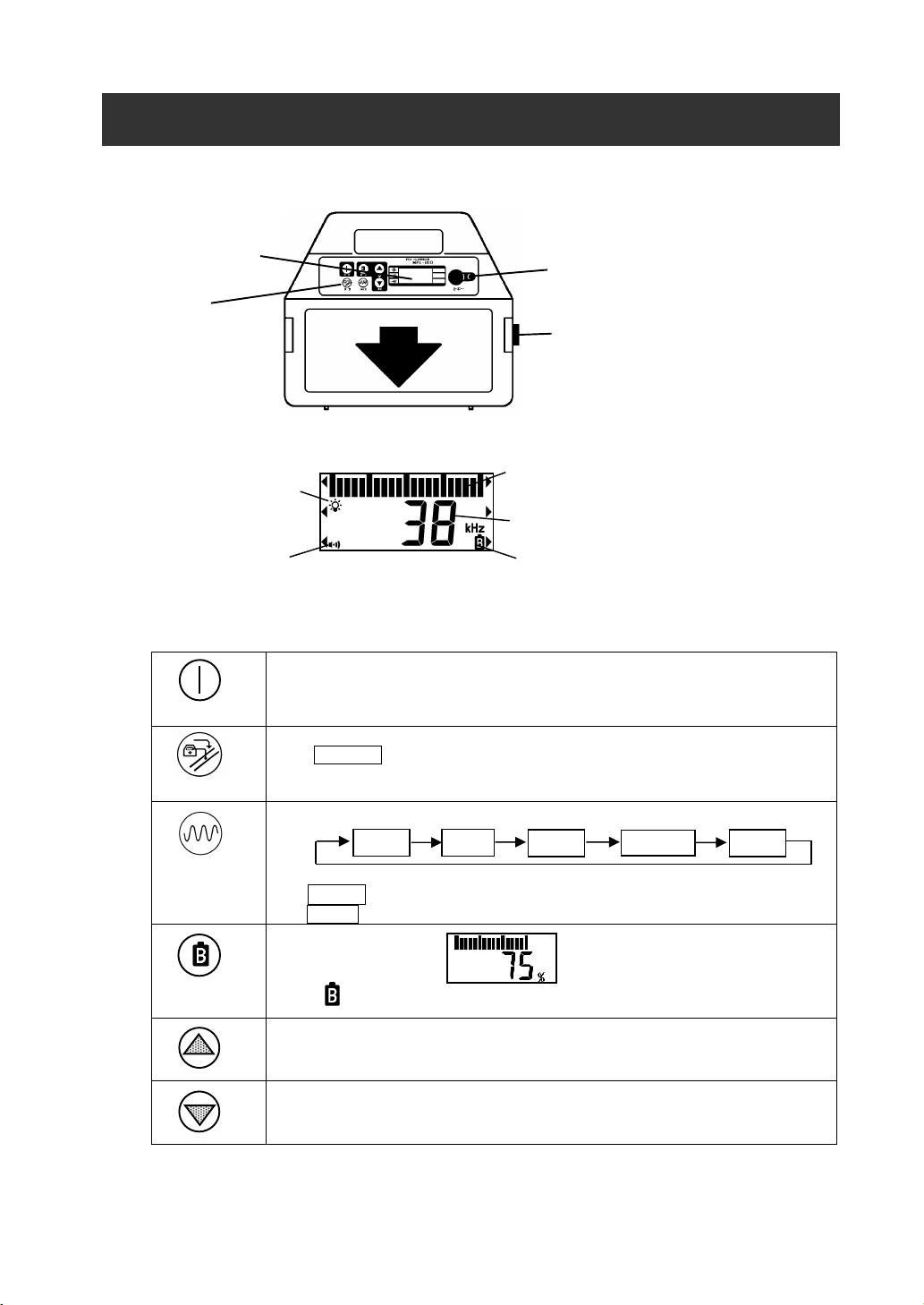
5. Description of parts & basic operation
Battery indication
5-1. Transmitter
LCD Window
Touch pad
1) LCD window
Backlight On / Off
2) Key function
POWER
ADJUST
FREQUENCY
8-pin connector
Battery compartment
Bar-graph (Output power / Battery status)
Power ON / OFF
*Each time Transmitter is turned on the batteries are automatically checked.
Press ADJUST key after hook up to automatically adjust power.
80kHz
38kHz
9.5kHz
9-38kHz
*1
*1 9-38kHz : Broadcasts both frequencies simultaneously in direct mode only.
*2 512Hz : Direct mode only
*2
512Hz
MODE
Battery indication
*The symbol appears when battery is low.
Increase Output power
Reduce Output power
- 7 -
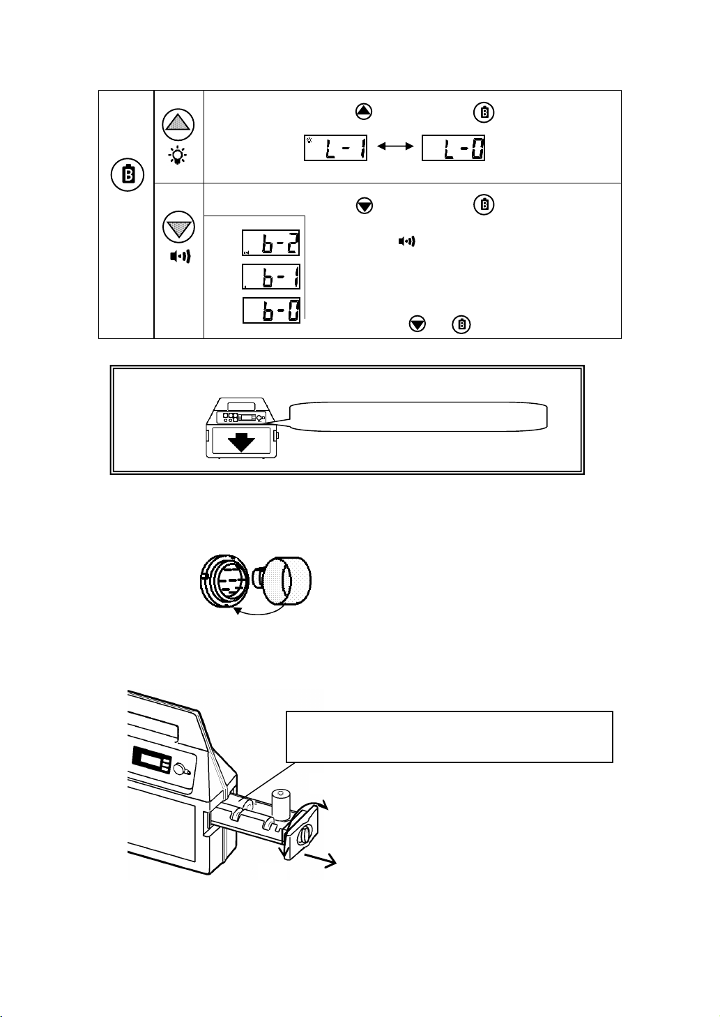
Press and hold
& for 2 seconds.
MODE
Light On/Off set
Sound set
: Press
Light On
: Press
: SOUND ON
: TRANSMITTER SOUND OFF, FUNCTION SOUND ON
: SOUND OFF.
key while holding
key while holding
Note : The last setting is memorized after the unit is Turned OFF
Transmitter sound :
Beep…(15sec.)…..Beep…(15sec)…Beep
3) 8-pin connector
The Direct connection cord or the External coil cord are plugged into the 8-pin connector.
Put the rubber protector on
when not in use.
4) Battery compartment
Replace all batteries when there is a low battery condition.
Use 8 3 1.5V alkaline type D (LR20 / 13A) batteries.
ALWAYS CHECK THE BATTERY POLARITY BEFORE
CLOSING THE COMPARTMENT
Close
Open
(MODE).
Light Off
(MODE).
- 8 -

5-2. Receiver
Power ON / OFF
Adjusts Signal sensi
tivity for PEAK MODE.
Depth measurement
Receiving sensitivit
y
20%
20%
30%
30%
Power Peak / Null Mode
Battery
compartment
1)Key function
Power
Measuring Mode
RS232C
Connector
Earphone plug
Signal input terminal
(8-pin connector)
*Power save function: Automatically power off after 5 minutes of inactivity.
Gain Adjust Depth / Current Frequency
Bar-graph
Receiving sensitivity
Frequency
Battery indication
Gain
Adjust
Depth /
Current
Peak / Null
Press GAIN key
100% - 100%
30%
Peak value spot = Top of the line
70%
50% 50%
Magnetic
field
Press GAIN key
Note: 100% is not the maximum peak value. When 100% appears, press Gain key again
until a new sharp peak value is obtained, that is not 100%.
: Press DEPTH key at the peak value spot.
Selects locating mode.
Peak Mode
Depth
Current index : Details page 25
Note: Current index is not displayed if probe is used.
Peak mode :Maximum sensitivity is the point directly
above the object line.
Null mode : Minimum sensitivity is the point directly above
Null Mode
the object line. The buried object line is
indicated with arrow.
- 9 -

Various settings
Frequency
Mode
Selects operating frequency.
80kHz
38kHz
9.5kHz 512Hz
* 50Hz * 100Hz
60Hz 120Hz
RAD
Selects Power frequency 50Hz / 60Hz
*RAD : Radio (passive 9kHz to 33kHz)
Power on while holding Frequency key.
POW 50Hz or POW 60Hz screen is indicated in 1 seconds.
Press Frequency , and select 50Hz or 60Hz .
At the same time, 100/120Hz is selected. ( 50Hz Þ 100Hz / 60Hz Þ 120Hz )
The setting is memorized with Power off.
1. Selects sound and backlight options. By pressing Mode , move on.
Press Gain : Select speaker sound On / Off.
S-ON : SOUND ON
S-OF : SOUND OFF
Press Depth : Select backlight On / Off.
L-ON : LIGHT ON
L-OF : LIGHT OFF
2. Selects Depth function. By pressing Mode , move on.
Press Depth : Select depth function 0-5m / 0-10m ( 0-16ft / 0-30ft.).
*0-5m / 16ft : Applied for Inductive mode.
Detecting near t he end of the pipe.
Depth measurement range 0 to 5m(16ft).
CAUTION
When applying Inductive mode, select 0-5m /16ft . Depth measurement
error gets bigger at near the Transmitter when 0-10m/30ft is applied.
*0-10m / 30ft : Applied for the depth deeper than
5m(16ft.) , near guardrail or metal fence.
The measurement range of depth 0 to 10m(30ft).
3. Selects PROBE detection. By pressing Mode , return to measurement.
When Sewer or Mini Probe is employed for the detection of Non-metallic pipe or Boring device.
Only 38kHz and 512Hz are used for Probe.
Press Frequency : Select detecting function .
PROB ON .
Probe detection
PROB OFF .
Cable / Pipe detection
*The last setting is saved.
- 10 -

Mode
Setting the Time and Date
a)Power on while holding Mode , wait for clock display appears.
The year will flash.
Press Gain to advance the year or Depth to decrement the year.
b) Press Mode , the month will flash.
Press Gain to advance the month or Depth to decrement the month.
c)Do same as above to set Day - -> Hour - - > Minute.
When measurement starts, setting is completed.
2) Battery compartment
Replace all batteries when there is a low battery condition.
Use eight 1.5V alkaline type AA (IEC LR6/NEDA15A).
Close
Open
ALWAYS CHECK THE BATTERY POLARITY
BEFORE CLOSING THE COMPARTMENT
3)RS2332C connector
A RS232C connector is provided for serial communications
to the personal computer.
*Interface cable is supplied as option.
*Specification of interface cable :
9-pin, D-SUB, straight connection
or same specification RS232C-USB conversion cable
Interface cable is available at market.
4)Earphone plug
Earphone can be used in a noisy area.
Supplied as an option.
5) 8-pin connector
Used with External Coil (9.5kHz or 38kHz) to find wiring
systems in a building or overhead telephone cables.
External coils are supplied as options.
Battery 100%
Battery 0%
When the batteries tray is stored, check the
ARROW should point up.
Earphone plug
8-pin connector
- 11 -

6. Warning Message
*Messages during your search procedure :
OVER
LOW
Receiving signal is too high.
a) Indirect mode : Transmitter and Receiver are too close each other.
b) Other cases : Reduce output of the Transmitter.
Receiving signal is too small or not present.
a) In the case of direct, induction or coil
- Increase output of the Transmitter.
- Check batteries, connecting parts and frequency of the Transmitter.
- Check signal loop at the Transmitter.
b) In the case of Radio / Power mode
- There are no conductors to radiate magnetic fields. There is no pipe or cable
- There is a conductor, but the signal is too low to adhere to the line. Use Transmitter
to search for the line.
*Messages on location :
PUSH
GAIN
Press GAIN key. Þ Normally this is your object line.
Reduces or increases signal strength.
*Messages on Depth measurement :
ERR
16. --ft/in.
5. --m
30. --ft/in.
10. --m
a) Received signal level is unusual, or received signal is too small.
b) Located point is not right above the object line.
c) Metallic fences, metallic structures or cars are interfering with the depth
measurement. Find area with less interference.
d) The Line is disconnected.
Indicating that the depth measured is deeper than 5 m / 16 ft.
In Line detection (0-5m / 0-16ft.) mode, locator cannot read below this depth
Indicating that the depth measured is deeper than 10m / 30ft.
In Line detection (0-10m / 0-30t.) or Probe detection mode, locator cannot read
below this depth.
- 12 -

Mode of Detection
Purpose of usage
7. Operation of Transmitter (TX)
Direct Connection Mode
Signal
External Coil Mode
Indirect (Inductive) Mode
Used with External Coil to find wiring systems in the building.
Building Wiring
Signal
Signal
This is the best way to inject AC current direct to the target line.
Signal (AC current) will return to the Transmitter through the
ground.
Black clip
Ground stake
Effective for detecting the target line in congested areas.
Advantage for live power or cable, that is not accessible for
Direct connection.
The clamp is waterproof and will attach on any size cable.
No need for a ground stake.
Effective for detecting the target line in congested area.
The target line must be grounded.
If there is no direct access to the target line, use this method.
The Transmitter can induce its signal to the buried line.
Place the Transmitter in an upright position and at right angle to
the buried line.
Minimum TX to RX distanceÞ30 ft / 10 m
Note: When using the indirect mode, set the depth mode of the receiver
to 0-5m (0-16ft.) .Depth measurement error gets bigger at near the
Transmitter when 0-10m (30ft) is applied.
TX's circuit is protected* up to 250V at 50 / 60 Hz.
*512Hz output is cut off automatically.
Transmitter
Ground
Red clip
Target line
Probe Mode
Used for tracing small diameter drains or plastic pipes.
Also, pinpoint a drain blockage or collapse. Can trace nondirectional boring tools.
The Probe is available in two sizes,
20mm/ 0.79" and 50mm / 2" diameter.
- 13 -

7-1. Direct connection mode
When the clips are connected to the transmitter, Direct Connect
ion mode automatically selected.
Frequency setting
Connect the cable clips to the target line and ground stake.
Transmitter
length of cable from the reel.
Note:
Note: Clean off if the connected part is rusted or
A specific route can be detected in Direct Connection mode. Use two 5m/16.5 ft connecting cable with a
reel provided in the carrying case as one of the standard accessories.
This Groove up
Before connecting, pull out proper
Display of the Direct mode
Press FREQUENCY key
Red clip
Metal pipe
painted to ensure a good electrical connection.
Line
90°
*Set a receiving frequency on the Receiver the same as
the transmitter.
Receiver
Press Frequency key
Black clip
Ground stake
Check the grounded point. Find the best place to
ground to have a GOOD SIGNAL LOOP
indication.
Place the Earth/Ground as far as possible and at right
angle to the object line.
Keep Receiver at least 5m/16ft. away from the signal
connection point as illustrated
- 14 -

Check the signal loop
Adjust output power
Check the voltage when connecting clip to Power line.
Note:
AC VOLTAGE
DANGER
When signal loop is acceptable, Beeping sound is emitted.
P P P P ….
Beeping sound is emitted after output is adjusted when the resistance value of the cable is high.
Automatically adjust power
Press ADJUST key.
*When “GOOD SIGNAL LOOP” isn't indicated after pressing ADJUST.
Þ Clean off the connected part if rusted or painted or move ground stake.
When output is adjusted
*When the Receiver indicates “ OVER” , Press
*W hen locating a long-distance line or deeper depth than 3m / 16ft., Press
key. Þ Reduce output.
*Transmitter will beep for 30 seconds.
*Sound stops when Press ADJUST key.
*Sound setting is [b-0].ÞBeeping sound off.
GOOD
SIGNAL LOOP
key. Þ Increase output.
- When voltage is greater than 20 volts, voltage is displayed.
- When voltage is greater than 25 volts, Alarm sounds.
Note: 512Hz output is cut off automatically.
ELECTRIC SHOCK
Death or serious injury will result. 250 Volts maximum across
clips. Use protective equipment.
PEEEEEE!!!!
*Alarm stops when Press ADJUST key.
*Sound setting is [b-0]. Þ Alarm off.
- 15 -

Direct Connection mode
Use the Receiver 5m / 16ft. away from the
Applications (1)
Applications (2)
DAMAGE TO APPLIANCES, FIRE OR EXPLOSIONS.
WARNING
at
No need of ground at the ending point
transmitter and clips.
5m / 16ft. away
Power cable:
Disconnect common ground lead and
connect the Red clip to Power line ground
lead. Then locate Power line
Telephone cable:
Disconnect Telephone
Ground lead and connect
the Red clip to it to locate
Telephone line.
Remember to correctly reconnect common grounds for telephone, CATV and Electric Lines.
Check Local codes for proper grounding procedure. IMPROPER GROUNDING MAY CAUSE
Telephone cable
Power cable
House meter
CATV cable:
Disconnect CATV's
ground lead and connect
the Red clip to it to locate
CATV line.
Common ground lead
CATV cable
If the dead cable is the object, connect the red alligator clip of the connecting cable to either the aluminum-sheath
or a bundle of the copper cores directly.
Short distance dead cable
Long distance dead cable
The ground should be provide
the end of the line
- 16 -

7-2. External coil mode
When the External coil is connected to the transmitter, External coil mode is automatically selected.
Frequency setting
Adjust output power
Connect the External coil to the target line.
Note :Make sure it is attached parallel and in line with the cable as illustrated.
power
increase output
Use 9.5 kHz, 38 kHz or 80kHz External coil supplied as an option. Use this mode if object is accessible.
An induced current, generated by the coil in the External Coil attachment, is applied directly to the exposed
part of the cable / pipe to be located.
Applicable to : Live Telecom cable or Live Power cable. Fiber optic cable having an aluminum-sheath.
This Groove is up
External Coil mode indication
External coil
Frequency is selected based on coil used
with the External coil automatically.
When 38kHz coil is
connected
Reduce output
power
Electromagnetic field
Telecom / Power cable
(Diameter up to 10cm / 4”)
Transmitting coil
*Set a receiving frequency on the Receiver the same
as the transmitter.
Press Frequency key
Indicate output power with the bar
graph and the numerical value when
pressing / key.
*The jaws do not have to be closed around the cable.
(This coil method is different from the conventional clamp
that must have jaws perfectly closed. Different size clamps
are not needed. The Verifier coil method uses the indirect /
Inductive principle.)
- 17 -

External coil mode
Make sure that the cable is grounded at both ends.
Note : Do not attach to the metal pipe or metal riser above the ground.
Note :
Use the Receiver more than 5 m/16 ft away from the coil clamp
OK
Note : Fresh water has no effect Locating the cable or detecting depth.
will not trace.
Do not put the coil close to or around the ending or middle ground.
Signal to ground
Intermediate ground
* If the cable is submerged in water, you can use the coil attachment in the water.
The coil attachment is WATERPROOF.
Attach the coil clamp to the cable/PVC part.
Brash or salt water will effect locating.
PVC Pipe
Metal Pipe
Cable
when starting the location work.
5m / 16 ft. away
- 18 -

7-3. Indirect (Inductive) mode
When nothing is connected to the transmitter, Indirect mode automatically selected.
Frequency setting
Place the transmitter over or near the area to be located.
tic
90
90
°
Transmitter
If there is not direct access to the object line, the Transmitter can apply AC current ( signal ) to
the line directly below the Transmitter.
Note: When using the indirect mode, set the depth mode of the receiver to 0-5m (0-16ft.) .
Electromagne
field
Press FREQUENCY key
POWER
*Set a receiving frequency on the Receiver the same
as the transmitter.
Press Frequency key
Indirect mode indication
Do not place the Transmitter on a
manhole cover or other steel covering.
*Place the Transmitter in an upright position at a 90° angle to the object line as illustrated.
°
Object line
Object line
Top view
*Location the area of a manhole, place the Transmitter on the side of the manhole you wish to locate.
Transmitter
signal
signal
manhole
- 19 -

Adjust output power
Note :
Use Receiver
more than
10m / 30ft. away from Transmitter
Receiving
Indirect mode
Reduce power
Increase power
Indicate output power with the bar graph and the numerical value when
pressing / key.
*Standard of adjustment.
- When depth is less than 0.6m / 2ft. Þ 50% ~ 60%
- When depth is more than 0.6m / 2ft., less than 1.5m / 5ft..Þ 70 % ~ 80%
- When depth is more than 1.5m / 5ft..Þ 90 % ~ 100%
Note: If output is adjusted to 100%, you can usually locate in any place.
But the battery of the transmitter is redused as output increases.
when starting the location work or an "Air Coupling"
between the Transmitter and Receiver can exist.
More than 10 m / 30ft. away
Note: Detection of the Multiple Telephone Cable Pipes
(Metal Ducts) in Indirect mode
Don't assume that the peak point of the signal
strength obtained is the center of the multiple lines.
It is the central point of the electromagnetic field
applied by the Transmitter.
sensitivity
- 20 -

Start
ing Null Mode
To find the direction of the object line,
To find the position of the object line,
Move the Receiver from side to side to determine
Peak = Direction of
8. Operation of Receiver (RX)
230
310
450
When Receiver is passed the top of the line,
550
200
150
40
30
Number of receiving
Move in the direction of
the arrow.
8-1. Null Mode
Press Peak / Null key.
Null Mode
level is blinked.
the exact position.
Pinpoint the position.
Is displayed
The direction of
the object line.
Receiving level
Same as Depth distance
approximately
Do not swing like this.
The arrows are indicated on
the both side.
rotate the receiver and stop at the position of the
maximum receiving level.
Receiving level
the object line
It is ghost signal if the
arrow is reversed.
when number is blinked
Same as Depth distance
approximately
Object Line
Beep sound is emitted.
PE!
Object Line
- 21 -

Start
ing Peak Mode
To find the direction of the object line,
When
“
PUSH GAIN
” appears, pre
ss Gain
Adjust
key until maximum peak value (not 100%)
To find the position of the object line,
Peak = Direction of
30%
20%
100% 100%
70%
30% 30%
- - -
- - -
0%
0%
8-2. Peak Mode
Press Peak / Null key.
Peak Mode
is displayed.
30%
Number of receiving
level is not indicated.
Receiving level
30%
When 100% appears…
When PUSH GAIN
appears…
Same as Depth distance
approximately
rotate the receiver over the object line and stop at the
position of the maximum peak value.
Is displayed
the object line
70%
50%
Press Gain Adjust key.
70% appears as an initial receiving level.
Note: 100% is not the maximum peak value.
Maximum (peak) value, the precise position and direction, are obtained
when the Receiver blade is the top of the object line
Number of receiving
level is not indicated.
Same as Depth distance
approximately
Object Line
70%
50%
- 22 -

8-3. Depth measurement
90
°
90°
Axis
Signal is too small / too high.
*Warning message
Data
Once the precise location of the object line has been determined, the Depth key is pressed to display
the distance from the Receiver's blade to the object line. Calculations are indicated on the digital display.
Note: Depth reading is a calculation of received signal strength.
Hold the Receiver vertically, place the blade on the
ground and do not move it during the depth
measurement.
Blade
Center
Depth
Object line
Press Depth / Current key.
Normal calculation
Depth
Indicate depth mode
Current index
Data Logging
Press Mode key.
Press Gain Adjust key.
Memorized Depth, Current index,
Date, time and frequency.
number
Start Tracing
Touch the ground with the Receiver's blade at an
upright position.
If the ground slopes, keep
the Receiver at right angles
to the axis of the globe.
Deeper than 5m / 16ft.
ERR appears….
*Receiving signal is not strong enough.
- Possibly this is the wrong line.
- Move the Receiver again from side
to side to find the exact position.
*Gas pipe Þ if not well jointed
- injected signal does not travel well
- receiving signal is too small
- 23 -

8-4. Logging Data
to
*Cable for PC communication
Indicate the Logging data
1) Press Mode key.
2) Press and hold Peak / Null .
for one second.
3) Press Gain Adjust - Increase data number. Press Depth / Current - Decrease data number
4) Two seconds after data is displayed., its stored date and hour is displayed automatically in order.
Delete Logging data
Press and hold Frequency .
key for two seconds..
Speaker and backlight
setting screen appears.
Depth Data
Data number
CAUTION : If delete operation is done, all data is gone.
Takes several seconds
delete data.
The data recorded at
the end is indicated.
Return to locator function
Download data to the PC
Connect the cable to the
RS232C connector on the
Receiver.
is supplied as option.
Press Mode key.
Return to locator function
Press Mode key.
Refer Data viewer soft manual about operation of
data communication with a PC.
Data communication
screen appears.
- 24 -

8-5. Current index (Current measurement)
What
’
s the Current index?
When
sudden
ly current drop…
The Current value is not affected by the depth
!!
Each time a Depth calculation is taken, a Current Index simultaneously appears on the display.
*Current index Current Value (mA)
Depth : 1.90m
Current Index :200
Depth : 1.75m
Current Index :150
Depth : 2.00m
Current Index :100
Current Value =1.5mA
Current Value =2.0mA
*Normal tracing ® Current value progress down.
*The Current gradually reduces as the distance from the Transmitter increases.
The current leaks to a ground.
1.00m / 200
1.00m / 50
ERR : The line is disconnected.
Or, the current does not travel after the joint of the gas line / water line due to the
non-conductivity.
Current Value =1.0mA
1.00m / 10
Disconnect
Leak/ Fault
1.80m
70
0.7mA
ERR
??
The current value is not affected by the depth,
but it is affected by the detection methods, the
frequencies and power level.
- 25 -
1.00m / 200
1.30m / 200
30cm

The Current index helps to confirm the line's identity.
If an adjacent line is running parallel with the object line.
If two
lines are crossing:
Locating T connection
Current index:260
0.5m
A with a 260 current index
Current index:
150
Current index:
50
Current index:
100
Current index:200
Current index:50
Receiving
sensitivity
Current index:70
1.5m
The line with the highest current index is the object line into which the signal is being broadcast.
ÞLine A with a 200 current index is the trace object.
1.5m
Line: A
Depth :1.50m
Line: A
Depth :0.50m
0.5m
Line: B
Line: B
Line: B
Depth :0.50m
Depth :1.50m
Line: A
Lineis the object line.
Even though signal is smaller.
Þ Splicing/jointing points of Power cable, Telephone cable, Gas pipe, Water pipe, or Sewer pipe.
Main line-A with a 200 current index
Line-B : Index value 150 Þ Main line
Line-C : Index value 50 Þ Branch line
A
- 26 -
Depth :1.00m
B
Depth :1.50m
C
Depth :1.50m

8-6. Passive mode
cable.
The Power and Radio passive modes of the Receiver are used to search an area for unknown power
cables and other utility lines, without the use of the Transmitter.
Frequency setting
Press Frequency key.
How to choose 50/ 60Hz
Power on while holding Frequency key. POW 50Hz or POW 60Hz screen is indicated in 1 seconds.
Press Frequency , and select 50Hz or 60Hz .
At the same time, 100/120Hz is selected. ( 50Hz Þ 100Hz / 60Hz Þ 120Hz )
The setting is memorized with Power off.
Auto search function of Magnetic field in nature (Radio wave)
When applying Radio wave (RAD) detection, the most sensitive frequency is selected with auto search function.
Search all frequencies
Set frequency to RAD , Press and hold Gain Adjust for one second. And then, search starts.
Press Gain Adjust key.
Search frequencies in several bands
Press Gain Adjust during search, Search stops. Resume search, the search starts from the halted frequency.
Frequency
9.1kHz
Search starts
Above mentioned example shows the first search detects the most sensitive frequency from 9.1k to 17kHz. And then search is
halted. Then, search resumes. The second search detects the most sensitivity frequency from 17k to 32.8kHz
Applying this function, several different kind of cables can be detected in several stages.
Power mode: Power mode detects 50/60 Hz or
100/120Hz frequency radiated by the live power
Radio mode: It locates buried utility lines as they
reradiate very low frequency,
Search start
Frequency
17.0kHz
Search stops
Frequency
17.0kHz
Resume search
Search end.
Frequency
32.8kHz
Search stops
Select
60Hz / 120Hz .
or
50Hz / 100Hz .
Select RAD .
Automatically selected the
most sensitive frequency
Frequency
9.1kHz
Search starts
- 27 -

Decide the place of the starting point. Press Gain , locate that circumference.
WARNING
Streetlight
When street light is
lighting, 50/60Hz is
available.
Close the Receiver to
the lead-up cable.
RAD auto search is
effective.
Power /
telephone
Trace a line from the starting point to have sensitivity.
Depth measurement Press DEPTH key after pinpointing the location.
manhole
Press Depth / Current key.
Accuracy of the depth measurement using the passive modes is unreliable.
Always expose the utility lines by carefully hand digging before excavation.
- 28 -

8-7. Building wiring
Receiver
Transmitter
Tracing the wire
chment picks up the signal and the current
Note: The depth is not displayed.
DANGER
A stiff piece
It is possible to detect the wiring in a building by broadcasting the Transmitter signal into the
wiring. For searching, use the External coil, supplied as an option, which is connected to the
Signal input terminal (8-pin connector ) of the Receiver.
Connect the External coil's plug to the Signal Input Terminal (8-pin connector) on the Receiver
Connect the External
coil's plug
Set the frequency same as the Receiver.
Press FREQUENCY. key.
The clips are connected to the transmitter.
Connect the red clip to the
conductor on the plug.
Press Frequency. key.
‘+’ appears
Set a frequency on the receiver
same as the External coil.
Always check that the Transmitter, the
Receiver and the External coil are at the
same frequency.
Neutral
Connect the Black clip
to a ground stake.
of wire
ELECTRIC SHOCK
Death or serious injury will result. 250 Volts maximum across clips.
Hold the External coil near the wall as illustrated.
The coil in the External coil atta
strength (=receiving sensitivity level) is displayed on the LCD.
Receiving Sensitivity
Coil needs to be
perpendicular to wire
- 29 -

8-8. Probe for non-metallic pipe
Battery check
Replacement of batteries
Output setting
Mini-Probe
(+) (-)
A Probe, supplied as optional equipment, is a small waterproof transmitter emitting a signal that is traced by the
Receiver.
The Probe can only be used in the non-metallic pipe.
Note : The metal pipe conceals a signal so that the Receiver cannot detect the signal. Use Direct connection mode.
a) Set the rotary select switch to BATT.
b) Check if the green lamp is ON.
c) If the lamp is OFF, replace all batteries with new ones.
a) Unscrew the top cover and open the battery compartment.
b) Four 1.5V AA (LR-6, NEDA15A) batteries are placed in series.
c) The proper polarities for the batteries are shown on the battery holder.
a) OUTPUT LOW: 0.7 ft to 5.8 ft ( 0.2 m to 1.8 m ) Þ less than 4ft / 1 m
b) OUTPUT HIGH: 5.9 ft to 16 ft ( 1.8 m to 5 m )Þ more than 4 ft / 1 m
Attach the Sewer probe to the rodding tool and
insert the probe into the pipe.
Attach the Sewer probe to the Pulling eye with the
pulling wire and pull the probe with the wire.
PT3/8” (Pitch 3/8”)
Lamp
Small probe for 1" Fiber optic duct or non-directional boring tools
Replacement of batteries
Attach the Mini-probe to the Pulling eye
*Mini-probe doesn't have battery check function.
Check the transmission of the probe on the ground
before locating.
Attach the Mini-probe to the rodding tool
M10(mm) thread
- 30 -

Near the direct above the Probe, arrow
Away from the direct above the Probe,
Tracing a non-metallic drain or plastic pipe with the Probe.
Ex. Feed the Probe into the PVC pipe and locate
the blockage or collapse
Receiver Þ Press Frequency key to set 38kHz or 512Hz .
Set the detection mode to Probe mode.
Press Mode key three times
Press Frequency key
PROB OFF
Pipe & Cable mode
PROB ON
Probe mode
Location measurement
( horizontal direction of the line)
Apply Peak mode. Horizontal direction
can not be detected with Null mode.
Use the Receiver right angle to the object
line like the drawing
Location measurement (Same direction in the line)
Peak mode.
Three sensitivity peaks appears.
The biggest peak is the point direct
above the Probe.
Null mode
indicates the direct above the Probe.
the receiving level flashes and the
arrow indicates opposite direction.
Depth measurement Þ Press DEPTH key
* For the Sewer probe :
* If tracking a boring tool, Probe should be housed in a metal housing with slots milled in housing to
allow signal to escape. Location is done as above.
OVER Þ Change the output to OUTPUT LOW.
LOW Þ Change the output to OUTPUT HIGH.
Depth
Current index is not displayed.
- 31 -

Keep more than
Metal fence
Footbridge
9. Precautions and applications (At the locating site)
1) Locating Work Near the Guardrail (In Indirect mode)
Object line
2) Metal Fences or Other Metallic Structures
1m/3.4ft away
Locating with the Receiver next to the
guardrail will give an incorrect reading.
Locate just between the breaks of the
guardrails.
Keep more than
2m/7ft away
- 32 -

3) Street Light, Traffic-Control Sign
Keep more than
1m / 3.4ft away
4) Power-Transmission Tower
5)Telephone / Electric Power Poles
Keep more than
10m / 30ft away
Keep more than
1m / 3.4ft away
The transmitter can be
placed next to the pole.
Keep more than
1m / 3.4ft away
There is no interference
from Power lines above.
- 33 -

6) Heavy Traffic Flow
7) Railroads
Keep the receiver more
than 2m/7ft away
Locate when traffic has passed.
Within 1m / 3.4ft
Stop locating when a train is
approaching
Keep the receiver more
than 2m/7ft away
- 34 -
Stop!
OK !
OK !
OK !

Call & Contact
TAKACHIHO SANGYO CO., LTD.
Tokyo office
19-6, 5-Chome, Shiba, Minato-Ku, Tokyo 108-0014 TEL 81-3-3453-4778
Head office & Factory in Nagoya, Japan
2007.10.1 495-082A
 Loading...