

Page 1
PARTS
LIST
TMCE-601
P-CP03-E
f~R07\
Page 2
Table of Contents
TMCE-601
•
TMCE-601
•
TMOE-601
•
TMCE-601
•
TMCE-601
•
TMOE-601
•
TMCE-601
•
TMCE-601
•
TMCE-601
•
TMCE-601
•
TMCE-601
•
TMCE-601
•
TMCE-601
•
TMCE-601
•
TMCE-601
•
Part
Nos.
GENERAL VIEW
FRAME
STAND
MAIN SHAFT MECHANISM
ARM 1 ..............................................................................
ARM 2
X-AXIS DRIVE SYSTEM
Y-AXIS DRIVE SYSTEM
LOOPER•ATH
TENSION BASE • · ·
TENSION RELEASE
COLOR CHANGE SENSOR
THREAD
BORDER FRAME
ELECTRIC PARTS
of
screws,
.............................................................................
..............................................................................
....................................................
..............................................................................
........................................................
........................................................
...............
.. • · .. · .. · · • · · · .. · .. · · .. · · · .. · · · · · .. ·
STAND··········
nuts,
washers etc.are listed at the
.................................................................
................................................................
···
·•·
.................... · ......... · ....
.............................................................
.....................................................
....
· .. · ..
·······
..
·•·········
end
of
volume.
....
· · · · .. • · .. · · · .. ·
..
···
..
•······
•···
..
•····
·•
......
...
• ..
....
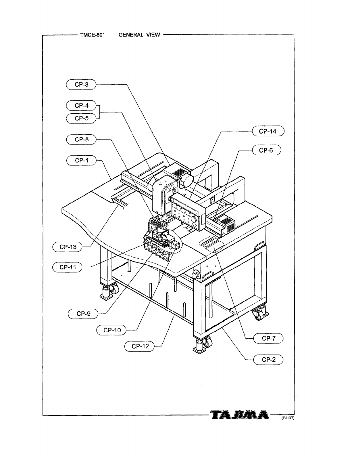
CP-1
CP-2
CP-3
CP-4
CP-5
CP-6
CP-7
CP-8
CP-9
CP-1
CP-11
·
CP-12
CP-13
CP-14
0
[ Explanation of Marks #'s and *
+Please specify,
embroidery space when you order us with the parts having****
Ex.:
in
the
TMFD-612
[Model]
following
's
at End of
manner,
your
(450x275)S
[Emb. Space]
Part
No.]
machine
model,manufacturing
No.Ol234
[Mfg.
No.J
at
the end
number
of
the part No.:
and
(BH07)
Page 3
r------
TMCE-601
GENERAL VIEW
----------------.
~----------------------------------------1r~--~
(BH07)
Page 4
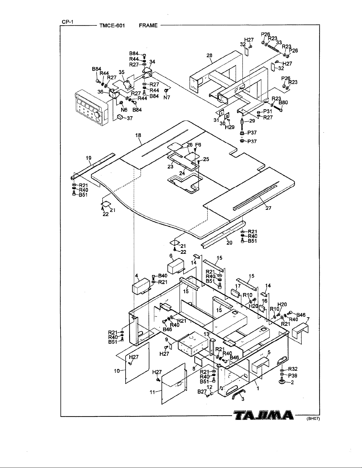
...,.:C_P_-1---
TMCE-601
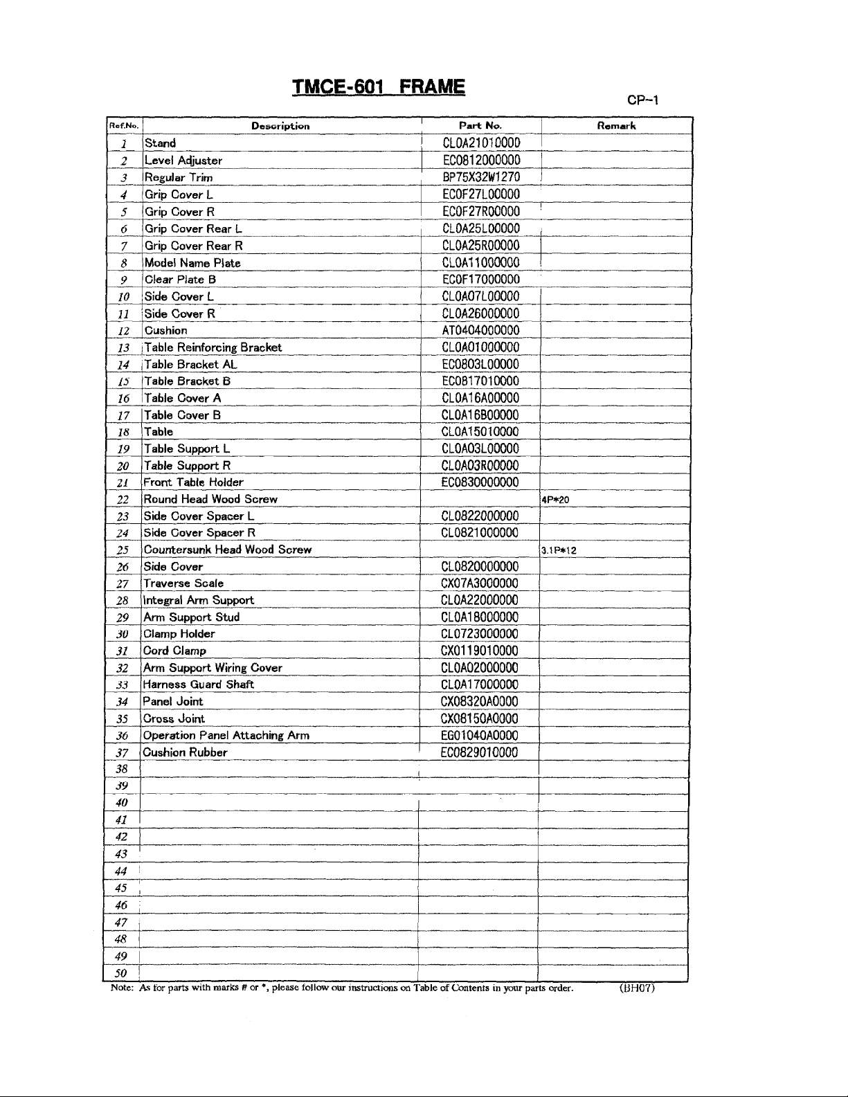
FRAME------------------------------------1
L_------------------------------1r~~--(~BH=07)
~
J,.-R32
&-.p39
~2
Page 5
Rcf.N<>.
Stand
1
Level Acljuster
2
Regular
3
Grip Cover L
4
Grip
5
Grip
6
Grip
7
Model
8
Clear Plate B
9
Side Cover L
10
\Side Cover R
11
Cushion
12
iT
13
iT
14
Table Bracket B
15
IT
16
Table Cover B
17
Table
18
Table Support L
19
Table Support R
20
Front Table Holder
21
Round Head
22
Side Cover
23
Side Cover
24
Countersunk Head
25
Side Cover
26
Traverse Scale
27
Integral
28
Arm
29
Clamp
30
Cord Clamp
31
Arm
32
Harness Guard Shaft
33
Panel Joint
34
Cross
35
Operation Panel Attaching
36
Cushion Rubber
37
Trim
Cover R
Cover Rear L
Cover Rear R
Name Plate
able Reinforcing Bracket
able Bracket
able Cover A
Spacer
Spacer
Arm
Support Stud
Holder
Support
Joint
38
39
40
41
42
43
!
44
45
I
46
I
47
i
48
49
I
50
!
Note:
As
for parts
w1th
TMCE-601
Des"ription
FRAME
I
i
AL
Wood
Screw
L
R
Wood
Screw
Support
Wiring
Cover
Arm
I
marks # or , please follow our mstructlons on Table
*
Part
No.
CLOA21010000
EC0812000000
BP75X32W1270
ECOF27LOOOOO
ECOF27ROOOOO
CLOA25LOOOOO
i
CLOA25ROOOOO
CLOA11000000
!
ECOF17000000
CLOA07LOOOOO
CLOA26000000
AT0404000000
CLOA01000000
EC0803LOOOOO
EC0817010000
CLOA16AOOOOO
CLOA16BOOOOO
CLOA15010000
CLOA03LOOOOO
CLOA03ROOOOO
EC0830000000
4P*20
CL0822000000
CL0821000000
3.1P*12
CL0820000000
CX07A3000000
CLOA22000000
CLOA18000000
CL0723000000
CX0119010000
CLOA02000000
CLOA17000000
CX08320AOOOO
CX08150A0000
EG01040AOOOO
EC0829010000
of
Contents m your parts order.
CP-1
Remark
(tlH07)
Page 6
..=.CP_-2
___
TMCE-601
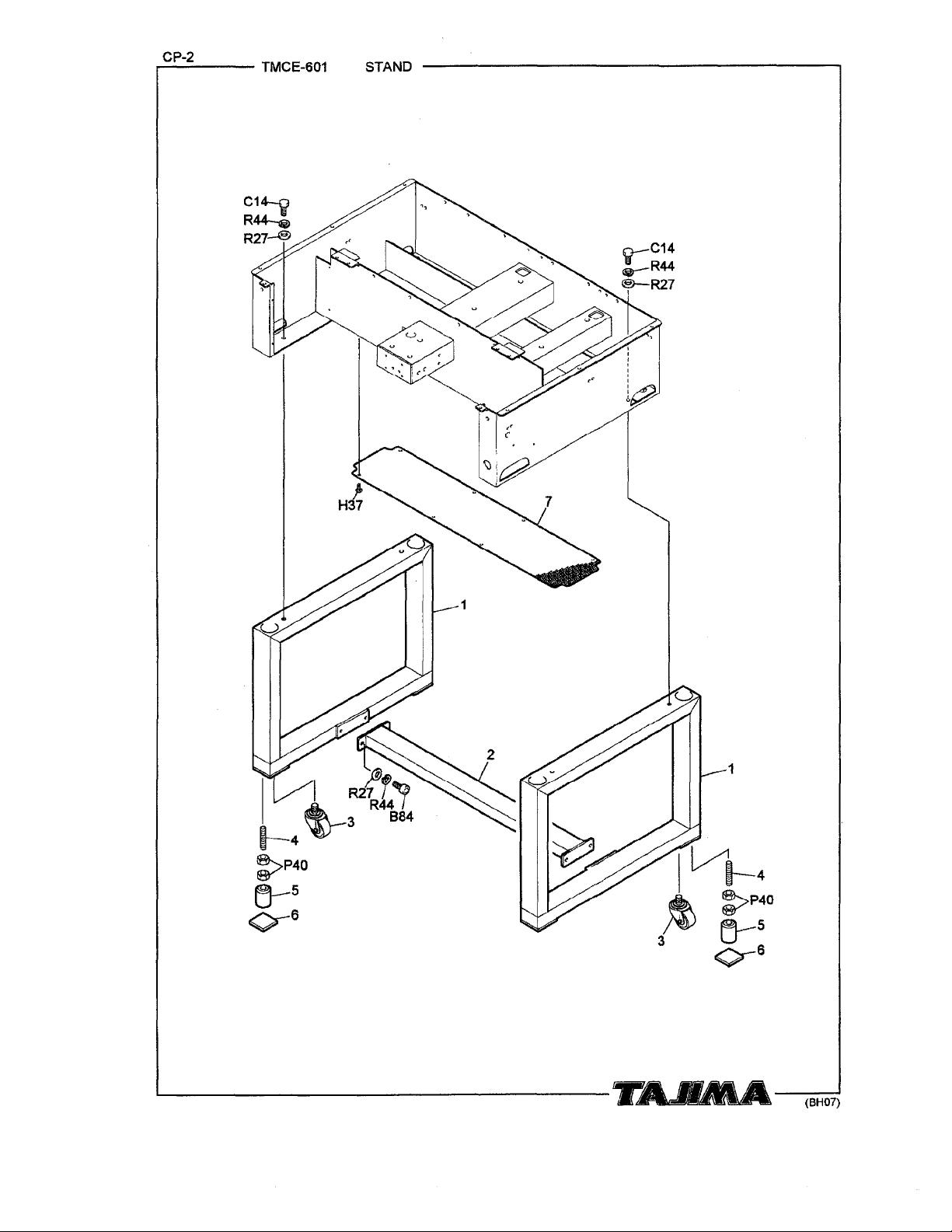
STAND
.
.
l
i~
I
L/'1-4
}t
3
1
:>P40
cr:
o-
(BH07)
Page 7
TMCE-601 STAND
CP-2
Ref.No.
Side Stand
1
Middle
2
Caster
3
Stud Bolt
4
Leveling Block
5
Vibration-preventive Rubber
6
Stand Bottom Cover
7
8
9
Stand
Base
Base
10
11
12
13
14
15
16
17
.
18
19
20
21
22
23
24
25
26
27
28
29
30
I
31
32
i
33
34
35
36
37
38
39
40
41
42
43
44
45
46
47
48
49
50
Note: As for parts
w1th
marks#
Description
..
or
*,please
I
i
:
follow our mstructtons on Table
Part
No.
ECOF03010000
EC0819020000
BP420SAR65f+1
CX08E3000000
CX08E7000000
EC0826000000
CLOA20000000
of
Contents
1n
your parts order.
Remark
I
:
:
l
(BH07)
Page 8
TMCE-601
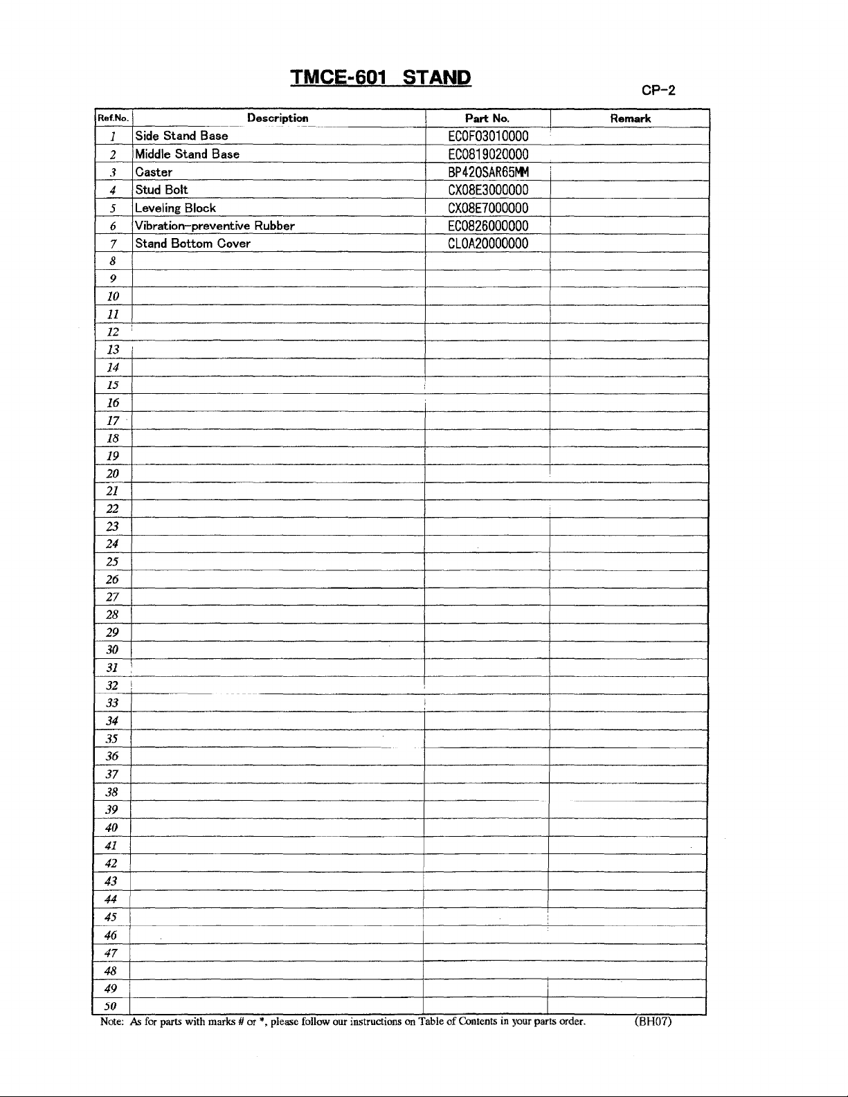
MAIN SHAFT
MECHANISM
7
Page 9

TMCE-601 MAIN SHAFT MECHANISM
CP-3
RDf.No.
jArm
1
2
3
4
5
6
7
8
9
10
11
12
13
14
15
16
17
18
19
20
21
22
Support Cover
Main
Shaft
Pulse (Stepping) Motor
Main
Shaft
Cover Stud B
Timing Belt
Main
Shaft
Cover Stud A
Main Shaft
15mm
Dia.
Bearing
Ball
Main
Pulley Positioning Collar
! Main Shaft Pulley
1Angle
1Angle
Angle Pointer
Encoder Base
Rotary Encoder
Nylon
Thread Stand
Case
Bearing
Shaft
Indicator
Indicator Plate
Clamp
23
24
25
26
27
28
29
30
31
32
..
33
34
35
36
37
38
39
40
41
42
43
44
45
46
47
48
49
50
Note:
As
for parts
With
Description
Motor
Base
Drive Pulley
Cover
Bearing Collar
A
Bushing
Plate
Base
Plate
Attaching
marks#
or*,
Stud
please follow our mstructJons on Table
Part
No.
CLOA08010000
CLOA19010000
CL6201000000
CL0589000000
CLOA06B10000
BPS5M1504250
CLOA09000000
CLOA06AOOOOO
CLOA04010000
EG0227000000
CL0548000000
BP6803ZZOOOO
CL0551010000
CL0591000000
CL05BB010000
CL0584000000
CL0582000000
CL0587000000
CL0586000000
CL0851000000
PB001100EBOO
MX0821020000
I
i
of
Contents m your parts order.
Remark
(BH07)
Page 10

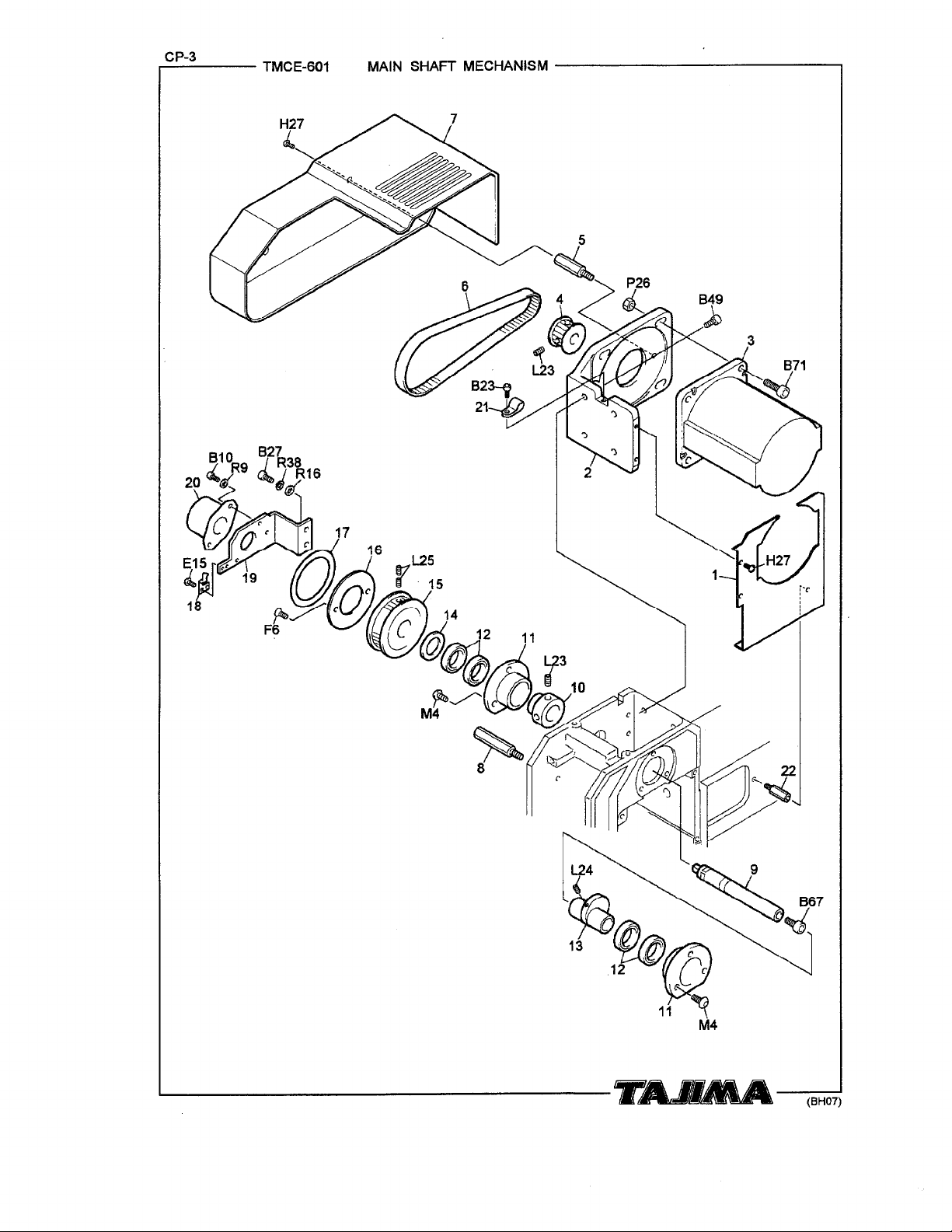
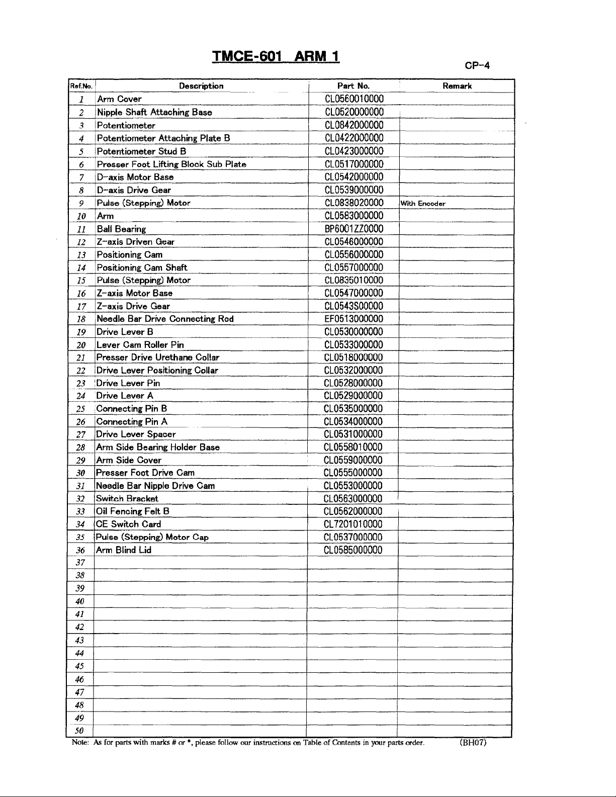
TMCE-601 ARM 1
827~
R3R
111
R1a::
4 5
~~u
3
36
(f)
R12~:.}
829
~'
6
62~~::8
M34
~
E1S......cf
827
R38
v
R12
\..
~~
9
11
12 '
~~
4
C'.~
~
~
L24
13 u
~
~14
~
1
1
~
Page 11
Ref.
No.
Arm
1
2
3
4
5
6
7
8
9
10
11
12
13
14
15
16
17
18
19
20
21
22
23
24
25
26
27
28
29
30
31
31
33
34
35
36
37
38
39
40
41
42
43
44
45
46
Cover
Nipple
S~aft
Attaching Base
Potentiometer
Potentiometer Attaching Plate B
Potentiometer Stud B
Presser
D-axis Motor Base
D-axis Drive Gear
Pulse (Stepping) Motor
Arm
Ball
Z-axis Driven Gear
Positioning Cam
Positioning Cam Shaft
Pulse (Stepping) Motor
Z-axis Motor Base
Z-axis Drive Gear
Needle Bar Drive Connecting
Drive Lever B
Lever Cam Roller Pin
Presser
Drive Lever Positioning Collar
~Drive
·Drive Lever A
:Connecting Pin B
Connecting Pin A
Drive Lever
Arm
Arm
Presser
Needle Bar Nipple Drive Cam
Switch Bracket
Oil
CE
Pulse (Stepping) Motor Cap
Arm
Foot Lifting Block Sub Plate
Bearing
Drive Urethane Collar
Lever Pin
Spacer
Side Bearing Holder Base
Side Cover
Foot Drive Cam
Fencing Felt B
Switch Card
Blind
Lid
47
48
--
49
50
Note:
As
for parts With
marks#
TMCE-601 ARM 1
Description
Rod
or*,
please follow our mstructJons on Table
Part
No.
CL0560010000
CL0520000000
CL0842000000
CL0422000000
CL0423000000
CL0517000000
GL0542000000
CL0539000000
CL0838020000
With Encoder
CL0583000000
BP6001ZZOOOO
CL0546000000
CL0556000000
CL0557000000
CL0835010000
CL0547000000
CL0543SOOOOO
EF0513000000
Cl0530000000
GL0533000000
CL0518000000
CL0532000000
CL0528000000
CL0529000000
CL0535000000
CL0534000000
CL0531000000
CL0558010000
CL0559000000
CL0555000000
CL0553000000
CL0563000000
CL0562000000
CL7201010000
CL0537000000
CL0585000000
of
Contents m your parts order.
OP-4
Remark
(BH07)
..
-
Page 12
CP-5
.....------
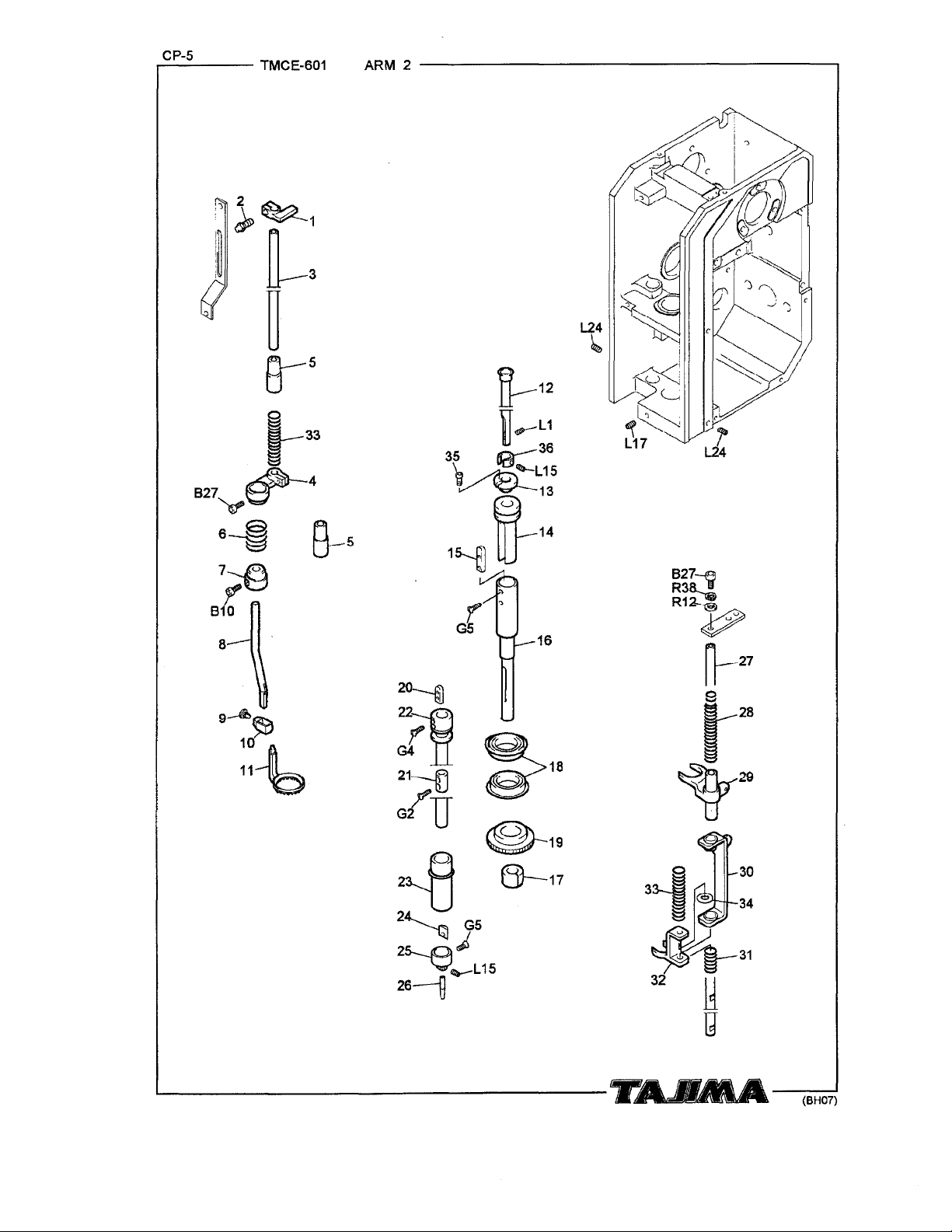
TMCE-601 ARM 2
-----------------,
11--12
L24
~
i
-~
lc
8
9~'$5?
10.-m
11
~
~Q::
L17
35
~
~~L1
re:-:36
~
lllilhL
15
v~::
1~UJ
16
827-e
R3~
R12-e
~
rl---27
~--~
~29
(BH07)
Page 13

TMCE-601 ARM 2
CP-5
Ref.No.
i
Presser
1
Presser
2
Presser
3
Presser
4
Presser
5
:presser
6
• Bracket Collar
7
Presser
8
Presser
9
Presser
10
Presser
11
Needle Bar
12
Needle Bar Tightening Collar
13
Needle Bar Lifting Sleeve
14
Needle Bar Reciprocating Sleeve
15
Needle Bar Sleeve
16
D-axis Gear Split Collar
17
Ball
18
D-axis Driven Gear
19
Reciprocating Sleeve
20
Nipple
21
Nipple
22
Sleeve
23
Nipple
24
Nipple Connecting Stud B
25
Nipple
26
Nipple
27
Needle Bar Spring
28
Needle Bar Slide Block
29
Nipple
30
Nipple
31
Nipple Lifting Block
32
Nipple
33
0-Ring
34
Needle Bar Collar Screw
35
36
Needle Position Gauge
37
38
39
40
41
42
43
44
45
46
47
48
i
49
I
50
Note:
As
Foot Lifting Block
Lifter Block Pin
Drive Shaft
Foot Bracket
Foot Bushing
Foot Return Spring
Bracket
Set
Screw
Connecting Stud
Foot B
Bearing
Reciprocating Sleeve Collar
Lifting Sleeve
Connecting Stud B
Drive
Shaft
Lifting Connenting Block
Reciprocating Block Spring
Presser
for parts with
Foot Spring
marks#
Description
Part
No.
CL0515000000
CL0516000000
CL0523000000
CL0524000000
CL0521000000
CE0226000000
CE0227000000
CL0519000000
CE0231000000
CE0230000000
CE0232BOOOOO
CL0502000000
CL0506000000
CL0505000000
Key
CL0508000000
CL0509000000
CL0541000000
BP6901ZNROOO
i
CL0540000000
Key
CE0219000000
CL0510100000
I
CL0510SOOOOO
CL0512000000
Spacer
CE0221000000
CE0220000000
CE0222000000
CL0522000000
CL0525000000
CL0514000000
CL0536SOOOOO
CL0527000000
CL0513000000
CL0526000000
EF0621000000
CL0507000000
CL0581000000
or*,
please follow our mstruchons on Table of Contents m your parts order.
Remark
(BH07)
Page 14

,....c_P_-6---
TMCE-601
X-AXIS
DRIVE SYSTEM
--------------,
812..._
R35.,_ i !=R35
R~9::
~
~_)F9
22~
810
s;~
; 88
!:R35
f R9
82~
L23~~1
./~
./
I-------------------~-~~---~
'--
10
11
-~......
7'
H29
(BH07)
Page 15

TMCE-601 X-AXIS DRIVE SYSTEM
Ref.
No.
Z-spec. Frame
1
Z-spec. Frame Felt
2
Z-spec. Frame
3
Z-spec. Frame
4
X-axis Pulse Motor i
5
X-axis Motor Plate A
6
Motor Cover
7
Spacer
8
X-axis Motor Plate B
9
Ball
10
11
12
13
14
15
16
17
18
19
20
21
22
23
24
25
26
Bearing
Z-spec. Frame Pulley A
Timing Belt
No.1
Pulley
Needle Bearing
Washer
U-shaped Bracket
X-axis Pin
E-ring
IT
ens
ion
Stay
IX-axis Traverse Linear
'Joint Plate
X-axis
Stack
X-axis Slit Plate
Belt
Presser
Z-spec. Frame Cover
Traverse Scale
27
28
29
30
31
32
33
34
35
36
37
38
39
40
41
42
43
44
45
46
47
48
49
50
Note:
As
for parts
With
Fixing
Fixing
Plate
Plate
marks#
Description
Block L
Block R
Way
or*,
please follow our mstructlons
on
Part
No.
ECOE01000000
EC0720000000
ECOE11LOOOOO
ECOE11ROOOOO
EC6401020000
ECOE16000000
ECOE22000000
ECOE21000000
ECOE23000000
BPR1980HHOOO
EC0709000000
BP015AT50299
CX0715000000
BPHK10100000
BPTW10200000
EC0704000000
EC0710000000
BPE700000000
EC0705000000
ECOL12000000
ECOE06000000
EC0707020000
EC0703000000
EC0702000000
ECOE03000000
CX07A3000000
I
Table
of
Contents m your parts order.
CP-6
Remark
:
I
j
(BH07)
Page 16

CP-7
,_:..:........;...._
__
TMCE-601
Y-AXIS DRIVE SYSTEM
23
~
~
B49
~22
~
----------------.
21
~
~-
B69 /
R42
·c;
I
R23
'
20
18
L23
(1/g
v 17
"'
!~
L23~~18
i.d19 L23
\fo~
L--.-
________
..-a
-~-~
._..,_a_____.
(BH07)
Page 17

Ref.
No.
Y-axis Frame L
1
Y-axis Frame R
2
Frame Bracket
3
Frame Bracket B
4
Y-axis Traverse Linear
5
Y-axis Belt Catcher
6
Y-axis
7
8
9
'Frame Cover A
10
11
12
13
14
15
16
17
IY-axis Collar
18
iBall
19
!Y-axis Pulse Motor Base
20
1
21
: Split Joint
22
'Y-axis Drive Shaft
23
24
Stack
Z
-spec.
Frame Stay L
Z-spec. Frame Stay R
Y-axis Tension Bearing
No.1
Pulley
Needle Bearing
Washer
Tension Shaft
Timing
Belt
Z-spec. Frame Pulley A
Bearing
Y-axis Pulse Motor
25
26
27
28
29
30
31
32
33
34
35
36
37
38
39
40
41
42
43
:
44
45
46
47
48
49
50
Note:
As
for parts wtth marks #
TMCE-601 Y-AXIS DRIVE SYSTEM
Plate
Description
Way
or
*, please follow our mstructtons on Table
I
i
Part
No.
ECOL02LOOOOO
ECOL02ROOOOO
EC0807000000
ECOM04000000
BPC2R0580267
CX0705000000
EC0708000000
CL0724LOOOOO
CL0724ROOOOO
CX07B7000000
CX07C5000000
CX0715000000
BPHK10100000
BPTW10200000
CX07C1000000
BP015AT5261Y
EC0709000000
ECOE25000000
BP6002ZZOOOO
ECOE14000000
EC6402000000
ECOE26000000
CLOA05000000
of
Contents m
your
parts order.
OP-7
Remark
-
--~~
~-
-
(BHO?)
--
Page 18

CP-8
TMCE-601 LOOPER·
ATH
F16
~40
v
f-aa
:>P37
TAIJAA_____,J
(BH07)
Page 19

TMCE-601
LOOPER·
ATH
CP-8
Ref.No.
Needle Plate A
1
Needle Plate B
1
I Needle Plate C
1
Looper Base Cover
2
Thread Holder, Upper
3
Thread Holding Spacer
4
Thread Holder Bracket
5
Looper
6
Looper Sleeve
7
Gear Stopper Base
8
Looper Thread Course
9
Spring Presser
10
Looper Case
11
Looper Case Positioning Plate
12
Looper Case Slide Unit
13
Thread Breakage
14
Case Fixing Lever
15
Lever Base Lid
16
Fixing Lever Base
17
Proximity Switch Base
18
Thread Breakage Detecting Switch
19
_Looper Base
20
i Pulse (Stepping)
21
1 A TH
Motor
22
1
Movable Knife Guide Plate
23
'Knife Drive Rack
24
iATH Sensor Plate
25
! Plate Presser Spring
26
1 A TH Drive Knife
27
1 A TH Knife Guide
28
, Looper
29
Pulse (Stepping)
30
1
Movable Knife Guide Holding
31
iATH Base
32
i Movable Knife Holding
33
i Thread Presser Spring
34
i Looper Spring
35
Ball Bearing
36
:Stopper Ring
37
Looper Base Stud
38
1 A TH Drive Gear
39
• Proximity Switch
40
-.Lever Pin
41
Thread
42
, Looper Drive Gear
43
;26P Split Collar
44
• Looper Drive Gear Bushing
45
1 A TH Fixed Knife
46
• Fixed Knife Guide
47
48
Note:
-
i Round Countersunk Head Screw
As
for parts with marks # or *, please follow our mstructmns on Table
Base
Motor
Guide
--
Description Part
PI
ate
Detecting
Motor
Base
Motor
Block
Switch
Block
Lever
CL0227000000
CL0228000000
CL0229000000
CL0230000000
CL0206000000
CL0207000000
CL0205000000
CL0231010000
CL0209000000
CL0203SOOOOO
CL0204000000
CL0232000000
CL0202010000
CL0241010000
CL0233010000
CL0243000000
CL0238SOOOOO
CL0237010000
CL0236010000
CL0242000000
CL0244000000
CL0201000000
CL0835010000
--·-
CL0215000000
CL0220000000
CL0217S20000
CL0222000000
CL0221000000
CL0226010000
CL0219000000
CL0211000000
CL0838020000
CL0234000000
CL0223010000
CL0225000000
CL0208000000
CL0210000000
BPLF1260ZZOO
BPWR60000000
CL0265000000
CL0216000000
EG6601000000
CL0240000000
FX0626110000
TT2010000000
CL0262000000
TT2009000000
CL0224020000
CL0235010000
EG0228000000
of
Contents m your parts order.
No.
Remark
1.6P
1.8P
1.4P
With Enooder
(BH07)
Page 20

CP-9
TMCE-601
TENSION BASE
A8
. V
2120~
15 16 17
\~~
~~
-\
14
13
1~~~
e~N
18
B~~
5
~
..
Page 21

TMCE-601 TENSION BASE
CP-9
Ref.No.
Tens
ion
1
Tens
2
Tens
3
Thread Tens
4
Tension Base Thread Guide
5
Color Change Bracket
6
Looper
7
Tension Base
8
Tension Collar
9
Looper Lower Lever
10
. Looper Lower Lever
11
Tension Release Pin
12
1 Adjusting Screw
13
1
Spring Hook
14
Tens
15
Tension Collar
16
'Felt Packing
17
Thread Course Tens
18
Insulation Plate
19
Thread Take-up Spring
20
Tens
21
Thread Course Thread Guide
22
Thread Course Tens
23
Release Plate Assembley
ion
Release Side Plate
ion
Release Slide Base
ion
Case
Slide Unit
ion
Spring
ion
Stud
24
25
26
27
28
29
30
31
32
33
34
35
36
37
38
39
40
41
42
i
43
44
45
46
47
48
49
50
Note.
As
for parts
With
marks#
Description
Fixing Block
Pin
ion
Disk
ion
Stud
or , please follow our mstructlons on Table
*
----
-
Part
No.
CL0408000000
CL0407000000
CL0455000000
CL0447000000
CL0401000000
CL0404000000
CL0233000000
CL0446000000
CL0435000000
CL0414010000
CL0415000000
LE0912000000
EF09090AOOOO
EF0910000000
EF0908000000
LG0959000000
EF0904000000
EF0913000000
EF0903000000
CL0434000000
CL0436000000
EF0912000000
EF0914000000
------
:
of
Contents m your parts order.
!
I
I
I
I
I
Remark
,_.
-------------
(BH07)
Page 22

1
0
_
,.....:C..:...P_-
--
TMCE-601
TENSION RELEASE
u
J
(_)
L15
l._~~'
17~
c.
834
~
1~~~~
L9
1~ c ~4
c
~
829
L--------------T~.MA
L15
('
' 12
~~!if::(
18
~Ut
(BH07)
Page 23

TMCE-601 TENSION RELEASE
CP-10
Ref.No.
Tens ion Release Lever Pin
1
Tens ion Release
2
Tens ion Release Return Spring
3
Tens ion Release Cam Tightening Collar
4
Z-axis Drive Gear
5
Tens ion Release Lever
6
Potentiometer
7
Pulse (Stepping)
8
Roller Pin 8
9
Potentiometer Stud B
10
Potentiometer Attaching Plate B
11
Tens ion Release Gear
12
Tens ion Release Drive Shaft
13
Thread Release Base 8
14
Tension Release 12P Collar
15
Thread Release Base A
16
Ball Bearing
17
Flanged
18
Tens ion Release Bracket
19
DU
Bushing
Description
Cam
Motor
20
21
22
23
24
25
26
27
28
29
30
31
32
33
34
35
36
37
38
'
<
39
40
41
42
43
44
45
46
47
48
49
50
Note: As for parts
With
marks#
or*,
please follow our mstructmns on Table
Part
No.
Remark
CL0411000000
CL0421000000
CL0416000000
CL0417000000
CL0543000000
CL0412000000
CL0842000000
:
CL0835010000
CE0117100000
CL0423000000
CL0422000000
CL0451000000
CL0453000000
I
CL0457BOOOOO
CL0452000000
CL0457AOOOOO
BP6901ZZOOOO
BPMB120620FD
CL0458000000
--
~
"·
\
\
I
-----
i
of
Contents m your parts order.
---
---/
/
I
!
I
I
---
--------
(BH07)
Page 24

CP-11
.........:-...:.....;__
__
TMCE-601 COLOR CHANGE SENSOR
------------,
1...---------lijjjiil-
-~
.....
--
(BH07)
Page 25

TMCE-601 COLOR CHANGE SENSOR
OP-11
Ref.No.
Color Change Sensor Gear
1
Color Change Sensor Rack
2
Flanged
3
Color Change Sensor Collar
4
i Color Change Potentiometer
5
I Potentiometer Stud
6
Potentiometer Attaching Plate
7
Color Change Sensor Base
8
Pin
9
Thrust Washer
10
11
DU
No.101
Bushing
12
13
14
15
16
17
18
19
20
21
22
23
24
25
'
26
27
28
29
30
31
32
33
34
35
36
37
38
39
40
41
42
43
44
45
46
47
48
49
50
Note:
As
for parts
With
marks#
Description
or*,
please follow our mstruct10ns on Table
No.
Part
CL0431000000
CL0450000000
BPMB060612FD
CL0430000000
CL0836000000
CL0428000000
CL0427000000
CL0449020000
CT0406000000
BPRTW0613000
'
-
--
of
Contents m your parts order. (BH07)
Remark
Page 26

CP-12
..-----
TMCE-601 THREAD STAND
-----------------.
L-----------iijpl-
R2~
R4'1--CII
P22-(9
.~
....
......
------~
(BH07)
Page 27

TMCE-601 THREAD STAND
CP-12
Ref.No.
Thread Stand Plate
1
Thread Course
2
Adjusting Screw
3
Tens
ion
4
Thread Course Tension Disk
5
Thread Course Tens
6
iThread Course Thread Guide
7
1
Thread Stand Stud
8
Thread Stand Shaft
9
;Thread Stand Felt
10
~Thread
11
!No.1
12
i Cushion Rubber
13
14
15
Spring
Stand Plate Attaching Bracket
Tension
Set
16
17
18
19
20
21
22
23
24
25
26
27
28
29
30
31
32
33
34
35
36
37
38
39
40
41
42
43
44
45
46
47
48
49
50
Note:
As
for parts
With
marks
Description
ion
Stud
#or
*, please follow our mstruct10ns on Table
Part
No.
CL0616010000
CL0617010000
EF09090AOOOO
EF0908000000
EF0913000000
EF0914000000
EF0912000000
EF0939010000
!
CT0603010000
EF0940000000
CT0604000000
UN150500B001
EC0829010000
of
Contents m your parts order.
.
....................
!
Remark
(BH07)
Page 28

CP-13
TMCE-601
BORDER
FRAME-----------------------------
Page 29

TMCE-601 BORDER FRAME
CP-13
Ref.No.
Border Frame
1
Border Felt
2
Border Frame L-plate
3
Frame Corner
4
Glued Corner
5
Border Frame
6
Border Frame
7
Border Frame
7
8
9
10
11
I
I
12
I
13
I
I
14
i
15
16
I
17
18
19
20
21
22
23
24
25
26
27
28
29
30
31
32
33
34
35
36
37
38
39
40
41
42
43
44
i
45
46
47
48
49
Note:
As
for parts wtth marks
-
Spacer
Spacer
Clip
Clip
#or
Description
Part
No.
CL0305000000
!
CX0386000000
CX0302010000
-
CX03C3000000
EC0201000000
EC0202000000
MX0320AO****
EF030700****
'
!
*,
please follow our mstruct10ns on Table of Contents m your parts order.
Remark
For Y-axis
For X-axis
---
(BH07)
Page 30

TMCE-601
ELECTRIC PARTS
32
33
-19
25
.844
~R40
®-R21
82~
17
R16.-.@
~
18
(BH07)
Page 31

TMCE-601 ELECTRIC PARTS
Ref.No. Description
Controller
1
FIP
2
3
4
5
6
7
8
9
10
11
12
13
14
15
16
17
18
19
20
21
22
23
24
25
26
27
28
29
30
31
32
33
34
35
36
37
38
39
40
41
42
43
44
45
46
47
48
49
50
Note. As for parts wtth
(Indicator Assembly)
CPU Card
• Switch Card
• Extension Card
I Floppy Disk Drive
FDD
Connector Conversion
Operation Panel Switch
Push-button
Push-botton
Circuit Protector
Terminal
Switch Guard
Breaker Lcok
Surge
Noise Filter
Joint
Joint Card
Power Supply Driver Unit
Electrical Component
DO
Power Supply
DO
Power Supply
DO
Power Supply
Card Bracket
Stud Bolt
X/Y-Axis Driver
Head Card
Fin
A
Fin
B
Fin
0
FinD
Card Support
Guide
Main
Shaft Driver
iFan Attaching
Stud Bolt
•Fan
I
I
i
I
i
I
I
Switch
Switch Emergency Stop Plate
Base
Protector
Card (PC Board)
Base
Rail
Base
marks#
or*,
Set
Sheet
Parts
Base
please follow our mstructtons on Table
No.
Part
EC5102A10000
PB000400LPOO
MX5101A40000
MX5102000000
CL5101060000
PBOOOBOOREOO
MX5104000000
EC5101000000
PB0019DOSPOO
PB0019COSPOO
PB002500KAOO
PB002600KAOO
CX08J1510000
I
CX08J1800000
PB001500RSOO
PBOOOBOOFMOO
MX6101000000
:
ECOF18000000
CL5605000000
ECOF06000000
EC5603000000
PB0025A1PWOO
PB002600PWOO
ECOF07000000
ECOF16000000
I
EC6102010000
CL6102000000
ECOF19000000
ECOF20000000
ECOF21000000
r
ECOF22000000
ECOF08000000
PB004100EBOO
CX5602070000
ECOF23000000
ECOF11000000
PB000900BFOO
of
Contents m your parts order. (BH07)
CP-14
Remark
Page 32

A·B
No.
A
Al
A2
A8
A4
A5
A6
A7
A8
A9
AlO
All
A12
AlB
A14
A15
A16
A17
AlB
A19
A20
A21
A22
A2H
A24
A25
A26
A27
B
Bl
B2
B3
B4
B5
B6
B7
BB
B9
BlO
Bll
B12
BlB
B14
B15
B16
Bl7
Bl8
Part
Flat
Fi
II
ister
SM15015450GN
I
SM15015455GN
SM15015460GN
SM16515530GN
SM14020540GN
SM16516540SA
SM17010540GN
SM1E515550CN
SM14020560GN
SM15525560GN
SM15526570GN
SM15020580GN
SM15530580CN
SM16025580GN
SM150205AOCN
SM150205COGN
SM150205FOGN
SM15422643TN
SM17017670GN
SM1G035675CN
SM10825690SH
SM146266B5CN
SM172316COCN
SS6003080SCO
SS6003080SOO
SS6003100CCO
SS6004100SCO
Hexagon
Socket
SS6202080TDO
SS6202100TDO
SS6276050TNO
SS6203030TNO
SS6203040TNO
SS6203050TNO
SS6203060TDO
SS6203060TNO
SS6203080TOO
SS6203080TNO
SS6203100TDO
SS6203100TNO
SS6203120TNO
SS6203150TDO
SS6203150TNO
SS6203160TNO
SS6203180TNO
SS6203200TDO
No.
Head
Head
M3XB
M3XB
M3X10
M4X10
Cap
M2X8
M2x10
M2.6X5
iM3
iM3
M3X5
M3X6
M3X6
M3X8
M3X8
M3X10
M3X10
M3X12
M3X15
M3X15
M3X16
M3X18
M3X20
Remark
Screw
1/BX44X5
1/BX44X5.5
1/8X44X6
9/64X40X3
9/64X40X4
0/64X40X4
9/64X40X4
9/64X40X5
9/64X40X6
9/64X40X6
9/64X40X7
9/64X40X8
9/64X40X8
9/64X40X8
9/64X40X10
9/64X40X12
9/64X4QX15
11/64X40X4.3
11/64X40X7
11/64X40X7.
1
1/6
4 X 4 0 X 9
1 1
/6
4 X 4 0 X 1
11/64X40X12
Screw
X 3
X 4
1.
No.
B19
B20
B21
B22
B23
B24
B25
B26
B27
B28
B29
BBO
B31
B32
BBB
B84
BB5
B36
...
B37
B38
5
B39
B40
5
B41
B42
B43
B44
B45
B46
B47
B48
B49;
B50
B51
B52'
B53
B54
B55
B56
B57:
B58.
B59!
B60
B61 I
B62
B63:
B64!
D65i
B66
B67
Hti8
Part
SS6203200TNO
SS6203250TNO
SS6204050TDO
SS6204050TNO
SS6204060TNO
SS6204080TOO
SS6204080TNO
SS6204100TDO
SS6204100TNO
SS6204120TDO
SS6204120TNO
SS6204150TNO
SS6204180TNO
SS6204200TOO
SS6204200TNO
SS6204250TNO
SS6204250TN1
SS6204300TNO
SS6204350TNO
SS6204400TNO
SS6204450TNO
SS6205060TNO
SS6205080TOO
SS6205080TNO
SS6'205100TOO
SS6205100TNO
SS6205100TPO
SS6205120TNO
SS6205140TNO
SS6205150TDO
1
SS6205150TNO
SS6205160TNO
SS6205180TNO
SS6205200TDO
SS6205200TNO
SS6205220TNO
SS6205230TNO
SS6205250TNO
SS6205300TNO
SS6205350TNO
SS6205350TN1
SS6205500TNO
I
SS6205500TN1
I
SS6205550TNO
SS6205600TNO
SS6205600TN1
SS6206080TNO
SS6206090TNO
SS6206100TNO
SS6206120TNO
No.
Re•ark
M3X20
M3X25
M4X5
M4X5
M4X6
M4X8
M4X8
M4x10
M4X10
M4X12
M4x12
M4X15
M4X18
M4X20
M4X20
M4X25
M4X25
M4X30
M4X35
M4X40
M4X45
M5X6
MSXS
M5X8
M5X10
M5X10
M5X10
M5X12
M5X14
M5X15
M5X15
M5X16
M5X18
M5X20
M5X20
M5X22
M5X23
M5x25
M5X30
M5X35
M5X35
M5X50
M5X50
M5X55
M5X60
M5X60
M6XS
M6X9
M6X10
M6X12
(BH07)
Page 33

B·C·D·E
No.
B
B69
B70
B71
B72
B73
B74
B75
B76
B77
87R
B79
BBO
881
B82
B83
B84
B85
B86
B87
B88
B89.
B90
B91
B92
B93
B94
B95
B96
B91
B.98
B99
BlOO
Part
Hexagon
Socket
SS6206150TNO
SS6206180TNO
SS6206200TNO
SS6206250TNO
SS6206300TNO
SS6206350TNO
SS6206400TNO
SS6206450TNO
SS6206450TN1
SS6206500TN1
SS6206650TNO
SS6506750TN1
SS6206800TN1
SS6206AOOTNO
SS6208120TNO
SS6208150TNO
SS6208150TPO
SS6208200TNO
SS6208250TNO
1
SS6208300TNO
SS6208350TNO
SS6208400TNO
SS6208400TN1
SS6208450TNO
SS6208450TN1
SS6208500TNO
SS6208600TNO
SS6208700TNO
SS6210250TNO
SS6210300TNO
SS6210400TNO
SS6212300TNO
No.
Head
!
Cap
Screw
M6X15
M6X18
M6X20
M6X25
M6X30
M6X35
M6X40
M6X45
M6x45
M6X50
M6x65
M6X75
Mexso
M6X100
M8X12
M8x15
M8X15
M8X20
M8x25
M8X30
M8x35
M8X40
M8x40
MBx45
1MB
X 4 5
IM8 X
1MB
X 6 0
M8x70
M10X25
M10X30
M10X40
M12x30
50
Re•ark
No.
Cl3
C14
Cl5
Cl6
Cl7
ClB
Cl9
C20
D
Dl
D2
D3
D4
D5
D6
D7
DB
D9
DlO
Dll
Dl2
Dl3
D14
Dl5
Dl6
Dl7
Dl8
Dl9
Part
SS9306750SCO
SS9308150TNO
SS9308180TNO
SS9310300TNO
SS9310350SCO
SS9310350TNO
SS9310400SC1
SS9312500TNO
Round
Fillister
SM66514540CL
I
I
SM66015550CL
:
SM66015550CN
SM67018550GN
:
SM67020550CN
SM66015560CL
SM66015560CN
SM67020560CL
SM67020560CN
SM65817568CN
SM67020580CN
SM660255AOCN
SM670205COCN
SM67015660CL
SM67010665CL
SM675306COCN
SM675256FOCN
SM69065CQ5CN
SS7003050SOO
No.
M6X75
.M8X15
'
M8Xl8
M10X30
M10X35
M10X35
M10X40
M12X50
I
I
Head
I
11/64X40X6
1 1
1 1
'1 1 ./6
:M3
Re111ark
Screw
9./64X40X4
9/64X40X5
9/64X40X5
9./64X40X5
9/64X40X5
9./64X40X6
9./64x40X6
9/64X40X6
9/64X40X6
9/64X40X6.8
9/64X40XB
9/64X40X10
9/64X40X12
/6
4 X 4 0 X 6 5
/6
4 X 4 0 X 1 2
4 X 4 0 X 1 5
9/3
2 X 2 8 X 2
X5
4.
--
5
c
Cl
C2
C3
C4
C5
C6
C7
CB
C9
ClO:
Cll
Cl2
Hexagon
Bolt
SS9303060SDO
SS9304080SDO
SS9305100SDO
SS9305150SCO
SS9305150SDO
SS9305200SDO
SS9306150SCO
SS9306450SDO
SS9306500SCO
SS9306500SDO
SS9306550SOO
SS9306650SDO
M3x6
M4x8
M5X10
M5X15
M5x15
M5X20
M6X15
M6X45
M6X50
M6X50
M6X55
M6x65
E
El
E2
E3
E4
E5
E6
E7
EB
E9
ElO
Ell
El2
Pan
Head
SS41640
SS4102030MZO
SS4102040MZO
SS4102080MZO
SS4175030MZO
SS4175040MZO
SS4175050MZO
SS4175080MZO
SS4175130MZO
SS4175130SDO
SS4103030MZO
SS4103030SDO
Screw
14MZO
M1.4X1.4
M2X3
M2X4
M2X8
M2.5X3
M2.5X4
M2.5X5
M2.
5 X 8
M2.5X13
M2.5X13
M3X3
M3X3
(I3H07)
Page 34

No.
E
E13
E14
E15
Ele
E17
ElBI
E19
E20
E21
E22
E23
E24
E25
E26f
E.'27
E28!
E29
E30
E81!
E32:
E33!
E34
F-35
E36
E37
EBB
E39
E40
E41
E42
E43
E44
E45
E46
E."47
E48
E49
E50
E51
E52
E53
E54
Part
Pan Head
SS4103040GOO
SS4103040MZO
SS4103040SDO
SS4103050MZO
SS4103050SDO
SS4103060MZO
SS4103060SAO
SS4103060SDO
SS4103080MZO
SS4103080SAO
SS4103080SDO
SS4103100SC1
SS4103100SDO
SS4103120MZO
i
SS4103120SDO
SS4103140SAO
i
SS4103140SDO
1
SS4103150SDO
SS4103400SD1
SS4103500SD1
SS4104040SDO
I
SS4104050SDO
SS4104060MZO
SS4104060SDO
SS4104080SDO
SS4104100SDO
SS4104120SDO
SS41
04150800
SS4104180SDO
SS41
04500SDO
SS4104600SD1
SS4105060SDO
SS4105070SDO
SS4105080SDO
SS4105100MZO
SS4105100SDO
SS4105120SDO
SS4105300S01
SS4105150SOO
SS4105450SD1
SS4105500SD1
SS4105600SD1
No.
Sorew
·----··-··
I
M3X4
M3X4
M3X4
M3X5
:Ma
x5
1M3
X 6
M3X6
M3X6
M3XS
M3x8
M3X8
M3X10
M3X10
M3X12
M3x12
M3X14
M3X14
M3X15
M3X40
M3X50
M4X4
M4X5
M4X6
M4X6
M4X8
M4x10
M4X12
M4X15
M4X18
M4X50
M4x60
M5X6
M5X7
M5X8
M5X10
M5X10
M5X12
M5X12
M5x15
M5X45
M5X50
M5X60
Reraark
No.
F4
.............
F5
F6
F7
FB
F9
FlO
Fll
F12
F18
F14
F15
F16
F17
FIB
Fl9
F20
F21
F22
F28
F24
F25
F26
F27
F28
F29
F30.
F31
F32'
F:J:J
F34
F35
F:J6
F37
F38
F39
F40
F41
F42
F43
F44
Part
SS1103040MZO
SS1103040SDO
SS1103050SDO
SS1003060SDO
SS1103060MZO
SS1103060SDO
SS1103070SDO
SS1003080SDO
SS1103080MZO
SS1103080SCO
SS1103080SDO
SS1103080SNO
SS1103100SDO
SS1103120MZO
SS1103120SDO
SS1103150MZO
SS1103160SDO
SS1104050SDO
SS1104060SDO
SS1104080MZO
SS1104080SDO
SS1104100MZO
SS11
041
SS1104120SDO
SS1104140SDO
SS1104150SDO
SS1104200SDO
SS1104220SDO
SS1104250SDO
SS1105060SDO
I
SS1105080SDO
SS1105100SDO
SS1105120SDO
SS1105150SDO
SS1105300SDO
SS1105350SDO
SS1106150SCO
SS1106150SDO
SS1106350SDO
SS1108120SDO
SS1108700TNO
No.
··-·
OOSDO
E·F·G
Re•ark
M3X4
M3X4
M3x5
M3X6
iM3
X6
1
M3
X 6
M3X7
M3xS
M3X8
M3XS
M3X8
M3X8
M3X10
M3X12
M3X12
M3X15
M3X16
M4X5
M4X6
M4X8
M4X8
M4X10
M4X10
M4X12
M4X14
M4X15
M4X20
M4X22
M4X25
M6X6
M5X8
M5X10
M5XI2
M5X15
M5X30
M5X35
M6X15
M6X15
M6X35
M8X12
M8X70
Countersunk
F
Fl
F2
F3
SMA55005AOGN
SMB7000680CN
SS1102060SDO
Head
Screw
i9/64X40X10
11/64x4oxa
1M2 x 6
G
Gl
G2
Gil
Round
Countersunk
SMG5000460GL
SMG5000530GL
SMC5000535GL
Head
Sorew
1/8X44X6
9/64X40X3
9/64X4QX3.5
(BH07)
Page 35

No.
G
G4
Go
G6
G7,
lliTruss
Hl
H2;
H3
H4
H5
H6
HI
HB
i
H9
HlO
Hll
Hl2•
Hl3
Hl4
Hl5!
Hl6
H17
Hl8
Hl9i
H2o;
1
H21
H22
H23
H24
H25
H26
H27
H28'
H29
i
H30
H31
H32
H33
H34
H35
H36
H37
H38
H39
Part
Round
Countersunk
SMC5000540CL
SMC5000560CL
SMC5000570CL
SMC5000595CL
Head
SMF6016470CL
SMF8020530CL
SMF8020540CL
SME9510540CM
SMF8020560CL
SMF8020680CL
SS0175030MZO
SS0175030SDO
SS0175040MZO
SS0175040SAO
SS0175040SDO
SS0103030MZO
SS0103030SDO
SS0103040SDO
SS0103050MZO
SS0103050SDO
SS0103060MZO
---
SS0103060SDO
SS0103060SAO
SS0103080SOO
SS0103080SAO
SS0103100MZO
SS0103100SDO
SS0103200SDO
SS0104050SDO
SS0104060MZO
SS0104060SDO
SS0104080MZO
SS0104080SDO
SS0104080SD2
SS0104100MZO
SS0104100SDO
SS0104120SDO
SS0104150SDO
SS0104200SDO
SS0105050SDO
SS0105060SDO
SS0105065SDO
SS0105070SDO
No.
Screw
Head
Screw
9/64X40X4
9/64X40X6
9/64X40X7
9/64X40x9.5
1/8X44X7
9/64X40X3.5
9/64X40X4
9/64X40X4
9/64X40X6
9/64X40X8
M2.
5 X 3
M2.5X3
M2.
5 X 4
M2.5X4
M2.
5 X 4
M3X3
M3X3
M3X4
M3X5
M3X5
M3X6
M3X6
M3X6
M3X8
M3X8
M3X10
M3X10
M3X20
M4x5
M4X6
M4X6
M4XB
M4X8
M4x8
M4X10
M4x10
M4x12
M4x15
M4X20
M5X5
M5X6
M5x6.5
M5X7
Re•ark
No.
H40
H41
-·
H42
H4/J
H44
H45
H46
H47
H48
H4.9
H50
H51
H52
J
]1
]2
j:J
]4
K
Kl
K2
K3
K4
K5
K6
K7
KB
K9
K10
Kll
Kl2
K1S
Kl4
Kl5
Kl6
K17
Part
No.
SS0105080SDO
SS0105100CBO
SSO 1 051
OOSDO
SS0105120SOO
SS0105150SOO
SS0105200SOO
SS0105250SOO
SS0106080SOO
SS0106100SOO
SS0106220SOO
SS0106250SOO
SS0106350SOO
SS0106400SOO
Round
Head
Screw
SS3102030MZO
SS3103080SOO
SS3103080SEO
SS3103100MZO
Slotted
Set
Screw
SMK0000435CN
SMK0000560CN
SMK0000625CN
SMK0000635CN
SMK0000640CN
SMK0000650CN
SMKOOOOA50CN
SMKOOOOAAOCN
SMKOOOOAFOCN
SMKOOOOAHOCN
SMKOOOOB40CN
SMKOOOOB45CN
SMKOOOOB50CN
SMKOOOOB60CN
SMKOOOOB80CN
SMKOOOOCGOGN
SS8005060TNO
I
I
M5X8
M5X10
-
M5X10
M5X12
M5X15
M5X20
M5X25
M6X8
M6X10
M6X22
M6X25
M6X35
M6X40
M2X3
M3X8
M3XS
M3X10
1/8x44X3.5
9/64X4QX6
11/64X40X2.5
11/64X40X3.5
11/64X40X4
11/64X40X5
15/64X28X5
15/64X28X10
15/64X28X15
15/64X28X17
1/4X40X4
1/4X40X4.5
1/4x40X5
1/4X40X6
1/4X40X8
9/32X28X12
M5X6
Re•ark
--
~
(BH07)
Page 36

No.
L
L1
L2
L3
L4
L5
L6
L1
L8
L9
LlO
Lll
L12
L13
L14
L15
L16
L17
LlB
L19
L20
L21
L22
L23
L24
L25'
L26
L211
L28
L29
LBO
L31
L32
L33
L34
L35
L36
M
Ml
M2
M3
M4
N
Nl
N2
Part
Hexagon
Socket
SMJ0000425CN
SMJ0000690CN
SMJ0000640CN
SMJ0000660CN
SMJ0000680CN
SMJOOOOA40CN
SMJOOOOA90CN
SS8203020TNO
SS8203030TNO
SS8203040TNO
SS8203050TNO
SS8203060TNO
SS8203080TNO
SS8204030TNO
SS8204040TNO
SS8204050TNO
SS8204060TNO
SS8204060TN1
SS8204080TNO
SS8204100TNO
SS8204120TNO
SS8205040TNO
SS8205050TNO
SS8205060TNO
SS8205080TNO
SS8205100TNO
SS8205120TNO
SS8205150TNO
SS8206050TNO
SS8206060TNO
SS8206080TNO
SS8206100TNO
SS8206180TNO
SS8208080TNO
SS8208100TNO
SS8208150TNO
Hexagon
Socket
SS3203050SCO
SS3204060SCO
SS3205100SCO
SS3205100SDO
Screw
with
SSA003080000
SSA003180000
No.
Head
Head
Washer
Re•ark
Set
Screw
1/8X44X2.5
11/64X28X9
11/64X40X4
, 1 1
/6
4 X 4 0 X 6
'1 1 /6
'15/64X28X4
!15/64X28X9
M6X8
M6X10
M6X18
M8X8
M8X10
M8X15
Button
M3X5
iM4
1
M5
1M5 X 1 0
M3X8
M3X18
4 X 4 0 X 8
M3X2
M3X3
M3X4
M3X5
M3X6
M3xs
M4X3
M4x4
M4X5
M4X6
M4X6
M4xs
M4X10
M4x12
M5X4
M5X5
M5X6
M5X8
M5X10
M5X12
M5X15
M6X5
M6X6
Screw
X6
X 1 0
No.
N3
N4
N5
N6
NT
N8
N9
p
Pl
P2
P3
P4
P5
P6
P1
P8
pg
PlO
Pll
P12
P13
P14
P15
P16
P17
PJB
P19
P20
P21
P22
P23
P24
P25
P26
P27
P28
P29
P30
P31
P32:
P33
P84
P35
P36
P31
Part
SSA004080000
SSA004100000
SSA004550000
SSA005100000
SSA005120000
SSA005140000
SSA005180000
Nut
I
SMN046030CNO
I
SMN056030CNO
I
I
SMN066020CNO
I
SH66030CNO
SMN067030CNO
SMN167030CNO
SSN002SDOOOO
SSN073SDOOOO
SSN075MZOOOO
SSN003MZOOOO
SSN003SCOOOO
SSN003SOOOOO
SSN403SDOOOO
SSN203SCOOOO
SSN203SDOOOO
SSN285SCOOOO
SSN004SCOOOO
SSN004SDOOOO
SSN204SCOOOO
SSN204SDOOOO
SSN005SCOOOO
SSN005SDOOOO
SSN205SCOOOO
SSN205SDOOOO
SSN605SDOOOO
SSN006SCOOOO
SSN006SC1000
SSN006SOOOOO
SSN006SD1000
SSN206SCOOOO
SSN008SCOOOO
SSN008SOOOOO
SSN208SCOOOO
SSN208SDOOOO
SSN010SCOOOO
SSN710CDOOOO
SSN710SCOOOO
No.
Re•ark
M4X8
1M4 X 1 0
IM
4 X
55
M5X10
M5X12
M5X14
M5X18
1/SX44X6X3
9/64X40X6X3
1 1
/6
4 X 4 0 X 6 X 2
1 1
/6
4 X 4 0 X 6 X 3
11/64X40X7X3
1 1
/6
4 X 4 0 X 7 X 3
M2
M2.
M2.
M3
M3
M3
M3
M3
M3
M3.
M4
M4
M4
M4
M5
M5
M5
!M5
M5
M6
M6
M6
M6
M6
MS
MS Type 1
MS
MS
M10
M10
M10
Type
Type
3
Type
5
Type
Type
Type
Thumbscrew Type 2
Type 3
Type 3
5 Type 3
Type
Type
Type 3
Type 3
Type
Type
Type 3
Type 3
Gap
Type
Type
Type
Type 1
Type
Type
Type 3
Type 3
Type
with
with
1
1
1
1
1
1
1
1
1
1
Screw
1
1
1
3
1
1
Flange
Flange
(BH07)
(Left)
(Left)
Page 37

No.
p
P38
P39
P40
P41
R
Rl
R2
R8
R4
R5
R6
RT
RB
R9
RJO
Rll
R12
R13
R14
R15
R16
R17
R18
R19
R20
R21
R22
R23
R24
R25
R26
R2T
R28
R29'
R30
R31
R32
R33
R34
R35
R36
R3T
R38
R39
R40
P·R
Part
!
Nut
SSN012SCOOOO
SSN212SCOOOO
SSN216SCOOOO
SSN020SCOOOO
Washer
WSP640303MZO
WSP023505XZO
WSP767505XBO
WSP036003XZO
WSP036005SCO
WSP037005SDO
WSP038003SDO
WSP038005MZO
WSP038005SCO
WSP038005SDO
WSP038100SDO
1
WSP048005SCO
WSP048005SDO
WSP048008SCO
WSP048008SDO
WSP04A008SCO
WSP04A008SDO
WSP04C010SCO
ISP05A008SCO
ISP05A008SDO
WSP05C008SCO
WSP05C008SDO
ISP06D010SCO
WSP060010SDO
WSP06G010SCO
WSP08G012SDO
WSP08J016SCO
WSP08J016SDO
WSP08J032SCO
·
WSP08N032SCO
WSP10S032SCO
WSP12L520SCO
WSS020000KDO
WSS760000KCO
WSS030000KCO
WSS030000KDO
WSS850000KCO
WSS040000KCO
WSS040000KDO
WSS050000KCO
No.
M12
M12
:M
1 6
IM20
I
-
Plain
Plain
Plain
Pl•in
Plain
Plain
Plain
Plain
Plain
Plain
Plain
Plain
!Plain
Plain
Plain
Plain
Plain
Plain
Plain
Plain
Plain
Plain
Plain
Plain
Plain
Plain
Plain
Plain
Plain
Plain
Plain
Plain
1Spr i ng
!Spring
ispr ing
Spring
Spring
Spring
Spring
Spring
Re111ark
Type
1
Type
3
Type
3
Type
1
M1.4X3X0.3t
M2X3.5X0.5t
M2.
6X7.
M3X6X0.3t
M3X6X0.5t
M3X7X0.5t
M3X8X0.3t
M3X8X0.5t
M3X8X0.5t
M3X8X0.5t
M3X8X1
M4X8X0.5t
M4X8X0.5t
M4X8X0.8t
M4X8X0.8t
M4X10X0.8t
M4X10XO.St
M4X12X1
M5X10X0.8t
M5X10X0.8t
M5X12X0.8t
M5X12X0.8t
M6x13X1.0t
M6x13x1.0t
M6x16X1.0t
M8X16X1.2t
M8X18X1.6t
M8X18X1.6t
M8X18X3.2t
M8X22X3.2t
M10X26X3.2t
M12X20.5X2t
M2
M2.
6
M3
M3
M3.
5
M4
M4
M5
5X0.
t
Part
No.
:
R41
R42
R43
R44
R45
R46
R47
R48
R49
R50
R51
R52
5 t
R53
t
WSS050000KDO
WSS060000KCO
WSS060000KDO
WSS080000KCO
WSS080000KDO
WSS100000KCO
WSS120000KCO
WSW06B003TPO
WSW06A503TNO
WSL048505TPO
WSL05A006TPO
WSNOSOOOOSCO
WSC048005SCO
No.
Spring
Spring
Spr ing
1
'Spring
Spring
Spring
Spring
Wave
M4
Wave
M6
With
teeth
With
teeth
Slant
MS
Disk Spring
'
Re~aark
M6
M6
M6
MS
MS
M10
M12
M4
M5
M4
(BH07)
 Loading...