

Page 1

O-RM01-E
(9911)
USIR'S
MANUAL
PARTS
,
LAME
ATTACHMIN1
LIST
/J/J/J
TA.JINlA
[Y[Y[Y
Page 2

FOREWORD
FOREWORD
This User's Manual and Parts List describes the using and setting methods for the lame
attachment.
Please read through this manual
setting the attachment.
of
The contents
[IMPORTANT SAFETY INSTRUCTIONS]
[SETTING
[EMBROIDERY USING LAME FILM]
[PARTS LIST]
Always keep this manual at hand whenever you need.
If
you do not use the lame attachment, keep this manual for future use.
This manual may contain discrepancies in detailed information when compared with actual
product
ued research and improvements
If
TAJIMA
due
any question about the unit
distributor.
this manual are largely divided into the following sections.
THE LAME ATTACHMENT]
to differences
carefully and understand the contents before operating
in
machine models for which the product is used and also contin-
of
the product.
or
contents
of
this manual arises, please consult your local
or
(CG11)
Page 3
IMPORT ANT
SAFETY
INSTRUCTIONS
IMPORTANT
Correct work is required for safe handling (using and setting)
Please read the IMPORTANT SAFETY INSTRUCTIONS
carefully
items written under
which require your special attention on the using
Items
specified
to ensure safety during using and setting the attachment.
Signal word definition is given below.
Indicates a potentially hazardous situation which,
or
moderate injury (*1) or property damage.
*1:
{S)
SAFETY
and do not attempt operation
following the warning symbol and signal word. These items must be strictly observed
INSTRUCTIONS
in
of
the machine before you thoroughly understand the
IMPORTANT SAFETY INSTRUCTIONS.
and
of
the lame attachment.
this instruction manual and parts list
setting
of
the lame attachment are
A CAUTION
if
not avoided, may result in minor
An
injury that does not necessitate hospitalization or visit
Prohibited
items
to
a hospital over a
long
period.
0 : Items
The information which gives
NOTE.
that
must
details
be
followed
carefully
or
supplements the explanation appears under the title
to
ensure safe operation.
A CAUTION
Before carrying
power switch OFF.
If
you attempt an operation with the power switch ON, the machine could
operate unexpectedly and
out
operation described in this manual, make sure turn the o
could cause injuries.
A CAUTION
Oily chips
When cleaning the ATH device, make sure to completely remove lame film
chips.
Thread
of
lame film may adhere
will not
be
trimmed correctly
to
the ATH knife
if
lame film chips remain on the ATH knife.
or
the rotary hook. o
ii
(CG11)
Page 4

CONTENTS
CONTENTS
• FOREWORD ................................................................................................................................................ i
• IMPORTANT SAFETY INSTRUCTIONS ....................................................................................................
• SETIING
1.
2.
"ll
t.l.
THE
LAME ATIACHMENT ....................................................................................................... 1
FUNCTIONS
OF
LAME ATIACHMENT ........................................................................................... 1
PARTS ............................................................................................................................................... 1
ILI~"T"AI
11'1\:> I 1"\L.LII'I"-.:'
I
1._11"'
TU~
Inc
I
Al.tr=
1\.TTAr"-UI.aL~IT
LI"\IVIt;:.
/"'\I
I
1"'\VniVI~I't
I
······································•••·········••·•·•••·•••·••••·····••••••···••••••••-.
3-1. Attaching the Positioning Thread Plate ................................................................................... 2
3-2. Attaching the Tension Release Set.. ....................................................................................... 3
· Attaching the Tension Release Set A ..................................................................................... 3
4.
SETIING LAME FILM ....................................................................................................................... 5
5.
ADJUSTING LAME FILM TENSION ................................................................................................. 7
&
EiviBROIDERY
1.
DESIGN DATA .................................................................................................................................. 8
· Attaching the Tension Release Sets
3-3.
Attaching the Roller-type Middle Thread Guide Set ................................................................ 4
4-1. Tension Release
4-2. Tension Release
USING
SetA
Sets
LAiviE
............................................................................................................ 6
C, D and
FILrvi
.......................................................................................................... 8
C,
D and E .................................................................... 4
E ........................................................................................... 7
ii
.,
2.
LAME
FILM
AND 3-D EMBROIDERY ............................................................................................... 8
• PARTS LIST .........................................................................................................................
End
of Volume
iii
(CG11)
Page 5
II
NOTICE FOR CHANGE OF CONTENTS
IN
USER'S MANUAL (2000.01) I
We have improved the middle thread guide
embroidery, threfore it is now not neccessary to use special middle thread guide, etc., for exclusive use. Following the above-mentioned improvement,
of
tents
lame embroidery.
tt
the user's manual as shown below. Please also refer to this notice when you execute
Page
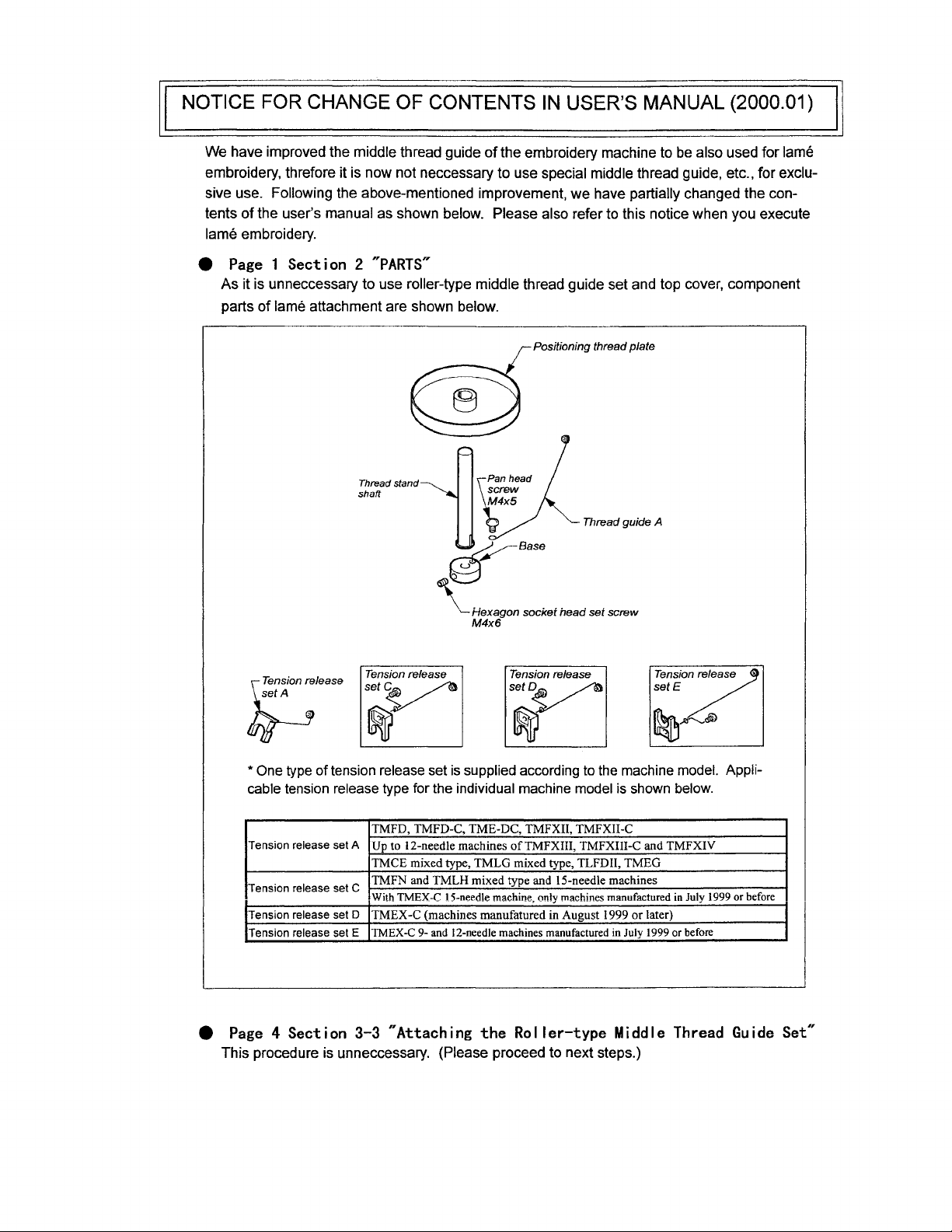
1 Section 2
As
it is unneccessary to use roller-type middle thread guide set and top cover, component
parts
of
lame attachment are shown below.
~PARTS~
Thread stand
shaft
of
the embroidery machine to be also used for lame
we
have partially changed the con-
Positioning thread plate
Thread guide A
~Base
\~:7~on
:lease
Tension release
set~
\_Hexagon
M4x6
socket head set screw
Tension release
y
~
*One
type of tension release set
cable tension release type for the individual machine model
Tension release
Tension release
Tension release
Tension release
4t
Page
4 Section 3-3
This procedure is unneccessary. (Please proceed to next steps.)
~
is
supplied according to
TMFD, TMFD-C,
set
A
Up
to 12-needle machines
TMCE mixed type,
TMFN and TMLH mixed type and 15-needle machines
set
C
With
TMEX-C
set
D
TMEX-C
set E TMEX-C
9- and
~Attaching
TME-DC,
TMLG
!5-need!e machine, only machines manufactured
(machines manufatured in August 1999
12-need1e
TMFXII, TMFXII-C
ofTMFXIII,
mixed type, TLFDII,
machines manufactured
the
Roller-type
TMFXIII-C and
Tension release
setE
the
machine model. Appli-
is
shown
below.
TMFXIV
TMEG
in
July 1999 or
or
later)
in
July
1999
or before
Middle Thread
before
Guide
Set"
Page 6

SETTING THE LAME ATTACHMENT
SETTING THE LAME ATTACHMENT
1.
2.
FUNCTIONS
A lame attachment is designed to perform embroidery using lame film.
OF
LAME
ATTACHMENT
PARTS
Component parts
Thread
stand
of
a lame attachment are shown below.
shaft
Thread
guide A
~Base
~Hexagon
W.4x6
socket
head
set
screw
Top
cover
•
This
cover
machines
and after July
is
necessary for
manufactured in
of
1999.
Tension
~!t"~ion
~lease
release
y
~
One
type
of
*
Applicable tension release type for the individual machine models is
shown
Tension release set A
Tension release set
Tension release set D
Tension release set E
tension release
below.
C
TMFD, TMFD-C, TME-DC, TMFX
Up
to 12-needle machines
TMFXIV
TMCE mixed type, TMLG mixed type,TLFD
TMFN and TMLH mixed type and 15-needle machines
With TMEX-C 15-needle machine, only
manufactured before July
TMEX-C (machines manufactured after August
TMEX-C 9- and 12-needle machines manufactured before
of
July
Tension
release
y
set
is supplied according
1999
Tension
setE~
~
to
the machine model.
IT,
TMFX II-C
of
TMFX III, TMFX
of
1999
relea/
II,
TMEG
machines
of
III-C
1999)
and
(CG11)
Page 7

SETTING THE LAME ATTACHMENT
3.
INSTALLING THE LAME ATTACHMENT
A CAUTION
Do not ride on the table when installing the lame attachment. Otherwise, the table
may be bent.
If
you must ride on the table to perform the necessary work, mount the table sup-
port.
3-1. Attaching the Positioning Thread Plate
1. Attach the thread guide A (1) to the base (2) using pan head screw M4 x 5 (3).
1
~2
2.
Set the base (2) on the thread stand stud (4)
ening the set screw (5) with the base (2) positioned
·
of
the thread stand plate and fix the base (2) by tight-
at
the lower end position.
NOTE:
Attach the base (2) in the direction
with the adjacent thread cone. For
the rear right direction as shown
below.
2
so
that the thread guide A (1) will
example, the thread guide A (1) should
not
interfere
be
set in
(CG11)
Page 8

SETTING THE LAME ATTACHMENT
3. After inserting the positioning thread plate (7) into the thread stand shaft
thread stand stud
(4).
t
76~~
u
4
3-2. Attaching the Tension Release Set
The procedure
type.
for
attaching the tension release set differs depending
(6),
set them
on
the tension release set
on
the
e
Tension
e Tension release sets
3-2-1. Attaching the Tension Release Set A
Fit the tension release set A (1) to the neck
release
set
A ........................................................ : ..........
C,
D and
E:
................................................. p.4
p.3
of
the No. 1 tension on the individual tension base.
3
(CG11)
Page 9

SETTING
THE
LAME ATTACHMENT
3-2-2. Attaching the Tension Release Sets
Fit the thread release set
thread stand section.
C,
D or E (2) to the thread guide (3) right above the corresponding
e Thread release set C and D
C, D and
E
e Thread release set E
3-3. Attaching the Roller-type Middle Thread Guide Set
NOTE: The machines shipped before June
Therefore, change
the procedure described below.
1.
Remove the attaching screws (1).
2. After removing the attaching screws (2), detach the top cover (3).
3
only the middle thread guide for these machines by referring
of
1999 have a removable middle thread guide.
4
(CG11)
Page 10

SETTING THE LAME ATTACHMENT
3. Attach the lame attachment top cover (4) using the attaching screws (2) and attach the roller-type
middle thread guide set (5) to it using the attaching screws
NOTE: Use the attaching screws
5
(1)
and
(1
).
(2)
removed in steps 1 and
2.
4.
SETTING LAME FILM
The procedure for setting lame film differs depending on the tension release set type.
e Tension release
e Tension release sets
NOTE: Pay attention
* Unwind lame
* When threading lame film through the needle eye, pull the film gently between
setA
................................................................... p.6
C,
D and
E:
................................................. p.7
to
the
following points when unwinding lame film.
film
gently.
plate
will
turn excessively causing the film
tioning thread plate
the thread guide and the individual thread guide and, also,
film is pulled only
threading difficult.
at
If
the film is pulled forcibly, the positioning thread
turns
excessively,
the needle, the film
stop
will
to
be
it
by hand.
be
unwound
stretched
too
much.
at
the needle.
to
be
cut
or
If
the posi-
If
the
making
5
(CG11)
Page 11

SETTING THE LAME ATTACHMENT
4-1. Tension Release Set A
Set lame film
in
the manner as shown below.
Threading hereafter can
made in the same manner
as ordinary thread.
be
6
(CG11)
Page 12

SETTING THE LAME ATTACHMENT
4-2. Tension Release Sets
Set lame film in the manner as shown below.
Threading hereafter can
made in the same manner
as ordinary thread.
C,
0 and E
be
t----Lame
film
5.
ADJUSTING LAME FILM TENSION
Check the lame film tension by pulling the film
eye so that the positioning thread plate turns slowly.
than the force needed for rayon yarn), the tension is correct.
For the under thread, adjust the tension a little higher than the tension set for rayon yarn.
in
the state the film is threaded through the needle
If the pulling force is 150 g (a little higher
7
(CG11)
Page 13

EMBROIDERY USING LAME FILM
EMBROIDERY USING LAME FILM
1.
2.
DESIGN DATA
Lame film is
and tatami stitch and embroidery with too short stitch
broken by a
high-quality goods, prepare the design that meets the following requirements.
e There are no overlap stitching
e Thread density
e The design does not contain stitches smaller than 0.6
0.1
to 0.3 mm wide. Overlap stitching on lame film, dense stitching like satin stitch
length may cause sewn lame film to be
needle or get fluffy.
in
satin or tatami stitching should
To
perform beautiful embroidery with lame film and produce
on
lame film.
be
0.5
mm
or more.
mm.
e There are no fray preventive stitches before thread trimming.
*1: Fray preventive stitches often cause
automatically processes fray preventive stitching, use the design data that does not include
such stitches.
LAME
3-D embroidery frequently generates satin stitches with thread density
lame film
film should
FILM
AND
tends
to
be broken
not be used for
3-D EMBROIDERY
or
gets fluffy due to a sticking needle
3-0
embroidery.
lame film to
be
broken or get fluffy. Since the machine
of
about 0.2 mm. Since
if
thread density is tight, lame
8
(CG11)
Page 14

•
LAME
PARTS LIST
ATTACHMENT
CONTENTS
............................................
RM-1
[Explanation of Marks #'s and
+ Please specify,
and embroidery space when you order us with the parts having
the part No.:
Ex.: TME-DC915 (450 x
[Model]
in
the following manner, your machine model, manufacturing number
[Emb. Space]
460)S
*'s
at End of Part No.]
01234
NO.
[Mfg. No.]
+ Please specify the number of needles on your machine's head
changing the
Ex.: The part Number, EK012345####
marks####
4-digit Numbers
into one of the 4-digit numbers below:
Machine Type
0300
0600
0900
1200
1500
........
........
........
........
........
3-nesdle machine
6-needle machine
9-needle machine
12-needle machine
15-needle machine
****
in
your parts order by
at the end of
(CG11)
Page 15

1
~R_M_-_
____
~MEATTACHMENT------------------------------------l
11
12
13
~
~
~~io---
~
~
~~
~
1
14~
~13
(COil)
Page 16

LAME
No.
1
Positioning Thread Plate
2 Thread Stand Shaft
3 Base
4
Hexagon Socket Head Set Screw
5
Thread Guide A
Pan Head Screw
6
Tension Release Set A
7
Tension Release Set C
8
Spring Hook A
9
Tension Release Spring 8
10
Pan Head Screw
11
12
Tension Release Set D
13
Spring Hook 8
14
Tension Release Set E
15
Tension Release Spring A
16
Top Cover
16
Top Cover
17 Roller-type Middle Thread Guide Set
18
Thread Guide
19
Round Countersunk Head Screw
20
21
22
23
24
25
26
27
28
29
30
31
32
33
34
35
36
37
38
39
40
41
42
43
44
45
46
47
48
49
NOTE:
As
for
parts with marks #
Name
or
•,
please follow
ATTACHMENT
No.
Part
RM0101100000
RM0101200000
RM0101300000
SS8204060TNO
RM0101400000
SS4104050SDO
RM0102SOOOOO
RM0107COOOOO
RM0105AOOOOO
RM0106BOOOOO
SS4103050SDO
RM0107DOOOOO
RM0105BOOOOO
RM0107EOOOOO
RM0106AOOOOO
CX067100##f#
CXC67100####
RM0104SO###f
FX0626110000
SM:5000535CL
our
instruction
on
Table
of
Contents, in
Remark
M4X6
M4X5
For the applicable models, refer
For the applicable models, refer
M3X5
For the applicable models, refer
For the applicable models, refer
For Jumbo rotary hook
9/64X40X3.5
your
parts order.
RM-1
to
2.
to
2.
to
2.
to
2.
(CGll)
"Parts".
"Parts".
"Parts".
"Parts".
 Loading...