


N930R
User Guide
English

Copyright©2005
All Rights Reserved - Printed in Taiwan
Notebook Computer User Guide
Original Issue: 2005/8
This manual guides you in setting up and using your new notebook computer. Information in
this manual has been carefully checked for accuracy and is subject to change without notice.
No part of this manual may be reproduced, stored in a retrieval system, or transmitted, in any
form or by any means, electronic, mechanical, photocopy, recording, or otherwise, without
prior written permission.
Trademarks
Product names used herein are for identification purposes only and may be the trademarks of
their respective companies.
Microsoft, Windows XP, and Windows Sound System are trademarks of Microsoft Corporation.
Intel ®, Intel ® Pentium ® M are registered trademark of Intel Corporation. Sound Blaster,
Sound Blaster Pro are trademarks of Creative Technology.
All other brands or product names mentioned in this manual are trademarks or registered trademarks of their respective companies.
FCC Information to User
Safety and Care Instructions
No matter what your level of experience with computers, please make sure you read the
safety and care instructions. This information can help protect you and your computer from
possible harm.
Radio and television interference
Warning: Use the specified shielded power cord and shielded signal cables with this computer, so as not to interfere with radio and television reception. If you use other cables, it may
cause interference with radio and television reception.
This equipment has been tested and found to comply with the limits for a Class B digital
device, pursuant to Part 15 of the FCC Rules. These limits are designed to provide reasonable
English

protection against harmful interference in a residential installation. This equipment generates,
uses and can radiate radio frequency energy and, if not installed and used in accordance with
the instructions, may cause harmful interference to radio communications. However, there is
no guarantee that interference will not occur in a particular installation. If this equipment
does not cause harmful interference to radio or television reception, which
can be determined by turning the equipment off and on, the user is encourage to try to correct
the interference by one or more of the following measures:
•
Reorient or relocate the receiving antenna
•
Increase the separation between the device and receiver
•
Connect the device into an outlet on a circuit different from that to which the receiver is
connected.
•
Consult the dealer or an experienced radio/television technician for help.
You may find helpful the following booklet, prepared by the Federal Communications
Commission: Interference Handbook (stock number 004-000-00345-4). This booklet is
available from the U.S. Government Printing Office, Washington, DC20402
Warning: The user must not modify or change this computer without approval. Modification
could void authority to this equipment.
Canadian Department of Communications
Compliance Statement
This Class B digital apparatus meets all requirement of the Canadian Interference-Causing
Equipment Regulations.
Shielded Cables Notice
All connections to other computing devices must be made using shielded cables to maintain
compliance with FCC regulations.
Peripheral Devices Notice
Only peripherals (input/output devices, terminals, printers, etc) certified to comply with Class
B limits may be attached to this equipment. Operation with non-certified peripherals is likely
to result in interference to radio and TV reception.
English

Optical Disk Drive Notice
The optical disk drive is Class 1 Laser Product.
Caution
Changes or modifications not expressly approved by the manufacturer may void the user’s
authority, which is granted by the Federal Communications Commission, to operate this
computer.
Use Conditions
This part complies with Part 15 of the FCC Rules. Operation is subject to the following conditions: (1) this device may not cause harmful interference, and (2) this device must accept
any interference received, including interference that may cause undesired operation.
Warranty requirement in the manual
Along with the user documentation the importer/distributor must provide a statement that
warranty services are included in the responsibilities of the distributor representative.
Canada (see also United States)
Canada Radio Frequency Interference Requirements
This Class B digital apparatus complies with Canadian ICES-003, Issue 2, and RSS-210,
Issue 4 (Dec. 2000).
“To prevent radio interference to the licensed service, this device is intended to be operated
indoors and away from windows to provide maximum shielding. Equipment (or its transmit
antenna) that is installed outdoors is subject to licensing.”
Cet appareil numérique de la classe B est conforme à la norme NMB-003, No. 2, et CNR210, No. 4 (Dec. 2000).
« Pour empêcher que cet appareil cause du brouillage au service faisant l'objet d'une licence,
il doit être utilisé à l'intérieur et devrait être placé loin des fenêtres afin de fournir un écran
de blindage maximal. Si le matériel (ou son antenne d'émission) est installé à l'extérieur, il
doit faire l'objet d'une licence. »
English

EU (R&TTE)
European Union CE Marking and Compliance Notices
Products intended for sale within the European Union are marked with the Conformité
Européene (CE) Marking, which indicates compliance with the applicable Directives and
European standards and amendments identified below. This equipment also carries the Class
2 identifier.
Declaration of Conformity (MiniPCI Adapter)
Product Descriptions:
Intel® PRO/Wireless 2200BG Network Connection
(model WM3B2200BG)
Intel® PRO/Wireless 2200BG Network Connection
(model WM3A2200BG)
Warning: See 802.11b and 802.11g restrictions for specific countries or regions within countries under the heading “European Economic Area Restrictions” below.
Translated Statements of Compliance
[English]
This product follows the provisions of the European Directive 1999/5/EC.
[Danish]
Dette produkt er i overensstemmelse med det europæiske direktiv 1999/5/EC
[Dutch]
Dit product is in navolging van de bepalingen van Europees Directief 1999/5/EC.
[Finnish]
Tämä tuote noudattaa EU-direktiivin 1999/5/EC määräyksiä.
[French]
Ce produit est conforme aux exigences de la Directive Européenne 1999/5/EC.
[German]
Dieses Produkt entspricht den Bestimmungen der Europäischen Richtlinie 1999/5/EC
English

[Greek]
__ _____ ____ _____ ___ _________ ___ ____ _____ _______ 1999/5/_C.
[Icelandic]
_essi vara stenst regluger_ Evrópska Efnahags Bandalagsins númer 1999/5/EC
[Italian]
Questo prodotto è conforme alla Direttiva Europea 1999/5/EC.
[Norwegian]
Dette produktet er i henhold til bestemmelsene i det europeiske direktivet 1999/5/EC.
[Portuguese]
Este produto cumpre com as normas da Diretiva Européia 1999/5/EC.
[Spanish]
Este producto cumple con las normas del Directivo Europeo 1999/5/EC.
[Swedish]
Denna produkt har tillverkats i enlighet med EG-direktiv 1999/5/EC.
European Economic Area Restrictions
Local Restriction of 802.11b/802.11g Radio Usage
[Note to integrator: The following statements on local restrictions must be published in all
end-user documentation provided with the system or product incorporating the Intel
PRO/Wireless 802.11b/802.11g Network Connection product.]
Caution: Due to the fact that the frequencies used by 802.11b/802.11g wireless LAN
devices may not yet be harmonized in all countries, 802.11b/802.11g products are designed
for use only in specific countries or regions, and are not allowed to be operated in countries
or regions other than those of designated use. As a user of these products, you are
responsible for ensuring that the products are used only in the countries or regions for which
they were intended and for verifying that they are configured with the correct selection of
frequency and channel for the country or region of use. Any deviation from permissible
settings and restrictions in the country or region of use could be an infringement of local law
and may be punished as such.
English

The European variant is intended for use throughout the European Economic Area. However,
authorization for use is further restricted in particular countries or regions within countries, as
follows:
General
European standards dictate maximum radiated transmit power of 100 mW effective isotropic
radiated power (EIRP) and the frequency range 2400 – 2483.5 MHz.
Belgium
The product may be used outdoors, but for outdoor transmissions over a distance of 300 m or
more, a license from the BIPT is required. This restriction should be indicated in the manual
as follows:
Dans le cas d'une utilisation privée, à l'extérieur d'un bâtiment, au-dessus d'un espace public,
aucun enregistrement n'est nécessaire pour une distance de moins de 300m. Pour une distance
supérieure à 300m un enregistrement auprès de l'IBPT est requise. Pour une utilisation publique à l'extérieur de bâtiments, une licence de l'IBPT est requise. Pour les enregistrements et
licences, veuillez contacter l'IBPT.
France
For Metropolitan departments:
2.400 - 2.4835 GHz for indoor use.
2.400 -2.454 GHz (channels 1 to 7) for outdoor use.
For Guadeloupe, Martinique, St Pierre et Miquelon, Mayotte:
2.400 -2.4835 GHz for indoor and outdoor use.
For Reunion, Guyane:
2.400 - 2.4835 GHz for indoor use.
2.420 -2.4835 GHz for outdoor use (channels 5 to 13)
Israel
The card can only operate outdoor in channels 5 to 13 only.
United States
USA and Canada Safety Requirements and Notices
The FCC with its action in ET Docket 93-62 has adopted a safety standard for human exposure to radio frequency (RF) electromagnetic energy emitted by FCC certified equipment.
The Intel® PRO/Wireless 802.11b/802.11g Network Connection products meet the Human
Exposure limits found in OET Bulletin 65, 2001, and ANSI/IEEE C95.1, 1992. Proper operation of this radio according to the instructions found in this manual will result in exposure
substantially below the FCC’s recommended limits.
English

The following safety precautions should be observed:
•
Do not touch or move antenna while the unit is transmitting or receiving.
•
Do not hold any component containing the radio such that the antenna is very close or tou
ching any exposed parts of the body, especially the face or eyes, while transmitting.
•
Do not operate the radio or attempt to transmit data unless the antenna is connected; if not,
the radio may be damaged.
Use in specific environments:
The use of wireless devices in hazardous locations is limited by the constraints posed by the
safety directors of such environments.
The use of wireless devices on airplanes is governed by the Federal Aviation Administration (FAA).
The use of wireless devices in hospitals is restricted to the limits set forth by each hospital.
Antenna use:
In order to comply with FCC RF exposure limits, low gain integrated antennas should be
located at a minimum distance of 20 cm (8 inches) or more from the body of all persons.
High-gain, wall-mount, or mast-mount antennas are designed to be professionally installed
and should be located at a minimum distance of 30 cm (12 inches) or more from the body of
all persons. Please contact your professional installer, VAR, or antenna manufacturer for proper installation requirements.
Explosive Device Proximity Warning
Warning: Do not operate a portable transmitter (such as a wireless network device) near
unshielded blasting caps or in an explosive environment unless the device has been modified
to be qualified for such use.
Antenna Warning
Warning: To comply with the FCC and ANSI C95.1 RF exposure limits, it is recommended
for Intel® PRO/Wireless Network Connections installed in a desktop or portable computer,
that the antenna for this device be installed so as to provide a separation distance of al least
20 cm (8 inches) from all persons and that the antenna must not be co-located or operating in
conjunction with any other antenna or radio transmitter. It is recommended that the user limit
exposure time if the antenna is positioned closer than 20 cm (8 inches).
Use On Aircraft Caution
Caution: Regulations of the FCC and FAA prohibit airborne operation of radio-frequency
wireless devices because their signals could interfere with critical aircraft instruments.
English

Other Wireless Devices
Safety Notices for Other Devices in the Wireless Network: Refer to the
documentation supplied with wireless Ethernet adapters or other devices in the wireless network.
USA Radio Frequency Interference Requirements
FCC Regulations Part 15 Declaration of Conformity (DoC)
Intel Corporation declares that the equipment described in this document is within the requirements of the Code of Federal Regulations listed below:
Title 47 Part 15, Subpart B, Class B for a digital device.
This declaration is based upon the compliance of the Intel PRO/Wireless 802.11b/802.11g
Network Connection to the above standards. Intel has determined that the models listed have
been shown to comply with the applicable technical standards if no unauthorized change is
made in the equipment and if the equipment is properly maintained and operated.
These units are identical to the units tested and found acceptable with the applicable standards.
Records maintained by Intel continue to reflect that units being produced under this
Declaration of Conformity, within the variation that can be expected due to quantity production
and tested on a statistical basis, continue to comply with the applicable technical standards.
FCC Rules and Regulations - Part 15
This device uses, generates and radiates radio frequency energy. The radio frequency energy
produced by this device is well below the maximum exposure allowed by the Federal
Communications Commission (FCC).
•
This device complies with the limits for a Class B digital device pursuant to Part 15 sub
part C of the FCC Rules and Regulations. Operation is subject to the following two conditions:
•
This device may not cause harmful interference.
•
This device must accept any interference received, including interference that may
cause undesired operation.
The FCC limits are designed to provide reasonable protection against harmful interference
when the equipment is installed and used in accordance with the instruction manual and
operated in a commercial environment. However, there is no guarantee that interference will
not occur in a particular commercial installation, or if operated in a residential area.
If harmful interference with radio or television reception occurs when the device is turned on,
English

the user must correct the situation at the user’s own expense. The user is encouraged to try
one or more of the following corrective measures:
•
Re-orient or relocate the receiving antenna.
•
Increase the separation between the equipment and receiver.
•
Connect the equipment into an outlet on a circuit different from that on which the receiver
is connected.
•
Consult the dealer or an experienced radio/TV technician for help.
Caution: The Part 15 radio device operates on a non-interference basis with other devices
operating at this frequency. Any changes or modification to said product not expressly
approved by Intel could void the user's authority to operate this device.
Underwriters Laboratories Inc. (UL) Regulatory Warning
For use in (or with) UL-Listed personal computers or compatible
Regulatory Information: Intel(R) PRO/Wireless 802.11 a,
802.11b, and 802.11g Network Connection
The information in this section applies to the following products:
Dual-mode wireless LAN adapters (802.11b/802.11g)
Tri-mode wireless LAN adapters (802.11a/802.11b/802.11g)
Safety Notices
The FCC with its action in ET Docket 96-8 has adopted a safety standard for human exposure
to radio frequency (RF) electromagnetic energy emitted by FCC certified equipment. The
Intel(R) PRO/ Wireless 802.11a/b/g Network Connection adapter meets the Human Exposure
limits found in OET Bulletin 65, 2001, and ANSI/IEEE C95.1, 1992. Proper operation of
this radio according to the instructions found in this manual will result in exposure substantially below the FCC’s recommended limits.
The following safety precautions should be observed:
• Do not touch or move antenna while the unit is transmitting or receiving.
• Do not hold any component containing the radio such that the antenna is very close or
touching any exposed parts of the body, especially the face or eyes, while transmitting.
• Do not operate the radio or attempt to transmit data unless the antenna is connected; if
not, the radio may be damaged.
• Use in specific environments:
ÿ The use of wireless devices in hazardous locations is limited by the constraints posed
by the safety directors of such environments.
English

ÿ The use of wireless devices on airplanes is governed by the Federal Aviation
Administration (FAA).
ÿ The use of wireless devices in hospitals is restricted to the limits set forth by each
hospital.
• Antenna use:
ÿ In order to comply with FCC RF exposure limits, low gain integrated antennas should
be located at a minimum distance of 20 cm (8 inches) or more from the body of all
persons.
ÿ High-gain, wall-mount, or mast-mount antennas are designed to be professionally ins
talled and should be located at a minimum distance of 30 cm (12 inches) or more
from the body of all persons. Please contact your professional installer, VAR, or
antenna manufacturer for proper installation requirements.
• Explosive Device Proximity Warning (see below)
• Antenna Warning (see below)
• Use on Aircraft Caution (see below)
• Other Wireless Devices (see below)
• Power Supply (Access Point) (see below)
Explosive Device Proximity Warning
Warning:
Do not operate a portable transmitter (such as a wireless network device) near
unshielded blasting caps or in an explosive environment unless the device has been modified
to be qualified for such use.
Antenna Warnings
Warning: To comply with the FCC and ANSI C95.1 RF exposure limits, it is recommended
for the Intel(R) PRO/Wireless 802.11a/b/g Network Connection adapter installed in a desktop
or portable computer, that the antenna for this device be installed so as to provide a separation
distance of al least 20 cm (8 inches) from all persons and that the antenna must not be
co-located or operating in conjunction with any other antenna or radio transmitter. It is
recommended that the user limit exposure time if the antenna is positioned closer than 20 cm
(8 inches).
Warning: Intel(R) PRO/Wireless LAN products are not designed for use with high-gain
directional antennas. Use of such antennas with these products is illegal.
Use On Aircraft Caution
Caution:
Regulations of the FCC and FAA prohibit airborne operation of radio-frequency
wireless devices because their signals could interfere with critical aircraft instruments.
English

Other Wireless Devices
Safety Notices for Other Devices in the Wireless Network: Refer to the
documentation supplied with wireless Ethernet adapters or other devices in the wireless network.
Local Restrictions on 802.11a and 802.11b Radio Usage
Caution:
Due to the fact that the frequencies used by 802.11a, 802.11g and 802.11b wire-
less LAN devices may not yet be harmonized in all countries, 802.11a, 802.11g and 802.11b
products are designed for use only in specific countries, and are not allowed to be operated
in countries other than those of designated use. As a user of these products, you are responsible for ensuring that the products are used only in the countries for which they were intended
and for verifying that they are configured with the correct selection of frequency and channel
for the country of use. The device transmit power control (TPC) interface is part of the
Intel(R) PROSet/Wireless software. Operational restrictions for Equivalent Isotropic
Radiated Power (EIRP) are provided by the system manufacturer. Any deviation from the
permissible power and frequency settings for the country of use is an infringement of national law and may be punished as such.
For country-specific information, see the additional compliance information supplied with
the product.
Wireless interoperability
The Intel(R) PRO/Wireless 802.11a/b/g Network Connection adapter is designed to be interoperable with other wireless LAN products that are based on direct sequence spread spectrum (DSSS) radio technology and to comply with the following standards:
• IEEE Std. 802.1b-1999. Standard on Wireless LAN.
• Wireless Fidelity (WiFi) certification, as defined by the WECA (Wireless Ethernet
Compatibility Alliance).
The Intel(R) PRO/Wireless 802.11a/b/g Network Connection adapter
and your health
The Intel(R) PRO/Wireless 802.11a/b/g Network Connection adapter, like other radio devices, emits radio frequency electromagnetic energy. The level of energy emitted by this device, however, is less than the electromagnetic energy emitted by other wireless devices such
as mobile phones. The Intel (R) PRO/Wireless 802.11a/b/g Network Connection adapter
wireless device perates within the guidelines found in radio frequency safety standards and
recommendations. These standards and recommendations reflect the consensus of the scientific community and result from deliberations of panels and committees of scientists who continually review and interpret the extensive research literature. In some situations or environments, the use of the Intel(R) PRO/Wireless 802.11a/b/g Network Connection adapter wireless device may be restricted by the proprietor of the building or responsible representatives
of the applicable organization. Examples of such situations include the following:
English

• Using the Intel(R) PRO/Wireless 802.11a/b/g Network Connection adapter equipment on
board airplanes, or
• Using the Intel(R) PRO/Wireless 802.11a/b/g Network Connection adapter equipment in
any other environment where the risk of interference with other devices or services is per
ceived or identified as being harmful
If you are uncertain of the policy that applies to the use of wireless devices in a specific
organization or environment (an airport, for example), you are encouraged to ask for
authorization to use the Intel(R) PRO/Wireless 802.11a/b/g Network Connection adapter
wireless device before you turn it on.
Regulatory information
Information To Be Supplied to the End User by the OEM or Integrator
The following regulatory and safety notices must be published in ocumentation supplied to
the end user of the product or system incorporating an Intel(R) PRO/Wireless 802.11a/b/g
Network Connection in compliance with local regulations.
The Intel(R) PRO/Wireless 802.11a/b/g Network Connection adapter wireless network device
must be installed and used in strict accordance with the manufacturer's instructions as described in the user documentation that comes with the product. For country-specific approvals,
see Radio approvals. Intel Corporation is not responsible for any radio or television interference caused by unauthorized modification of the devices included with the Intel(R) PRO/
Wireless 802.11a/b/g Network Connection adapter kit, or the substitution or attachment of
connecting cables and equipment other than that specified by Intel Corporation. The correction of interference caused by such unauthorized modification, substitution or attachment is
the responsibility of the user. Intel Corporation and its authorized resellers or distributors are
not liable for any damage or violation of government regulations that may arise from the user
failing to comply with these guidelines.
Local Restriction of 802.11a, 802.11g and 802.11b Radio Usage
The following statement on local restrictions must be published as part of the compliance
documentation for all 802.11a, 802.11g and 802.11b products.
Caution: Due to the fact that the frequencies used by 802.11a, 802.11g and 802.11b wireless
LAN devices may not yet be harmonized in all countries, 802.11a, 802.11g and 802.11b
products are designed for use only in specific countries, and are not allowed to be operated in
countries other than those of designated use. As a user of these products, you are responsible
for ensuring that the products are used only in the countries for which they were intended
and for verifying that they are configured with the correct selection of frequency and channel
for the country of use. Any deviation from permissible settings and restrictions in the country
of use could be an infringement of national law and may be punished as such.
English

FCC Radio Frequency Interference Requirements
This device is restricted to indoor use due to its operation in the 5.15 to 5.25 GHz frequency
range. FCC requires this product to be used indoors for the frequency range 5.15 to 5.25
GHz to reduce the potential for harmful interference to co-channel Mobile Satellite systems.
High power radars are allocated as primary users of the 5.25 to 5.35 GHz and 5.65 to 5.85
GHz bands. These radar stations can cause interference with and /or damage this device.
• This device is intended for OEM integrators only.
• This device cannot be co-located with any other transmitter.
USA—Federal Communications Commission (FCC)
This device complies with Part 15 of the FCC Rules. Operation of the device is subject to
the following two conditions:
• This device may not cause harmful interference.
• This device must accept any interference that may cause undesired operation.
Note: The radiated output power of the Intel(R) PRO/Wireless 802.11a/b/g Network
Connection adapter wireless network device is far below the FCC radio frequency exposure
limits. Nevertheless, the Intel(R) PRO/Wireless LAN wireless network device should be
used in such a manner that the potential for human contact during normal operation is
minimized. To avoid the possibility of exceeding the FCC radio frequency exposure limits,
you should keep a distance of at least 20 cm between you (or any other person in the
vicinity) and the antenna that is built into the computer.
Interference statement
This equipment has been tested and found to comply with the limits for a Class B digital
device, pursuant to Part 15 of the FCC Rules. These limits are designed to provide reasonable protection against harmful interference in a residential installation. This equipment generates, uses, and can radiate radio frequency energy. If the equipment is not installed and used
in accordance with the instructions, the equipment may cause harmful interference to radio
communications. There is no guarantee, however, that such interference will not occur in a
particular installation. If this equipment does cause harmful interference to radio or television reception (which can be determined by turning the equipment off and on), the user is
encouraged to try to correct the interference by taking one or more of the following measures:
• Reorient or relocate the receiving antenna.
• Increase the distance between the equipment and the receiver.
• Connect the equipment to an outlet on a circuit different from that to which the receiver
is connected.
• Consult the dealer or an experienced radio/TV technician for help.
Note: The Intel(R) PRO/Wireless 802.11a/b/g Network Connection adapter wireless network
device must be installed and used in strict accordance with the manufacturer's instructions as
English

described in the user documentation that comes with the product. Any other installation or
use will violate FCC Part 15 regulations.
Canada—Industry Canada (IC)
This device complies with RSS210 of Industry Canada.
This Class B digital apparatus complies with Canadian ICES-003, Issue 2, and RSS-210, No
4 (Dec 2000) and No 5 (Nov 2001).
Cet appariel numérique de la classe B est conforme à la norme NMB-003, No. 2, et CNR210, No 4 (Dec 2000) et No 5 (Nov 2001).
"To prevent radio interference to the licensed service, this device is intended to be operated
indoors and away from windows to provide maximum shielding. Equipment (or its transmit
antenna) that is installed outdoors is subject to licensing."
« Pour empêcher que cet appareil cause du brouillage au service faisant l'objet d'une licence,
il doit être utilisé a l'intérieur et devrait être placé loin des fenêtres afinde fournir un écran de
blindage maximal. Si le matériel (ou son antenne d'émission) est installé à l'extérieur, il doit
faire l'objet d'une licence. »
Europe Frequency Bands
2.400 - 2.4835 GHz (Europe ETSI)
5.15 - 5.35 GHz and 5.47-5.725 GHz (Europe ETSI)
5.15-5.25 can be used outdoors and all other 5 GHz supported must be indoors
Low band 5.25 - 5.35 GHz is for indoor use only
5.47 - 5.725 GHz is not allowed in Austria, France and Switzerland
Declaration of Conformity
This equipment complies with the essential requirements of the European Union directive
1999/5/EC.
English
Hereby, Intel(R) Corporation, declares that this Intel(R) PRO/Wireless 2915ABG Network
Connection is in compliance with the essential requirements and other relevant provisions of
Directive 1999/5/EC.
English

Finnish
Intel(R) Corporation vakuuttaa täten että Intel(R) PRO/Wireless 802.11a/b/g Network
Connection tyyppinen laite on direktiivin 1999/5/EYoleellisten vaatimusten ja sitä koskevien
direktiivin muiden ehtojen mukainen.
Dutch
Hierbij verklaart Intel(R) Corporation dat het toestel Intel(R) PRO/Wireless 802.11a/b/g
Network Connection in overeenstemming is met de essentiële eisen en de andere relevante
bepalingen van richtlijn 1999/5/EG
Bij deze verklaart Intel(R) Corporation dat deze Intel(R) PRO/Wireless 802.11a/b/g Network
Connection voldoet aan de essentiële eisen en aan de overige relevante bepalingen van
Richtlijn 1999/5/EC.
French
Par la présente Intel(R) Corporation déclare que l'appareil Intel(R) PRO/Wireless
802.11a/b/g Network Connection est conforme aux exigences essentielles et aux autres dispositions pertinentes de la directive 1999/5/CE
Par la présente, Intel(R) Corporation déclare que ce Intel(R) PRO/
Wireless 2915ABG Network Connection est conforme aux exigences
essentielles et aux autres dispositions de la directive 1999/5/CE qui lui
sont applicables
Swedish
Härmed intygar Intel(R) Corporation att denna Intel(R) PRO/Wireless
802.11a/b/g Network Connection står I överensstämmelse med de
väsentliga egenskapskrav och övriga relevanta bestämmelser som
framgår av direktiv 1999/5/EG.
Danish
Undertegnede Intel(R) Corporation erklærer herved, at følgende udstyr
Intel(R) PRO/Wireless 802.11a/b/g Network Connection overholder de
væsentlige krav og øvrige relevante krav i direktiv 1999/5/EF
German
Hiermit erklärt Intel(R) Corporation, dass sich dieser/diese/dieses Intel (R) PRO/Wireless
802.11a/b/g Network Connection in Übereinstimmung mit den grundlegenden
Anforderungen und den anderen relevanten Vorschriften der Richtlinie 1999/5/EG befindet".
(BMWi)
English

Hiermit erklärt Intel(R) Corporation die Übereinstimmung des Gerätes Intel(R)
PRO/Wireless 802.11a/b/g Network Connection mit den grundlegenden Anforderungen und
den anderen relevanten Festlegungen der Richtlinie 1999/5/EG. (Wien)
Greek
ME THN PAROUSA Intel(R) Corporation DHLWNEI OTI Intel(R) PRO/ Wireless
802.11a/b/g Network Connection SUMMORFWNETAI PROS TIS OUSIWDEIS APAITHSEIS KAI TIS LOIPES SCETIKES DIATAXEIS THS ODHGIAS 1999/5/EK
Italian
Con la presente Intel(R) Corporation dichiara che questo Intel(R) PRO/ Wireless 802.11a/b/g
Network Connection è conforme ai requisiti essenziali ed alle altre disposizioni pertinenti
stabilite dalla direttiva 1999/5/CE
Spanish
Por medio de la presente Intel(R) Corporation declara que el Intel(R) PRO/Wireless
802.11a/b/g Network Connection cumple con los requisitos esenciales y cualesquiera otras
disposiciones aplicables o exigibles de la Directiva 1999/5/CE
Portuguese
Intel(R) Corporation declara que este Intel(R) PRO/Wireless 802.11a/b/g Network
Connection está conforme com os requisitos essenciais e outras disposições da Directiva
1999/5/CE.
Malti
Hawnhekk, Intel(R) Corporation, jiddikjara li dan Intel(R) PRO/Wireless 802.11a/b/g
Network Connection jikkonforma mal-_ti•ijiet essenzjali u ma provvedimenti o_rajn relevanti
li hemm fid-Dirrettiva 1999/5/EC New
Member States requirements of Declaration of Conformity
Estonian
Käesolevaga kinnitab Intel(R) Corporation seadme Intel(R) PRO/Wireless 802.11a/b/g
Network Connection vastavust direktiivi 1999/5/EÜ põhinõuetele ja nimetatud direktiivist
tulenevatele teistele asjakohastele sätetele.
Hungary
Alulírott, Intel(R) Corporation nyilatkozom, hogy a Intel(R) PRO/Wireless 802.11a/b/g
Network Connection megfelel a vonatkozó alapvetõ követelményeknek és az 1999/5/EC
irányelv egyéb elõírásainak
English

Slovak
Intel(R) Corporation t_mto vyhlasuje, _e Intel(R) PRO/ Wireless 802.11a/b/g Network
Connection sp••a základné po_iadavky a v_etky príslu_né ustanovenia Smernice 1999/5/ES.
Czech
Intel(R) Corporation tímto prohla_uje, _e tento Intel(R) PRO/Wireless 802.11a/b/g Network
Connection je ve shod_ se základními po_adavky a dal_ími p•íslu_n_mi ustanoveními
sm_rnice 1999/5/ES."
Slovenia
_iuo Intel(R) Corporation deklaruoja, kad _is Intel(R) PRO/ Wireless 802.11a/b/g Network
Connection atitinka esminius reikalavimus ir kitas 1999/5/EB Direktyvos nuostatas.
Latvian
Ar _o Intel(R) Corporation deklar_, ka Intel(R) PRO/ Wireless 802.11a/b/g Network
Connection atbilst Direkt_vas 1999/5/EK b_tiskaj_m pras_b_m un citiem ar to saist_tajiem
noteikumiem
Lithuanian
Intel(R) Corporation deklaruoja, kad Intel(R) Pro/Wireless 802.11a/b/g Network
Connectionatitinka 1999/5/EC Direktyvos esminius reikalavimus ir kitas nuostatas".
Polish
Niniejszym, Intel(R) Corporation, deklaruj•, •e Intel(R) PRO/Wireless 802.11a/b/g Network
Connection spe_nia wymagania zasadnicze oraz stosowne postanowienia zawarte
Dyrektywie 1999/5/EC.
France
For Metropolitan departments
2.400 - 2.4835 GHz for indoor use
2.400 -2.454 GHz (channels 1 to 7) for outdoor use
Some areas of France have a restricted frequency band. The worst case maximum authorized
power indoors is:
• 10 mW for the entire 2.4 GHz band (2400 MHz–2483.5 MHz)
• 100 mW for frequencies between 2446.5 MHz and 2483.5 MHz (NOTE—Channels 10
through 13 inclusive operate in the band 2446.6 MHz to 2483.5 MHz)
There are few possibilities for outdoor use: On private property or on the private property of
public persons, use is subject to a preliminary authorization procedure by the Ministry of
Defense, with maximum authorized power of 100 mW in the 2446.5–2483.5 MHz band. Use
English

outdoors on public property is not permitted. In the departments listed below, for the entire
2.4 GHz band:
• Maximum authorized power indoors is 100 mW
• Maximum authorized power outdoors is 10 mW
There is partial restriction of the 2.4 GHz band for outdoor/indoor in part of the 2.4 GHz
band, according to the OEM Regulatory and Safety Notice Guidelines of CX2 2200BG (see
page 12, concerning France).
Departments in which the use of the 2400–2483.5 MHz band is permitted with an EIRP of
less than 100 mW indoors and less than 10 mW outdoors:
01 Ain Orientales 36 Indre 66 Pyrénées
02 Aisne 37 Indre et Loire 67 Bas Rhin
03 Allier 41 Loir et Cher 68 Haut Rhin
05 Hautes Alpes 42 Loire 70 Haute Saône
08 Ardennes 45 Loiret 71 Saône et Loire
09 Ariège 50 Manche 75 Paris
11 Aude 55 Meuse 82 Tarn et Garonne
12 Aveyron 58 Nièvre 84 Nièvre Vaucluse
16 Charente 59 Nord 88 Nord Vosges
24 Dordogne 60 Oise 89 Oise Yonne
25 Doubs 61 Orne 90 Territoire de Belfort
26 Drôme 63 Puy du Dôme 94 Val de Marne
32 Gers 64 Pyrénées Atlantique
This requirement is likely to change over time, allowing the use your Network Connection
card in more areas within France. Please check with ART for the latest information (www.arttelecom.co.fr)
For Guadeloupe, Martinique, St Pierre et Miquelon, Mayotte:
2.400 - 2.4835 GHz for indoor and outdoor use.
For Reunion, Guyane:
2.400 - 2.4835 GHz for indoor use.
2.420 - 2.4835 GHz for outdoor use (channels 5 to 13)
Note: Your Intel(R) PRO/Wireless 2915ABG Network Connection adapter transmits less
than 100 mW, but more than 10 mW
English

Italia
A license is required for indoor use. Outdoor use is prohibited.
Note: E' necessaria la concessione ministeriale anche per l'uso interno. Verificare con i
rivenditori la procedura da seguire. L'uso per installazione in esterni non e' permessa.
Japan Frequency Bands
2.400 - 2.497 GHz (Japan)
5.15 to 5.25 (offset Japanese channels) active scan
High Band Frequencies
5.725 to 5.825 active scan
Radio approvals
To determine whether you are allowed to use your wireless network device in a specific
country, please check to see if the radio type number that is printed on the identification
label of your device is listed in the manufacture OEM Regulatory Guidance document.
Underwriters Laboratories Inc. (UL) Regulatory Warning
For use in (or with) UL Listed personal computers or compatible
For DVD Players with both 525p and 625p progressive
scan outputs:
‘CONSUMERS SHOULD NOTE THAT NOT ALL HIGH DEFINITION TELEVISION
SETS ARE FULLY COMPATIBLE WITH THIS PRODUCT AND MAY CAUSE ARTIFACTS TO BE DISPLAYED IN THE PICTURE. IN CASE OF 525 OR 625 PROGRESSIVE SCAN PICTURE PROBLEMS, IT IS RECOMMENDED THAT THE USER SWITCH
THE CONNECTION TO THE ‘STANDARD DEFINITION’ OUTPUT. IF THERE ARE
QUESTIONS REGARDING OUR TV SET COMPATIBILITY WITH THIS MODEL 525p
AND 625p DVD PLAYER, PLEASE CONTACT OUR CUSTOMER SERVICE CENTER.’
“This product incorporates copyright protection technology that is protected by U.S. patents
and other intellectual property rights. Use of this copyright protection technology must be
authorized by Macrovision, and is intended for home and other limited viewing uses only
unless otherwise authorized by Macrovision. Reverse engineering or disassembly is prohibited.”
“U.S. Patent Nos. 4,631,603; 4,819,098; 4,907,093; 5,315,448; and 6,516,132.”
English

About Your Notebook Computer
Congratulation for having purchased your new Professional
Multimedia Notebook. This notebook incorporates the strongest
features, which integrate the latest technologies available in the
notebook industry.
Your new notebook computer not only drives today_ multimedia
applications but also be ready for tomorrow_ exciting new software.
This Professional Multimedia Notebook is a freedom, flexibility,
and functionality notebook which users are demanding for a long time.
English

About Your User Guide
Welcome to your Professional Multimedia Notebook User Guide.
This manual covers everything you need to know in learning how
to use your computer. This manual also assumes that you know
the basic concepts of Windows and the PC. You will start doing a
lot of great and fun things with your computer.
This manual is divided into eight chapters.
Chapter 1 gives introduction on your computer features.
Chapter 2 provides step-by-step instructions to help you begin
using your notebook as quickly as possible.
Chapter 3 describes how to operate the standard features of
your computer.
Chapter 4 illustrates how to integrate video and sound chips
into impressive presentation.
Chapter 5 illustrates how to connect external device to your
computer.
Chapter 6 explains how to use the System BIOS Setup program.
Chapter 7 explains how to use the internal module options of
your computer.
Chapter 8 offers instructions on how to care and maintain your
notebook.
English

Table of Contents
ABOUT YOUR NOTEBOOK COMPUTER . . . . . . . . . . . . . . . . . . . . . . . . . . . . . . . . . . .32
ABOUT YOUR USER GUIDE . . . . . . . . . . . . . . . . . . . . . . . . . . . . . . . . . . . . . . . . . . . . . .33
1 INTRODUCTION . . . . . . . . . . . . . . . . . . . . . . . . . . . . . . . . . . . . . . . . . . . . . . . . . . . . . .39
1.1 FEATURE HIGHLIGHT . . . . . . . . . . . . . . . . . . . . . . . . . . . . . . . . . . . . . . . . . . . . .40
1.2 UNPACKING THE COMPUTER . . . . . . . . . . . . . . . . . . . . . . . . . . . . . . . . . . . . . .42
1.3 THE INSIDE OF THE NOTEBOOK . . . . . . . . . . . . . . . . . . . . . . . . . . . . . . . . . . .43
Notebook Status Icons . . . . . . . . . . . . . . . . . . . . . . . . . . . . . . . . . . . . . . . . . . . . . . .45
The Function of Easy Buttons . . . . . . . . . . . . . . . . . . . . . . . . . . . . . . . . . . . . . . . . .48
1.4 THE FRONT SIDE OF THE NOTEBOOK . . . . . . . . . . . . . . . . . . . . . . . . . . . . . .49
1.5 THE REAR SIDE OF THE NOTEBOOK . . . . . . . . . . . . . . . . . . . . . . . . . . . . . . .49
1.6 THE LEFT SIDE OF THE NOTEBOOK . . . . . . . . . . . . . . . . . . . . . . . . . . . . . . . .51
1.7 THE RIGHT SIDE OF THE NOTEBOOK . . . . . . . . . . . . . . . . . . . . . . . . . . . . . . .53
1.8 THE UNDERSIDE OF THE NOTEBOOK . . . . . . . . . . . . . . . . . . . . . . . . . . . . . .54
1.9 NOTEBOOK ACCESSORIES . . . . . . . . . . . . . . . . . . . . . . . . . . . . . . . . . . . . . . . . .56
1.10 NOTEBOOK OPTIONS . . . . . . . . . . . . . . . . . . . . . . . . . . . . . . . . . . . . . . . . . . . . .57
2 GETTING STARTED . . . . . . . . . . . . . . . . . . . . . . . . . . . . . . . . . . . . . . . . . . . . . . . . . . .59
2.1 USING THE BATTERY PACK . . . . . . . . . . . . . . . . . . . . . . . . . . . . . . . . . . . . . . . .60
Extending Battery Life . . . . . . . . . . . . . . . . . . . . . . . . . . . . . . . . . . . . . . . . . . . . . . .62
2.2 CONNECTING THE AC POWER SOURCE . . . . . . . . . . . . . . . . . . . . . . . . . . . . .63
2.3 STARTING YOUR COMPUTER . . . . . . . . . . . . . . . . . . . . . . . . . . . . . . . . . . . . . .64
2.4 ADJUSTING THE DISPLAY CONTROLS . . . . . . . . . . . . . . . . . . . . . . . . . . . . . .65
2.5 INSTALLING THE NOTEBOOK DEVICE DRIVERS . . . . . . . . . . . . . . . . . . . . .65
Installing Windows XP from Optical Disk Drive . . . . . . . . . . . . . . . . . . . . . . . . . . .66
driver installation note: . . . . . . . . . . . . . . . . . . . . . . . . . . . . . . . . . . . . . . . . . . . . . .66
Installing the Chipset Driver . . . . . . . . . . . . . . . . . . . . . . . . . . . . . . . . . . . . . . . . . .66
Installing the VGA Device Driver . . . . . . . . . . . . . . . . . . . . . . . . . . . . . . . . . . . . . .67
Installing the Azalia Hotfix Driver . . . . . . . . . . . . . . . . . . . . . . . . . . . . . . . . . . . . . .67
Installing the Audio Device Driver . . . . . . . . . . . . . . . . . . . . . . . . . . . . . . . . . . . . .68
Installing the Modem Device Driver . . . . . . . . . . . . . . . . . . . . . . . . . . . . . . . . . . . .68
Installing ENE - Keyboard Controller driver . . . . . . . . . . . . . . . . . . . . . . . . . . . . .69
Installing ALPS - Touch Pad driver . . . . . . . . . . . . . . . . . . . . . . . . . . . . . . . . . . . . .70
Installing the Wireless LAN Device Driver and Utility . . . . . . . . . . . . . . . . . . . . . .70
Installing the LAN Device Driver . . . . . . . . . . . . . . . . . . . . . . . . . . . . . . . . . . . . . .71
Installing Cardreader Device Driver . . . . . . . . . . . . . . . . . . . . . . . . . . . . . . . . . . . .71
Installing Slient Mode utility . . . . . . . . . . . . . . . . . . . . . . . . . . . . . . . . . . . . . . . . . .72
English

2.6 TURNING OFF YOUR COMPUTER . . . . . . . . . . . . . . . . . . . . . . . . . . . . . . . . . .72
3 USING YOUR NOTEBOOK . . . . . . . . . . . . . . . . . . . . . . . . . . . . . . . . . . . . . . . . . . . . .75
3.1 STARTING YOUR OPERATING SYSTEM . . . . . . . . . . . . . . . . . . . . . . . . . . . . .76
3.2 UNDERSTANDING THE KEYBOARD FUNCTIONS . . . . . . . . . . . . . . . . . . . . .76
Basic Keyboard Functions . . . . . . . . . . . . . . . . . . . . . . . . . . . . . . . . . . . . . . . . . . . .79
Cursor Control Keys . . . . . . . . . . . . . . . . . . . . . . . . . . . . . . . . . . . . . . . . . . . . . . . .80
Screen Control Keys . . . . . . . . . . . . . . . . . . . . . . . . . . . . . . . . . . . . . . . . . . . . . . . . .81
Windows Hot Keys . . . . . . . . . . . . . . . . . . . . . . . . . . . . . . . . . . . . . . . . . . . . . . . . . .81
Special Function Keys . . . . . . . . . . . . . . . . . . . . . . . . . . . . . . . . . . . . . . . . . . . . . . .81
3.3 USING THE GLIDE PAD POINTING DEVICE . . . . . . . . . . . . . . . . . . . . . . . . . .82
3.4 CONFIGURING YOUR SCREEN DISPLAY . . . . . . . . . . . . . . . . . . . . . . . . . . . .84
Possible Display Configurations . . . . . . . . . . . . . . . . . . . . . . . . . . . . . . . . . . . . . . .85
Changing the Display Properties under Windows . . . . . . . . . . . . . . . . . . . . . . . . . . . . . .86
3.5 KNOWING THE POWER SAVING FEATURES . . . . . . . . . . . . . . . . . . . . . . . . .86
3.6 WORKING WITH THE BUILT-IN HDD . . . . . . . . . . . . . . . . . . . . . . . . . . . . . . . .88
3.7 HOW TO ACCESS THE OPTICAL DRIVE . . . . . . . . . . . . . . . . . . . . . . . . . . . . .89
3.8 EXPRESSCARD . . . . . . . . . . . . . . . . . . . . . . . . . . . . . . . . . . . . . . . . . . . . . . . . . . .91
What is ExpressCard ? . . . . . . . . . . . . . . . . . . . . . . . . . . . . . . . . . . . . . . . . . . . . . . .91
Inserting and Removing a ExpressCard . . . . . . . . . . . . . . . . . . . . . . . . . . . . . . . . . .93
3.9 USING FLASH MEMORY CARDS . . . . . . . . . . . . . . . . . . . . . . . . . . . . . . . . . . . .95
What is Flash Memory Card? . . . . . . . . . . . . . . . . . . . . . . . . . . . . . . . . . . . . . . . . .95
4 FUN WITH MULTIMEDIA . . . . . . . . . . . . . . . . . . . . . . . . . . . . . . . . . . . . . . . . . . . . .99
4.1 NOTEBOOK MULTIMEDIA FEATURES . . . . . . . . . . . . . . . . . . . . . . . . . . . . . .100
4.2 AUDIO SOUND SYSTEM FEATURES . . . . . . . . . . . . . . . . . . . . . . . . . . . . . . . .100
4.3 SETTING UP THE AUDIO DRIVER PROPERTIES . . . . . . . . . . . . . . . . . . . . .101
4.4 WINDOWS MULTIMEDIA PROGRAMS . . . . . . . . . . . . . . . . . . . . . . . . . . . . . .101
4.5 RECORDING SOUNDS . . . . . . . . . . . . . . . . . . . . . . . . . . . . . . . . . . . . . . . . . . . .102
Using an External Microphone . . . . . . . . . . . . . . . . . . . . . . . . . . . . . . . . . . . . . . .105
Using the Built-in Combo Drive . . . . . . . . . . . . . . . . . . . . . . . . . . . . . . . . . . . . . .105
4.6 PLAYING AUDIO AND SOUND . . . . . . . . . . . . . . . . . . . . . . . . . . . . . . . . . . . . .107
Using the Windows Media Player . . . . . . . . . . . . . . . . . . . . . . . . . . . . . . . . . . . . .107
4.7 PLAYING VIDEO AND MPEG FILES . . . . . . . . . . . . . . . . . . . . . . . . . . . . . . . .107
4.8 USING DVD . . . . . . . . . . . . . . . . . . . . . . . . . . . . . . . . . . . . . . . . . . . . . . . . . . . . .108
5 CONNECTING TO PERIPHERALS . . . . . . . . . . . . . . . . . . . . . . . . . . . . . . . . . . . . .111
5.1 USING THE USB PORT . . . . . . . . . . . . . . . . . . . . . . . . . . . . . . . . . . . . . . . . . . . .112
English

5.2 USING AN EXTERNAL MONITOR PORT . . . . . . . . . . . . . . . . . . . . . . . . . . . . .113
5.3 USING THE IEEE 1394 PORT . . . . . . . . . . . . . . . . . . . . . . . . . . . . . . . . . . . . . . .114
5.4 USING THE TV PORT . . . . . . . . . . . . . . . . . . . . . . . . . . . . . . . . . . . . . . . . . . . . .115
5.5 USING THE EXTERNAL AUDIO SYSTEM . . . . . . . . . . . . . . . . . . . . . . . . . . . .116
5.6 USING THE LAN PORT . . . . . . . . . . . . . . . . . . . . . . . . . . . . . . . . . . . . . . . . . . . .117
5.7 USING THE WIRELESS LAN . . . . . . . . . . . . . . . . . . . . . . . . . . . . . . . . . . . . . . .118
5.8 USING THE MODEM PORT . . . . . . . . . . . . . . . . . . . . . . . . . . . . . . . . . . . . . . . .119
6 CUSTOMIZING YOUR NOTEBOOK . . . . . . . . . . . . . . . . . . . . . . . . . . . . . . . . . . . .121
6.1 RUNNING THE BIOS SETUP PROGRAM . . . . . . . . . . . . . . . . . . . . . . . . . . . . .122
6.2 USING THE MAIN MENU SETUP . . . . . . . . . . . . . . . . . . . . . . . . . . . . . . . . . . .124
6.2.1 Internal HDD Sub-Menu . . . . . . . . . . . . . . . . . . . . . . . . . . . . . . . . . . . . . . .126
6.3 USING THE ADVANCED CMOS SETUP . . . . . . . . . . . . . . . . . . . . . . . . . . . . .127
6.4 SECURITY MENU SETUP . . . . . . . . . . . . . . . . . . . . . . . . . . . . . . . . . . . . . . . . .128
6.5 USING THE BOOT SETUP . . . . . . . . . . . . . . . . . . . . . . . . . . . . . . . . . . . . . . . . .130
6.6 HOW TO EXIT THE SETUP PROGRAM . . . . . . . . . . . . . . . . . . . . . . . . . . . . . .131
6.7 HOW TO UPGRADE THE BIOS . . . . . . . . . . . . . . . . . . . . . . . . . . . . . . . . . . . . .132
7 USING OPTIONS . . . . . . . . . . . . . . . . . . . . . . . . . . . . . . . . . . . . . . . . . . . . . . . . . . . . .133
SYSTEM UPGRADE . . . . . . . . . . . . . . . . . . . . . . . . . . . . . . . . . . . . . . . . . . . . . . . . . . .134
7.1 MEMORY UPGRADE . . . . . . . . . . . . . . . . . . . . . . . . . . . . . . . . . . . . . . . . . . . . .134
Installing Memory Module . . . . . . . . . . . . . . . . . . . . . . . . . . . . . . . . . . . . . . . . . . .135
7.2 HARD DISK UPGRADE . . . . . . . . . . . . . . . . . . . . . . . . . . . . . . . . . . . . . . . . . . .136
7.3 WIRELESS MODULE INSTALLATION . . . . . . . . . . . . . . . . . . . . . . . . . . . . . . .138
8 CARING FOR YOUR NOTEBOOK . . . . . . . . . . . . . . . . . . . . . . . . . . . . . . . . . . . . .139
8.1 IMPORTANT SAFETY INSTRUCTIONS . . . . . . . . . . . . . . . . . . . . . . . . . . . . . .140
8.2 CLEANING YOUR COMPUTER . . . . . . . . . . . . . . . . . . . . . . . . . . . . . . . . . . . .142
8.3 MAINTAINING THE LCD QUALITY . . . . . . . . . . . . . . . . . . . . . . . . . . . . . . . .143
8.4 MAINTAINING YOUR HARD DISK . . . . . . . . . . . . . . . . . . . . . . . . . . . . . . . . .143
8.5 BATTERY CARE GUIDELINES . . . . . . . . . . . . . . . . . . . . . . . . . . . . . . . . . . . . .144
8.6 WHEN YOU TRAVEL . . . . . . . . . . . . . . . . . . . . . . . . . . . . . . . . . . . . . . . . . . . . .145
APPENDIX A SYSTEM SPECIFICATION . . . . . . . . . . . . . . . . . . . . . . . . . . . . . . . . . .149
Processor Unit . . . . . . . . . . . . . . . . . . . . . . . . . . . . . . . . . . . . . . . . . . . . . . . . . . . .150
System Memory . . . . . . . . . . . . . . . . . . . . . . . . . . . . . . . . . . . . . . . . . . . . . . . . . . . .150
LCD Display . . . . . . . . . . . . . . . . . . . . . . . . . . . . . . . . . . . . . . . . . . . . . . . . . . . . . .150
English

VGA System . . . . . . . . . . . . . . . . . . . . . . . . . . . . . . . . . . . . . . . . . . . . . . . . . . . . . .150
Storage . . . . . . . . . . . . . . . . . . . . . . . . . . . . . . . . . . . . . . . . . . . . . . . . . . . . . . . . . .151
Audio System . . . . . . . . . . . . . . . . . . . . . . . . . . . . . . . . . . . . . . . . . . . . . . . . . . . . .151
ExpressCard . . . . . . . . . . . . . . . . . . . . . . . . . . . . . . . . . . . . . . . . . . . . . . . . . . . . . .151
Glide Pad . . . . . . . . . . . . . . . . . . . . . . . . . . . . . . . . . . . . . . . . . . . . . . . . . . . . . . . .151
Keyboard . . . . . . . . . . . . . . . . . . . . . . . . . . . . . . . . . . . . . . . . . . . . . . . . . . . . . . . .152
Flash BIOS . . . . . . . . . . . . . . . . . . . . . . . . . . . . . . . . . . . . . . . . . . . . . . . . . . . . . . .152
I/O Ports . . . . . . . . . . . . . . . . . . . . . . . . . . . . . . . . . . . . . . . . . . . . . . . . . . . . . . . . .152
Wireless devices . . . . . . . . . . . . . . . . . . . . . . . . . . . . . . . . . . . . . . . . . . . . . . . . . . .152
AC/DC Power Supply Adapter . . . . . . . . . . . . . . . . . . . . . . . . . . . . . . . . . . . . . . . .152
Battery . . . . . . . . . . . . . . . . . . . . . . . . . . . . . . . . . . . . . . . . . . . . . . . . . . . . . . . . . .153
Weight and Dimension . . . . . . . . . . . . . . . . . . . . . . . . . . . . . . . . . . . . . . . . . . . . . .153
English

Introduction
Your Notebook PC is a fully Windows compatible portable personal computer. With the latest features in mobile computing and
multimedia technology, this notebook makes a natural traveling
companion. With leap of technology and compact, your
Notebook PC runs on a whole wide range of general business,
personal productivity, entertainment, and professional applications. It is ideal for use in the office, at home, and on the road.
Your Notebook PC makes an ideal choice for use in the office,
the schoolroom, at home, on the road and all other occasions.
CHAPTER
1
English

1.1 Feature Highlight
Before we go to identify each part of your Notebook PC, we will first introduce you to other
notable features of your computer.
This notebook uses the platform with certified Intel® Centrino™ Mobile Technology. It supports the new Intel® Pentium® M processor, the core-logic architecture that absolutely fits
the processor and the built-in excellent Intel® PRO/Wireless solution.
The Centrino™ Mobile Technology is a new concept of NB that is capable of power-saving
long operation time and easy accessing wireless connection. The CPU is specialized design
for power saving feature with adequate speed. You can get the same powerful performance
as high speed Intel Pentium® 4, yet without consuming so much energy.
Processing Unit
• Your notebook runs on Intel® Pentium® M Dothan microprocessor that is integrated
with 2MB L2 Cache. Check with your dealer on the CPU type and speed.
• Fully compatible with an entire library of PC software based on operating systems such
as Windows XP.
Memory
This notebook provides two memory slots for installing DDR2- SDRAM 200-pin SODIMM
modules up to 2GB using 256MB, 512MB or 1024MB DDR SDRAM modules.
Wide Screen LCD Display
Provides extraordinary 15.4"1280 x 800 (16:10) wide screen LCD display. It is the best choice for you to watch DVD movie.
Wireless LAN
Intel Pro/Wireless 2200BG Network Connection, IEEE 802.11b/g
DVD Dual
The DVD Dual device pack combines two standard packs: DVD-RW combo and DVD+RW
combo.
IEEE 1394
Provides one IEEE 1394 port for fast data transmission by external hard disk or digital video
(DV).
USB 2.0
Provides four USB2.0 ports for fastest I/O data transmission.
English

Graphic System
Provides blazing graphics controller embedded in Intel 915GM chipset
ExpressCard
Provides one ExpressCard slot for faster new-generation PC card solution.
Audio System
Full-duplex 16-bit stereo audio system output. Sound Blaster compatible.
Flash BIOS
Flash BIOS allows you to easily upgrade the System BIOS using the Phoenix Flash utility
program.
Power and System Management
• Integrated SMM (System Management Mode) on system chipset that shuts down components not in use to reduce power consumption. To execute power management, you can set
up the parameter in Power Options properties by pointing your mouse to Control Panel of
Windows.
• Closing the Notebook computer (lowering the cover) allows you to suspend the system
operation instantly and resume at the press of the power button.
• System Password for User and Supervisor included on the BIOS SETUP Program to protect unauthorized use of your computer.
1.2 Unpacking the Computer
Your computer comes securely packaged in a sturdy cardboard shipping carton. Upon receiving your computer, open the carton and carefully remove the contents. In addition to this
User Guide, the shipping carton should also contain the following items:
• The Notebook Computer
• An AC Adapter and AC Power Cord
• Li-Ion Battery Pack
• CD with Driver Utility and Electronic-Book
• Quick Setup Manual
Carefully inspect each component to make sure that nothing is missing and/or damaged. If
any of these items is missing or damaged, notify your dealer immediately. Be sure to save the
shipping materials and the carton in case you need to ship the computer or if you plan to
store the computer away sometime in the future.
English

1.3 The Inside of the Notebook
The notebook computer is compact with features on every side. First, look at the inside of
the system. The following sections describe inside features.
1. Color Widescreen LCD Display
2/7. Built-in Stereo Speaker
3. Keyboard
4. Touchpad Pointing Device
5. Easy Buttons
6. Power On/Resume Button
8. LED Indicators
• Color Widescreen LCD Display
The notebook computer comes with a color LCD that you can adjust for a comfortable
viewing position. The LCD is 15.4” TFT color LVDS with 1280x800 (Wide XGA with
ratio 16:10) resolution panels. The features of the Color LCD Display are summarized as
follows:
• TFT color LVDS with Widescreen 15.4” 1280x800 (Wide XGA) resolution panels.
• Capable of displaying 16M colors (32-bit true color) on either size panels.
• LCD display control hot-keys allows you to adjust the brightness of the LCD.
• Simultaneous display capability for LCD and external desktop computer monitor.
English

• Built-in Stereo Speakers
Integrated left and right mini stereo speakers for sound and audio output for your multimedia
presentations or listening pleasure.
• Keyboard
• Standard QWERTY-key layout and full-sized 86/87/88 keys keyboard with Windows
system hot-keys, embedded numeric keypad, 6 hot keys, inverted "T" cursor arrow
keys, and separate page screen control keys.
• Wide extra space below the keyboard panel for your wrist or palm to sit-on comfortably
during typing.
• Touchpad Pointing Device
Microsoft mouse compatible with two Touchpad click buttons. The two select buttons
located at each side support tapping selection and dragging functions. These buttons work
like a standard computer mouse. Simply move your fingertip over the Glide Pad to control
the position of the cursor. Use the selection buttons below the Glide Pad to select menu items.
• Easy Buttons
There are three easy buttons used for CPU throttling, accessing Internet and Wireless
LAN functions instantly and easily. Description of the easy buttons appears in the latter
part of this section.
• Power On/Resume Button
Switches the computer power on and off, or resumes whenever it is in Suspend mode.
• LED Indicators
Keeps you informed of your notebook computer’s current power status and operating status.
Description of the status icons appears in the latter part of this section.
NOTEBOOK STATUS ICONS
The Status LED Panel keeps you informed of the notebook’s current power and operating
status. Each LED is marked with an icon to designate the system status.
English

1. Power Indicator
2. Battery Charging LED
3. Drive Access
4. Wireless LAN Access
5. Caps Lock
6. Scroll Lock
7. Num Lock
• Power Indicator
Lets you know that power to the system is turned on. This LED is positioned so that you
can see the power state whether the LCD panel is opened or closed.
• Lights green when the system is powered on.
• Lights green blinking when the system is in Standby mode.
• Lights yellow when the battery power is low.
• Lights orange when the battery power is critical low.
• Battery Charging LED
Lights to indicate battery in charging status.
• Lights orange to indicate that the battery is in charging.
• Lights orange blinking when the battery charging is in error.
• Lights green to indicate the battery is fully charged or no battery installed.
• Drive Access
When LED in blue blinking light indicates that the system is accessing the Hard Disk or
Optical Disk Drive.
• Wireless LAN access
When LED in blue light indicates that the wireless LAN module is activated. When LED
lights off, it indicates that the function is disabled.
• Caps Lock
When LED in blue light indicates that the Caps Lock key on the keyboard is activated.
When activated, all alphabet keys typed in will be in uppercase or capital letters.
• Scroll Lock
When LED in blue indicates that the Scroll Lock key on the keyboard is activated. The
Scroll Lock key has different functions depending on the software you are using.
• Num Lock
When LED in blue light indicates that the Num Lock key on the keyboard is activated.
When activated, the embedded numeric keypad will be enabled.
English

THE FUNCTION OF EASY BUTTONS
1. CPU Throttling
2. Internet Button
3. Wireless LAN Button
• CPU Throttling
Press this button to decrease the CPU performance speed in order to save power for
extending battery life and operation time.
• Internet Button
This technology is designed specifically for providing a very convenient way in connecting
Internet only by pressing Internet button as shown in the graphics. Just Press this button
to open the Internet Explorer directly.
• Wireless LAN Button
Push this button to activate or inactivate the Wireless LAN. When you activate the wireless
LAN function, it will search the wireless LAN signal automatically if you had installed the
driver.
1.4 The Front Side of the Notebook
1. Cover Switch
English

• Cover Switch
The cover (LCD panel) is locked when it is closed. Slide the button right aside to release
the latch for opening the cover of the computer.
1.5 The Rear Side of the Notebook
The system ports at the back of your notebook computer can connect various devices.
Each port is described as followings.
1. USB 2.0 Ports
2. VGA Port
3.Kensington Lock Hole
• USB 2.0 Ports
The Universal Serial Bus (USB) port allows you to connect USB 2.0-compliant devices
(for example, printers, scanners and so on) to your notebook computer.
• VGA Port
Lets you attach an external monitor or projector for wider display. You can run the LCD
display and the external monitor simultaneously or switch it to monitor only using the
display hot-key.
• Locking Device Keyhole
Lets you attach a Kensington security system or a compatible lock to physically secure your
notebook computer.
English

1.6 The Left Side of the Notebook
The left side of your notebook computer provides the features shown in the following figure.
1. DC Power Port
2. Modem Port
3. Optical Disk Drive
4. USB 2.0 Ports
5. Headphone Jack
6. Microphone Jack
• DC Power Port
Lets you connect the AC power adapter in supplying continuous power to your notebook
and recharging the battery.
• Modem Port
A 56K internal fax/data modem is installed. It keeps you connected to the outside world
through phone line.
• For electrical safety concerns, only use telephone cables rated 26AWG or higher.
When using your telephone equipment, basic safety precautions should always be followed
to reduce the risk of fire, electric shock and injury to persons, including the following:
1. Do not use this product near water, for example, near a bath tub, wash bowl, kitchen
sink or laundry tub, in a wet basement or near a swimming pool.
2. Avoid using a telephone (other than a cordless type) during an electrical storm. There
may be a remote risk of electric shock from lightning.
3. Do not use the telephone to report a gas leak in the vicinity of the leak.
4. Use only the power cord and batteries indicated in this manual. Do not dispose of
batteries in a fire. They may explode. Check with local codes for possible special
disposal instructions.
• Optical Disk Drive
Allows you to load and start programs from a compact disc (CD) or a digital video disc
(DVD) and play conventional audio CDs. It also can make CD/DVD by using CD-R/RW
or DVD-R/RW.
English

• USB 2.0 Ports
The Universal Serial Bus (USB) port allows you to connect USB 2.0-compliant devices
(for example, printers, scanners and so on) to your notebook computer.
• Headphone Jack (with SPDIF out)
Lets you plug in a stereo headphone, powered speakers, or earphone set with 1/8 inch
phono plug for personal listening. (The SPDIF transmits digitized audio signal by optical
fiber. The external audio amplifier can get the best audio quality without loss.)
• Microphone Jack
Allows you to connect an external microphone for monophonic sound recording directly
into your notebook computer.
1.7 The Right Side of the Notebook
The right side of the notebook computer offers the features shown in the following figure.
1. Express Card
2. IEEE 1394
3. 4 in 1 card slot
4. Air-Outlet Vent
5. TV Port
6. LAN Port
Right Side Features
• Express Card
Provides you one ExpressCard slot for faster new-generation PC card solution
• IEEE 1394
IEEE 1394 port is a high speed I/O port that can transfer high levels of data in real-time,
such as external hard disk, Digital Video Camera.
English

• 4 in 1 card slot
The card slot supports SD, MMC, MS (Memory Stick) and MS_Pro flash memory card
format. You can use either of the 4 types flash memory cards for extra storage media.
Please pay attention to correct direction when you insert the flash memory card. For more
detail of flash card, you can refer to Chapter 3.9
• Air-Outlet Vent
Emits the heat out of your computer and keeps it within operating temperature.
• TV Port
Lets you connect to the S-Video TV connector for presentation or VCD, DVD watching.
• LAN Port
An internal 10Base-T/100Base-TX Ethernet LAN module connects your computer to
other computers/networks through a local area network (LAN).
1.8 The Underside of the Notebook
The bottom of the notebook computer offers the following features.
1. Hard Disk Compartment
2. Battery Lock Latch
3. Battery Bay
4. Wireless LAN Compartment
5. Memory Compartment
6. Battery Release Latch
Bottom of the System
• Hard Disk Compartment
Open this cover of this compartment to replace with other Hard Disk Drive. Please refer
to Chapter 7 for how to replace it.
English

• Battery Lock Latch
Push the latch to the lock side to lock and secure the battery, or push the latch to the
unlock side for unpacking the battery pack.
• Battery Bay
Equipped with a choice of Lithium-Ion (Li-Ion) battery pack.
• Wireless LAN Compartment
This compartment is for installing Wireless LAN module to enable the Wireless LAN
function. We strongly suggest that Wireless LAN module should be installed only by
certified dealer.
• Memory Compartment
There are two SO-DIMM memory slots. One memory slot is empty for upgrade usage.
• Battery Release Latch
To release the battery, first locate the Battery Lock Latch at the left side with unlock status,
then push the Battery Release Latch to the right end to remove the battery pack.
1.9 Notebook Accessories
AC Adapter
The AC Adapter supplies external power to your notebook computer and charges the internal
battery pack simultaneously. The AC adapter has an auto-switching design that can connect
to any 100VAC ~ 240VAC power outlets. You just change the power cord if you are going to
use your notebook in other countries with different connector outlets.
When you connect the AC adapter, it charges the battery whether or not the notebook computer is powered on.
Battery Pack
Aside from the AC adapter, your computer can also be powered through the internal battery
pack. The battery pack uses rechargeable Lithium-Ion (Li-Ion) battery cells that provide long
computing hours when fully charged and power management enabled. You should always
leave the battery inside your computer even when using the AC adapter as it also acts as a
back-up power supply in case power from the AC adapter is cut off. It is also very important
to have the battery pack always charged to prevent battery cell degradation.
English

1.10 Notebook Options
DVD/CD-RW Combo Device Pack
This device pack can write data to CD-R or CD-RW CD for you to backup the data and also
can read DVD/CD title.
DVD dual (Dual Rewritable DVD combo) Device Pack
This device pack combines following two standard packs. Using the suitable media, you can
make any format of CD or DVD as you want.
DVD-RW combo:
This device pack can write data to CD-R or CD-RW and DVD-R or DVD-RW media and
also can read DVD/CD title. This media is commonly used on DVD video player.
DVD+RW combo:
This device pack can write data to CD-R or CD-RW and DVD+R or DVD+RW media for
you to backup the data and also can read DVD/CD title. This media is commonly used on
newer DVD video player.
English

Getting Started
Your Notebook is designed and pre-configured for easy
setup and use. This chapter describes the installation
steps you should follow to get the notebook up and running as quickly as possible. Contact your dealer if they
have pre-installed all the needed drivers to fully operate
your computer or if there is an update on the driver installation of the notebook.
English
CHAPTER
2

2.1 Using the Battery Pack
The notebook is designed to operate with one of the following power sources:
• With AC power using the AC adapter connected to an electrical outlet.
• With a Lithium-Ion (Li-Ion) battery pack.
You should use the AC adapter whenever it is possible, relying on the battery pack only when
AC power is unavailable.
Before you use your notebook computer, install and recharge the battery pack first. The
rechargeable Li-Ion battery pack allows you to operate the notebook without an external
power source. When you connect the AC power adapter, the battery immediately starts to
recharge. Normal battery charging time is 2 hours for Lithium-Ion (Li-Ion) battery pack when
your computer is turned off.
For maximum battery performance, fully discharge the battery first before recharging it when
you start to use it first time. To do so, unplug the AC adapter, turn off power management
features (through Setup and Windows), and turn on the system. Once the battery is fully discharged, plug in the AC adapter and recharge the battery. You can also do it by using the
Battery Refresh function in BIOS setup menu that is described on chapter 6.6
If you do not discharge the battery completely, it fails to accept a full recharge.
• Li-Ion battery is vulnerable, do not charge it with other power adapter, or it may cause
fire or explosion.
Installing the Battery Pack
This notebook provides the most convenient way to install the battery pack into your computer. With the extended nose directed toward the compartment, insert and push the battery
pack.
English

Removing the Battery Pack
To remove the battery pack, slide the lock latch to the end of left side to unlock the battery
lock latch (1), and slide the battery release latch to the end of right side to release the battery
latch (2), then take out the battery pack with your finger (3).
Replacing the Battery Pack
When your notebook estimates that the battery only has enough charge to continue for a few
minutes, it will alert you with a battery low warning beep. If you are consuming a lot of
power by using the audio system, the hard disk drives, and optical disk drive, your notebook
might run out of charge much sooner than you expect. You should always respond to the battery low indication by connecting to AC power or turning off your notebook, or suspending
your notebook to disk. If you do not do so, the notebook will automatically suspend to disk
and turn off. The contents of the memory will store in the hard disk drive. You will be unable
to restart the notebook until you have connected to the AC adapter or installed a charged battery. To replace the battery pack, refer to the previous sections on "Installing the Battery
Pack" and "Removing the Battery Pack."
• For Window XP, the suspend mode (Hibernate or Standby) can be chosen at Power
Options of Windows's Control Panel)
• Be sure to save your data before replacing the battery pack or connecting the AC adap
ter. Failure to do so can result in data loss.
EXTENDING BATTERY LIFE
It is important to be aware of the simple things for extending the life of the system main battery while you are on the road. You should find a working place where the external lighting
is not too bright and turn down the screen brightness. Also, you can choose the available
mode on the Power Management item of the Control Panel in Windows.
English

2.2 Connecting the AC Power Source
The AC adapter provides external power source to your computer and charges the internal
battery pack at the same time. The AC adapter also has an auto-switching design that can
connect to any 100VAC ~ 240VAC power outlets.
To connect the power adapter:
1. Plug the AC power cord into the power socket of the AC power adapter.
2. Plug the other end of the AC power cord to a live AC wall outlet.
3. Plug the connector of the AC adapter to the DC-IN port found at the left side of the computer.
• Whenever possible, it is advisable to always have the AC adapter connected to the note
book and the battery pack installed. This ensures continuous power supply and pre
vents any data loss incurring from sudden power breakdown.
• For the power supply of this equipment, an approved power cord has to be used.
• Make sure the socket and any extension cord(s) you use can support the total current
load of all the connected devices.
• Before cleaning the computer, make sure it is disconnected from any external power
supplies (i.e. AC adapter).
2.3 Starting Your Computer
The Power/Resume button is found on the top of the base unit. Press the Power/Resume button
to start your computer and check that if the Power LED turns on.
English

After a few seconds, the computer’s display will turn on and your computer will begin to
execute the Power On Self Test or POST to check if all system components are running properly. Any error found during the test will be displayed on the screen and may generate short
beep sound as well.
After the test, the screen will also display a message "press <F2> to enter SETUP". You
don’t need to run this program at the moment as your dealer already made the necessary settings for your computer optimal operation. Refer to Chapter 6 on running the SETUP program later.
After the test has completed, your computer will start to search and boot up the operating
system from your hard drive. The notebook computer normally comes with a Windows operating system pre-installed in your hard drive. Consult the Windows manual on how to use
the program. If not, contact your dealer for assistance.
2.4 Adjusting the Display Controls
The LCD brightness adjustment is controlled by <Fn> +<F8> and <Fn> + <F9> keys respectively. You need to press these hot-key controls after powering on your notebook to suit
your viewing pleasure.
The Brightness hot-key control adjusts the brightness on the LCD. The brightness hot-key
control will not set the LCD completely dark or bright; it provides sufficient lighting to the
LCD to match the external lighting of the surrounding. The brighter the room, the more you
need to increase the brightness of the LCD.
English

2.5 Installing the Notebook Device Drivers
If you already have an operating system installed into your notebook computer, it is best to
install the needed device drivers for using the built-in devices of your computer. Before installing the drivers, check with your dealer first if they have already installed all the drivers
along with the operating system. If not, follow the procedures below:
INSTALLING WINDOWS XP FROM OPTICAL DISK DRIVE
To install Windows XP directly from your optical disk drive, please go to Boot menu of
BIOS setup menu. Use arrow key to select "CD-ROM Drive", then use "+" or "-" to move it
to the top. Go to Exit menu and select "Exit Saving Changes". Accordingly, insert the
Windows XP installation CD into optical disk drive with following the instructions on the
screen to finish the installation.
DRIVER INSTALLATION NOTE:
• Please be notified that whenever you install the driver utility, it should be install the
CHIPSET Driver first.
INSTALLING THE CHIPSET DRIVER
Your notebook computer uses the advanced chipset. Installing the driver to enhance the stability and performance.
Installing Chipset device driver for Windows XP
1. Click the Start button, then point to Run. The Run dialog box appears.
2. Click the Browse button and specify the directory as.
"E:\Drivers\WinXP\Chipset\Setup.exe".
3. Click "OK" to execute the setup program. The Setup box appears.
4. Click “Next” continuously to install this driver when screen displays this command.
5. Click “Ye s ” to accept the License Agreement.
6. Click “Next” to continue the following step.
7. Tick the option "Yes, I want to restart my computer now.",
and press Finish to restart your system.
INSTALLING THE VGA DEVICE DRIVER
Following is the procedure for installing the Video Accelerator 3D Adapter VGA driver to
your computer:
Installing VGA device driver for Windows XP
1. Click the Start button, then point to Run. The Run dialog box appears.
2. Click the Browse button and specify the directory as.
"E:\Drivers\WinXP\VGA\Setup.exe".
3. Click "OK" to execute the setup program. The Setup box appears.
4. Click Next to install this driver when screen displays this command.
English

5. Click “Ye s ” to accept the License Agreement .
6. Tick the option "Yes, I want to restart my computer now.", and press Finish to restart
your system.
• Please be notified that whenever you install the azalia audio and azalia modem driver ,
it should be install the Azalia Hotfix Driver first .
INSTALLING THE AZALIA HOTFIX DRIVER
Your notebook computer uses the Azalia audio and Azalia modem.
Installing Azalia Hotfix driver for Windows XP
1. Click the Start button, then point to Run. The Run dialog box appears.
2. Click the Browse button and specify the directory as.
"E:\Drivers\WinXP\Audio\MSHDQFE\win2k_xp\us\kb888111.exe".
3. Click "OK" to execute the setup program. The Setup box appears
4. Tick the option "I agree" and press Next to install this driver.
5. Click “Finish” to complete it.
INSTALLING THE AUDIO DEVICE DRIVER
Your notebook computer uses the Realtek Audio controller.
Installing Audio device driver for Windows XP
1. Click the Start button, then point to Run. The Run dialog box appears.
2. Click the Browse button and specify the directory as.
"E:\Drivers\WinXP\Audio\Setup.exe"
where the audio driver is located.
3. Click "OK" to execute the setup program. The Setup box appears.
4. Click “Next” to continue the following steps.
5. Tick the option "Yes, I want to restart my computer now.",
and press “Finish” to restart your system.
INSTALLING THE MODEM DEVICE DRIVER
Please follow the procedures below for installing the Smart link System Azalia Modem driver:
Installing Modem driver for Windows XP
1. Click the Start button, then point to Run. The Run dialog box appears.
2. Click Browse button and navigate to the directory as
"E:\Drivers\WinXP\modem\ssetup.exe"
3. Click “OK” to implement the setup program to install this driver.
4. Click “OK” to complete it.
• Please be notified that whenever you install the TouchPad and Keyboard Controller
driver , it should be install the Keyboard Controller Driver first .
English

INSTALLING ENE - KEYBOARD CONTROLLER DRIVER
Installing ENE- Keyboard Controller driver for Windows XP
1. Click the Start button, then point to Run. The Run dialog box appears.
2. Click the Browse button and specify the directory as.
"E:\Drivers\WinXP\KBC\Setup.exe".
3. Click "OK" to execute the setup program. The Setup box appears
4. Click "Next" to execute the setup program.
5. Tick the option "Restart Windows now.", and press Finish to restart your system.
INSTALLING ALPS - TOUCH PAD DRIVER
Installing ALPS - Touch Pad driver for Windows XP
1. Click the Start button, then point to Run. The Run dialog box appears.
2. Click the Browse button and specify the directory as.
"E:\Drivers\WinXP\Touch Pad\Setup.exe".
3. Click "OK" to execute the setup program. The Setup box appears
4. Click Next to install this driver when screen displays this command.
5. Tick the option "Yes, I want to restart my computer now.", and press Finish to restart
your system.
INSTALLING THE WIRELESS LAN DEVICE DRIVER AND UTILITY
Please follow the procedures below for installing the Intel Pro Wireless LAN 2200 BG Mini
PCI Adapter driver:
Installing Wireless LAN driver and Utility for Windows XP
1. Click the Start button and then click Run. The Run dialog box appears.
2. Click Browse button and specify the directory as
“E:\Drivers\Winxp\Wireless LAN\Autorun.exe”
3. Click "Install Softeare" to execute the setup program .
4. Tick the option “I accept the terms in the license agreement”, and click Next for further
step processing
5. Tick the option “Typical”, and click Next again.
6. Click “OK” to agree default setting.
7. Click “OK” to complete it.
INSTALLING THE LAN DEVICE DRIVER
Please follow the procedures below for installing the LAN driver:
Installing LAN driver for Windows XP
1. Click the Start button, then point to Run. The Run dialog box appears.
2. Click the Browse button and specify the directory as.
"E:\Drivers\Winxp\LAN\Setup.exe"
3. Click “Next” to continue the following steps.
4. Click “Ye s ” to implement the setup program to install this driver.
English

INSTALLING CARDREADER DEVICE DRIVER
Please follow the procedures below for installing the Cardreader driver:
Installing Cardreader driver for Windows XP
1. Click the Start button, then point to Run. The Run dialog box appears.
2. Click the Browse button and specify the directory as.
"E:\Drivers\Winxp\Card Reader\Setup.exe"
3. Click “Next” to implement the setup program to install this driver.
4. Click “Finish” to complete it.
INSTALLING SLIENT MODE UTILITY
Installing Slient Mode Utility for Windows XP
1. Click the Start button, then point to Run. The Run dialog box appears.
2. Click the Browse button and specify the directory as.
"E:\Drivers\WinXP\Slient Mode\PM_setup.exe".
3. Click "OK" to execute the setup program. The Welcome box appears.
4. Click “Next” then click Install to setup this driver when screen displays this command.
5. Tick the option "Finish" to complete.
2.6 Turning off Your Computer
If you are not going to use the computer for a while, it is best to turn off the power of the
computer for longer use. Before turning off the power, you need to close first all application
programs and shutdown the operating system.
After turning off the computer, make it a habit to leave the LVDS panel open for a while
whenever used for an extended period of time. This allows the inside parts of the computer
to cool off. Closing the panel will force the heat up against the LCD screen, which may
degrade the LCD when done regularly. More importantly, never close the LVDS panel for a
long period of time when computer is on and power saving features are disabled.
English

Using Your Notebook
This chapter describes how to operate the standard
built-in features of the notebook that you normally
would use in your day-to-day computer work. If you
are new to computers and to your operating system,
you also need to read the manual for the operating
system on how to work with your computer. It is very
important to familiarize yourself well with the operating system. The succeeding chapters not only guide
you to go beyond the basics, but also try other exciting features.
English
CHAPTER
3

3.1 Starting Your Operating System
The operating system is a must ingredient in using your computer. Without an operating
system, it is like playing chess without the chessboard. It is the platform for all your software application programs to run on. The most popular operating system today is Microsoft
Windows. You should have installed one operating system by your dealer unless you are an
expert computer user and would need a more powerful operating system. If you have an operating system already installed in your computer, then you would be up and running after
you power on your computer and boot up the system. Check your operating system manual
on how to run it.
3.2 Understanding the Keyboard Functions
Your notebook computer is equipped with an 86/87/88 keys keyboard that provides all the
functionality of a full-sized 101 or 102-key keyboard. Aside from the standard typewriterlayout keyboard of your computer, there are a number of extra features and function controls
on the built-in keyboard including Windows system hot keys.
1. Function Keys
2. Control Keys
3. Windows Start Menu Key
4. Control Keys
5. Windows Shortcut Key
6. Cursor Control Keys
Keyboard
Key features and operations are described below:
• Function Keys
Function keys are application-driven, like F1 through F12 can be found on the keyboard.
These keys work together with the Fn key to activate special functions. Some keys (printed
in blue on keypad) are preprogrammed with dual functions.
• Control keys — Ctrl, Alt, Fn, and Shift are controls used in conjunction with other
keys to change their functions. To use control keys, press and hold the control key while
pressing another key. For example, "Press Ctrl-C" means to hold down the Ctrl key and
type the letter C. Key combinations work especially to the application you are running.
• Windows keys
Use the following two keys to facilitate your work:
• Start Menu key
Displays the Start menu.
English

• Shortcut/Application key
Provides quick access to shortcut menus. This key acts like a right mouse button.
• Cursor Control keys
Cursor control keys let you position the cursor on the screen where you want. In the screen,
the cursor is a blinking underline, block, or vertical bar depending on the application.
The cursor indicates where the next text typed is inserted.
• Typewriter keys
Typewriter keys (also called alphanumeric keys) are used to enter text and characters.
Keys with blue print on them behave differently when combined with control keys.
English

BASIC KEYBOARD FUNCTIONS
English

CURSOR CONTROL KEYS
English
Keypad
Function Description
Up arrow key. Moves the cursor up one
line at a time.
Down arrow key. Moves the cursor
down one line at a time.
Left arrow key. Moves the cursor to the
left one space at a time.
Right arrow key. Moves the cursor to
the right one space at a time.
<Ctrl> key. Known as the Control key.
Used in most application program in
combination with other keys to execut e a
certain command.
<Alt> key. Known as the Alternate key.
Used in most application program in
combination with other keys to execut e a
certain command.
+
<Fn> + <Num Lock> key. Activates the
embedded 15-key numeric keypad. The
keys are color coded blue.
<Cap s Lock> key. Used in most
application program to always
activate uppercase alphabet
characters.
+
<Fn> + <Scroll Lock> key. Used in most
application program to scroll the screen
without having to move the cursor.

SCREEN CONTROL KEYS
WINDOWS HOT KEYS
SPECIAL FUNCTION KEYS
The notebook has special system function keys that activate key serving dual functions.
When pressed in conjunction with the <Fn> key, these keys set specific system parameters
and are sometimes referred to as "hot keys".
English
Keypad
Function Description
<Home> key. Moves the cursor to
the beginning of a screen or line.
<PgUp> key. Moves the cursor up
one scr een at a time
<PgDn> key. Moves the cursor down
one scr een at a time
<End> key. Moves the cursor to the
end of a screen or line.
Keypad
Function Description
<Start> key. Pulls up the Windows
Start menu.
<Right Click> key. Performs a mouse
right-click function for Windows
system.

3.3 Using the Glide Pad Pointing Device
Your computer comes with a built-in Glide Pad pointing device that is found on the center of
the palm-rest surface.
The Glide Pad offers a number of options that let you customize how it functions. To access
these options, locate the Control Panel and double click on the Mouse icon. The options let
you control the size and color of the cursor, cursor speed, the accepted double-click speed,
and selection button orientation.
The Glide Pad works a mouse pointing device replacement that is used under Windowsbased operating system. You can use the standard Microsoft driver that is compatible with the
Glide Pad device and is normally used under Windows-based operating system. However, if
you want to utilize the added features of the Glide Pad, you may want to try installing its
own device driver that comes with added utilities for enhancing the function of the device.
1. Left Selection Button
2. Right Selection Button
3. Glide Pad
English
Keypad
Function Description
+
Switches display betwe en
LCD, CRT, or LCD and
CRT simultaneously.
+
To shut down or resume the builtin system speaker volume.
+
Increases the brightness of LCD
display incrementally.
+
Decreases the brightness of LCD
display incrementally.
+
Decreases the audio volume of the
notebook incrementally.
+
Increases the aud io volum e of the
notebook incrementally.
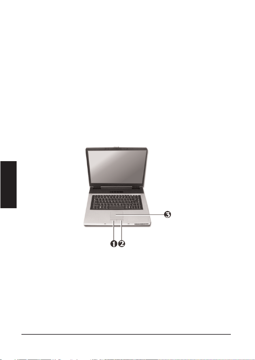
Glide Pad Features
Here how to use the Glide Pad pointing device:
1. The rectangular surface acts like a miniature duplicate of your display screen. To move
the mouse cursor, place the finger lightly on the sensor pad and move in the desired
direction. If you reach the end of the pad, lift your finger and place it back down on the
other side of the pad.
2. To select an item, click on the item by pressing the left button control or by simply tap
ping on the surface once. A light, quick tap always works best. To execute an item, click
the left button twice or do a quick double tap on the surface.
3. To simulate holding the mouse button down (dragging an icon or selection), use the tapand-drag gesture. This feels much like a double-click, except that the finger remains on
the pad after the second tap: Tap, lift, tap, hold and move. The simulated button remains
held as long as the finger remains on the pad.
4. When you press both the Left and Right click button at the same time, the auto Scroll
function will be activated.
• Avoid spilling any liquid on the Glide pad surface and always keep the Glide pad surfa
ce and pointing finger dry from sweat built-up. Also do not expose Glide pad to any magnetic source object.
3.4 Configuring Your Screen Display
The VGA display function of your notebook is based on a high performance AGP local bus
controller and is fully VGA compatible. This controller offers a large set of extended functions and higher resolutions especially useful when you are connecting an external high-resolution and high-frequency CRT or LCD.
English

Please Refer to Section 5 "Installing the Notebook Device Drivers" of Chapter 2 in this
manual for the procedures on how to install the VGA device driver under Windows. After
installing the VGA driver, you would then configure the display resolution or screen size to
match your LCD display panel. This notebook computer model provides Wide screen 15.4”
1280x800 (Wide XGA) resolution panels. You would also probably want to set the amount of
color output to display sharper images and photos.
POSSIBLE DISPLAY CONFIGURATIONS
The table below shows you the possible display resolution you can set when using either the
LCD display or the external monitor (CRT):
• 65,536 or 64K colors is also equivalent to 16-bit high color while 16 million or 16M
colors is equivalent to 32-bit true color.
• You can use the <Fn> + <F3> hot-key to switch the display between LCD only, CRT
only, or both LCD and CRT display.
CHANGING THE DISPLAY PROPERTIES UNDER WINDOWS
To change the display properties of your screen under Windows system, just right-click on
the desktop area and select Properties or go to the Control Panel and click on the Display
icon. The Display Properties dialog box will appear on your screen. Click on the Settings tab
to set your desired configuration. Make sure to follow the configuration table above.
• If you cannot configure the display properties, change the display driver first as men-
tioned on Section 5 "Installing the Notebook Device Drivers" of Chapter 2 in this manual.
Consult your dealer for the latest Windows VGA driver.
English
Display
Possible Resolution
Maximum
Colors
Widescreen
15.4”
1280x800
WXGA LCD
1280x800
1280x768
1280x720
1280x600
1024x768
800x600
16 million colors
16 million colors
16 million colors
16 million colors
16 million colors
16 million colors
CRT Only
800x600
1024x768
1152 x 768
1280x1024
16 million colors
16 million colors
16 million colors
16 million colors

3.5 Knowing the Power Saving Features
One of the great features in your notebook computer aside from its superior performance is
the ability to save energy power. Your computer is designed to incorporate intelligent and
advanced power management functions that turn off power of most components when
system is idle or not in use. This feature not only gives you longer battery hours but cooler
systems and components as well. For more information on how to control the power management features of your computer, refer to Power Options function in Control Panel of
Windows.
The definitions of Standby Mode, Hibernation Mode, and Shutdown are depicted as follows:
Standby Mode
Standby Mode is mainly for power saving. When the Standby Mode is activated, your display and hard drive are shut down and all open applications and documents are stored in
RAM (Random Access Memory). This allows your notebook to wake up quickly, but a low
level of power is required to maintain this suspended state. How quickly your system powers
down into Standby mode is up to you by setting proper times in Power Options of Control
Panel in Window. While the notebook is in Standby mode, the LED of power indicator flashes. To resume your working again, you can press the power button to return your work to
the screen where you left off.
Hibernation Mode
In Hibernation mode, all system devices are powered down and the contents of RAM are
stored on your hard drive. Hibernate mode uses less power than Standby mode, but takes a
bit longer time to resume. When your notebook goes into hibernation, Windows saves your
entire desktop state before powering down your computer. You don’t need to save and close
each document before you put your notebook into hibernation. When you press power button
again, system will bring your notebook out of hibernation. You'll find your applications and
documents open on your desktop exactly as you left them.
• Hibernation is enabled by default. To verify that Hibernation is enabledd, Click Start,
point to Settings, and then click Control Panel. Choose Power Options icon, then click
on the Hibernate tab. IF the chock box of Enable Hibernate is selected, the
Hibernation mode is enabled.
Shutdown
All power has been turned off from the notebook. This means that no power including external AC power source and battery power source will be consume by the notebook.
3.6 Working with the Built-in HDD
Your notebook computer is equipped with a built-in large capacity 2.5 inch IDE hard disk
drive where you store or install your computer operating system and all application software
English

programs. You need to format the hard disk before using. The internal hard disk is normally
assigned as Drive C after formatting. Sometimes divided into two partitions, adding a Drive
D. Since your computer supports different hard disk capacities (up to 80 GB), you also need
to setup the disk type first on your computer’s BIOS SETUP program before formatting the
disk drive. Your computer supports Auto-detect hard disk type, so you do not need to set it
manually. Your dealer should already have done all of this for you. You can refer to Chapter
6 on how to run the BIOS SETUP program.
You can increase the system’s storage capacity by replacing the standard hard disk drive with
a drive of greater storage capacity.
• If you wish to replace your hard disk, contact your local dealer for more information
about this dealer-installable device.
• Always turn off your computer first before removing the hard disk drive. Failure to do
so will damage the computer and the hard disk. Avoid jarring or moving the computer
while the hard disk is still being accessed.
3.7 How to Access the Optical Drive
Your system ships with an optical disk drive installed on the left side of your computer. You
would normally use the drive for installing operating system and software application programs.
To insert and remove a disc on the drive:
1. Make sure the computer is turned on. Press the eject button found on the door cover of the
English

combo drive. The CD tray mechanism will pop-out slightly and slowly pull out the whole
length of the tray.
2. Place the disc on top of the CD tray with the label side facing up. Gently press the compact disc onto the center spindle to secure the disc.
3. To remove the disc, press on the center spindle and pull up the disc from the side until the
disc snaps out of the spindle lock.
• If the eject function is disabled by software or a power failure occurs, the Emergency
Eject Hole allows you to manually remove a CD from the reader.
4. To close the combo drive, simply push the CD tray inside. The combo drive LED will
activate when the disc is detected. Wait until the LED has turned off and then start to read
the disc.
How to care the CD
When you handle CDs, pay attention to the following guidelines:
• Always pick up the CD by its edges.
• Avoid scratching or soiling either side of the CD.
• Do not write with the hard ball-point pen or apply labels on either side of the CD.
• Keep the CD away from direct sunlight or high temperatures.
• Clean fingerprints or dust from the CD by wiping it with a soft cloth.
The above points also apply to other optical storage media.
• The Combo drive is a Class 1 Laser Product.
3.8 ExpressCard
WHAT IS EXPRESSCARD ?
The ExpressCard is a newly developed PC Card interface, its connector has just 26 pins and
the interface has a potential transfer rate of up to 500 MB/sec (or 250 MB/sec in each direction) using a single-lane PCI Express link. Its form factor is up to 40 percent smaller than a
PC Card, which allows ExpressCard modules to be included in smaller host systems.
Designed for both desktop and mobile use, ExpressCard use either USB 2.0 or a single lane
PCI Express technology.
The ExpressCard standard was developed by PCMCIA member companies including technology leaders, system manufacturers, card manufacturers, from all other parts of the PC Card
industry.
English

Dimensions of ExpressCard
Current CardBus PC cards are 54 millimeters wide. ExpressCard can divided into two categories, based on width. Most designs will use the ExpressCard 34 design, which sets the
width at 34 millimeters. For some applications, the wider ExpressCard 54 standard will be
used to produce cards that can handle the higher thermal requirements of those applications.
All ExpressCard modules are 5mm thick but the standard also allows for card developers to
build longer 'extended' modules.
Native Bus Connection
The ExpressCard standard supports both the USB 2.0 and PCI Express interfaces. Card
manufacturers are able to choose whichever bus is appropriate to their application; the performance of PCI Express, or from the wide range of solutions supported by USB. All host
PC ExpressCard slots will support cards using either interface. The host platform no longer
needs to incorporate a bridge chip between the chipset and the socket. PCI Express and USB
2.0 are fully hot-pluggable.
To support the broadest range of applications there are two sizes of module. Both are smaller
that today's CardBus card. The smallest card, the ExpressCard/34 module, is almost half the
size of a CardBus card. This size is suited to a very broad range of applications covering
communications, media, and general purpose.
English
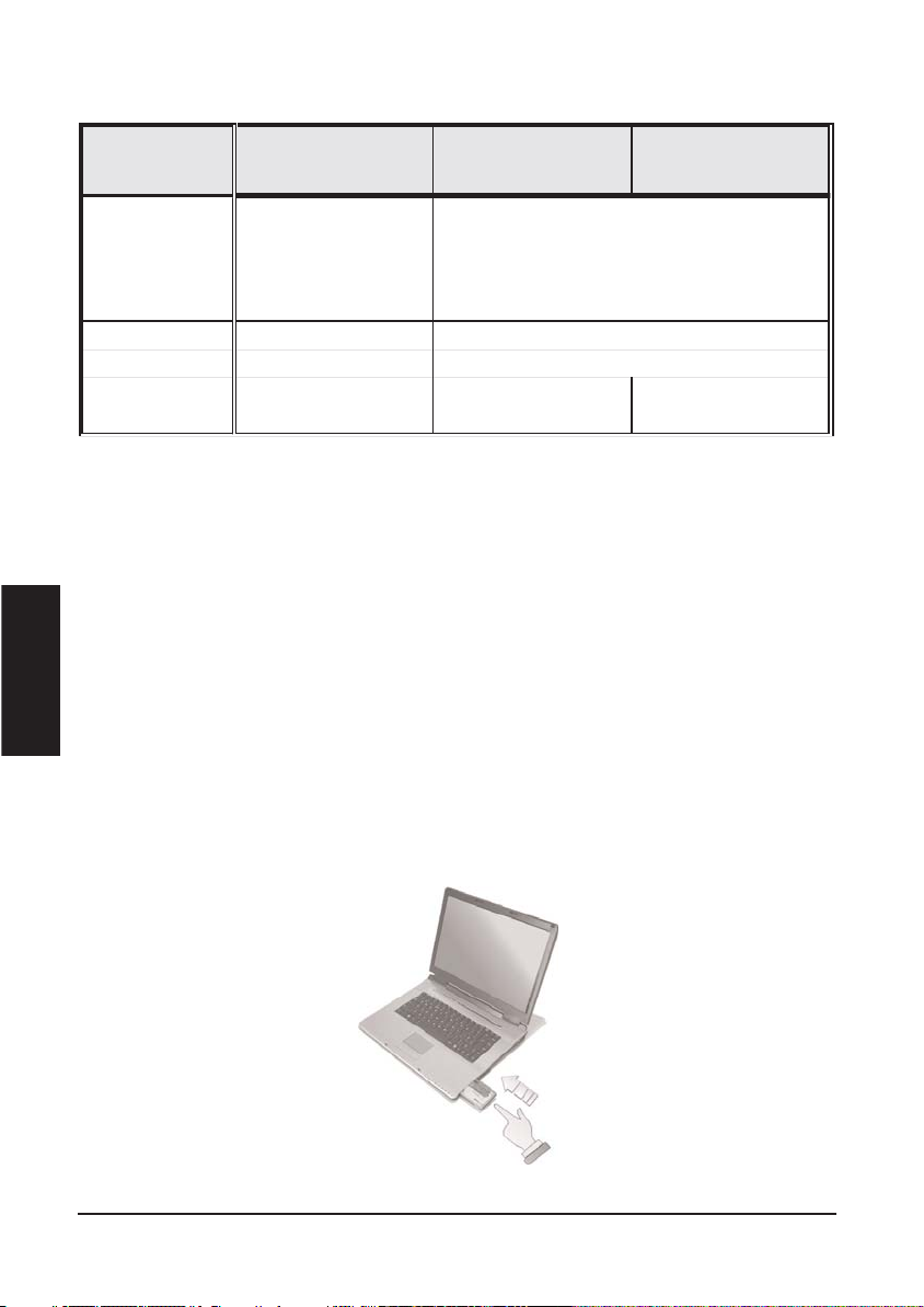
A big part of "just working" will be the existing software support. Both Windows XP and
Windows 2000 already support the ExpressCard specification, although Windows 98 and
Windows Millennium Edition do not.
INSERTING AND REMOVING A EXPRESSCARD
Your computer includes hot swapping capability, that allows you to exchange cards while the
computer is turn on and start using it immediately.
Inserting ExpressCard
To insert a ExpressCard into the ExpressCard slot:
1. Locate the ExpressCard slot cover on the right side of the computer.
2. Insert the side of ExpressCard with the 26-pin socket into the ExpressCard slot. The face
label of the card should also be facing up.
3. When the full length of the card is almost inside the slot, push firmly but slowly, to ensure
full connection with the computer. The ExpressCard will be automatically detected. and once
the needed driver is installed, it will generate a beep sound to indicate that the card is detected.
English
PC Card
(CardBus, Type II)
ExpressCard/54
ExpressCard/34
Data
Tran
sfer
rate
132 Mbps
500Mbps (or 250Mbps in each direction)
Connector pins6826
Port Type
Parallel
Serial
Dimensions
(HxWxD)
54mmx86mmx5mm
54mmx75mmx5mm
34mmx75mmx5mm

Removing ExpressCard
To remove a ExpressCard from the ExpressCard slot, you should first disable the
ExpressCard card setting in the system as described followings:
1. Double click the ExpressCard icon on the right bottom side of the task bar.
2. Select the socket from the list that you want to remove, and click Stop button. The system
then disables the function of ExpressCard card.
3. Then you can remove the inserted ExpressCard, push the button found on the right side of
the ExpressCard slot to release the eject button. Then push it again to release the
ExpressCard.
4. When the ExpressCard has moved out a space out of the slot, hold the edges of the card
and slowly slide it out.
• The power consumption of ExpressCard/54 is about 2.1W, while the consumption of
ExpressCard/34 is about 1.3W. To save energy, press the button to disconnect the card
when it is not in use.
3.9 Using Flash Memory Cards
WHAT IS FLASH MEMORY CARD?
Flash Memory is a memory storage media. It is used by most digital camera, moreover, it can
replace the traditional floppy disk. Flash memory card is built with different form factor and
brand name. Their size is smaller than PCMCIA card. This computer supports most of the
flash memory card, including SD, MMC, MS (Memory Stick), and MS_Pro card.
The 4 in 1 card slot is used by the following cards as SD, MS (Memory Stick ), MMC, and
MS_Pro.
• For a single moment, only one card can be inserted into the 4 in 1 card or CF slot
English

Inserting Flash Memory Card
To insert a flash memory card into the slot is similar to ExpressCard. You only need to pay
more attention whenever insert the flash memory card into the slot with the correct side.
For MMC and SD card, you should position the copper connector at the bottom side. For
Memory Stick card, you should position the copper connector at the topside. All of these
cards should be located at the center of the slots in inserting.
Only one correct side can be accepted for the 4 in 1 card slots. If you cannot insert the card
into the 4 in 1 slot or you had inserted the card but it is not recognized by the computer, please remove the card and turn the card upside down and insert it again. To prevent the damage made both on card and the slot, never forced an entry into the slot with incorrect side.
Removing Flash Memory Card
It is similar to ExpressCard for removing a flash memory card from the slot. You should first
disable the card setting in the system as described in the former section.
To remove the flash memory card, you should only pull out the card by finger, there is no
release button for flash memory slot.
English
Slot
Card type
Copper connector
4 in 1
SD (Secur e
Digital)
MMC
(Multi Media
Card)
MS (Memory
Stick)
MS_Pro
Bottom side
Bottom
Top side
Top side

Fun with Multimedia
This chapter lets you make full use of all the multimedia features of your computer in having fun and excitement during
work or leisure. You will learn how to mix and match the
built-in sound system, use Combo drive in creating an exciting full multimedia presentation.
English
CHAPTER
4

4.1 Notebook Multimedia Features
Your notebook computer is rich in multimedia features that make your computing fun, comfortable, exciting and easy. Your computer is well able to perform all multimedia tasks
through the following:
• Intel® Pentium® M Processor Dothan
• Up to 2GB DDR2- SDRAM
• DVD/CD-RW Combo or DVD Dual (Optional)
• Integrated Intel 915GM graphics engine.
• 16-bit Audio Sound System with built-in speaker and microphone.
4.2 Audio Sound System Features
Your computer has a built-in 16-bit stereo sound controller that allows you to record, store,
and playback voice, music and other sound effects with built-in mixer controls. An integrated
full-duplex microphone and twin mini-speakers are also built-in into your computer to allow
you to record and playback sound anytime and anywhere.
On the left side of your computer, you will find the audio ports that include the following:
• External 1/8-inch microphone jack that connects external microphone for recording purpose.
• Earphone or headphone jack for personal listening.
• SPDIF out port for digitized audio signal transmission.
• Sound volume adjust by K/B hot-key
4.3 Setting up the Audio Driver Properties
Before you can start using the audio capabilities of your computer, you need first to setup
properly the audio driver after installing Windows. If you bought your computer with
Windows pre-installed, it is most likely that your dealer have configured the sound driver for
you. If not, you must refer to Chapter 2 on how to setup the sound drivers for Windows.
4.4 Windows Multimedia Programs
Windows provides several multimedia programs that you can run with the built-in features of
your computer. Pointing the Start button, Programs, Accessories, then Entertainment, you
will find the Multimedia programs group. (The section below use Window XP as examples)
English

Figure 4-1 Entertainment Programs Group
The standard multimedia components are as follows:
• Windows Media Player - for playing sound, video and animation files
• Sound Recorder - for recording sounds and playback
• Volume Control - for adjusting the volume of mixer
+ For more information on how to operate these multimedia components, run the program
and click on the Help menu.
4.5 Recording Sounds
Your computer allows you to record voice and other sounds in several ways and stores them
as files on your hard disk. These voice or sound files can then be played back through the
internal speaker or earphone jack using an external speaker, headphone, or earphone set. You
can also use the files as voice annotations on many applications for more real presentation.
This section will describe briefly how you can record sounds under Windows operating
system.
To record sounds, you need to run the Sound Recorder program from the Multimedia program groups. The control buttons of the Sound Recorder are simple to understand which
comprise of the Fast Rewind, Fast Forward, Play, Stop, and Record buttons. Click the Help
menu on how to operate the Sound Recorder.
English

Figure 4-2 Sound Recorder
The Sound Recorder also allows you to record sound from different input audio source like
the following:
• From the external microphone
• From the Combo drive
Since you could record sound from different input sources, you must first set the proper
audio input recording device under the Recording Control panel. To do this:
1. Double-click on the Volume Control on the taskbar or click Start button, then point to
Programs, Accessories, Entertainment and then click on Volume Control.
2. Click Properties in the Options main menu.
3. Click the round button for Recording and tick off each component that list in the "Shows
the following Volume Controls" box.
Figure 4-3 Audio Properties
English

4. Click OK and the Recording Control dialog box will appear. Here, you will select the
input device for the recording source. If you want to record from the Combo drive with audio
music, you must click on CD Player.
Figure 4-4 Recording Volume Control
USING AN EXTERNAL MICROPHONE
Your computer allows you to connect an external microphone for high quality recording.
The external microphone jack is found on the left side of your computer. Use only microphone with 1/8-inch mini-jack connector. Follow the same procedure for recording voice.
USING THE BUILT-IN COMBO DRIVE
You would normally use the Combo drive for recording audio music from the Audio CD.
Follow these steps:
1. Activate CD Player volume on the Recording Control as discussed earlier.
2. Run the Sound Recorder program.
3. Insert the audio CD into the Combo drive. Unless you have disabled the CD auto-insertion
notification for supporting Suspend mode, the CD Player should automatically run after you
have inserted an audio compact disc and will start playing the audio CD.4. Select the starting
point where you want to start recording.
5. Switch to the Sound Recorder and press the Record button.
6. Switch immediately to the Windows Media Player and press the Play button. You can
adjust the volume control so you can also hear the music while in recording.
English

Figure 4-5 Play Audio CD by Windows Media Player
4.6 Playing Audio and Sound
Your computer has built-in twin speakers to playback audio and sound. You can also adjust
the volume manually by adjusting the volume control hotkeys found on the keyboard.
For more quality sound output, you can choose to connect an external amplified speaker or
earphone from headphone jack. Always minimize the volume first before placing the phone
set to your ear.
USING THE WINDOWS MEDIA PLAYER
The easiest way to playback multimedia media files is to run the Windows Media Player.
Follow these steps:
1. Click on Start, point to Programs, Accessories, and then Entertainment.
2. Click on Windows Media Player to start program.
3. Click on the File menu and select the file you want to play.
4. When the file is recognized and open, click on the Play button to start playback.
4.7 Playing Video and MPEG Files
Your computer is capable of running video motion files as well as MPEG (Motion Picture
Expert Group) files on CD, DVD, or CD-RW. By using software MPEG program, you can
English

watch real full-motion picture on your computer. You can also run the Windows Media
Player under the Entertainment programs group as well to show all media device programs.
Figure 4-6 Windows Media Player
4.8 Using DVD
DVD is the breakthrough in superb full-motion picture playback. One disc can contain at
least 4.7GB of information, capable of holding one full-length movie with soundtracks,
subtitles, and different languages. Much more, the DVD-ROM drive of your computer is
backward compatible with CD-ROM drive so it allows you to use any CD as well. It also
works the same as the CD-ROM.
To playback DVD titles, you would need a software MPEG-2 program and the DVD-ROM
drive at least. Your Notebook computer has installed Windows XP for operation system and
its Windows Media Player supports DVD’s playback..
You can use Windows Media Player to watch DVDs on your Notebook computer. Like a
conventional DVD player, by using the Player, you can skip to specific titles and chapters,
play sequences in slow motion, gain access to special features, and switch audio and caption
languages. In addition to these conventional DVD player tasks, you can also retrieve information about each disc from the Internet.
English

Figure 4-7 To play a DVD
On the Play menu, point to DVD, VCD or CD Audio, and then click the drive that contains
the DVD. In the Playlist pane, click a DVD title, or chapter name, if appropriate.
To eject a disc, on the Play menu, click Eject. To play a selected title in a DVD repeatedly,
on the Play menu, click Repeat. A check mark appears next to the command to indicate it is
turned on.
4.9 Using Rewritable Optical Disk Drive
DVD/CD-RW Combo or DVD+RW combo drive is a device that can write digital data to
CD-R and CD-RW or DVD+R and DVD+RW media. With this device, you can backup your
own data to CD-R or CD-RW disc for mass data storage and safely retaining. The CD-R disc
can be written several times until the CD-R is full; the CD-RW disc, furthermore, can write
and erase data repeatedly. Please refer to the related user manual about the CD-RW software.
• Please pay attention to the copyright of the software or data you want to backup.
Backup or distribute the software or data might be illegal according the restriction of
the law.
English

Connecting to Peripherals
This chapter describes how you attach peripheral devices to your notebook. You can attach a printer or
mouse; connect an external monitor and keyboard, or
any other peripheral device. You will learn how to use
these peripheral devices with the step-by-step instructions depicted in this chapter.
English
CHAPTER
5

5.1 Using the USB Port
USB (Universal Serial Bus) is a hardware interface that enables you to connect multiple
devices (such as printers, mice, keyboards, storage devices, joysticks, digital cameras, and
video conference cameras, etc.) to your notebook computer, and up to 127 devices can be
attached. Besides, USB’s hot swap capability allows everything to be plugged in and
unplugged without turning the system off.
Microsoft, HP, Compaq, Intel, Agere, NEC and Philip are seven core members of USB-IF to
have worked on USB 2.0 standardization. USB 2.0 offers data transfer rate up to 480Mbps
(megabits per second) compared to USB 1.1 devices, which transfer at speeds of 12Mbps.
So, you could know that USB 2.0 can transfer data between the computer and its peripherals
40 times faster than USB 1.1. However, USB 2.0 is fully backward compatible, you will be
able to use a USB 1.1 device in a USB 2.0 compliant system.
• Depending on your operational requirements, you may need to disable other ports
in order to release system resource for the USB port.
• The USB bus distributes 0.5 amps (500 milliamps) of power through each port. For
the purpose of power saving, please disconnect your USB device while not in use.
5.2 Using an External Monitor Port
Your computer has a 15-pin Monitor port for supporting any external CRT or LCD color
monitor. You need a display signal cable (usually provided with the monitor). One end of the
cable must have a 15-pin connector for the system.
To connect an external monitor:
1. Turn off your computer and make sure the monitor power switch is turned off.
• The notebook computer must be powered off or suspended while the monitor is
being connected. Although you can connect the external Monitor without power off the
computer andthe external monitor, however, it is harmful to both devices and it shortens the life of these devices.
English
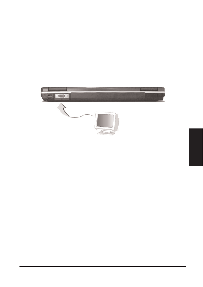
2. Connect the connector cable of the monitor to the VGA port at the back of your computer.
Secure the cable connection with the screws provided.
3. Connect the monitor power cable and plug it into a properly grounded wall outlet.
4. Turn on the power of the monitor.
5. Turn on your computer. Both the LCD panel and the monitor screen will show the display.
Your computer is set at default to run at simultaneous display mode.
6. If you only want to show the display on the external monitor or projector and shut off the
LCD display, you can use the <Fn> + <F3> hot-key to switch display type between LCD and
external monitor. Keep pressing the hot-key until you get the display to external monitor only.
• Refer to Chapter 3 regarding the possible External CRT resolutions and how to
change the display properties.
5.3 Using the IEEE 1394 Port
IEEE 1394, also known as FireWire, is a high-bandwidth serial bus developed by Apple and
Texas Instruments. IEEE 1394 supports 100, 200, and 400 Mbps (Megabit per second) transfer rates and is widely used for downing video from digital camcorders to the computer. In
addition to its high speed, IEEE 1394 enables isochronous (real-time) data transfer. This
makes it ideal for devices that transfer high-bandwidth of data in real-time, such as video
devices. It supports both Plug-and-Play and hot plugging, and also allows for the connection
of up to 63 devices.
With built-in IEEE 1394 port, this computer enables the peripheral devices in transmitting
digital video data or data backup. The Windows system will automatically recognize it after
installing a suitable driver for it. Please visit Microsoft's web site for more information about
it. Moreover, you should install the driver of peripheral device to connect with the IEEE
1394 port, for details please refer to the manual that comes with your peripheral device.
English

• Please make sure that the external IEEE 1394 HDD box you purchase on local elec
tronic store should provide external power adapter. There are different types of
IEEE1394 HDD box and hard disk from different manufactures, the power con
sumption has varied range. If the power of the external IEEE 1394 HDD is supplied
from the USB of this notebook, it may not run properly.
5.4 Using the TV Port
Also found at the right of your computer is one TV port (s-video).
To display your computer screen on the TV, please connect the TV port of this notebook to
the Video Input of the TV set. You can press <Fn> + <F3> key continually to switch between TFT, external monitor, TFT + external monitor and TV only. Keep pressing the hot-key
until you get the display to external TV only.
Or you can setup the detail by operate the computer as follows.
1. Turn off your computer and plug one end of the s-video jack cable to the end to the input
video jack of your television set.
2. Turn on your computer and your television set.
3. Click the Start button, then point to Settings, and click Control Panel.
English

4. Double-click on the Display icon and point to Setting tab.
5. Click Advanced button and point to Displays tab. You can see the TV icon on the screen.
6. Please click the red button above the TV icon. Click OK, Windows now automatically
detect the TV port and enable this function.
5.5 Using the External Audio System
At the left side of your computer, you will find the built-in audio ports. You can connect
Microphone jacks, earphone or powered speaker.
To connect to a audio jack:
1. Locate the audio port (Microphone, Headphone) that you want to use to the target device.
2. Plug the jack into the port on the left side of the system.
• If you use external speakers and experience the sound distortion or feedback, please
lower the volume. Some factors is caused by too close locating the microphone and
speakers from each other, moving away the external audio option from the unit may
also help.
5.6 Using the LAN Port
This notebook comes with an internal 10Base-T/100Base-TX LAN module that connects your
computer to other computers/networks through a local area network (LAN) and supports data
transfer rates at 10Mbps and can be up to 100Mbps. The 10Base-T standard also called Twisted
Pair Ethernet is connected with RJ-45 connectors. The 100Base-TX is based on the older Ethernet
standard. Because it is 10 times faster than Ethernet, it is often referred to as Fast Ethernet.
The built-in LAN module provides a standard RJ-45 connector.
To connect the twisted-pair cable to your LAN port:
1. Locate the twisted-pair cable in the accessories box in notebook shipping carton. Each end
of the cable has a RJ-45 connector.
2. Connect one end of the cable into the network wall outlet or HUB.
3. Connect the other end of the cable into the computer RJ-45 LAN port.
English

5.7 Using the Wireless LAN
Wireless LAN is the major breakthrough in computer communication technology. It lets user
connect to the LAN environment without using any wire to traditional RJ-45 jack. User can
enjoy the wireless connection within the range of Access Point (AP) of LAN.
Access Point (AP) is the wireless transmission and receiving device, it generally connects to
the server of a LAN environment or act as a LAN hub with wireless connection. Access
point can be set in an office environment, airport, major railway station, etc. that depends on
the construction of each country. In most case, you probably can use it at office, please consult with the network department of your company for more details.
This computer integrates built-in 802.11 b/g wireless LAN module. IEEE 802.11b standard
supports 11 Mbps wireless connection speed. However, IEEE 802.11g supports 54Mbps
wireless connection speed, and is backward compatible with the slower 802.11b. Wireless
LAN module is similar to LAN module. You need to install software driver before using it.
Please refer to chapter 2.5 on how to install the driver.
5.8 Using the Modem Port
This notebook comes equipped with a 56K internal fax/data modem that allows you to communicate with others via fax, email, or to connect to an online service or bulletin board.
The built-in fax/data modem provides on standard phone connector.
To connect the analog phone cable to your modem:
1. Locate the analog phone cable in the accessories box in notebook shipping carton. Each
end of the cable has a RJ-11 connector.
2. Connect one end of the cable into a standard wall outlet.
3. Connect the other end of the cable into the computer modem port.
• The speed of data transmission is dependent on the quality of telephone lines.
Digitally terminated lines improve the speed of data transmission. Contact your ser
vice provider for more information.
• The analog phone cable is an industry standard cable. Longer cables are available
at your local electronics store.
English

Customizing Your Notebook
Your computer uses the Phoenix BIOS Setup program that allows you to set several system configuration in changing the way your computer performs.
This includes you r system time and date, disk drive
configuration and password setup. This information is
then stored in the CMOS RAM and will remain permanent unless you change it again. This chapter discusses on how you will activate the BIOS Setup program and change the system configuration to suit
your desired operation. You must be careful to set the
configuration properly in order for your computer to
run smoothly. If you are not sure of any settings, contact your dealer.
English
CHAPTER
6

6.1 Running the BIOS Setup Program
Your computer is likely to have been properly setup and configured by your dealer prior to
delivery. However, you may find it necessary to use the computer’s BIOS (Basic InputOutput System) Setup program to change system configuration information, such as the
current date and time, or your hard disk drive type. The Setup program can be accessed
when you power on the system and pressing the <F2> function key.
The settings that you specify within the Setup program are recorded in a special area
memory called the CMOS RAM. This memory is backed up by a battery so that is will not
be erased when you turn off or reset the system. Whenever you turn on the computer, the
system will read the settings stored in the CMOS RAM and compare them to the equipment
check conducted during the Power On Self Test (POST). If an error occurs, an error message
will be displayed on the screen, and you will then be prompted to run the Setup Program.
As the POST (Power-On Self Test) executes during the boot up process, the screen will display the following message:
Press <F2> to Enter SETUP
Press the <F2> key to run the BIOS Setup program. The BIOS Setup program is organized
into five menus which you can select using the <-- and --> keys. To move from one option to
another, you use the up and down arrow keys while using the <F5> and <F6>, or <+>and <> keys to change the settings. On the right hand side of the screen are some brief help descriptions of each item you want to change.
On the BIOS Setup program, you will find the following parts on the screen:
• Item Specific Help
The right side of the screen. This area describes each parameter and its available settings.
• Menu Bar
The top line of the screen. Each of the five selections displays its own screen.
• Parameters
The left side of the screen. This area lists the parameters and their current settings.
• Key Status Bar
The bottom part of the screen. These lines display the keys available to move the cursor,
select a particular function and so forth.
To exit the BIOS Setup program, simply press the <Esc> key and select from the Exit menu
whether you want to Save changes and exit; Discard Changes and exit.
English

6.2 Using the Main Menu Setup
• System Time
Allows you to change the system time using the hour:minute:second format of the computer.
Enter the current time for reach field and use the <Tab>, <Shift>+<Tab>, or <Enter> key to
move from one field or back to another.
You can also change the system time from your operating system.
• System Date
Allows you to set the system date using the month/date/year format.
Enter the current time for reach field and use the <Tab>, <Shift>+<Tab>, or <Enter> key to
move from one field or back to another.
You can also change the system time from your operating system.
• SATA Hard Disk
This field display various parameters for the hard disk drive. If type [Auto] is selected, the
system automatically sets these parameters. If type [User] is selected, Cylinders, Heads and
Sectors and other value can be edited.
• CD/DVD
This field is for information only as the BIOS automatically detects the optical drive.
• System Memory
This field reports the amount of base (or conventional) memory found by the BIOS during
Power-On Self-Test (POST).
English

• Extended Memory
This field reports the amount of extended memory found by the BIOS during Power-On
Self-Test (POST).
• CPU Type
This field reports the CPU type information detected by the BIOS during Power-On SelfTest (POST).
• CPU Speed
This field reports the CPU speed information detected by the BIOS during Power-On SelfTest (POST).
• BIOS Version
This field is for information only as the BIOS displays the BIOS version during the PowerOn Self-Test (POST).
6.2.1 INTERNAL HDD SUB-MENU
Use the Type field to select the drive type installed. You can select different drive types as
CD-DVD, User, Auto or None by pressing <Space> bar. Set this option to Auto so your
computer will automatically detect the drive type during power on. Set this option to None
when your computer is not installed any devices. Press <Esc> to return to the Main Menu.
English

6.3 Using the Advanced CMOS Setup
• Summary Screen
Displays system configuration on boot.
• Quiet Boot
Lets you specify the boot screen to Logo screen or POST screen by choosing Disabled or
Enabled, respectively.
• PXE OPROM
Lets you specify Enabled or Disabled for activating or inactivating PXE OPROM Device
function when system is booting. Please set it to default value as “Disabled”.
English

6.4 Security Menu Setup
• Supervisor Password Is
Set/Clear selections show that the notebook is under controlled by Supervisor Password or
not.
• User Password Is
Set/Clear selections show that the notebook is under controlled by User Password or not.
• Set Supervisor Password
Supervisor password gives you the authority in accessing the setup utility. You also need to
enter this password in system booting and resuming from suspend mode. When you press
<Enter> in this field, the Set Supervisor Password dialog box appears. Enter a new password with up to 8 alpha-numeric characters, and then re-enter it for confirmation.
• Set User Password
This field is only available when Supervisor Password has set. Enter the user password when
boot the system or resume from suspend mode. But if the Write Protect is set in the Fixed
disk boot sector field, you should enter a supervisor password to access the fixed disk when
boot the system or resume from suspend mode.
• Fixed Disk Boot Sector
If you set this field to Write Protect, the write protect boot sector on hard disk will protect
against viruses. In this situation, only the supervisor can access the Boot Sector of fixed disk.
• Password on Boot
If you set this field to Enabled, your computer will always ask for the password every time
you boot your computer.
English

6.5 Using the Boot Setup
This item allows you to set the search drive sequence where the system will try to boot up
first.
This page allows you to set the search drive sequence where the system will try to boot up
first.
To select the boot device, you can use the up or down arrow key, then press <+> to move up
the device in the list or press <-> to move down the device in the list. To exit from this menu,
press <Esc>.
6.6 How to Exit the Setup Program
There are two choices to escape from the Setup program.
• Exit Saving Changes
Saves all changes to CMOS while running the BIOS setup program and exit from the system
setup program.
• Exit Discarding Changes
Allows you to discard all changes made while running the BIOS setup program and exit from
the system setup program.
English

• Load Setup Defaults
Lets you load the default values for all setup items.
• Discard Changes
Reverts to previously selected settings.
• Save Changes
Saves Setup data to CMOS.
6.7 How to Upgrade the BIOS
Your computer uses EPROM Flash BIOS chip that allows you to easily upgrade the BIOS
program. When you update the BIOS, any customized settings you made are lost.
To upgrade the BIOS:
1. Insert the BIOS Update diskette into the diskette drive.
2. Power on the system with the diskette in the diskette drive.
3. On the DOS prompt, type the following command.
A:\>Phlash XXXXXX.ROM (BIOS filename) or
A:\>XXXXXX.BAT (Batch file for BIOS file)
Press <Enter> to run this BIOS utility. After the system has been successfully run this program, a message similar to the following appears:
Flash memory has been successfully programmed, press any key to restart the system. If the
system does not restart, turn it off, then turn on again.
4. Press any key to restart this system.
Contact your dealer for the latest BIOS update file.
English

Using Options
This chapter describes the advanced features and
expandable architecture in your notebook. You can
upgrade your system for specific requirements.
English
CHAPTER
7

System Upgrade
This section provides some steps in doing system upgrade for your notebook computer. The
upgrade procedures include the following:
7.1 Memory Upgrade
Your notebook computer offers 200-pin SODIMM (Small Outline Dual Inline Memory
Module) at least 256MB DDR2-SDRAM. The memory compartment is located inside your
computer. The table below lists the possible combinations of different memory module and
memory size.
• Please contact dealer for changing or adding DDR2-SDRAM module. It is not avai
lable for users to change it by themselves.
Based Memory Installing Memory Total
256 MB 0 MB 256 MB
256 MB 256 MB 512 MB
256 MB 512 MB 768 MB
256 MB 1024 MB 1280 MB
512 MB 0 MB 512 MB
512 MB 256 MB 768 MB
512 MB 512 MB 1024 MB
512 MB 1024MB 1536 MB
1024MB 0 MB 1024 MB
1024MB 256 MB 1280 MB
1024MB 512 MB 1536 MB
1024MB 1024MB 2048 MB
INSTALLING MEMORY MODULE
Your computer comes with standard 256 MB, 512MB or 1024MB of synchronous DDR2
SDRAM. You can increase system memory to a maximum of 2048 MB in the system, by
installing two small outline double inline memory modules (SO-DIMMs) with installed base
memory in the system.
The 256MB, 512MB and 1024MB memory modules are available:
To install the memory module:
1. Make sure the system is powered off, the battery also is removed and that no peripheral
devices are attached.
2. Turn the computer upside-down and locate the screw that secures the DIMM door at the
underside of the notebook.
English

3. Remove the screws and open the DIMM cover by your finger.
4. Locate the memory module into the empty memory module sockets. (Your system comes
with one memory module already installed in the socket.)
• Avoid touching the exposed components inside the system. Doing so may damage the
system.
5. Insert the connector of the memory module into the socket. Make sure the notch of the
memory module fits the nose of the socket.
ü Hold the memory module at a 30-degree angle and push its connector into the
memory socket of the notebook.
ü Press down on the edge of the memory module until the locking
tabs on both sides is locked.
6. Put the DIMM door back and secure the screw on the DIMM door.
7. Turn the system over.
To remove a memory module, push the locking tabs aside from the memory module until the
module pops up. Then, remove the memory module.
7.2 Hard Disk Upgrade
Your notebook computer offers one 2.5" format, 9.5mm height hard disk. If the volume does
not fit your need or it is crashed, you can upgrade it by replacing with new hard disk. Please
do the following steps to change it.
1. Remove the screw and open the cover by lifting its upper side cover.
English

2. Take out the hard disk from the compartment by finger carefully
3. Remove the connector from the hard disk gently.
4. Remove the crane screws located at each side of the hard disk.
5. Rotate and tighten the crane screws to the new hard disk.
6. Attach the connector to the new hard disk precisely.
7. Place the hard disk back to the compartment.
8. Cover the lid, then rotate and tighten the screws.
9. Set the boot device as DVD/CD-RW Combo drive and Primary Master as Auto on BIOS
setup menu. Please refer to Chapter 6 about the setting of BIOS setup menu. Then, boot the
system by using WinXP CD-ROM and the system will detect the hard disk automatically and
prompt you how to format the new disk.
• Please tighten the screws located at each side of the hard disk before operating the
hard disk. Any vibration may cause damage for the running hard disk.
• Please contact dealer or certified technician for changing the hard disk drive. The
damage of changing HDD resulting from users may not be under warranty
7.3 Wireless Module Installation
This computer uses mini-PCI wireless LAN module at the bottom of this notebook for wireless connection.
• Please contact dealer for adding or changing this module. Any damage that caused
by inappropriately adding or changing this module will not be under warranty
English

Caring for Your Notebook
Your Notebook PC is a fully IBM compatible portable personal computer with the latest features in
mobile computing and multimedia technology.
Lightweight and compact, your Notebook PC
runs on a whole wide range of general business,
personal productivity, and professional applications, it is ideal for use in the office, at home, and
on the road.
Your Notebook PC also allows you for several
levels of customization and expansion that are
previously available only on desktop PCs.
English
CHAPTER
7

8.1 Important Safety Instructions
Portable computers take the most beating from end users. This section gives you detailed
information about how to maintain a safe working environment while using the notebook
computer. You can maintain its condition and performance by following these guidelines.
Please read it carefully to ensure maximum safety.
• Before cleaning the notebook computer, make sure it is disconnected from any external
power supplies (i.e. AC adapter, car adapter and so on).
• When cleaning, do not use liquid or sprayed detergent for cleaning. Instead, use moisture
sheet or a cloth for cleaning.
• The socket-outlet shall be installed near the notebook computer and shall be easily acces
sible.
• Please keep the notebook computer from humidity.
• Lay the notebook computer on a reliable surface when installing. A drop or fall may
cause injury.
• The openings on the enclosure are for air convection hence the notebook computer can be
protected from overheating. DO NOT COVER THE OPENINGS.
• Be careful of using power supply. The notebook computer has specific power requirements.
• Use only a power adapter approved for use with this notebook computer.
• The power adapter may have a 2-prong plug. This is an important safety feature. A com
patible outlet is required. If it is not available, find a qualified electrician to install one.
• While unplugging the power cord, disconnect it by the plug head, not by its wire.
• Make sure the socket and any extension cords you may use can support the total current
load of all the connected devices.
• Though your AC adapter is suitable for universal international voltage, it still requires a
stable and continual power supply. Make sure the voltage of the power source when con
nect the notebook computer to the power outlet. If your are unsure of your local power
specifications, consult your dealer or local power company.
• Place the power cord in such a way that people can not step on it. Do not place anything
over the power cord.
• All cautions and warnings on the notebook computer should be noted.
• If the notebook computer is not in use for a long time, disconnect it from mains to avoid
possible damage by transient over-voltage.
• Never pour any liquid into openings as this may cause fire or electrical shock.
• Never open the body of notebook computer. For safety reason, the notebook computer
should only be opened by qualified service personnel.
• If one of the following situations arises, have the notebook computer checked by service
personnel:
• The power cord or plug is damaged.
• Liquid has penetrated into the notebook computer.
• The notebook computer has been exposed to moisture.
• The notebook computer has not worked well or you can not get it work according to
user’s manual.
• The notebook computer has dropped and damaged.
• The notebook computer has obvious sign of breakage.
English

• Do not leave this notebook computer in an environment unconditioned. Storage tempera
ture above 60ºC (140ºF) may damage the notebook computer.
• An approved power cord has to be used for the notebook computer’s power supply. For a
rated current up to 6A and an equipment weight more than 3 kg, a power cord not lighter
than H05VV-F, 2G, 0.75mm2, has to be used.
• To avoid any damage happened to the internal device, you should first disconnect the AC
adapter and remove the battery pack from the notebook when replacing any internal device.
The sound pressure level at the operator's position according to IEC 60704-1 is equal or less
than 70dB(A).
8.2 Cleaning Your Computer
When it is necessary to clean the plastic case and keyboard, use a soft, lint-free cloth, slightly
dampened with a mild detergent solution or use the contents of any commercially available
computer cleaning kit.
Never use alcohol, petroleum-based solvents, or harsh detergents to clean the notebook. Also
never spray any liquids directly on the computer case, keyboard, or screen. If the liquidcrystal display (LCD) screen has become smeared or dusty, clean the screen by first applying
a mild glass cleaner to a soft, clean, lint-free cloth, and gently wipe the glass. Never apply
liquids directly on the screen surface. Moreover, do not use paper towels to clean the display
screen. Paper can scratch the display screen matte.
8.3 Maintaining the LCD Quality
When it comes to screen problems, heat plays a big part. After a good working session, the
typical routine is to shut the machine and close the cover. But the display surface - no matter
what type it is - and the components inside the computer radiates heat; when you close the
cover, you trap the heat against the screen. Leave the computer's cover open for about ten
minutes while the heat disperses. Make this a habit.
You should also enable the power management of your computer to turn off the LCD power
and display when the system is in inactivity for some time. Adding screen savers is also
acceptable.
Follow the safety guidelines mentioned earlier and how to clean your computer.
8.4 Maintaining Your Hard Disk
Losing your data has the same consequences as a system break down. Users must make it a
habit of doing hard disk maintenance every week or so. Here is some maintenance you could
do:
• Always back up your data files from your hard disk.
• Install the virus detecting program to monitor virus that could tamper your files.
• Use SCANDISK once in a while to correct any errors found in the directory and File
English

Allocation Table. This will also free up space from any unused sectors.
• Never move or raise the computer while the hard disk is being accessed, most especially
don't jar the hard disk as this may cause a hard disk crash.
• Use hard disk maintenance programs like Disk Defragmenter of Windows. These reor
ganize your hard disk by eliminating fragmentation and improving your hard disk access
time.
• Install a system password in your computer so others won't be able to use the hard disk.
8.5 Battery Care Guidelines
The battery pack furnished with the computer requires reasonable care and handling to ensure efficient operation and maximum life. There is a risk of fire and chemical burn if the battery pack is handled improperly.
To ensure that the battery pack endures normal life cycle, always observe the following precautions when handling the battery pack:
• Handle batteries carefully. Do not try to disassemble, crush, puncture, open, drop, mutila
te, short external contacts, disposed of in water or fire, or expose it to temperatures hig
her than 60 C.
• Recharge batteries only as described in this manual and only in ventilated areas. Never
use an external charger other than the one supplied with your computer.
• Do not leave batteries in hot locations for more than a day or two.
• Do not leave your battery in your computer for longer than 1 month without plugging in
the power adapter.
• Do not leave battery in storage for more than 2 months without recharging it to prevent
over discharge. Over discharge will hurt the battery
• Dispose dead battery properly to protect the environment. The batteries contain hazar
dous chemicals and should not be thrown out with household or office trash.
• You should always discharge your battery before recharging it on either of these two con
ditions: first, this is the first time you start to use your battery; second, you had not char
ge the battery for more than 2 months. To discharge the battery, please execute the
"Battery Refresh" function in the BIOS Setup Utility.
8.6 When You Travel
For safety and convenience when traveling, please follow these instructions:
• Back up all needed files on your hard disk before traveling.
• Recharge your battery overnight to ensure full battery power before you leave.
• Don't forget to bring along the AC adapter and extra battery pack.
• Try to bring backup software as well.
• Check the voltage rating and the outlet type of your destination. If the power cord of the
adapter is different, then you need to purchase a suitable one. Consult your dealer.
• Carry your computer in its carrying case or in a briefcase. Never check-in the computer
as a luggage.
• Remember to apply those power saving features and techniques to save battery power.
English

APPENDIX A
System Specification
This appendix gives information on the technical
and hardware specifications of your computer.
Please note that the information mentioned here
may not be exactly the same with your computer
as specification is subject to change without notice or modifying this manual.
Designed with an advanced modular architecture,
your Notebook PC also allows you for several
levels of customization and expansion that are
previously available only on desktop PCs.
English

PROCESSOR UNIT
• Intel® Pentium® M Processor Dothan
• Above 1.6 GHz CPU
• 2MB integrated L2 cache for the processor
SYSTEM MEMORY
• Two 200-pin memory slots
• User-upgradeable to maximum 2GB using 200-pin SODIMM 256MB, 512MB or
1024MB modules
• DDR2 –533 SDRAM modules
LCD DISPLAY
• 15.4" WXGA (16:10) Color TFT LCD, 1280x800
• Maximum 16M true colors on all LCD display
VGA SYSTEM
• Integrated Intel 915GM graphic engine
• Simultaneous LCD and external monitor (CRT) display
• Maximum 16 million colors on LCD display at 1280x800 resolution for 15.4" LCD
• Maximum 16 million colors on external monitor or projector at 1280x1024 resolution
(Non-Interlaced)
STORAGE
• 2.5” Format 9.5mm High SATA HDD Module; Bus Mastering, Ultra DMA ATA-150
Support for LBA Scheme
• Enhanced IDE bootable DVD/CD-RW Combo drive module
• Optional DVD Dual drive
• 4-in-1 (SD, MS, MMC, and MS_Pro) card reader
AUDIO SYSTEM
• Full-duplex 16-bit stereo speaker with wavetable support
• H/W Audio Sound Blaster 16 compatible
• Built-in dual speakers
• Audio input jacks for microphone (MIC)
• Audio output jack for external speaker or headphone (Line-Out)
• Digitized audio SPDIF port for high quality signal transmission.
• Sound volume adjust by K/B Hot-Keys
EXPRESSCARD
One 54mm, 26-pin ExpressCard slot
GLIDE PAD
Integrated Glide Pad (Serial/USB mouse) pointing device with 2 click buttons
KEYBOARD
• Full-sized 86/87/88-keys keyboard with Windows systems hot-keys, inverted T-cursor
keys, 6 hot keys, 12 function keys, and embedded numeric keypad
• Provides international language keyboard
English

FLASH BIOS
512K Flash ROM BIOS for easy BIOS upgrade
I/O PORTS
• 1 x TV-Out Port (S-Video)
• 1 x 15-pin VGA port
• 4 x Universal Serial Bus (USB 2.0)
• 1 x IEEE 1394 port
• 1 x 10Base-T/100Base-TX LAN port
• 1 x 56Kbps v.92 Data/Fax MDC Modem port
WIRELESS DEVICES
• Intel Pro/Wireless 2200BG Network Connection, IEEE 802.11b/g
AC/DC POWER SUPPLY ADAPTER
Universal auto-switching (100V~240V) 65W adapter, 20 Volt
BATTERY
• Rechargeable 6 Cells Li-ion battery pack with Smart Battery function
• Approximately 3 Hours (for Battery Mark) Battery Life
WEIGHT AND DIMENSION
• 357(W) x 271(D) x 24 ~ 39(H) mm
• Approximately 3.0 kg
English

 Loading...