

DRAFT 4
TB9400 base station
Installation and Operation Manual Draft in Progress
MBC-00001-01
Issue 1
September 2011

DRAFT 4
Contact Information
Tait Radio Communications
Corporate Head Office
Tait Electronics Limited
P.O. Box 1645
Christchurch
New Zealand
For the address and telephone number of regional
offices, refer to our website: www.taitradio.com
Copyright and Trademarks
All information contained in this document is the
property of Tait Electronics Limited. All rights reserved.
This document may not, in whole or in part, be copied,
photocopied, reproduced, translated, stored, or reduced
to any electronic medium or machine-readable form,
without prior written permission from Tait Electronics
Limited.
The word TAIT and the TAIT logo are trademarks of
Tait Electronics Limited.
All trade names referenced are the service mark,
trademark or registered trademark of the respective
manufacturers.
Disclaimer
There are no warranties extended or granted by this
document. Tait Electronics Limited accepts no
responsibility for damage arising from use of the
information contained in the document or of the
equipment and software it describes. It is the
responsibility of the user to ensure that use of such
information, equipment and software complies with the
laws, rules and regulations of the applicable
jurisdictions.
Enquiries and Comments
If you have any enquiries regarding this document, or
any comments, suggestions and notifications of errors,
please contact your regional Tait office.
Updates of Manual and Equipment
In the interests of improving the performance, reliability
or servicing of the equipment, Tait Electronics Limited
reserves the right to update the equipment or this
document or both without prior notice.
Intellectual Property Rights
This product may be protected by one or more patents
or designs of Tait Electronics Limited together with
their international equivalents, pending patent or design
applications, and registered trade marks: NZ409837,
NZ409838, NZ508806, NZ 508807, NZ 509242,
NZ509640, NZ509959, NZ 510496, NZ 511155,
NZ511421, NZ516280/NZ 519742, NZ 520650/
NZ537902, NZ521450, NZ 522236, NZ 524369,
NZ524378, NZ524509, NZ 524537, NZ 524630,
NZ530819, NZ534475, NZ 534692, NZ 535471,
NZ537434, NZ546295, NZ 547713, NZ 569985,
NZ577009, NZ579051, NZ 579364, NZ 580361,
AU2003281447, AU2004216984, AU2005267973,
AU11677/2008, AU13745/2008,
CN200930004200.4, CN 200930009301.0,
CN1031871, CN1070368, EU 000915475-0001,
EU000915475-0002, GB 2386010, GB 23865476,
GB2413249, GB2413445, US 5745840, US 7411461,
US7649893, US10/523952, US 10/546696, US10/
546697, US10/547964, US 10/597339, US11/572700,
US29/306491, US61/218015, US 61/236663, US61/
238769, US61/251372.
This product may also be made under license under one
or more of the following U.S. Patents: 4,590,473
4,636,791 4,716,407 4,972,460 5,146,497 5,148,482
5,164,986 5,185,795 5,185,796 5,271,017 5,377,229
5,502,767.
The IMBE™ voice coding Technology embodied in
this product is protected by intellectual property rights
including patent rights, copyrights and trade secrets of
Digital Voice Systems, Inc. This voice coding
Technology is licensed solely for use within this
Communications Equipment. The user of this
Technology is explicitly prohibited from attempting to
decompile, reverse engineer, or disassemble the Object
Code, or in any other way convert the Object Code
into a human-readable form. Protected by U.S. Patents
5,870,405 5,826,222 5,754,974 5,701,390 5,715,365
5,649,050 5,630,011 5,581,656 5,517,511 5,491,772
5,247,579 5,226,084 and 5,195,166.
Environmental Responsibilities
Tait Electronics Limited is an
environmentally responsible company
which supports waste minimization,
material recovery and restrictions in the
use of hazardous materials.
The European Union’s Waste Electrical and Electronic
Equipment (WEEE) Directive requires that this product
be disposed of separately from the general waste stream
when its service life is over. For more information
about how to dispose of your unwanted Tait product,
visit the Tait Electronics WEEE website at
www.taitradio.com/weee. Please be environmentally
responsible and dispose through the original supplier, or
contact Tait Electronics Limited.
Tait Electronics Limited also complies with the
Restriction of the Use of Certain Hazardous Substances
in Electrical and Electronic Equipment (RoHS)
Directive in the European Union.
In China, we comply with the Measures for
Administration of the Pollution Control of Electronic
Information Products. We will comply with
environmental requirements in other markets as they are
introduced.
2 TB9400 Installation and Operation Manual
© Tait Electronics Limited September 2011

DRAFT 4
Contents
Preface . . . . . . . . . . . . . . . . . . . . . . . . . . . . . . . . . . . . . . . . . . . . . . . . . . . . . 6
Scope of Manual . . . . . . . . . . . . . . . . . . . . . . . . . . . . . . . . . . . . . . . . . . . . . . . . . . . . 6
Document Conventions . . . . . . . . . . . . . . . . . . . . . . . . . . . . . . . . . . . . . . . . . . . . . . . 6
Associated Documentation . . . . . . . . . . . . . . . . . . . . . . . . . . . . . . . . . . . . . . . . . . . . . 7
Publication Record . . . . . . . . . . . . . . . . . . . . . . . . . . . . . . . . . . . . . . . . . . . . . . . . . . 7
1 Description. . . . . . . . . . . . . . . . . . . . . . . . . . . . . . . . . . . . . . . . . . . . . . . . 9
1.1 Features . . . . . . . . . . . . . . . . . . . . . . . . . . . . . . . . . . . . . . . . . . . . . . . . . . . . . . 10
1.2 Modules. . . . . . . . . . . . . . . . . . . . . . . . . . . . . . . . . . . . . . . . . . . . . . . . . . . . . . 11
1.3 Mechanical Assembly . . . . . . . . . . . . . . . . . . . . . . . . . . . . . . . . . . . . . . . . . . . . 14
1.4 Frequency Bands and Sub-bands . . . . . . . . . . . . . . . . . . . . . . . . . . . . . . . . . . . . 17
1.5 Applications . . . . . . . . . . . . . . . . . . . . . . . . . . . . . . . . . . . . . . . . . . . . . . . . . . . 17
1.6 Licenses . . . . . . . . . . . . . . . . . . . . . . . . . . . . . . . . . . . . . . . . . . . . . . . . . . . . . . 18
1.7 Theory of Operation. . . . . . . . . . . . . . . . . . . . . . . . . . . . . . . . . . . . . . . . . . . . . 19
1.7.1 Signal Paths. . . . . . . . . . . . . . . . . . . . . . . . . . . . . . . . . . . . . . . . . . . . 21
1.7.2 Online and Offline Modes . . . . . . . . . . . . . . . . . . . . . . . . . . . . . . . . . 21
1.7.3 Intermodule Communications . . . . . . . . . . . . . . . . . . . . . . . . . . . . . . 22
1.7.4 Power Management and Distribution . . . . . . . . . . . . . . . . . . . . . . . . . 23
1.7.5 PMU Operation on DC Input . . . . . . . . . . . . . . . . . . . . . . . . . . . . . . 25
1.7.6 Front Panel Fans . . . . . . . . . . . . . . . . . . . . . . . . . . . . . . . . . . . . . . . . 28
2 General Safety and Regulatory Information. . . . . . . . . . . . . . . . . . . . . . . . . 29
2.1 Personal Safety . . . . . . . . . . . . . . . . . . . . . . . . . . . . . . . . . . . . . . . . . . . . . . . . . 29
2.1.1 Unpacking and Moving the Equipment . . . . . . . . . . . . . . . . . . . . . . . 29
2.1.2 Lethal Voltages . . . . . . . . . . . . . . . . . . . . . . . . . . . . . . . . . . . . . . . . . 29
2.1.3 AC Power Connection . . . . . . . . . . . . . . . . . . . . . . . . . . . . . . . . . . . 30
2.1.4 Explosive Environments . . . . . . . . . . . . . . . . . . . . . . . . . . . . . . . . . . 30
2.1.5 Proximity to RF Transmissions . . . . . . . . . . . . . . . . . . . . . . . . . . . . . 30
2.1.6 High Temperatures . . . . . . . . . . . . . . . . . . . . . . . . . . . . . . . . . . . . . . 30
2.1.7 LED Safety (EN60825-1) . . . . . . . . . . . . . . . . . . . . . . . . . . . . . . . . . 30
2.2 Equipment Safety . . . . . . . . . . . . . . . . . . . . . . . . . . . . . . . . . . . . . . . . . . . . . . . 31
2.2.1 Installation and Servicing Personnel . . . . . . . . . . . . . . . . . . . . . . . . . . 31
2.2.2 Preventing Damage to the PA . . . . . . . . . . . . . . . . . . . . . . . . . . . . . . 31
2.2.3 ESD Precautions . . . . . . . . . . . . . . . . . . . . . . . . . . . . . . . . . . . . . . . . 31
2.2.4 Anti-tampering Devices . . . . . . . . . . . . . . . . . . . . . . . . . . . . . . . . . . . 32
2.3 Environmental Conditions . . . . . . . . . . . . . . . . . . . . . . . . . . . . . . . . . . . . . . . . 32
2.3.1 Operating Temperature Range . . . . . . . . . . . . . . . . . . . . . . . . . . . . . 32
2.3.2 Humidity . . . . . . . . . . . . . . . . . . . . . . . . . . . . . . . . . . . . . . . . . . . . . 32
2.3.3 Dust and Dirt . . . . . . . . . . . . . . . . . . . . . . . . . . . . . . . . . . . . . . . . . . 32
2.4 Regulatory Information . . . . . . . . . . . . . . . . . . . . . . . . . . . . . . . . . . . . . . . . . . 33
2.4.1 Distress Frequencies. . . . . . . . . . . . . . . . . . . . . . . . . . . . . . . . . . . . . . 33
2.4.2 FCC Compliance . . . . . . . . . . . . . . . . . . . . . . . . . . . . . . . . . . . . . . . 33
2.4.3 Unauthorized Modifications. . . . . . . . . . . . . . . . . . . . . . . . . . . . . . . . 33
TB9400 Installation and Operation Manual 3
© Tait Electronics Limited September 2011

DRAFT 4
2.4.4 Health, Safety and Electromagnetic Compatibility in Europe. . . . . . . . 34
3 Operation . . . . . . . . . . . . . . . . . . . . . . . . . . . . . . . . . . . . . . . . . . . . . . . . 35
3.1 Front Panel . . . . . . . . . . . . . . . . . . . . . . . . . . . . . . . . . . . . . . . . . . . . . . . . . . . 36
3.2 Module Indicator LEDs and Switches . . . . . . . . . . . . . . . . . . . . . . . . . . . . . . . . 40
3.2.1 Reciter . . . . . . . . . . . . . . . . . . . . . . . . . . . . . . . . . . . . . . . . . . . . . . . 40
3.2.2 PA . . . . . . . . . . . . . . . . . . . . . . . . . . . . . . . . . . . . . . . . . . . . . . . . . . 42
3.2.3 PMU . . . . . . . . . . . . . . . . . . . . . . . . . . . . . . . . . . . . . . . . . . . . . . . . 43
4 Working with Base Stations from Your PC . . . . . . . . . . . . . . . . . . . . . . . . . 45
4.1 PC Recommendations . . . . . . . . . . . . . . . . . . . . . . . . . . . . . . . . . . . . . . . . . . . 46
4.2 Connecting Your PC to the Base Station. . . . . . . . . . . . . . . . . . . . . . . . . . . . . . 46
4.2.1 Logging In . . . . . . . . . . . . . . . . . . . . . . . . . . . . . . . . . . . . . . . . . . . . 47
4.2.2 Setting the IP Address . . . . . . . . . . . . . . . . . . . . . . . . . . . . . . . . . . . . 48
4.2.3 Responding to Security Warnings . . . . . . . . . . . . . . . . . . . . . . . . . . . 49
4.2.4 Connecting a Networked PC to a Base Station. . . . . . . . . . . . . . . . . . 50
4.2.5 Troubleshooting Connection Problems . . . . . . . . . . . . . . . . . . . . . . . 51
4.2.6 Finding a Lost or Forgotten IP Address . . . . . . . . . . . . . . . . . . . . . . . 52
4.3 Working with the Web Interface . . . . . . . . . . . . . . . . . . . . . . . . . . . . . . . . . . . 53
4.3.1 Monitoring Operation. . . . . . . . . . . . . . . . . . . . . . . . . . . . . . . . . . . . 54
4.3.2 Viewing Configuration Settings . . . . . . . . . . . . . . . . . . . . . . . . . . . . . 55
4.3.3 Viewing the Base Station and Network Identity . . . . . . . . . . . . . . . . . 57
4.4 Basic Tasks. . . . . . . . . . . . . . . . . . . . . . . . . . . . . . . . . . . . . . . . . . . . . . . . . . . . 58
4.4.1 User Settings. . . . . . . . . . . . . . . . . . . . . . . . . . . . . . . . . . . . . . . . . . . 58
4.4.2 Taking the Base Station Offline . . . . . . . . . . . . . . . . . . . . . . . . . . . . . 58
4.4.3 Troubleshooting Alarms . . . . . . . . . . . . . . . . . . . . . . . . . . . . . . . . . . 58
4.4.4 Working with Configuration Files . . . . . . . . . . . . . . . . . . . . . . . . . . . 59
4.4.5 Configuring Single Base Stations . . . . . . . . . . . . . . . . . . . . . . . . . . . . 59
4.4.6 Configuring Base Stations in a Channel Group. . . . . . . . . . . . . . . . . . 60
4.4.7 Setting Up Custom Alarms . . . . . . . . . . . . . . . . . . . . . . . . . . . . . . . . 60
4.4.8 Disabling the Front Panel Keypad . . . . . . . . . . . . . . . . . . . . . . . . . . . 60
4.4.9 Preparing to Download Firmware . . . . . . . . . . . . . . . . . . . . . . . . . . . 61
5 Installation . . . . . . . . . . . . . . . . . . . . . . . . . . . . . . . . . . . . . . . . . . . . . . . 63
5.1 Before You Begin . . . . . . . . . . . . . . . . . . . . . . . . . . . . . . . . . . . . . . . . . . . . . . 63
5.1.1 Equipment Security. . . . . . . . . . . . . . . . . . . . . . . . . . . . . . . . . . . . . . 63
5.1.2 Grounding and Lightning Protection . . . . . . . . . . . . . . . . . . . . . . . . . 63
5.1.3 Equipment Ventilation . . . . . . . . . . . . . . . . . . . . . . . . . . . . . . . . . . . 64
5.1.4 Ambient Temperature Sensor . . . . . . . . . . . . . . . . . . . . . . . . . . . . . . 64
5.1.5 Cabinet and Rack Ventilation . . . . . . . . . . . . . . . . . . . . . . . . . . . . . . 65
5.2 Unpacking and Moving the Subrack . . . . . . . . . . . . . . . . . . . . . . . . . . . . . . . . . 67
5.3 Identifying the Equipment . . . . . . . . . . . . . . . . . . . . . . . . . . . . . . . . . . . . . . . . 69
5.4 Initial Setting Up . . . . . . . . . . . . . . . . . . . . . . . . . . . . . . . . . . . . . . . . . . . . . . . 71
5.4.1 Confirming Operation . . . . . . . . . . . . . . . . . . . . . . . . . . . . . . . . . . . 71
5.4.2 Customizing the Configuration . . . . . . . . . . . . . . . . . . . . . . . . . . . . . 73
5.4.3 Changing the Root Password . . . . . . . . . . . . . . . . . . . . . . . . . . . . . . 74
5.4.4 Tuning the Reciter . . . . . . . . . . . . . . . . . . . . . . . . . . . . . . . . . . . . . . 74
4 TB9400 Installation and Operation Manual
© Tait Electronics Limited September 2011

DRAFT 4
5.5 Installing the Base Station on Site . . . . . . . . . . . . . . . . . . . . . . . . . . . . . . . . . . . 75
5.5.1 Base Stations for Trunked Systems . . . . . . . . . . . . . . . . . . . . . . . . . . . 75
5.5.2 Equipment Required. . . . . . . . . . . . . . . . . . . . . . . . . . . . . . . . . . . . . 75
5.5.3 Mounting the Subrack . . . . . . . . . . . . . . . . . . . . . . . . . . . . . . . . . . . . 76
5.6 Connecting Up the Base Station . . . . . . . . . . . . . . . . . . . . . . . . . . . . . . . . . . . . 80
5.6.1 Connection Overview. . . . . . . . . . . . . . . . . . . . . . . . . . . . . . . . . . . . 80
5.6.2 Connecting AC Power . . . . . . . . . . . . . . . . . . . . . . . . . . . . . . . . . . . 81
5.6.3 Connecting DC Power . . . . . . . . . . . . . . . . . . . . . . . . . . . . . . . . . . . 82
5.6.4 Connecting the Auxiliary DC Power Output . . . . . . . . . . . . . . . . . . . 83
5.6.5 Connecting RF . . . . . . . . . . . . . . . . . . . . . . . . . . . . . . . . . . . . . . . . . 84
5.6.6 Connecting an External Frequency Reference . . . . . . . . . . . . . . . . . . 85
5.6.7 Connecting a 1PPS Source . . . . . . . . . . . . . . . . . . . . . . . . . . . . . . . . 86
5.6.8 Ethernet Connection . . . . . . . . . . . . . . . . . . . . . . . . . . . . . . . . . . . . . 86
5.6.9 Connecting General Purpose Inputs and Outputs . . . . . . . . . . . . . . . . 87
6 Maintenance . . . . . . . . . . . . . . . . . . . . . . . . . . . . . . . . . . . . . . . . . . . . . . 89
7 Troubleshooting . . . . . . . . . . . . . . . . . . . . . . . . . . . . . . . . . . . . . . . . . . . 91
8 Replacing Modules . . . . . . . . . . . . . . . . . . . . . . . . . . . . . . . . . . . . . . . . . 93
8.1 Saving the Base Station’s Configuration . . . . . . . . . . . . . . . . . . . . . . . . . . . . . . . 94
8.2 Preliminary Disassembly . . . . . . . . . . . . . . . . . . . . . . . . . . . . . . . . . . . . . . . . . . 95
8.3 Replacing a Reciter . . . . . . . . . . . . . . . . . . . . . . . . . . . . . . . . . . . . . . . . . . . . . 97
8.4 Replacing a Power Amplifier . . . . . . . . . . . . . . . . . . . . . . . . . . . . . . . . . . . . . . 99
8.5 Replacing a Power Management Unit . . . . . . . . . . . . . . . . . . . . . . . . . . . . . . . 101
8.6 Replacing the Front Panel Fans . . . . . . . . . . . . . . . . . . . . . . . . . . . . . . . . . . . . 102
8.7 Replacing the Module Guide Rails . . . . . . . . . . . . . . . . . . . . . . . . . . . . . . . . . 105
8.8 Replacing the Subrack Interconnect Board . . . . . . . . . . . . . . . . . . . . . . . . . . . 106
8.9 Final Reassembly . . . . . . . . . . . . . . . . . . . . . . . . . . . . . . . . . . . . . . . . . . . . . . 107
Appendix A – Interface Pin Allocations . . . . . . . . . . . . . . . . . . . . . . . . . . . . . .109
System Interface Connector . . . . . . . . . . . . . . . . . . . . . . . . . . . . . . . . . . . . . . . . . . 109
Ethernet Connector . . . . . . . . . . . . . . . . . . . . . . . . . . . . . . . . . . . . . . . . . . . . . . . . 109
PMU Auxiliary DC Output . . . . . . . . . . . . . . . . . . . . . . . . . . . . . . . . . . . . . . . . . . 109
Appendix B – Inter-Module Connections . . . . . . . . . . . . . . . . . . . . . . . . . . . . .111
Dual 50W Base Station. . . . . . . . . . . . . . . . . . . . . . . . . . . . . . . . . . . . . . . . . . . . . . 111
Single 50W Base Station. . . . . . . . . . . . . . . . . . . . . . . . . . . . . . . . . . . . . . . . . . . . . 112
100W Base Station . . . . . . . . . . . . . . . . . . . . . . . . . . . . . . . . . . . . . . . . . . . . . . . . . 113
TaitNet P25 Glossary . . . . . . . . . . . . . . . . . . . . . . . . . . . . . . . . . . . . . . . . . . .115
Tait Software License Agreement . . . . . . . . . . . . . . . . . . . . . . . . . . . . . . . . . . 129
TB9400 Installation and Operation Manual 5
© Tait Electronics Limited September 2011
DRAFT 4
Preface
Scope of Manual
This manual provides information on installing and operating the TB9400
base station. It is intended for use by experienced technicians familiar with
installing and operating base station equipment. It also includes
configuration, maintenance and troubleshooting information.
Document Conventions
The TB9400 base station has a web interface with an accordion menu on
the left side of the screen. “Configure > Base Station > Channels” means
click Configure in the top-level menu, then in the expanded Configure
menu click the + icon beside Base Station to expand its menu tree, and
finally click Channels in this menu tree to display its page.
?
These alert icons &
definitions will change.
Within this manual, four types of alerts are given to the reader: Warning,
Caution, Important and Note. The following paragraphs illustrate each type
of alert and its associated symbol.
Warning!! This alert is used when there is a potential risk
of death or serious injury.
Caution This alert is used when there is a risk of minor or
moderate injury to people.
Important This alert is used to warn about the risk of equipment dam-
age or malfunction.
Note This alert is used to highlight information that is required to
ensure procedures are performed correctly.
6Preface TB9400 Installation and Operation Manual
© Tait Electronics Limited September 2011

DRAFT 4
Associated Documentation
The current set of TB9400 product documentation is provided in PDF
format on the product DVD. Updates are made available on the Tait support
website. Printed copies of the documentation are available on request.
■ TB9400 Specifications Manual (MBC-00002-xx).
■ TaitNet P25 System Manual (MBA-00032-xx).
■ T801-4 GPS Frequency Reference Installation and Operation Manual
(MBA-00033-xx).
Technical notes are published from time to time to describe applications for
Tait products, to provide technical details not included in manuals, and to
offer solutions for any problems that arise. The product DVD includes
technical notes that were available at the time of release. Look for new or
updated technical notes on the Tait support website.
Publication Record
Issue Publication Date Description
1 First release
TB9400 Installation and Operation Manual Preface 7
© Tait Electronics Limited September 2011

DRAFT 4
8Preface TB9400 Installation and Operation Manual
© Tait Electronics Limited September 2011

DRAFT 4
1 Description
The Tait TB9400 base station is a robust state-of-the-art digital fixed station
that combines Tait’s proven strengths in reliability, high performance and
modular design with software-based configurability and operation, digital
signal processing and voice-over-IP technology.
The base station is designed for operation in a Project 25 trunked or trunked
simulcast radio network. The ability of the base station to link stations using
standard Internet Protocol communications, and to add features through
software options ensures that P25 systems designed with the TB9400 are
scalable in both size and functionality.
The base station combines industry-leading digital voice quality with
rugged design specifications and intuitive user interfaces. These products
have been designed to meet the demanding needs of the public safety and
public service sectors.
Its Ethernet interface provides built-in network connectivity, allowing the
TB9400 to join with other TB9400 base stations to form a channel group.
This network supports voice over IP and remote management of all base
stations via a web browser.
TB9400 Installation and Operation Manual Description 9
© Tait Electronics Limited September 2011

DRAFT 4
1.1 Features
The following are some of the features of the base station:
■ Fully compliant with the Project 25 Common Air Interface. Can
■ Integrated built-in voting facility. No external voter is needed.
■ Can be completely managed remotely from a PC running a web
■ An integrated wiring solution is provided for the system control bus and
■ Reciters can be replaced without affecting the operation of other reciters
■ Rugged construction with generous heatsinks and fan-forced cooling for
therefore interoperate with any similarly compliant radios.
browser: configuration, alarm monitoring, fault diagnosis, feature and
firmware upgrades.
DC power connections to each module in the subrack.
in the same subrack.
continuous operation from – 30° C to + 60° C (– 22° F to + 140° F).
10 Description TB9400 Installation and Operation Manual
© Tait Electronics Limited September 2011
DRAFT 4
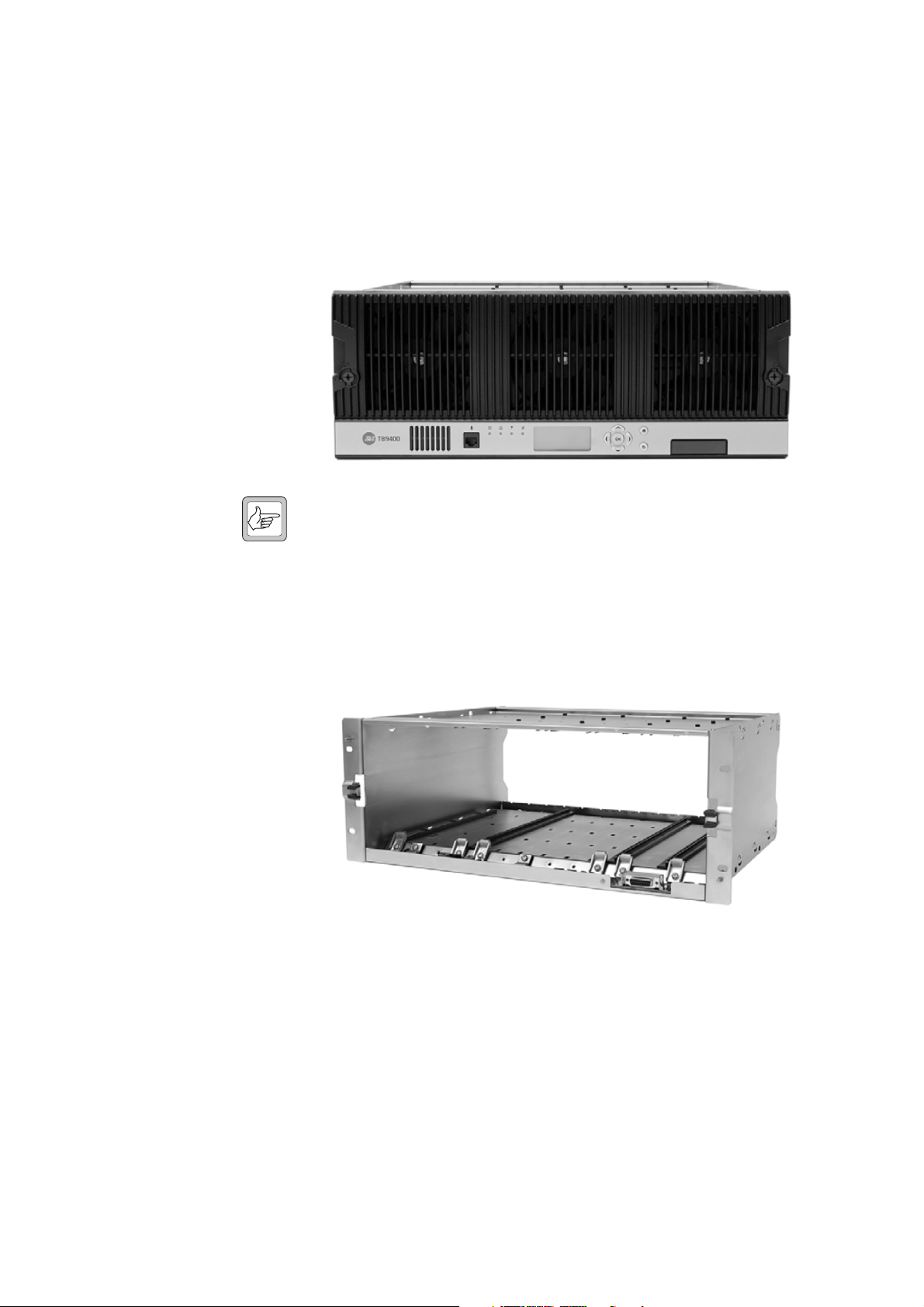
1.2 Modules
The base station consists of a subrack with up to two transmit/receive
channels.
The single PMU (power management unit) supplies and manages power to
the whole subrack (refer to “Theory of Operation” on page 19). One reciter
and one PA (power amplifier) are needed for each transmit/receive channel.
There is also a front panel with user controls and fans. The modules are
interconnected at the front of the subrack. External connections to the
modules are located at the rear.
Modules come in different variants depending, for example, on the RF band
or the supply voltage.
Each module is inserted into the 4 U subrack from the front and is secured
at the front with a metal clamp. Both clamp and module are easily removed
for rapid module replacement. The modules are secured laterally with plastic
guides that clip into the top and bottom of the subrack. These guides can be
easily repositioned to change the configuration of a subrack. The heavier
modules are also secured laterally by metal tabs at the rear of the subrack.
The following provides a brief description of the available modules.
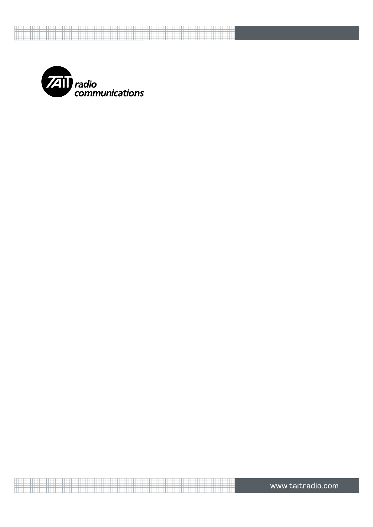
Reciter The reciter module comprises the
receiver, exciter and digital control
circuitry. The reciter provides the
Ethernet interface and system inputs
and outputs.
TB9400 Installation and Operation Manual Description 11
© Tait Electronics Limited September 2011
DRAFT 4
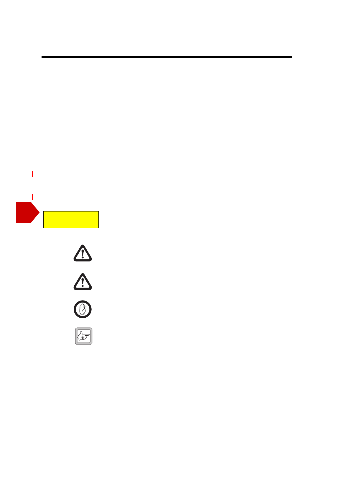
Power Amplifier The PA amplifies the RF output from the reciter and is available in 50 W
and 100 W models.
The 50 W model mounts vertically in the subrack, while the 100 W model
mounts horizontally as it has a wider heatsink. The 100 W PA is also fitted
with an airflow duct.
50 W PA 100 W PA
Both models are designed to operate on the 28 VDC output provided by the
PMU.
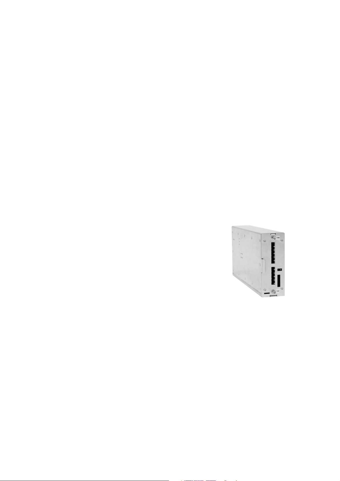
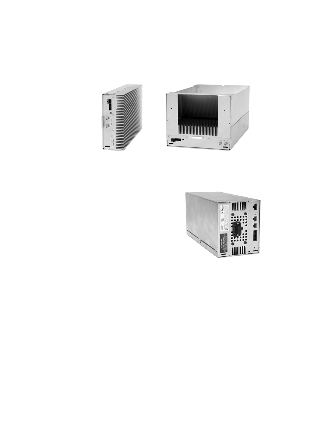
Power
Management Unit
The PMU provides the 28 VDC
power supply for the modules in the
subrack. The input voltage can be AC,
DC or both AC and DC, depending
on the model. The PMU also has an
auxiliary DC output of 13.65 VDC,
27.3 VDC, or 54.6 VDC, depending
on the model.
AC and DC PMU shown
12 Description TB9400 Installation and Operation Manual
© Tait Electronics Limited September 2011
DRAFT 4
Front Panel The front panel is mounted onto the subrack with two quick-release
fasteners. It incorporates the indicator LEDs, four-line LCD display, user
controls and cooling fans.
The indicator LEDS allow some monitoring of the operational status of the
base station. The user controls and display allow the technician to configure
the IP address of each module. Refer to “Front Panel” on page 36 for more
information.
Note The microphone input and speaker are not used in this release of
the TB9400.
Subrack The 4 U subrack is made of passivated steel and is designed to fit into a
standard 19 inch rack or cabinet. The subrack is fitted with an interconnect
board that connects the system control bus and power to the modules and
front panel. The position of a module in the subrack is defined by the socket
on the subrack interconnect board to which the module is connected by the
system control bus.
TB9400 Installation and Operation Manual Description 13
© Tait Electronics Limited September 2011
DRAFT 4
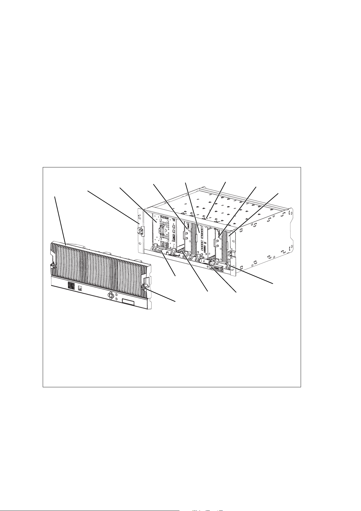
1.3 Mechanical Assembly
This section illustrates the main mechanical components of the base station.
Figure 1.1 below shows the configuration for a typical dual 50 W base
station. The PMU occupies the slot at the left end of the subrack, with the
reciter and PA pairs to the right of it. Each PA is mounted vertically with its
heatsink facing its associated reciter. The PMU and each reciter/PA pair
have their own cooling fans.
The front panel can be easily removed from the subrack by undoing two
quick-release fasteners. Refer to “Replacing Modules” on page 93 for more
details.
Figure 1.1 Mechanical assembly - dual 50 W base station with front panel
b
c
.
g
h
d
e
f
1@
1!
1)
1#
b front panel i reciter 1
c subrack j module retaining clamp
d PMU 1) subrack interconnect board
e PA 2 1! plastic guide rail
f reciter 2 1@ subrack interconnect board retaining clamp
g cable retaining clip 1# front panel fastener
h PA 1
i
j
14 Description TB9400 Installation and Operation Manual
© Tait Electronics Limited September 2011
DRAFT 4
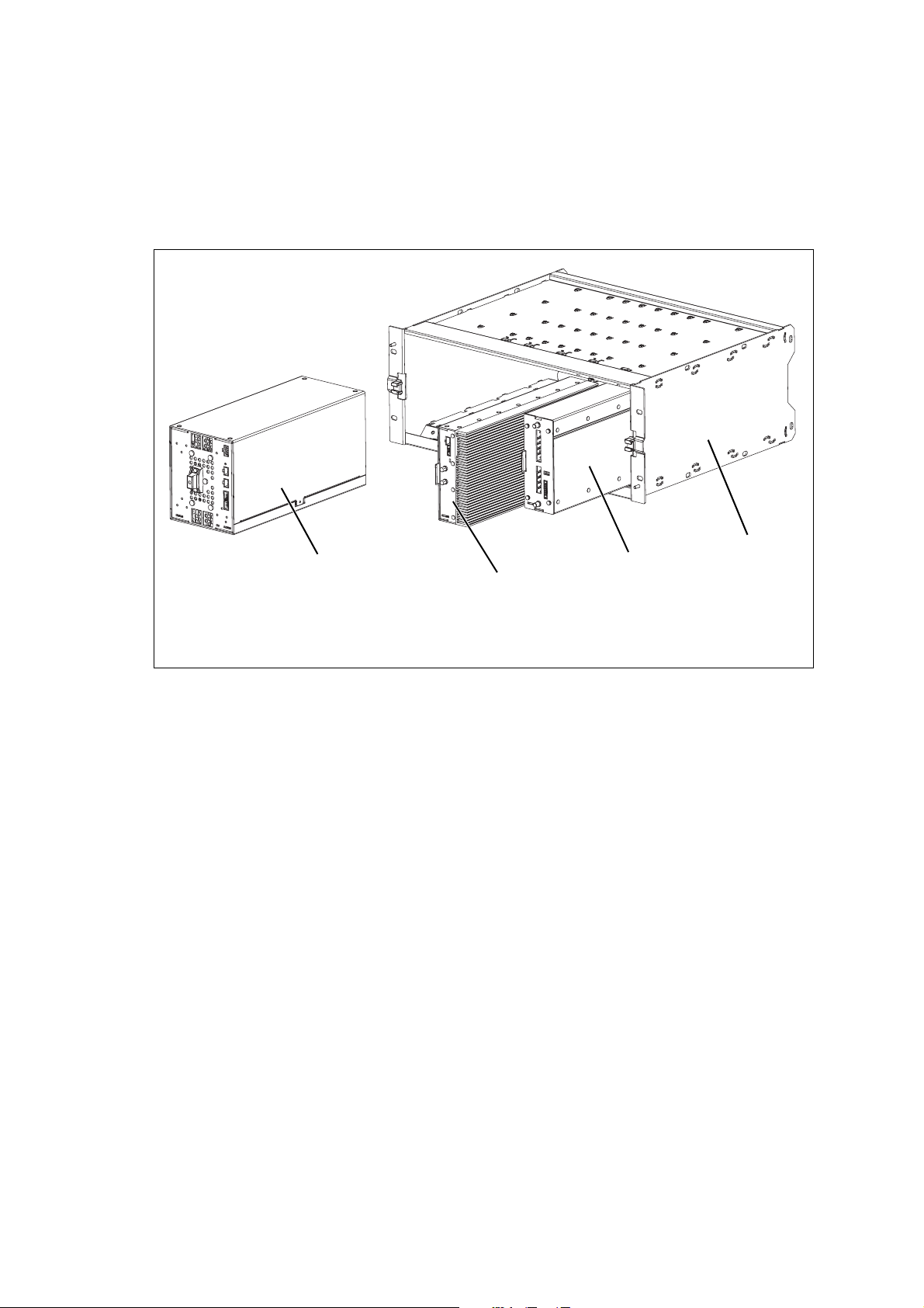
Figure 1.2 below shows the configuration for a typical single 50 W base
station. The PMU occupies its usual slot at the left end of the subrack, with
the reciter and PA pair at the right of the subrack. The PA is mounted
vertically with its heatsink facing the reciter. The PMU and the reciter/PA
pair have their own cooling fans.
Figure 1.2 Mechanical assembly - single 50 W base station
b
c
b PMU d reciter
c 50 W PA e subrack
e
d
TB9400 Installation and Operation Manual Description 15
© Tait Electronics Limited September 2011
DRAFT 4
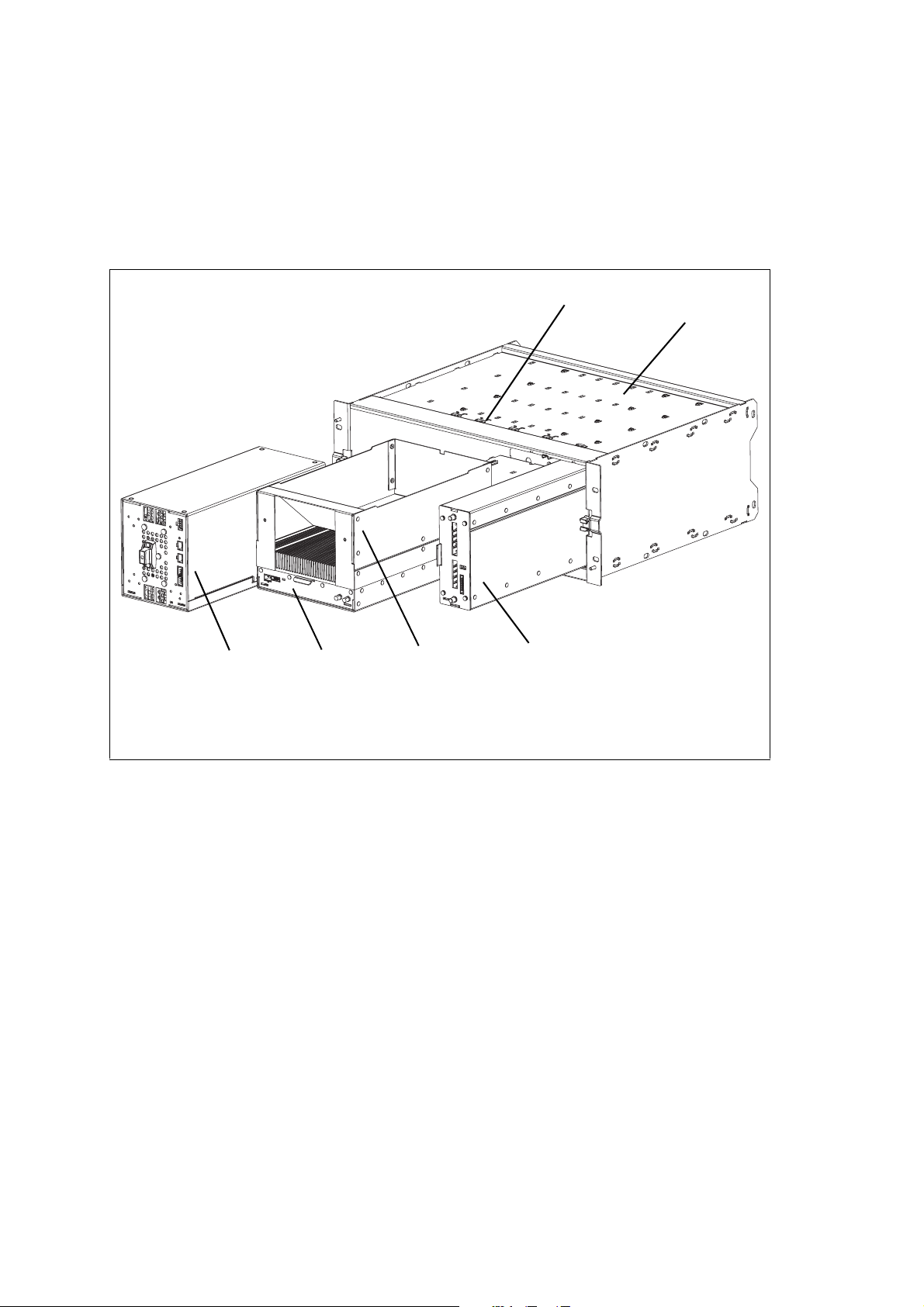
Figure 1.3 below shows the configuration for a typical 100 W base station.
The PMU occupies its usual slot at the left end of the subrack, with the PA
directly beside it. The reciter occupies the slot at the right of the subrack.
Unlike the 50 W PAs, the 100 W PA is mounted horizontally with the
heatsink facing upwards. It is also fitted with an airflow duct to channel the
airflow from the cooling fan through the heatsink fins.
Figure 1.3 Mechanical assembly - single 100 W base station
g
f
b
b PMU e reciter
c PA f subrack
d airflow duct g cable retaining clip
c
d
e
16 Description TB9400 Installation and Operation Manual
© Tait Electronics Limited September 2011

DRAFT 4
1.4 Frequency Bands and Sub-bands
The first release of the base station operates only on K band. Later releases
will support operation on other frequency bands.
Frequency
Identification Frequency Band and Sub-band
K band K4 = 762 MHz to 870 MHz
a. The actual frequency coverage in this band is:
Transmit: 762 MHz to 776 MHz, and 850 MHz to 870 MHz
Receive: 792 MHz to 824 MHz
1.5 Applications
The TB9400 is designed for operation in a TaitNet P25 trunked radio
network. It can operate as a single base station or as part of a channel group
or simulcast channel group, and as a traffic channel or control channel.
In a trunked simulcast network, the transmitters in the channel group are
synchronized and transmit simultaneously on the same frequency. Each
transmitter needs a highly accurate 1 PPS pulse and an external frequency
reference, so that it can time transmissions with the required accuracy. We
also recommend using an NTP server at each site, as this will ensure a
common timestamp in logs across all units in the system.
For more information, refer to the TaitNet P25 System Manual.
a
TB9400 Installation and Operation Manual Description 17
© Tait Electronics Limited September 2011

DRAFT 4
1.6 Licenses
Some operational functions of the base station are controlled by licenses.
These functions will not work unless you purchase the appropriate feature
license and enable the feature set controlled by that license. The feature sets
currently available are listed below.
P25 Common Air
Interface
P25 Trunking
Operation
Networking with
Centralized Voter
Simulcast
Transmitter
Simulcast
Modulation
Allows the base station to go into Online mode. Base stations are always
provided with this license.
Allows a base station to participate in a trunking system. Without this
feature, the base station cannot provide a control or a status connection to a
trunking site controller and it cannot function as a control or traffic channel.
Allows the base station to act as a central voter within its channel group. This
feature also allows voice networking. Only base stations that will centrally
vote (normally the central voter and its backup) need this feature. The other
members of the channel group only need the networking with distributed
voter feature. A standard trunked base station (standalone without fill-in
repeaters or other channel group members) can function as a master or a
failsoft repeater without this license.
This feature is required in base stations that have transmitters and belong to
a simulcast network.
Allows the base station to transmit using the LSM modulation scheme. This
scheme is designed to minimize performance degradation in simulcast
channels caused by delay spread.
Failsoft for P25
Trunking
Allows trunked channels that become isolated from a site controller to
perform simple conventional operation and to interface to a digital dispatch
system. If a trunked channel consists of several base stations in a channel
group, only the central voter (normally the master) needs this license. It is
then able to become the failsoft repeater for that channel group.
Phase 2 Operation
(not yet available)
18 Description TB9400 Installation and Operation Manual
This feature will allow the base station to operate in trunking mode using
two-slot TDMA as defined by the P25 Phase 2 standard.
© Tait Electronics Limited September 2011

DRAFT 4
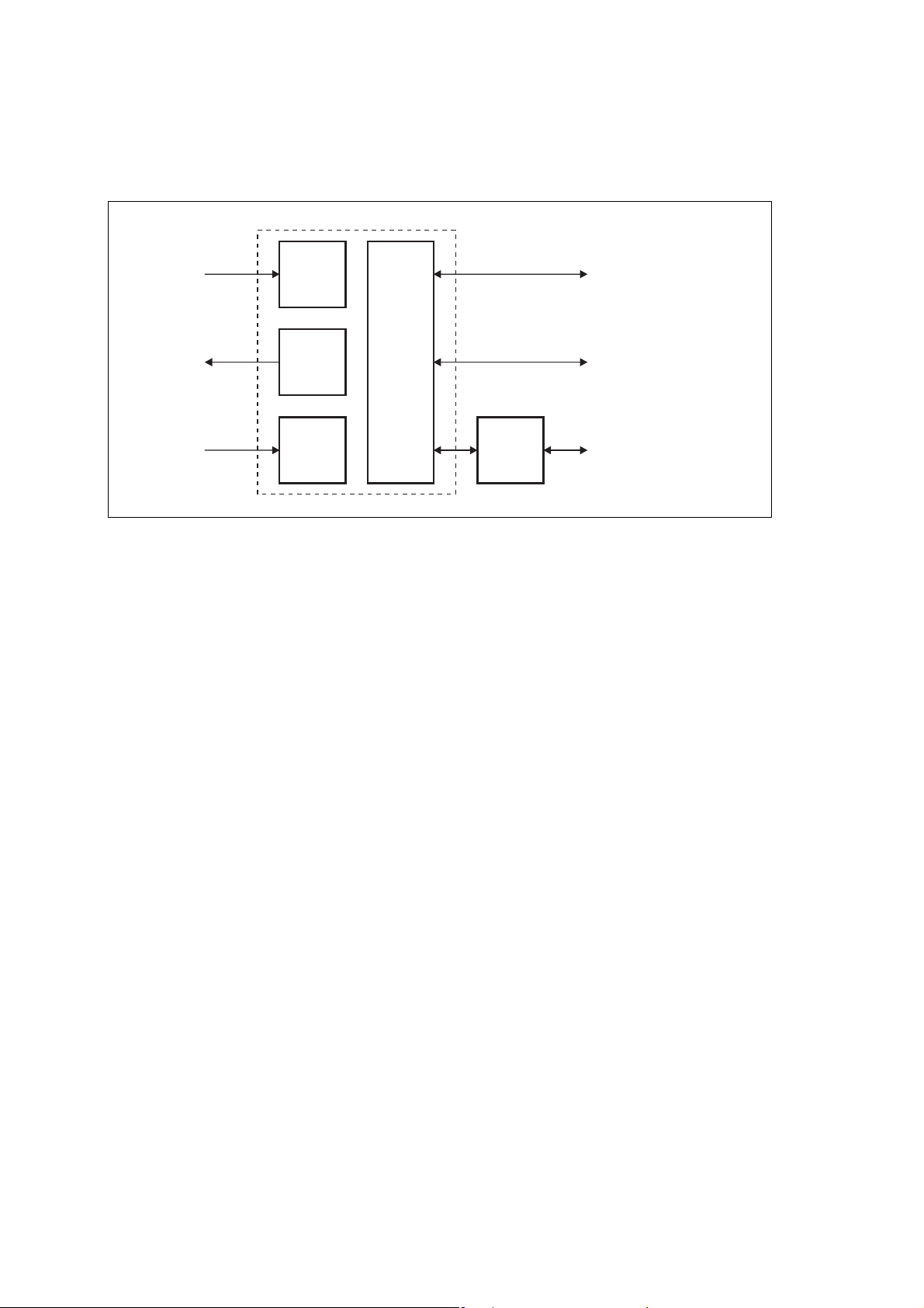
1.7 Theory of Operation
The reciter receives RF signals from its RF input and sends RF from its RF
output to the PA, along with a PA key signal. The PA sends an RF feedback
signal to the reciter for linearization and power control purposes. The reciter
also receives signals from, and sends signals to, the system interface, the
Ethernet interface, and the front panel (see Figure 1.4).
A system control bus interconnects the modules and carries alarm and
control signaling between the reciter and the other modules.
The Ethernet interface carries voice over IP and also allows maintainer
access via a web browser.
Figure 1.4 Base station high-level diagram
AC Input
DC Input
*optional for non-simulcast systems
PMU
28VDC
RF To
Antenna
PA
System Control Bus
RF + PA Key
RF Feedback
RF From
Antenna
1PPS*
Reciter
Front
Panel
External
Reference
Frequency*
System Input
and Output
Ethernet Interface
to Network
TB9400 Installation and Operation Manual Description 19
© Tait Electronics Limited September 2011
DRAFT 4
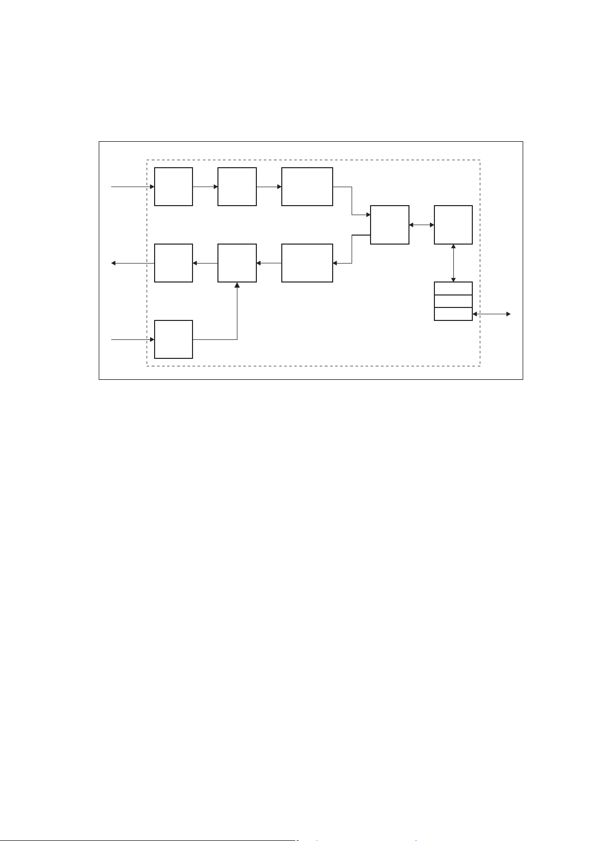
The reciter carries out signal processing and has overall control of the base
station. It has four boards, as shown in Figure 1.5.
Figure 1.5 Reciter boards
RF Input
RF Output
RF Input
(feedback
from PA)
Receiver
Board
Transmit
Forward
Board
Transmit
Reverse
Board
Reciter
Control
Board
Front
Panel
System Input
and Output
Ethernet Interface
to Network
Maintainer Access
The receiver board contains all the receiver circuitry, while the exciter
circuitry is located on the transmit forward board.
The reciter control board converts information between analog and digital
and controls the maintainer’s access via the front panel. It performs the air
interface signal processing for digital P25 mode, gives the base station an
identity as a network element, and provides the physical connections for the
Ethernet and system interfaces.
20 Description TB9400 Installation and Operation Manual
© Tait Electronics Limited September 2011
DRAFT 4
1.7.1 Signal Paths
Figure 1.6 gives an overview of signal paths within the reciter.
Figure 1.6 Reciter signal paths
Receive
RF Interface
ADC
DDC
Demodulator
Transmit
RF Interface
Transmit
RF Interface
(feedback
from PA)
DAC
ADC
Cartesian
Loop
P25
Modem
Modulator
Protocol
Reciter Control Board
Stack
Control
RTP
UDP
IP
Ethernet
Interface
Digital P25 signals from the receive RF interface pass through the digital
receiver and P25 modem to the control software in the RISC processor. The
control software passes the signal through the Ethernet interface to the site
controller, or to the central voter in a simulcast system.
Input to the Ethernet interface can be from the site controller, or from the
central voter in a simulcast system. These inputs are processed by the RISC
and passed through the P25 modem to the transmitter. If the base station is
itself a central voter, this input can also be a received signal, which is voted
on and sent back through the Ethernet interface to the site controller.
1.7.2 Online and Offline Modes
The base station normally operates in Online mode, but you can put it into
Offline mode via its web interface.
Online Mode In Online mode, the base station performs its normal functions.
Offline Mode When you program the base station or run invasive diagnostic tests, the base
station must be in Offline mode. This takes the base station out of service.
However, the front panel is still operational and can be used in the normal
way.
TB9400 Installation and Operation Manual Description 21
© Tait Electronics Limited September 2011
DRAFT 4
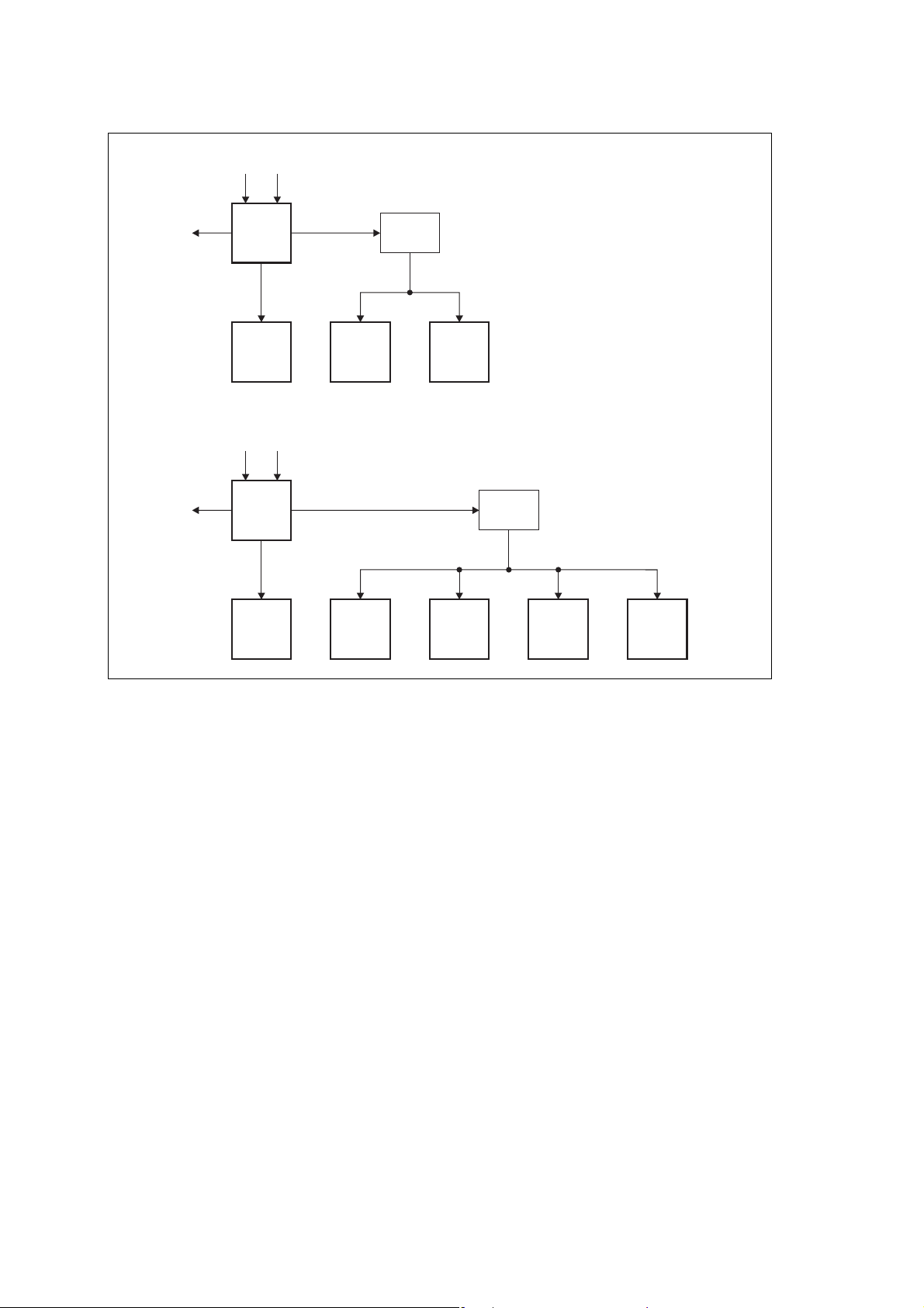
1.7.3 Intermodule Communications
A system control bus and a subrack interconnect board link the modules in
the subrack and carry alarm and control signaling between the reciter and
the other modules, as shown in Figure 1.7.
Figure 1.7 Intermodule communication paths
PMU
Fan
Reciter 1/
PA 1 Fan
User
Controls
Reciter 2/
PA 2 Fan
Front Panel
PMU
2
I C Current
Source
Fan
μP
2
Subrack Interconnect Board
2
I C
Reciter 1
μP
RS-485
PMU Fan
PA 1
μP
RS-485I C
PA Fa n
Fan
Fan
FanFan
PA 2
μP
Reciter 2
RS-485RS-485
μP
22 Description TB9400 Installation and Operation Manual
© Tait Electronics Limited September 2011

DRAFT 4
1.7.4 Power Management and Distribution
The PMU manages the supply of power to ensure uninterrupted operation
of the base station. A range of parameters is monitored and these can trigger
alarms that are sent to the reciter. Alarms can be monitored via the web
interface, and are also recorded in the reciter’s internal log file.
AC to DC
Changeover
When the PMU has an AC and a DC module, the base station can be
powered by either the AC (mains) or the DC (battery) supply. The base
station will default to the AC supply if both supplies are provided. If the AC
supply becomes unavailable, a seamless changeover from the AC to DC
supply takes place, providing that the battery voltage is above the configured
minimum. You can use a web browser to check whether the base station is
running on battery or mains power.
DC Operation When the base station is running off the DC supply and the battery voltage
falls below the configured minimum, the base station will enter battery
protection mode to protect the battery and base station equipment. The
standby power supply card maintains the power to the PMU microprocessor,
while the rest of the PMU is shut down. When the battery voltage rises to
the configured startup setting, power is resumed to the DC supply. Refer to
“PMU Operation on DC Input” on page 25 for more detailed information.
Auxiliary Power
Control
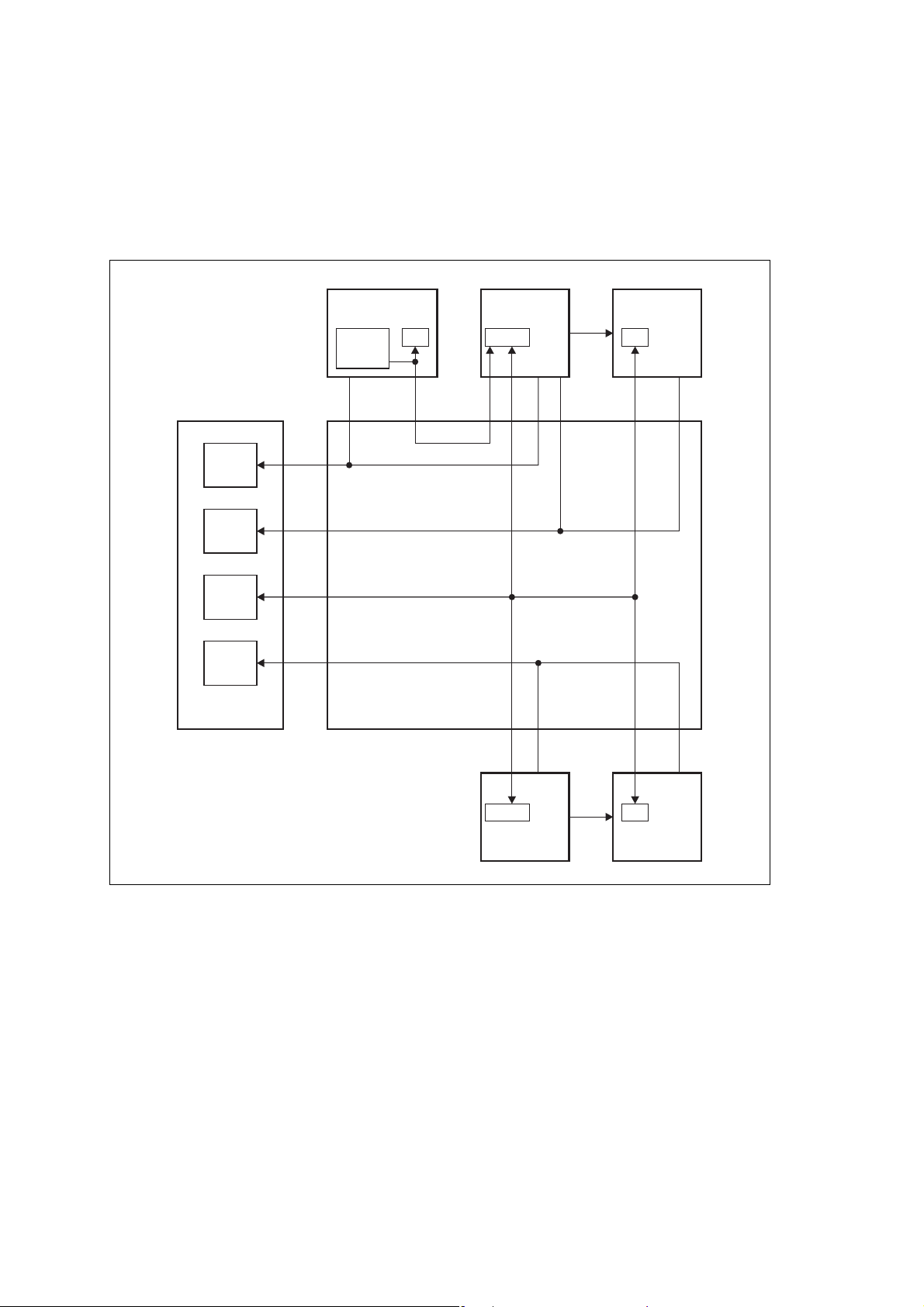
Distribution Figure 1.8 shows how power is distributed to modules in the subrack. The
The output from the auxiliary power supply board can be used to power
other site equipment. The maximum output is 40 W.
28 VDC output from the PMU is fed directly to the 100 W PA and 50 W
PA1, and to the other modules via the subrack interconnect board. Power
to the reciters and front panel is current-limited by self-resetting fuses on the
subrack board.
The AC converter has a series switch which breaks the phase input to the
converter. The DC input, however, has much higher current ratings. Its
switch does not disconnect power from the DC converter itself, but disables
the converter by switching off its control circuitry.
The outputs from both the AC and DC high power converters are added
together and fed to the modules via the high-current outputs. The auxiliary
output is also tapped off this summed output.
TB9400 Installation and Operation Manual Description 23
© Tait Electronics Limited September 2011
DRAFT 4
Figure 1.8 Subrack power distribution for single and dual base stations
Single
Dual
DC AC
Aux. DC 28V
Aux. DC 28V
PMU
28V
PA Reciter
DC AC
PMU
28V
Subrack
Board
Front
Panel
Subrack
Board
PA 1 PA 2 Reciter 1
Reciter 2
Front
Panel
24 Description TB9400 Installation and Operation Manual
© Tait Electronics Limited September 2011

DRAFT 4
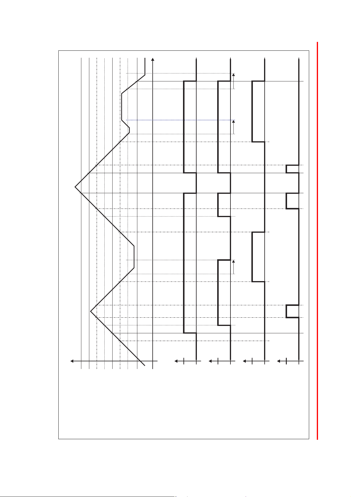
1.7.5 PMU Operation on DC Input
The operation of the PMU on DC input is controlled by three sets of
parameters:
■ user-programmable alarms
■ user-programmable startup and shutdown limits
■ battery protection limits
The voltage range for each of these parameters is provided in Table 1.1 on
page 26. Figure 1.9 on page 27 illustrates how these parameters interact, and
how they control the operation of the PMU over a range of DC input
voltages.
Alarms User-programmable alarms can be set for low or high battery voltage
(Configure > Alarms > Thresholds). The alarms will be triggered when the
set voltage levels are reached. These limits are subject to the tolerances of the
battery protection circuitry, as stated in “Battery Protection (Fail-safe)
Limits” in Table 1.1.
Startup and
Shutdown Limits
Battery Protection
Limits
The user-programmable startup and shutdown limits allow for adjustable
startup and shutdown voltages (Configure > Base Station > Miscellaneous).
These limits can be adjusted for different numbers of battery cells, or for the
particular requirements of the base station operation. Once the limits are
reached, the PMU will shut down. These limits are subject to the tolerances
of the battery protection circuitry, as stated in “Battery Protection (Fail-safe)
Limits” in Table 1.1.
Important It is possible to set the startup voltage of the base station
below the nominal voltage of the battery. Continuing to use
a battery for extended periods when it is below its nominal
voltage will severely shorten its service life. For more infor
mation on battery management, we recommend that you
consult the battery manufacturer.
The battery protection limits are set in hardware at the factory, and cannot
be adjusted by the user. These limits will not be reached under normal
operation conditions, but are provided as “fail-safe” measures to protect the
battery from deep discharge. They also remove the need for low-voltage
disconnect modules.
-
TB9400 Installation and Operation Manual Description 25
© Tait Electronics Limited September 2011

DRAFT 4
Table 1.1 PMU DC voltage limits
Parameter
User-programmable Alarms
Low Battery Voltage
High Battery Voltage
User-programmable Limits
Startup Voltage (after shutdown)
Shutdown Voltage
Battery Protection (Fail-safe) Limits
Startup Voltage
Undervoltage Shutdown
Overvoltage Shutdown
Overvoltage Shutdown Reset
a. The information in this table is extracted from the Specifications Manual. Refer to the latest issue of this manual
for the most up-to-date and complete PMU specifications.
b. Using the base station’s web interface.
c. These limits are subject to the tolerances of the battery protection circuitry.
b
bc
a
Voltage Range
12 V PMU 24 V PMU 48 V PMU
10 V to 14 V
14 V to 17.5 V
10.9 V to 15 V ± 0.3 V
10 V to 13.5 V ± 0.3 V
10.8 V +
9.5 V +
18.1 V +0.3 V
17.1 V +
0.2 V
0.3 V
0.3 V
20 V to 28 V
28 V to 35 V
21.8 V to 30 V ± 0.3 V
20 V to 27 V ± 0.3 V
21.6 V +
19 V +
36.2 V +0.5 V
34.2 V +
0.5 V
0.5 V
0.5 V
40 V to 56 V
56 V to 70 V
43.6 V to 60 V ± 0.3 V
40 V to 54 V ± 0.3 V
43.2 V +
1 V
38 V +
72.4 V +1 V
68.4 V +
1 V
1 V
26 Description TB9400 Installation and Operation Manual
© Tait Electronics Limited September 2011
DRAFT 4
Figure 1.9 PMU alarm thresholds and voltage limits when operating on DC
Time
DC Input Voltage
Overvoltage Shutdown (HW)
Overvoltage Shutdown Reset (HW)
High Battery Voltage Alarm (SW Alarm)
Startup Voltage (SW)
Startup Voltage (HW)
Shutdown Voltage (SW)
Undervoltage Shutdown (HW)
Low Battery Voltage Alarm (SW Alarm)
30s delay 30s delay 30s delay
Run
0V
Hardware Behaviour
Stop
Run
Software Control &
Hardware Combined
Stop
Software Alarm
Off
Active
Software Alarm
(Low Battery Voltage)
Off
Active
(High Battery Voltage)
TB9400 Installation and Operation Manual Description 27
© Tait Electronics Limited September 2011

DRAFT 4
1.7.6 Front Panel Fans
The front panel is equipped with three fans. One fan is for the PMU and
the other two are for the reciter/PA pairs in a 50 W base station, or for the
PA and reciter in a 100 W base station. Front panel fans do not operate
continuously but are switched on and off as needed by the reciter firmware.
Each reciter controls the fan it shares with its PA, and reciter 1 also controls
the PMU fan. Under certain conditions the PMU and each PA can override
the reciter and assume control of its own fan.
Front panel fans are 3-wire fans (power, ground, and rotation detect). The
reciter can monitor whether the fans are rotating and generate an alarm if
the fan fails.
The fans turn on for a few seconds when the base station is powered up, and
also after the front panel is refitted to a base station which is powered up.
Configuring Fan
Control
The operation of the PA fan is configurable via the web interface; you can
specify the threshold temperature at which the fan will be turned on, and
set the fan to operate only when the PA is transmitting.
The PMU fan has fixed on/off thresholds and a defined set of duty cycles
based on the PMU temperature, as described in the following table:
PMU Temperature Fan Duty Cycle
<149 °F (65 °C) Increases as the load on the PMU
increases
149-167 °F (65-75 °C) On for two minutes, off for one minute
>167 °F (75 °C) Always on
28 Description TB9400 Installation and Operation Manual
© Tait Electronics Limited September 2011

DRAFT 4
2 General Safety and Regulatory
Information
This chapter provides general information on safety precautions for
operating the base station.
2.1 Personal Safety
2.1.1 Unpacking and Moving the Equipment
To prevent personal injury and equipment damage, we recommend that two
people unpack and move the equipment.
Caution A subrack complete with modules can weigh up to
2.1.2 Lethal Voltages
Warning!! The PMU contains voltages that may be lethal.
The equipment must be installed so that the rear of the PMU is located in
a service access area which is accessible only by qualified personnel. The
PMU must be connected to the mains supply source by qualified personnel
in accordance with local and national regulations.
55 lb (25 kg), or up to 62 lb (28 kg) complete with
packaging. We recommend that you have another
person help you unpack and move the equipment.
The TBAA03-16 carrying handles will make it easier
to move the equipment once it has been unpacked.
If necessary, remove the modules from the subrack
before moving it (refer to “Replacing Modules” on
page 93). In all cases follow safe lifting practices.
Refer to the ratings label on the rear of the
module.
Disconnect the mains IEC connector and wait for five minutes for
the internal voltages to self-discharge before dismantling. The AC
power on/off switch does not isolate the PMU from the mains. It
breaks only the phase circuit, not the neutral.
The PMU should be serviced only by qualified technicians. There are no
user-replaceable parts inside. If the PMU is damaged and does not function
TB9400 Installation and Operation Manual General Safety and Regulatory Information 29 © Tait Electronics Limited September 2011

DRAFT 4
properly, stop the module safely and contact your regional Ta it office
immediately.
All servicing should be carried out only when the PMU is powered through
a mains isolating transformer of sufficient rating.
2.1.3 AC Power Connection
English (en) The PMU must be connected to a grounded mains
Norsk (no) Apparatet må tilkoples jordet stikkontakt.
Suomi (fi) Laite on liitettävä suojamaadoitus-koskettimilla
Svenska (sv) Apparaten skall anslutas till jordat uttag.
socket-outlet.
varustettuun pistorasiaan.
2.1.4 Explosive Environments
Warning!! Do not operate the equipment near electrical
blasting caps or in an explosive atmosphere.
Operating the equipment in these environments
is a definite safety hazard.
2.1.5 Proximity to RF Transmissions
Do not operate the transmitter when someone is standing within 3 ft (90 cm)
of the antenna. Do not operate the transmitter unless you have checked that
all RF connectors are secure.
2.1.6 High Temperatures
Take care when handling a PMU or PA which has been operating recently.
Under extreme operating conditions (+ 140° F [+60° C] ambient air
temperature) or high duty cycles, the external surfaces of the PMU and PA
can reach temperatures of up to + 176° F (+ 80° C).
2.1.7 LED Safety (EN 60825-1)
This equipment contains Class 1 LED Products.
30 General Safety and Regulatory Information TB9400 Installation and Operation Manual
© Tait Electronics Limited September 2011

DRAFT 4
2.2 Equipment Safety
2.2.1 Installation and Servicing Personnel
The equipment should be installed and serviced only by qualified personnel.
2.2.2 Preventing Damage to the PA
The base station has been designed to operate safely under a wide range of
antenna loading conditions. Transmitting into a low VSWR will maximize
the power delivered to the antenna.
Important Do not remove the load from the PA while it is
transmitting.
Load transients (switching or removing the load) or atmospheric
disturbances (for example rain static and electrical storms) can damage the
PA output stage. See “Connecting RF” on page 84 for recommendations.
2.2.3 ESD Precautions
Important This equipment contains devices which are susceptible to
We recommend you purchase an antistatic bench kit from a reputable
manufacturer and install and test it according to the manufacturer’s
instructions. Figure 2.1 shows a typical antistatic bench set-up.
You can obtain further information on antistatic precautions and the dangers
of electrostatic discharge (ESD) from standards such as ANSI/ESD
S20.20-1999 or BS EN 100015-4 1994.
Figure 2.1 Typical antistatic bench set-up
common point ground
(building ground or
mains ground)
dissipative rubber
bench mat
damage from static charges. You must handle these devices
carefully and according to the procedures described in the
manufacturers’ data books.
conductive wrist strap
TB9400 Installation and Operation Manual General Safety and Regulatory Information 31
© Tait Electronics Limited September 2011

DRAFT 4
2.2.4 Anti-tampering Devices
All network elements should be physically secured, where possible. This
includes the use of locked cabinets and the use of seals on connectors.
All network and audio connectors should be sealed with the stick-on type
of seal. The purpose of the seals is to detect unauthorized tampering. The
seal should reveal if any of the connectors have been unplugged or if any
unauthorized equipment has been plugged in.
The seals must be difficult to remove without breaking, and must bridge
between the cable and equipment side (plug and socket) of the connection.
Seals must cover any unused network or audio sockets. This includes the
Ethernet connector on the rear panel, any spare switch ports, and the
console port on the router and switch.
The seals must be difficult to reproduce. A sticker initialed or signed by the
technician should satisfy this.
Seals must be replaced if they need to be disturbed during maintenance.
2.3 Environmental Conditions
2.3.1 Operating Temperature Range
The operating temperature range of the equipment is – 22°F to + 140°F
(– 30°C to + 60°C) ambient temperature. Ambient temperature is defined as
the temperature of the air at the intake to the cooling fans.
2.3.2 Humidity
The humidity should not exceed 95% relative humidity through the
specified operating temperature range.
2.3.3 Dust and Dirt
For uncontrolled environments, the level of airborne particulates must not
exceed 100 µg/m
3
.
32 General Safety and Regulatory Information TB9400 Installation and Operation Manual
© Tait Electronics Limited September 2011

DRAFT 4
2.4 Regulatory Information
2.4.1 Distress Frequencies
The 406 to 406.1 MHz frequency range is reserved worldwide for use by
Distress Beacons. Do not program transmitters to operate in this frequency
range.
2.4.2 FCC Compliance
This equipment complies with:
■ CFR Title 47 Part 15 Class B (except PMU):
Radiated and conducted emissions, and electromagnetic susceptibility
specifications of the Federal Communications Commission (FCC) rules
for the United States.
Operation is subject to the following two conditions:
a. This device may not cause harmful interference, and
b. This device must accept any interference received, including
interference that may cause undesired operation.
■ CFR Title 47 Part 15 Class A (PMU only):
Radiated and conducted emissions, and electromagnetic susceptibility
specifications of the Federal Communications Commission (FCC) rules
for the United States.
Operation is subject to the following two conditions:
a. This device may not cause harmful interference, and
b. This device must accept any interference received, including
interference that may cause undesired operation.
2.4.3 Unauthorized Modifications
Any modifications you make to this equipment which are not authorized by
Tait Electronics Limited may invalidate your compliance authority’s approval
to operate the equipment.
TB9400 Installation and Operation Manual General Safety and Regulatory Information 33
© Tait Electronics Limited September 2011

DRAFT 4
2.4.4 Health, Safety and Electromagnetic Compatibility in Europe
In the European Community, radio and telecommunications equipment is
regulated by Directive 1999/5/EC, also known as Radio and
Telecommunications Terminal Equipment (R&TTE) directive. The
requirements of this directive include protection of health and safety of users,
as well as electromagnetic compatibility.
Intended Purpose of
Product
Declaration of
Conformity
This product is a radio transceiver. It is intended for radio communications
in the Private Mobile Radio (PMR) or Public Access Mobile Radio
(PAMR) services, to be used in all member states of the European Union
(EU) and states within the European Economic Area (EEA).
can be programmed to transmit on frequencies that are not harmonized
throughout the EU/EEA, and will require a licence to operate in each
member state.
You can download the formal Declaration of Conformity from
http://eudocs.taitradio.com/. You can also obtain a signed and dated paper
copy of the Declaration of Conformity from Tait Electronics Limited.
This product
34 General Safety and Regulatory Information TB9400 Installation and Operation Manual
© Tait Electronics Limited September 2011

DRAFT 4
3 Operation
This section describes the user controls and indicator LEDs on the front
panel and on the base station modules.
TB9400 Installation and Operation Manual Operation 35
© Tait Electronics Limited September 2011
DRAFT 4
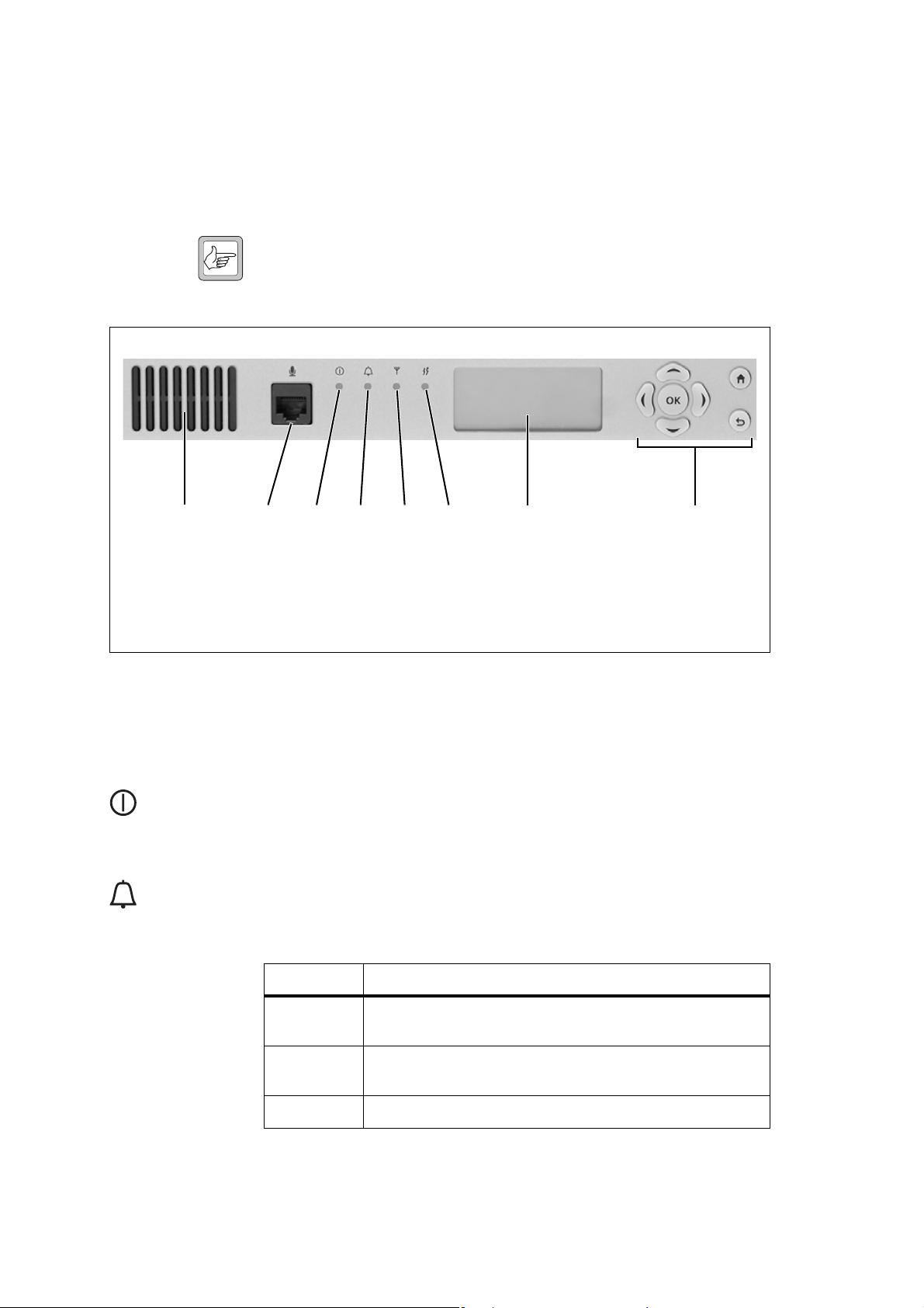
3.1 Front Panel
The user controls and indicator LEDs on the front panel are shown in
Figure 3.1. They allow some manual control over the base station and
monitoring of its operational status.
Note If there is more that one reciter in a subrack, inputs from all recit-
ers are summed to drive the front panel LEDs.
Figure 3.1 Operating controls on the control panel
b c
d
e
b
c
de
gi
f
h
b speaker f receive LED
c microphone connector g transmit LED
d power LED h keypad
e alarm LED i display
Speaker and
Microphone
Connector
Power LED The green power LED is lit when power is supplied to the subrack.
Alarm LED The red alarm LED will flash at a rate of 2 to 5 Hz when an alarm has been
The speaker and microphone connector are not used in this release of the
base station.
generated by any of the base station modules. It will continue to flash until
the alarm is canceled or the fault is fixed. Note that only those alarms which
are enabled using the web interface will cause this LED to flash.
LED Description
On (steady) The base station is in Offline mode (regardless of the presence of
any fault).
Flashing The base station is in Online mode, and one or more faults are
present.
Off The base station is in Online mode, and no faults are present.
36 Operation TB9400 Installation and Operation Manual
© Tait Electronics Limited September 2011

DRAFT 4
Receive LED The amber receive LED indicates whether the base station is receiving a
f
Transmit LED The amber transmit LED is lit while the transmitter is transmitting.
g
Keypad The keypad is used to navigate the base station’s menus, enter text, and to
h
valid RF signal.
LED Description
On (steady) The base station is receiving a valid RF signal.
Off The base station is not receiving a valid RF signal.
adjust the contrast of the display. The complete list of menu items is provided
in “Menu Map” on page 39.
If required, the keypad can be disabled in the web interface to prevent access
to the base station via the front panel menus (see “Disabling the Front Panel
Keypad” on page 60).
Key Name Function
left and right
arrow keys
scroll keys
OK
OK
home
return
■ Move the cursor to the left or right when entering text. Moving the cursor
beyond the end of a line will return it to the other end of the same line.
■ Decrease or increase the contrast in the Display Contrast screen.
■ Scroll up and down through a list of menu items.
■ Scroll up and down through the list of available characters when entering
text.
■ Increase or decrease the contrast in the Display Contrast screen.
■ Selects the highlighted menu item.
■ Confirms any adjustments made and exits to the previous menu.
■ When setting the IP address, moves the cursor down one line. When all
the IP addresses are confirmed, exits to the previous menu.
■ Returns to the idle screen from any other menu.
■ Returns to the previous menu.
■ Moves the cursor up one line in the IP address screen. When the top line is
reached, pressing again returns to the previous menu.
Note Unlike a computer keyboard, the keys do not auto-repeat. Each
action requires a separate key-press.
TB9400 Installation and Operation Manual Operation 37
© Tait Electronics Limited September 2011

DRAFT 4
Display The display is used in conjunction with the keypad to access the base
i
station’s menus. It allows the technician to configure the IP address of each
reciter (refer to “Setting the IP Address” on page 48), and to set the contrast
of the display (see below).
After the base station is powered up, the display shows “Please wait . . .” while
the base station is starting up, followed by the idle screen when the start-up
process is complete. If the front panel loses communication with reciter 1,
the display also shows “Please wait . . .”, and the alarm LED flashes. If the base
station is activating new firmware, the display is blank and the power LED
flashes. The idle screen shows four lines of user-defined text, which can be
entered via the web interface (Identity > Identity > Base Station Identity).
From the idle screen press an ar row key, a scroll key or OK to go to the base
station menu. The display returns to the idle screen from any other screen
30 seconds after the last key press. Press any key to turn on the backlight.
The backlight turns off 30 seconds after the last key press.
Note If the keypad has been disabled, pressing an arrow key, a scroll key
or OK will cause the display to show “Keypad Disabled”.
Set the display contrast as follows:
1. From the base station menu select Modules > Front Panel > Contrast.
2. To increase the contrast, press the right arrow or scroll up key. To
decrease the contrast, press the left arrow or scroll down key.
3. When the contrast is set to the required level, press OK to save the
changes and exit the menu.
38 Operation TB9400 Installation and Operation Manual
© Tait Electronics Limited September 2011

DRAFT 4
Menu Map The menu map below shows the menu items available in this release of the
base station.
Note The menu map shown is for a single base station. The menu items
available in your base station will depend on the modules present
in the subrack.
Idle Screen
Base Station
Modules
Modules
Reciter 1
Reciter 2
Front Panel
Reciter 1
View Reciter 1 Address
Edit Reciter 1 Address
Front Panel
Contrast
View Reciter 1 Address
IP: 172.025. 198.043
MASK: 255.255. 000.000
GW: 172.025. 002. 251
Edit Reciter 1 Address
IP: 172.025. 198.043
1
MASK: 255.255. 000.000
GW: 172.025. 002. 251
Contrast
TB9400 Installation and Operation Manual Operation 39
© Tait Electronics Limited September 2011

DRAFT 4
3.2 Module Indicator LEDs and Switches
Additional status information is displayed by LEDs in individual modules.
The PMU also has switches that let you turn the AC and DC modules off.
3.2.1 Reciter
Front View The indicator LEDs on the front of the reciter are visible through a slot in
its front panel.
Figure 3.2 Indicator LEDs on the front of the reciter
b indicator LEDs
b
These LEDs provide the following information about the state of the reciter:
■ steady green - the reciter is powered up
■ flashing red - one or more alarms have been generated; you can use the
web interface to find out more details about the alarms.
40 Operation TB9400 Installation and Operation Manual
© Tait Electronics Limited September 2011

DRAFT 4
Rear View The indicator LEDs on the rear of the reciter are on the Ethernet connector.
Figure 3.3 Indicator LEDs on the rear of the reciter
b
b indicator LEDs
These LEDs provide the following information about the state of the reciter:
■ steady amber - the Ethernet interface is connected
■ flashing green - data is being transmitted across the Ethernet interface.
TB9400 Installation and Operation Manual Operation 41
© Tait Electronics Limited September 2011

DRAFT 4
3.2.2 PA
The indicator LEDs on the PA are visible through a slot in its front panel.
Figure 3.4 Indicator LEDs on the PA
50 W PA 100 W PA
b
b indicator LEDs
Indicator LEDs These LEDs provide the following information about the state of the PA:
■ steady green - the PA is powered up
■ flashing green - the PA has no application firmware loaded or activated;
you can use the web interface to download or activate the firmware; also
see “Preparing to Download Firmware” on page 61
■ flashing red - one or more alarms have been generated; you can use the
web interface to find out more details about the alarms.
Note The alarm LED will flash whenever an alarm is generated,
whether or not this alarm has been disabled via the web interface.
42 Operation TB9400 Installation and Operation Manual
© Tait Electronics Limited September 2011

DRAFT 4
3.2.3 PMU
The only controls on the PMU are the on/off switches on the rear panel for
the AC and DC modules, and the indicator LEDs visible through a slot in
its front panel.
Figure 3.5 Operating controls on the PMU
rear view
front view
bc
b AC module on/off switch d indicator LEDs
c DC module on/off switch
Warning!! The AC and DC module on/off switches do not
totally isolate the internal circuitry of the PMU
from the AC or DC power supplies. You must
disconnect the AC and DC supplies from the
PMU before dismantling or carrying out any
maintenance. Refer to the service manual for
the correct servicing procedures.
AC Module On/Off
Switch
This switch turns the AC input to the PMU on and off. Note that this
switch breaks only the phase circuit, not the neutral.
Note On switches fitted to PMUs up to November 2008, the red button
is “in” when on, and “out” when off. On switches fitted from
November 2008 onwards, the red button remains “out” whether
on or off.
d
TB9400 Installation and Operation Manual Operation 43
© Tait Electronics Limited September 2011

DRAFT 4
DC Module On/Off
Switch
This switch turns the DC output from the PMU on and off. Note that this
switch does not disconnect power from the DC converter itself. It disables
the converter by switching off its control circuitry. Even when the DC
converter is off, the DC input is still connected to its power circuitry.
The switch is recessed to prevent the DC module being accidentally
switched off, thus disabling the battery back-up supply.
Indicator LEDs These LEDs provide the following information about the state of the PMU:
■ steady green - the PMU is powered up
■ flashing green - the PMU has no application firmware loaded or
activated; you can use the web interface to download or activate the
firmware; also see “Preparing to Download Firmware” on page 61
■ flashing red - one or more alarms have been generated; you can use the
web interface to find out more details about the alarms.
Note The alarm LED will flash whenever an alarm is generated,
whether or not this alarm has been disabled via the web interface.
44 Operation TB9400 Installation and Operation Manual
© Tait Electronics Limited September 2011

DRAFT 4
4 Working with Base Stations from Your
PC
The normal web browser on your PC provides a window into the TB9400
base station. Use it to connect to the base station so that you can monitor,
configure, diagnose, and calibrate it (if required).
This section describes the following:
■ Connecting to the base station, including initially setting things up.
■ Wo r k i n g w i t h base station web pages.
■ Carrying out basic tasks.
This section provides an overview of some aspects of the web interface.
Refer to the Help for detailed instructions.
TB9400 Installation and Operation Manual Working with Base Stations from Your PC 45 © Tait Electronics Limited September 2011

DRAFT 4
4.1 PC Recommendations
We recommend the following PC hardware and software for connecting to
a TB9400 base station:
■ SVGA Monitor (1024 x 768 minimum).
■ Network connection.
■ Mozilla Firefox version 3.6 and later, Microsoft Internet Explorer
version 8 and later.
Note We h a ve t e s t e d t h e base station with Firefox 3.6 and Internet
Explorer 8. If you encounter problems with your web browser,
change to one of these browsers.
4.2 Connecting Your PC to the Base Station
You connect to a base station using your web browser. Using multiple
browser windows or tabs, you can view more than one base station and more
than one page of any base station at once. Base stations have a web-based
interface that provides the pages you view. Up to five users may be logged
in to a base station at once.
The base station has three different user access levels: Administrator,
Maintainer, and Guest. Passwords can be defined for the Administrator and
Maintainer levels. This is don e us in g th e base station’s web interface (Tools >
Tools > User Administration). Refer to the Help for more information on
setting user access levels.
46 Working with Base Stations from Your PC TB9400 Installation and Operation Manual
© Tait Electronics Limited September 2011

?
?
DRAFT 4
4.2.1 Logging In
1. Enter the base station’s URL into your browser: the default address is
Verify default address.
Note If access to this menu on the front panel has been disabled, you can
2. A security warning appears when you connect for the first time.
3. The login screen appears.
https://192.168.1.2
find out the base station’s IP address, on the front panel select Modules > Reciter 1 (or 2) > View Reciter 1 (or 2) Address. To set the
IP address, refer to “Setting the IP Address” on page 48.
find out the IP address by .....how??
Proceed anyway (refer to “Responding to Security Warnings” on
page 49).
(note the use of a secure-socket connection). To
?
?
4. Enter your user name and password. When connecting for the first
time, enter the user name “admin” and password “tbc_admin”.
5. Click Login.
TB9400 Installation and Operation Manual Working with Base Stations from Your PC 47
© Tait Electronics Limited September 2011

DRAFT 4
4.2.2 Setting the IP Address
Before the base station is installed on site, you need to provide it with its
proper IP address. Make sure that you do not lose this address. A quick way
to set the base station’s IP address is to use the front panel, as described
below.
Note If access to this menu on the front panel has been disabled, log in
to the base station and set the IP address using the web interface
(Identity > Identity > Network Identity).
1. Use the front panel display to enter the IP address, subnet mask and
gateway specified for this base station by the IP addressing plan for the
network. From the base station menu select Modules > Reciter 1
(or 2) > Edit Reciter 1 (or 2) Address. If the idle screen is showing,
press an arrow key, a scroll key or OK to clear it.
Important In this screen each octet in the address lines has provision
for three characters. If an octet in the address has less than
three characters, enter one or two leading zeroes so that
each position is filled, even though the zeroes are not part
of the address. For example, enter 172.25.506.47 as
172.025.506.047. Leading zeroes are removed when the
address is programmed into the base station.
2. Set each address as described below. Use the left and right arrow keys
to move the cursor across each line in the Addresses screen. Use the
scroll keys to scroll through the available numbers for each position in
a line.
a. Set the IP address and press OK. This moves the cursor to the next
line. To move the cursor back to the previous line, press the return
key.
b. Set the Mask address and press OK.
c. Set the Gateway address and press OK.
d. The display shows “Setting Reciter 1 (or 2) address Please wait...”
while the base station confirms that the addresses are correct.
When this process has finished, the display will show
“
SUCCEEDED” or “FAILED” as appropriate. Press OK to return to
the previous menu.
3. If the process failed, try entering the address again. It it still fails, try
the following:
■ enter the address through the web interface
■ check that the IP address you are trying to enter is not already in
use by another device on the same subnet.
48 Working with Base Stations from Your PC TB9400 Installation and Operation Manual
© Tait Electronics Limited September 2011

DRAFT 4
4.2.3 Responding to Security Warnings
When your browser connects to a TB9400 for the first time, it raises a
security warning. Normally, secure websites have a security certificate issued
by a trusted Certification Authority. This is to foil attempts by rogue
websites to pretend to be something they are not. Obtaining such certificates
is impractical for each installed TB9400, so a self-signed certificate is created
when the reciter’s firmware is installed.
Your browser raises a security warning because the security certificate was
not issued by a trusted Certification Authority. The browser has a way of
letting you override or bypass the security warning. In Internet Explorer,
you install a certificate, in Mozilla Firefox you add an exception, and in
Google Chrome you elect to proceed anyway.
You can be confident that you are not connecting to a rogue website
pretending to be your TB9400, so follow the procedure below to tell the
browser that the security certificate is OK. The browser then stores the
security certificate and will not raise a warning on subsequent connections,
unless the IP address of the TB9400 changes or you use a different URL
such as https://127.0.0.1. For more information, refer to
http://support.microsoft.com/kb/931850 (Internet Explorer) or search for
“security certificate” in your browser’s Help.
Firefox 1. When the message “This Connection is Untrusted” appears, click
I Understand the Risks.
2. Click Add Exception.
3. The Location field includes details specific to your TB9400. Without
changing the default values, click Confirm Security Exception.
Internet Explorer 1. Click Continue to this website (not recommended).
2. Click Certificate Error.
3. Click View certificates. The Certificate dialog box, General tab is
displayed.
4. Click Install Certificate and then follow the Certificate Import
Wizard to install the certificate. Proceed to the end without changing
the default values. When the Security Warning window appears, click
Yes.
TB9400 Installation and Operation Manual Working with Base Stations from Your PC 49
© Tait Electronics Limited September 2011

DRAFT 4
4.2.4 Connecting a Networked PC to a Base Station
You may want to temporarily disconnect a networked PC from its LAN in
order to be able to establish a direct connection with the base station. A
physical connection is needed as well as an alternate (Windows 7, Windows
Vista, Windows XP) or temporary (Windows 2000) IP address and subnet
mask.
Windows 7 or
Windows Vista
1. Remove the local area Ethernet connection and connect an Ethernet
patch cable between the PC and the base station. You can use either
a straight through or crossover Ethernet patch cable with the current
base station firmware.
2. Navigate to Control Panel > Network and Internet > Network and
Sharing Center.
3. Click View status.
4. In the Local Area Connection Status dialog box, click Properties.
5. In the Local Area Connection Properties dialog box, click Internet
Protocol Version 4 (TCP/IPv4), and then click Properties.
6. Click Alternate Configuration.
7. Select the User configured option, and then enter a number that is on
the same subnet as the base station. For example, if the TB9400 has
IP 192.168.1.2, enter 192.168.1.1 for the PC.
8. Enter a suitable subnet mask, for example 255.255.255.0.
The web browser should now be able to connect to any physically
connected base station that is on the same subnet.
9. Once the web browser session is finished, re-connect the local area
network cable to the PC. The PC then uses its normal TCP/IP
properties.
Windows XP
Professional
50 Working with Base Stations from Your PC TB9400 Installation and Operation Manual
1. Remove the local area Ethernet connection and connect an Ethernet
patch cable between the PC and the base station. You can use either
a straight through or crossover Ethernet patch cable with the current
base station firmware.
2. Click Start > Settings > Control Panel.
3. Double-click Network Connections.
4. Double-click the Local Area Network icon.
5. Click Properties.
6. Click Internet Protocol (TCP/IP), and then click Properties.
7. Click Alternate Configuration.
© Tait Electronics Limited September 2011

DRAFT 4
8. Select the User configured option, and then enter a number that is on
the same subnet as the base station. For example, if the TB9400 has
IP 192.168.1.2, enter 192.168.1.1 for the PC.
9. Enter a suitable subnet mask, for example 255.255.255.0.
The web browser should now be able to connect to any physically
connected base station that is on the same subnet.
10. Once the web browser session is finished, re-connect the local area
network cable to the PC. The PC then uses its normal TCP/IP
properties.
Windows 2000 1. Remove the local area Ethernet connection and connect an Ethernet
patch cable between the PC and the base station. You can use either
a straight through or crossover Ethernet patch cable with the current
base station firmware.
2. Select Start > Settings > Network and Dialup Connections.
3. Double-click the Local Area Connection icon.
4. Click Properties.
5. Click Internet Protocol (TCP/IP), and then click Properties.
6. Note the current settings so that you can restore them later.
7. Select Use the following IP address, and then enter a number that
is on the same subnet as the base station. For example, if the base
station has IP 192.168.1.2, enter 192.168.1.1 for the PC.
8. Enter a suitable subnet mask, for example 255.255.255.0.
The web browser should now be able to connect to the base station.
9. When you have finished the web browser session, re-connect the
local area network cable to the PC and then restore the original PC
configuration. When you close the Network connection dialog box,
the restored configuration is applied.
4.2.5 Troubleshooting Connection Problems
If the attempt to connect to a base station failed, consider these possible
causes.
1. Your PC is part of your organization’s LAN and does not belong to
the same subnet as the base station. Give the PC a suitable IP address
and subnet mask as described in “Connecting a Networked PC to a
Base Station” on page 50.
2. You are attempting to connect to the wrong IP address. Check that
the IP address is correct.
TB9400 Installation and Operation Manual Working with Base Stations from Your PC 51
© Tait Electronics Limited September 2011

?
DRAFT 4
Note You can quickly check the base station’s IP address via the front
panel, as long as access to this menu has not been disabled.
3. The link to the base station is down. Use ping to check.
4. You may have to bypass the proxy in your organization’s LAN to
access the TaitNet P25 Network. Ask your system administrator to
give you access.
4.2.6 Finding a Lost or Forgotten IP Address
What do you do if access
to this front panel menu
has been blocked via the
web interface?
Use the following procedure if an IP address has been lost or forgotten.
1. Mount the reciter in a TB9400 subrack and fit the front panel. Power
up the subrack.
2. On the front panel display select Modules > Reciter 1 (or 2) > View
Reciter 1 (or 2) Address.
52 Working with Base Stations from Your PC TB9400 Installation and Operation Manual
© Tait Electronics Limited September 2011

DRAFT 4
4.3 Working with the Web Interface
This section provides an overview of the web interface. Refer to the Help
for detailed instructions.
When you connect to a base station, the browser displays a page like the
following.
Accordion
menu
Status bar Click your user
Alarm status. Click
System Status to
go to the Alarms
screen.
Model and name of
base station
name to change
your password
and user settings
Click to
disconnect
Mode (online or
offline). Click
Mode to go to the
screen where you
can change mode.
The accordion menu on the left gives you access to the various pages. Click
a top level item (such as Configure) to open up its menu. Click the + icon
( ) on a m e nu item t o expan d the me nu t re e and t h e – ic o n ( ) to co llapse
it again. Click an item in an expanded menu tree to display its page.
You can have more than one page open at the same time. Right-click an
item on the menu and select “Open link in new tab” or “Open link in new
window”. You can also wheel-click an item to open it in a new tab.
Press F11 for a full-screen display of the browser which does not show
toolbars and other information. Press F11 again to return to the standard
view.
TB9400 Installation and Operation Manual Working with Base Stations from Your PC 53
© Tait Electronics Limited September 2011

DRAFT 4
4.3.1 Monitoring Operation
Using the monitoring pages, you can see how the base station is currently
operating.
For example, you can see the status of its trunking interface (Monitor >
Interfaces > Trunking).
54 Working with Base Stations from Your PC TB9400 Installation and Operation Manual
© Tait Electronics Limited September 2011

DRAFT 4
4.3.2 Viewing Configuration Settings
The base station has many configuration settings that personalize it for its
particular role in the network. Some settings, such as those for the trunking
interface (Configure > Network Interfaces > Trunking), always apply.
Others are channel-based so that they can be dynamically changed. To view
these, you first need to know the channel that the base station is operating
on. Select Identity > Identity > Base Station to see its default channel
number. Then you can view the base station’s channel configuration
settings. Select Configure > Base Station > Channels to view the list of
channels.
Select a channel and click Edit to view details of the channel. Clicking
directly on any text in a line will also open the edit screen.
TB9400 Installation and Operation Manual Working with Base Stations from Your PC 55
© Tait Electronics Limited September 2011

DRAFT 4
Channel and signaling settings are grouped together in profiles. The channel
configuration indicates the number of the currently active profile. To view
the channel profile settings, select Configure > RF Interface > Channel
Profiles and then click the relevant profile number.
Proceed in a similar way to view signaling profile and channel group settings.
56 Working with Base Stations from Your PC TB9400 Installation and Operation Manual
© Tait Electronics Limited September 2011

DRAFT 4
4.3.3 Viewing the Base Station and Network Identity
Each base station in a network has a unique base station and network
identity.
Select Identity > Identity and then Base Station or Network to view details
such as name, receiver number, default channel and network addresses. Note
that the Host Name field has a maximum of 63 characters, and may use the
characters a – z, 0 – 9, dot and hyphen.
You can also enter here the four lines of information you want to appear on
the front panel display (at start-up and when idle). Each line has a maximum
of 20 characters.
TB9400 Installation and Operation Manual Working with Base Stations from Your PC 57
© Tait Electronics Limited September 2011

DRAFT 4
4.4 Basic Tasks
4.4.1 User Settings
Click on your user name in the top right corner of the page to choose
whether the temperature is displayed in Fahrenheit or Celsius, and to change
your password.
4.4.2 Taking the Base Station Offline
You may need to take the base station offline in order to carry out diagnostic
tests or to take it out of service if a fault develops.
1. Click Mode on the status bar (or Select Tools > Tools > Base Station).
2. Under Control, select Offline. Click Offline to confirm the change.
In the Status area, the Mode display changes first to “Changing”, and
then to “Offline” ( ).
4.4.3 Troubleshooting Alarms
If the Alarm status on the status bar displays red, one or more alarms have
been triggered, and the Alarms menu automatically expands to display the
alarm(s). Click Help and navigate to the description of that alarm.
58 Working with Base Stations from Your PC TB9400 Installation and Operation Manual
© Tait Electronics Limited September 2011

DRAFT 4
4.4.4 Working with Configuration Files
At any time, you can save the current configuration settings as a file
(Tools > Tools > Configurations). This is stored in the base station, but you
can download it and store it on your computer as an off-site backup. The
base station identity and network identity are not saved as part of the
configuration file.
You may want to develop a master configuration and upload it to all base
stations in the network, The master configuration can contain all the
different channel configurations and can be common to all base stations. The
base station identity selects the default channel.
4.4.5 Configuring Single Base Stations
Most base stations in non-simulcast trunked networks are single. They
interface to a site controller but not to other base stations. The following
explains the special considerations when configuring single base stations.
Channel Group
Membership
Although single base stations are not actually part of a channel group, their
channel configurations (Configure > Base Station > Channels) must still
select a channel group (Configure > Channel Group > Channel Groups).
Channel Group IP
Address
The selected channel group must be configured for single base station
operation. Specify 127.0.0.1 as the channel group IP address. This stops the
base station from attempting to send voice packets to other base stations.
Preamble Although the single base station’s transmitter does not receive voice packets
from other channel group members, it still receives them from other base
stations via trunking controllers. So, while most channel group settings have
no effect, the preamble setting still applies and determines how large the
transmit buffer is.
The default setting of 40 ms is intended for internal jitter only. If the base
station is a traffic channel, you may have to increase the preamble. Voice
arriving at the base station’s trunking interface has travelled from another
base station via the trunking site controller and could have significantly more
jitter.
Marshalling
Duration
If the base station is a control channel, the channel group settings should
specify fixed marshalling and allow a duration of 40 ms. This gives the
control channel’s transmitter an appropriate buffer (control channels do not
use the preamble to regulate the transmit buffer). Marshalling duration does
not apply to traffic channels.
Trunking Interface Single base stations need a control connection to their site controller. A
single base station interfaces to the site controller in the same way as the
TB9400 Installation and Operation Manual Working with Base Stations from Your PC 59
© Tait Electronics Limited September 2011

DRAFT 4
master base station in a trunked channel group. Select Configure > Network
Interfaces > Trunking to configure this.
4.4.6 Configuring Base Stations in a Channel Group
You can configure the way the base station behaves in its channel group.
Also, qualified network engineers can change DSCP assignments, so that
routers and switches provide a different quality of service to different types
of IP packets.
In trunked networks, many base stations are single and not actually part of a
channel group. However, they still must be assigned to a channel group
configuration and some of its parameters must be set correctly.
4.4.7 Setting Up Custom Alarms
Each of the base station’s 12 digital inputs can be used to raise a custom alarm
when the input goes high or low. The Custom Alarms form (Configure >
Alarms > Custom Alarms) allows you to assign a name to each custom
alarm, and to configure whether the alarm is triggered when the digital
input goes high or low.
Custom alarms are used to provide an alarm when an external event activates
a digital input. You can rename any of the available alarms to provide a more
meaningful name, such as “Door open”.
4.4.8 Disabling the Front Panel Keypad
You can disable the front panel keypad to prevent access to the base station
via the front panel menus. Select Configure > Base Station > Miscellaneous
and in the Front Panel area clear the Keypad enabled check box.
60 Working with Base Stations from Your PC TB9400 Installation and Operation Manual
© Tait Electronics Limited September 2011

DRAFT 4
4.4.9 Preparing to Download Firmware
New versions of base station firmware are remotely downloaded to base
stations from a package server. A package server is a basic web server
application. The product DVD provides the Mongoose web server.
Note You do not have to install Mongoose to make it work, because
mongoose-3.0.exe is a self-sufficient executable file.
You can set up a single PC to be the central package server for all the base
stations on the network using mongoose or any web server. You can also use
a laptop as a temporary package server.
To set up a PC as a package server, proceed as follows.
1. Insert the product DVD in the computer’s DVD drive.
2. If the DVD does not autorun, navigate to the DVD’s root folder and
double-click mongoose-3.0.exe. An “m” icon appears in the system
tray to indicate that the package server is running.
3. If the PC is to be the central package server, configure each base
station with the package server’s IP address and port.
a. Select Configure > Base Station > Miscellaneous.
b. Under Package server, enter the IP address of the package server.
4. If a laptop is to be a temporary package server, temporarily override
the package server IP address and port in each base station.
a. Select Tools > Tools > Firmware Download.
b. Under Package server, enter the IP address of the laptop.
You can now instruct a base station to list and download firmware from the
package server.
TB9400 Installation and Operation Manual Working with Base Stations from Your PC 61
© Tait Electronics Limited September 2011

DRAFT 4
62 Working with Base Stations from Your PC TB9400 Installation and Operation Manual
© Tait Electronics Limited September 2011

DRAFT 4
5 Installation
This chapter provides information on the site requirements for your TB9400
equipment and also describes how to install the base station in a standard
19 inch rack or cabinet.
If this is your first time installing a TB9400 base station, we recommend that
you read the entire chapter before beginning the actual installation.
5.1 Before You Begin
5.1.1 Equipment Security
The security of your base station equipment is a high priority. If the site is
not fully secure, the base station should at least be locked in a secure cabinet
to prevent unauthorized access.
5.1.2 Grounding and Lightning Protection
Electrical Ground The base station modules are grounded by physical contact between the
module case and the subrack. To ensure a good ground connection you must
tighten each module retaining clamp securely (refer to “Final Reassembly”
on page 107 for the correct torque).
A threaded grounding connector is provided on the rear of the subrack for
connection to the site ground point (refer to “Connecting Up the Base
Station” on page 80 for more details).
Lightning Ground It is extremely important for the security of the site and its equipment that
you take adequate precautions against lightning strike. Because it is outside
the scope of this manual to provide comprehensive information on this
subject, we recommend that you conform to your country’s standards
organization or regulatory body.
TB9400 Installation and Operation Manual Installation 63
© Tait Electronics Limited September 2011

DRAFT 4
5.1.3 Equipment Ventilation
Always ensure there is adequate ventilation around the base station.
Warning!! Do not operate it in a sealed cabinet. You must
keep the ambient temperature within the specified range, and we strongly recommended that
you ensure that the cooling airflow is not
restricted.
Important The cooling fans are mounted on the front panel and will
only operate when the panel is fitted correctly to the front
of the subrack. To ensure adequate airflow through the base
station, do not operate it for more than a few minutes with
the front panel removed (e.g. for servicing purposes).
5.1.4 Ambient Temperature Sensor
The ambient temperature reading for the base station is provided by the
temperature sensor located on the front panel circuit board.
64 Installation TB9400 Installation and Operation Manual
© Tait Electronics Limited September 2011

DRAFT 4
5.1.5 Cabinet and Rack Ventilation
The cooling airflow for the base station enters through the front panel and
exits at the rear of the subrack. For optimum thermal performance, the
heated air that has passed through a base station must not be allowed to reenter the air intakes on the front panel. Any space at the front of the cabinet
not occupied by equipment should be covered by a blanking panel. Refer
to Figure 5.1 on page 66.
To allow enough cooling airflow through a cabinet-mounted base station,
we recommend the following:
■ an area of at least 23 in
in front of the air intakes for the fans for each subrack; for example, thirty
0.25 x 3.3 in (6 x 85 mm) slots will allow the recommended airflow
■ a vent in the top of the cabinet with an area of approximately 23 in
(150 cm
rear of the cabinet behind each subrack
■ a 2 U gap at the top of the cabinet.
2
) per subrack, or a similar area of ventilation per subrack at the
2
(150 cm2) of unrestricted ventilation slots or holes
2
Auxiliary Extractor
Fans
Note The ventilation opening must be unrestricted. If the slots or holes
are covered with a filter, mesh or grille, the open area must be
increased to allow the same airflow as an unrestricted opening.
The maximum ambient temperature entering the cabinet must not exceed
+ 140°F (+ 60°C).
If you are installing multiple subracks in a cabinet, ensure that there will be
enough cooling airflow through the cabinet after the equipment has been
installed. For example, the recommended maximum number of subracks in
a 38 U cabinet is five, as shown in Figure 5.1 on page 66.
If the base station is installed in a rack or cabinet with other equipment with
different ventilation requirements, we recommend that the base station be
positioned below this equipment.
The base station does not require auxiliary extractor fans mounted in the top
of the cabinet. If your cabinet is already fitted with fans, the following
procedures apply:
■ if there are six or more 4.75 in (12 cm) fans, each capable of extracting
■ if there are fewer than six fans, you must remove them and ensure the
3
94.2 ft
per minute (160 m3 per hour), they must run continuously
vent in the top of the cabinet has an area of approximately 23 in
2
(150 cm
) per subrack.
2
If you have any other configuration, the performance of your system will
depend on how closely you comply with the base station airflow
requirements described above.
TB9400 Installation and Operation Manual Installation 65
© Tait Electronics Limited September 2011

DRAFT 4
Figure 5.1 Typical cabinet ventilation requirements
b
8 in
(20 cm)
side view front view
2 U
c
top view
≥ 7 in
(≥17.5cm)
e
d
c
ventilation slots
b
blanking panels
c
66 Installation TB9400 Installation and Operation Manual
airflow entry
d
airflow exit path
e
© Tait Electronics Limited September 2011

DRAFT 4
5.2 Unpacking and Moving the Subrack
The subrack is packed in a strong corrugated cardboard carton with top and
bottom foam cushions. To prevent personal injury and damage to the
equipment, we recommend that two people unpack and move the subrack.
To remove the subrack from the carton, follow the procedure illustrated in
Figure 5.2.
Caution A subrack complete with modules can weigh up to
55 lb (25 kg), or up to 62 lb (28 kg) complete with
packaging. We recommend that you have another
person help you unpack and move the subrack. The
TBAA03-16 carrying handles will make it easier to
move the subrack once it has been unpacked. If necessary, remove the modules from the subrack before
moving it (refer to “Replacing Modules” on
page 93). In all cases follow safe lifting practices.
Figure 5.2 Unpacking the subrack
b
e
g
1. Cut the tape securing the flaps at the top of the carton and fold them
flat against the sides
2. Rotate the carton carefully onto its side
ensuring that none of the flaps is trapped underneath.
cd
f
hi
b.
c and then onto its top d,
TB9400 Installation and Operation Manual Installation 67
© Tait Electronics Limited September 2011

DRAFT 4
3. Slide the carton upwards over the foam cushions and lift it away e.
Remove the cushion from the bottom of the subrack
4. Rotate the subrack and cushion carefully over the rear of the subrack
f.
g so that it is the right way up with the cushion on top h. Remove
the cushion from the top of the subrack
i.
Disposal of
Packaging
If you do not need to keep the packaging, we recommend that you recycle
it according to your local recycling methods. The foam cushions are CFCand HCFC-free and may be burnt in a suitable waste-to-energy combustion
facility, or compacted in landfill.
68 Installation TB9400 Installation and Operation Manual
© Tait Electronics Limited September 2011

DRAFT 4
5.3 Identifying the Equipment
You can identify the model and hardware configuration of the TB9400
modules by referring to the product code printed on labels at the rear of
each module. The meaning of each character in the product code is
explained in the tables below.
Note This explanation of product codes is not intended to suggest that
any combination of features is necessarily available in any one
product. Consult your regional Ta it office for more information
regarding the availability of specific models and options.
Reciter Product
Codes
PA Product Codes
Product Code Description
T01-01103-X
T01-01103-XXXX A = standard
T01-01103-XXX
T01-01103-XXXX
a. The actual frequency coverage in this band is:
Product Code Description
T01-01121-X
T01-01121-XXXX A = 50 W
T01-01121-XXX
T01-01121-XXXX
XXX Frequency Band and Sub-band
N = 762MHz to 870MHz
X A = default
A = default
Transmit: 762MHz to 776MHz and 850MHz to 870MHz
Receive: 792MHz to 824MHz
XXX Frequency Band and Sub-band
N = 762MHz to 870MHza (K4)
B = 100 W
X A = default
A = default
a
(K4)
a. The actual frequency coverage in this band when used with a K-band TB9400 reciter
is 762MHz to 776MHz and 850MHZ to 870MHz.
TB9400 Installation and Operation Manual Installation 69
© Tait Electronics Limited September 2011

DRAFT 4
PMU Product Codes
Product Code Description
TBAX
XXX-XXXX 3 = PMU
TBA3X
XX-XXXX 0 = default
TBA3XX
TBA3XXX
TBA3XXX-XXXX 0 = standby power supply card not fitted
TBA3XXX-XXXX 0 = auxiliary power supply board not fitted
TBA3XXX-XXXX 0 = default
TBA3XXX-XXXX
X-XXXX 0 = AC module not fitted
A = AC module fitted
-XXXX 0 = DC module not fitted
1 = 12V DC module fitted
2 = 24V DC module fitted
4 = 48V DC module fitted
1 = 12VDC standby power supply card fitted
2 = 24VDC standby power supply card fitted
4 = 48VDC standby power supply card fitted
1 = 12VDC auxiliary power supply board fitted
2 = 24VDC auxiliary power supply board fitted
4 = 48VDC auxiliary power supply board fitted
0 = default
70 Installation TB9400 Installation and Operation Manual
© Tait Electronics Limited September 2011

?
DRAFT 4
5.4 Initial Setting Up
Before putting the base station into ser v i c e, you may want to car ry out some
basic functional testing, configuration, and tuning (if required). This section
provides an overview of these procedures:
■ checking that the base station powers up correctly
■ checking the basic functionality of the base station by using the tests
available in the web interface
■ customizing the configuration for the intended installation and verifying
that the configuration is correct
■ changing the root password (if needed - TBD)
■ tuning the base station (if required).
5.4.1 Confirming Operation
Important Make sure that the RF output is connected to a suitable
?
attenuator or dummy load. Do not remove the load while
the PA is transmitting as this may damage the PA output
stage.
Applying Power 1. Apply power by turning on the PMU.
2. Check that the base station powers up correctly:
■ The front panel display will show “Please wait” while the base
station starts up (this may take up to two minutes). When the
startup process is complete, the display will show the idle screen.
■ The cooling fans in the front panel will run at full speed for a few
seconds, then run at low speed while the base station starts up, and
then assume standard operation. One or more fans may operate,
depending on the temperature of the modules.
TB9400 Installation and Operation Manual Installation 71
© Tait Electronics Limited September 2011

DRAFT 4
Functional Tests The following table provides an overview of the tests available using the web
interface. Refer to the Help for full details of these tests.
Te st N ot e s M en u
receiver operation requires a suitable RF source Diagnose > RF Interface > Receiver
transmitter operation requires connection to the network Diagnose > RF Interface > Transmitter
synchronized transmit checks the simulcast operation of a
channel group or the transmitters
in it
ping checks the IP connection to
another device with an IP address
NTP query checks if the NTP-based time
synchronization is working
PMU mains failure requires a DC backup supply Diagnose > Subsystems > PMU Control Tests
fan operation checks the operation of each fan
individually
Diagnose > RF Interface > Synchronized
Tran sm it
Diagnose > Connection > Network
Diagnose > Subsystems > Fan Tests
72 Installation TB9400 Installation and Operation Manual
© Tait Electronics Limited September 2011

DRAFT 4
5.4.2 Customizing the Configuration
The following steps provide an overview of the process used to configure
the base station with the settings it needs. Refer to the Help for detailed
information.
1. Log in to the base station (refer to “Connecting Your PC to the Base
Station” on page 46 for more details).
2. Select Configure. The base station has many different settings that can
be configured before it is put into operation, such as:
■ channel configurations
■ alarm control and SNMP agent
■ network interfaces
■ channel groups and quality of service
■ channel and signaling profiles
■ CWID
■ miscellaneous items such as minimum battery voltages, fan
control, NTP and package servers.
3. Make the changes needed in each form and click Save.
Note We recommend that you save the configuration to your PC or
network. First make a backup copy of the configuration (which is
stored in the base station as a file), then save this file to a folder on
your PC or network. This provides a backup which can be
restored to the base station if the configuration information
becomes lost or corrupted.
TB9400 Installation and Operation Manual Installation 73
© Tait Electronics Limited September 2011

DRAFT 4
5.4.3 Changing the Root Password
?
?
?
Procedure still to be
decided. May be tied in
with Admin password.
5.4.4 Tuning the Reciter
The root password to the Linux operating system of the reciter is a possible
security risk. The equipment is delivered with a default password that is well
known. Knowledge of the password could be used to render the equipment
inoperable, for example by deleting files. If you are concerned about the
security risk that this poses, change the password. If Tait provides support
services, it may need to know the password.
Important If you change the password and then lose it, the equipment
To change the root password, follow these steps.
1. TBD
The K-band reciter does not require tuning.
must be returned to Tait. Make sure that you store the password securely and do not lose it.
?
?
?
74 Installation TB9400 Installation and Operation Manual
© Tait Electronics Limited September 2011

DRAFT 4
5.5 Installing the Base Station on Site
5.5.1 Base Stations for Trunked Systems
When installing base stations that are part of a trunked system, it is very
important to observe good site engineering rules. This is especially true
when the channels are combined into a single antenna, particularly if the
receivers and transmitters also share the antenna, as in a duplexed system.
If at all possible, the RF planner should avoid frequency plans in which the
Rx to Tx spacing is an exact multiple of the trunked channel spacing, thus
forcing Tx intermodulation products to fall outside the Rx channels.
Cables and antennas should be of high quality construction. Solid shield
heliax type cables are best, but if braided shield cables must be used for short
distances, their braids must be silver-plated.
When the outputs of more than one transmitter are combined, their voltages
add, and the resulting peak envelope power is not simply the sum of their
powers, but is equal to the power of one of them multiplied by the square
of the number of sources. Cables, components, and hardware must be rated
to withstand the peak envelope power.
During the commissioning process, all transmitters should be activated together
using a diagnostic test tone, while the receiver RSSI is monitored. There
should be no perceptible increase in RSSI while the transmitters are active.
5.5.2 Equipment Required
It is beyond the scope of this manual to list every piece of equipment that
an installation technician should carry. However, the following tools are
specifically required for installing the base station:
■ Pozidriv PZ3 screwdriver for the M6 screws used in the DC input
terminals on the PMU; M6 (0.25 in) screws are also used to secure the
subrack to the cabinet in factory-assembled systems
■ Pozidriv PZ2 screwdriver for the M4 screws used to secure the module
retaining clamps, and for the fasteners used to secure the front panel to
the subrack
■ 8 mm AF spanner for the SMA connectors, and the subrack ground
connector.
You can also obtain the TBA0ST2 tool kit from your regional Tai t office. It
contains the basic tools needed to install, tune, and service the base station.
TB9400 Installation and Operation Manual Installation 75
© Tait Electronics Limited September 2011

DRAFT 4
5.5.3 Mounting the Subrack
Caution A subrack complete with modules can weigh up to
Figure 5.3 Subrack mounting points
55 lb (25 kg), or up to 62 lb (28 kg) complete with
packaging. We recommend that you have another
person help you unpack and move the subrack. The
TBAA03-16 carrying handles will make it easier to
move the subrack once it has been unpacked. If necessary, remove the modules from the subrack before
moving it (refer to “Replacing Modules” on
page 93). In all cases follow safe lifting practices.
front view
b
rear view
c
main mounting holes - front
b
1. Remove the front panel, as described in “Preliminary Disassembly”
on page 95.
2. Fit the subrack into the cabinet or rack and secure it firmly with an
M6 (0.25 in) screw, flat and spring washer in each of the four main
mounting holes
b, as shown in Figure 5.3.
auxiliary mounting holes - rear
c
76 Installation TB9400 Installation and Operation Manual
© Tait Electronics Limited September 2011

DRAFT 4
Note If you need extra mounting security, additional mounting holes c
Figure 5.4 below gives the dimensions of the subrack and its mounting
holes.
Figure 5.4 Subrack dimensions
14.8 in
(375.5 mm)
are provided at the rear of the subrack for auxiliary support brackets.
17 in (432 mm)
6.96 in
(176.8 mm)
4 in
(101.6 mm)
19 in (482.6 mm)
18.3 in (465.1 mm)
0.42 in
(10.6 mm)
0.26 in
(6.6 mm)
14.7 in (373.5 mm)
14.37 in (365 mm)
5.25 in
(133.4 mm)
TB9400 Installation and Operation Manual Installation 77
© Tait Electronics Limited September 2011

DRAFT 4
Auxiliary Support
Bracket
TBAA03-13 auxiliary support brackets can be fitted to the rear of the
subrack to provide additional mounting security. Figure 5.5 shows a standard
TBAA03-13 bracket
the Tait cabinet, you may have to make your own brackets to suit your
installation.
Figure 5.5 Auxiliary support bracket
b fitted in a typical Tait cabinet c. If you are not using
b
c
Important Yo u must fit the auxiliary support brackets if you intend to
transport a cabinet fitted with a fully built-up base station.
We also recommend that you fit the brackets under the following
conditions:
■ when the installation is in an area prone to earthquakes
■ when third party equipment is installed hard up underneath the base
station subrack.
General Cabling We recommend that you try to route all cables to and from the base station
along the side of the cabinet so the cooling airflow is not restricted.
78 Installation TB9400 Installation and Operation Manual
© Tait Electronics Limited September 2011

DRAFT 4
DC Power Cabling DC power cables should be well supported so that the terminals on the
PMU and on the ends of the cables do not have to support the full weight
of the cables.
Figure 5.6 shows two recommended methods of securing these cables to
prevent straining either set of terminals.
We recommend that you fit the supplied covers to the DC terminals to
protect against accidental shorts.
Figure 5.6 DC power cabling
secure the cables to the
cabinet to support their
weight
TB9400 Installation and Operation Manual Installation 79
© Tait Electronics Limited September 2011
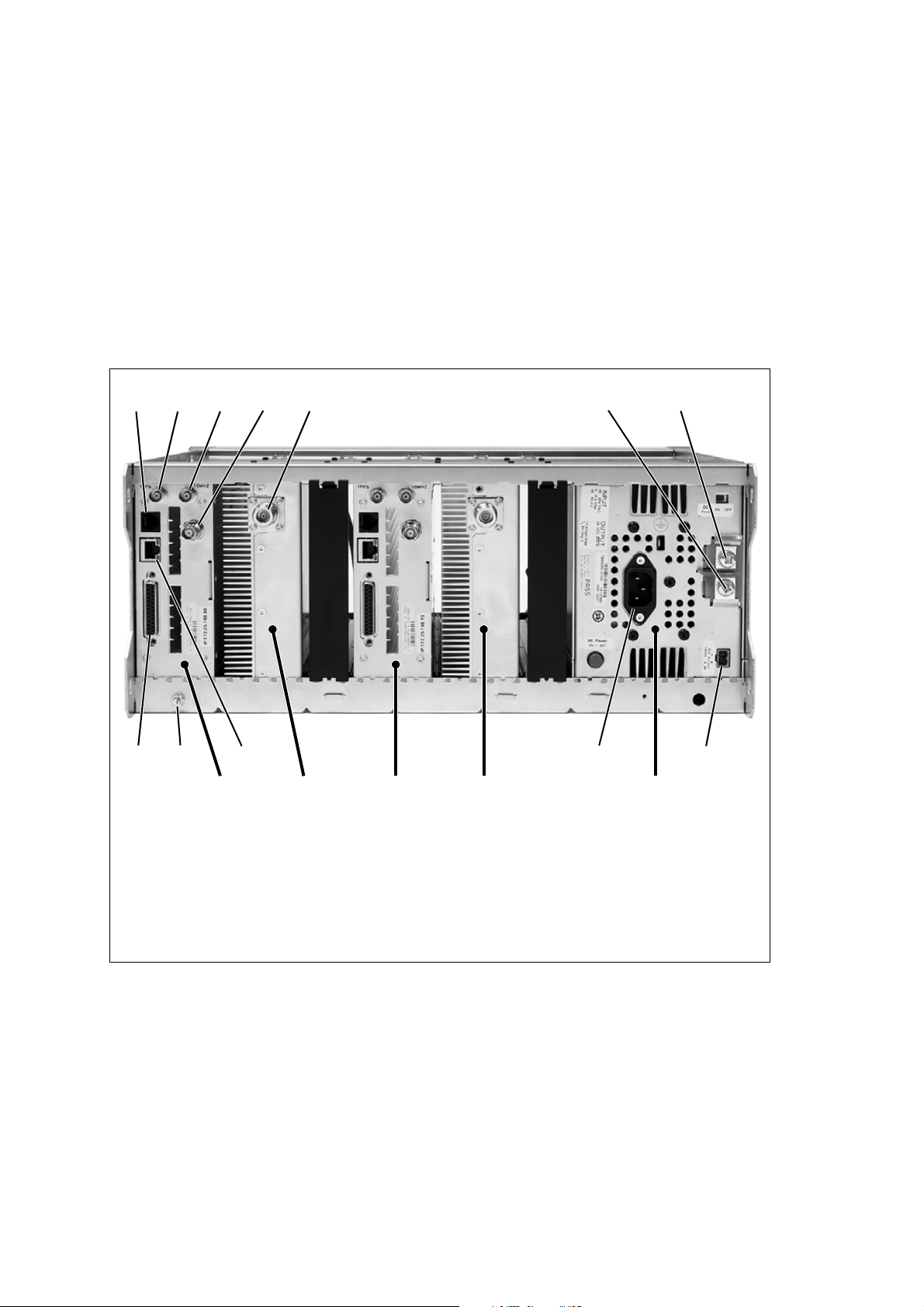
DRAFT 4
5.6 Connecting Up the Base Station
This section provides information relevant to the task of connecting up the
various inputs and outputs of the base station.
5.6.1 Connection Overview
The connections at the rear of a dual 50 W base station are identified in
Figure 5.7. External connections are all located at the rear of the subrack.
Figure 5.7 50 W base station inputs and outputs
bcd
fgh
e
1@
PA 1Reciter 1 PMU
b serial RS-232 connector
c 1 PPS input i auxiliary DC output
d external reference frequency input j AC mains input
e RF input 1) Ethernet interface connector
f RF output 1! subrack ground connector
g – VDC input 1@ system interface connector
a
PA 2Reciter 2
h + VDC input
ij1)1!
a. Factory use only.
80 Installation TB9400 Installation and Operation Manual
© Tait Electronics Limited September 2011

DRAFT 4
5.6.2 Connecting AC Power
The PMU is designed to accept a mains input of 88 to 264 VAC at 45 to
65 Hz. A standard 3-wire grounded socket outlet must be used to supply the
AC power. The socket outlet must be installed near the equipment and must
be easily accessible. This outlet should be connected to an AC power supply
capable of providing at least 600 W. The requirements of two typical AC
supplies are given in the following table.
Nominal Supply Current Requirement
115 VAC 8 A 10 A
230 VAC 4 A 6 A
a. The actual current consumption of the base station will be lower than these require-
ments (refer to the Specifications Manual for more information).
Yo u r base station should come supplied with
a power supply cord to connect the male
IEC connector on the PMU to the local AC
supply. The pins of the IEC connector on
the PMU are identified at right.
Circuit Breaker/Fuse
a
Rating
a
phase
ground
neutral
rear view
TB9400 Installation and Operation Manual Installation 81
© Tait Electronics Limited September 2011

DRAFT 4
5.6.3 Connecting DC Power
The PMU is designed to accept a nominal 12 VDC, 24 VDC or 48 VDC
input (depending on the model) with negative or positive ground. There is
a minimum DC startup threshold to prevent damaging a battery which has
little capacity left.
You must connect the DC supply from the battery to the PMU via a fuse or
DC-rated circuit breaker with a contact separation of 3 mm, and with the
appropriate rating, as shown in the table below. The DC input leads should
be of a suitable gauge to ensure less than 0.2 V drop at maximum load over
the required length of lead.
Nominal Supply
Voltage
12 VDC 10 VDC to 16.8 VDC 60 A 2 AWG / 35 mm
24 VDC 20 VDC to 33.6 VDC 30 A 5 AWG / 16 mm
48 VDC 40 VDC to 60 VDC 15 A 8 AWG / 8 mm
a. The actual current consumption of the base station will be lower than these require-
ments (refer to the Specifications Manual for more information).
b. For a length of 5 ft to 6.5 ft (1.5 m to 2 m) (typical).
Input Voltage
Range
Circuit Breaker/
Fuse Rating
a
Recommended
Wire Gauge
b
2
2
2
Terminate and insulate the DC input leads to protect them from accidentally
shorting to the subrack if the PMU is removed before the leads are
disconnected. Protective covers for the DC terminals are supplied with each
PMU.
Figure 5.8 Recommended DC power connection
Circuit Breaker
or Fuse
PMU
Battery
We recommend a screw torque of 18 – 20 lbf · in (2 – 2.25 N · m).
82 Installation TB9400 Installation and Operation Manual
© Tait Electronics Limited September 2011

DRAFT 4
5.6.4 Connecting the Auxiliary DC Power Output
The PMU can provide an auxiliary DC output when it is fitted with the
auxiliary power supply board. This board is available with an output of
13.65 VDC, 27.3 VDC, or 54.6 VDC (depending on the model), and is
current limited to 3 A, 1.5 A or 750 mA respectively. This power supply is
permanently on as soon as the base station has finished powering up, and is
available on the auxiliary output connector on the rear panel.
You can connect multiple auxiliary power supply boards in parallel for
redundancy purposes, or to provide an output greater than 40 W. Although
no active current sharing is used, auxiliary boards connected in parallel will
current-share before reaching their power limit. The failure (or switching
off) of one auxiliary board will not load any other paralleled auxiliary boards
in the circuit.
Auxiliary DC Power
Output Cabling
Network elements are supplied with a connector, as shown in Figure 5.9.
You can use this to connect the PMU’s auxiliary DC power output to
another device.
Contact your regional Tai t office for details on the full range of wiring kits
available.
Figure 5.9 Auxiliary DC power connector
Phoenix MVSTBR2.5HC/2-ST/5.08 female
TB9400 Installation and Operation Manual Installation 83
© Tait Electronics Limited September 2011

DRAFT 4
5.6.5 Connecting RF
Important Do not remove the load from the PA while it is transmitting
The RF input to the base station is via the marked BNC connector on the
rear panel of the reciter. The RF output is via the N-type connector on the
rear panel of the PA (refer to Figure 5.7 on page 80).
Cables and antennas should be of high quality construction. Solid shield
heliax type cables are best, but if braided shield cables must be used for short
distances, their braids must be silver-plated.
as this may damage the PA output stage.
Recommendations
for Installing the PA
We recommend the following installation procedures, which should protect
the PA from damage under all but the most extreme operating conditions.
1. Do not connect the PA directly to the antenna. Fit an isolator or
duplexer between the PA and the load. Fit the isolator as close as possible to the RF output connector on the PA. Do not connect any
switching equipment between the isolator and the PA, unless the
switch cannot operate while there is RF present (i.e. the base station
is transmitting).
2. Fit a surge suppressor to the antenna cabling where it enters the
building.
3. Inspect all cables and equipment connected to the base station for
defects.
Ice on the antenna, or a broken antenna, is unlikely to cause damage to the
PA.
Explanation The circuit design of the PA protects the circuitry from high VSWR. This
makes it difficult to damage the RF power device by keying the PA into a
mismatched load, or if the load deteriorates over even a short period of time
(milliseconds).
However, it is possible to damage the device if all the following conditions
happen at the same time:
■ there is a step change in the PA load (for example, the load is removed)
■ the PA is transmitting
■ the feed line loss between the PA and the mismatch is < 1 dB.
The effect of such conditions is var iabl e : s o m e d evices will not be destroyed,
and some may fail after repeated load interruptions.
84 Installation TB9400 Installation and Operation Manual
© Tait Electronics Limited September 2011

DRAFT 4
5.6.6 Connecting an External Frequency Reference
For K4 Band, the internal frequency reference accuracy is inadequate, and
an external reference (for example, the Tait T801-4) must be used. An
external reference is also required for simulcast. The external reference
frequency can be 10 MHz or 12.8 MHz, with an input level of 300 mV
5 V
. The stability of this reference should be better than 50 parts per billion
pp
(for non-simulcast) or ≤ 1 part per billion (for simulcast). The reciter
automatically detects the frequency of the external reference and configures
itself accordingly.
If an external reference is required, enable the external reference “Absent”
alarm (Configure > Alarms > Control).
Use a 50 Ω coaxial cable (RG58 or RG223) to connect the external
reference to the base station’s external reference frequency input. You can
daisy-chain up to eight base stations using T-junctions. The maximum
overall cable length is 30 m. Terminate the last connection with a 50 Ω load.
Figure 5.10 Daisy-chaining an external frequency reference input
pp
to
maximum overall cable
length is 30 m
maximum of eight base
station loads on one
frequency reference output
50 Ω termination
TB9400 Installation and Operation Manual Installation 85
© Tait Electronics Limited September 2011

DRAFT 4
5.6.7 Connecting a 1 PPS Source
A 1 PPS signal is required for simulcast base stations. This and the external
frequency reference can be provided, for example, by a Tait T801-4
Frequency Reference. For more information, see the T801-4 Installation
and Operation Manual (MBA-00033-xx).
Use a 50 Ω coaxial cable (RG58 or RG223) to connect the source to the
base station’s 1 PPS input. You can daisy-chain up to six base stations using
T-junctions. We recommend that the cable length between the first and last
load is kept to a minimum. This will reduce any propagation variation
between base stations. The maximum overall cable length is 30 m. Terminate
the last connection with a 50 Ω resistor, otherwise reflections of the 1 PPS
pulse may occur.
Figure 5.11 Daisy-chaining a 1 PPS input
The longest length of cable must be between
the source and the first base station
5.6.8 Ethernet Connection
The RJ-45 socket on the reciter’s rear panel provides the 10BASE-T or
100BASE-T Ethernet connection to the other devices in the network. Use
Cat-5 cable to connect this socket to the TaitNet P25 Network via a router
or switch.
use short lengths of cable
between each base station
maximum of six base station
loads on one 1 PPS output
50 Ω termination
If necessary, refer to “Ethernet Connector” on page 109 for a list of Ethernet
connection pin allocations.
86 Installation TB9400 Installation and Operation Manual
© Tait Electronics Limited September 2011

DRAFT 4
5.6.9 Connecting General Purpose Inputs and Outputs
The base station has a number of general purpose inputs and outputs. These
are connected via the 25-way D-range on the rear panel.
The pin allocations for the D-range connector are given in the following
table. Not all pins are used in this release of the base station.
Pin Signal Name Signal Type Notes
1
2
3
4
5
not used
6
B
1$
C
1%
D
1^
E
1&
F
1*
G
1(
H
2)
I
2!
J
2@
1)
2#
1!
2$
1@
2%
1#
external view
7
8
9
10
11 digital in 1
12 digital in 2
13 + 5.2 VDC output power output maximum current 200 mA
14 digital in 3
15 digital in 4
16 digital in 5
17 digital in 6
18 digital in 7
19 digital in 8
20 digital in 9
21 digital in 10
22 digital in 11
23 digital in 11
24 not used
25 ground ground
input
input
5 V TTL logic
active low
5 V TTL logic
active low
TB9400 Installation and Operation Manual Installation 87
© Tait Electronics Limited September 2011

DRAFT 4
88 Installation TB9400 Installation and Operation Manual
© Tait Electronics Limited September 2011

DRAFT 4
6 Maintenance
The base station is designed to be very reliable and should require little
maintenance. However, performing regular checks will prolong the life of
the equipment and prevent problems from happening.
It is beyond the scope of this manual to list every check that you should
perform on your base station. The type and frequency of maintenance
checks will depend on the location and type of your system. The checks and
procedures listed below can be used as a starting point for your maintenance
schedule.
Performance Checks We suggest you monitor the following operational parameters using the web
interface:
■ VSWR
■ DC input voltage, especially on transmit
■ receiver sensitivity
■ any temperature alarms.
These basic checks will provide an overview of how well your base station
is operating.
Reciter If an external frequency reference is not used, check UHF reciters for
frequency drift after 3 months’ service and annually thereafter. If the drift is
> 0.5 ppm, adjust the carrier frequency offset. For details, see the Help.
PA There are no special maintenance requirements for the PA.
PMU There are no special maintenance requirements for the PMU. However, we
suggest that you periodically check that the screws on the DC input
terminals are tight. They may work loose with thermal cycling. Also, if you
are using battery back-up, you should check the batteries regularly in
accordance with the manufacturer’s recommendations.
Ventilation The base station has been designed to have a front-to-back cooling airflow.
We strongly recommend that you periodically check and maintain the
ventilation requirements described in “Equipment Ventilation” on page 64
to ensure a long life and trouble-free operation for your base station.
Cooling Fans The cooling fans have a long service life and have no special maintenance
requirements. You can use the web interface to configure the base station to
generate an alarm if any of the front panel cooling fans fails. Refer to the
Help for more details.
TB9400 Installation and Operation Manual Maintenance 89
© Tait Electronics Limited September 2011

DRAFT 4
90 Maintenance TB9400 Installation and Operation Manual
© Tait Electronics Limited September 2011

DRAFT 4
7 Troubleshooting
Check that all front and rear connectors and cables are in place, and that
power switches are on. If problems persist, contact your regional Ta it office.
Symptom Possible Cause Action
Alarm LED red and steady
(not flashing)
Desired feature is not
operating
Tx stuck on Tx and Rx frequencies are
Power LED on front panel
is on, but keypad does not
work
No power or LEDs on front
panel
The base station appears to
make random
transmissions
PA has low power Channel is configured to
The base station is in
Offline mode
Feature license missing Check that you have the necessary feature licenses
Feature license present but
feature is not enabled
the same
Keypad is disabled Check that the keypad is enabled in the web
System control bus not
connected to front panel
Pins bent on 15-pin
D-range plug on front
panel
CWID feature enabled No action: CWID transmissions are made according
low power
Use the web interface to put the base station in
Online mode
(refer to “Licenses” on page 18 and the Help)
Use the web interface to enable the feature.
Reconfigure Tx and Rx with different frequencies
interface (Configure > Base Station >
Miscellaneous)
Check cable connections
Replace or repair D-range plug
to configuration settings
Use the web interface to check the power settings
?
?
PA may have suffered
partial damage
Test tones can’t be heard
Lost or forgotten base
station IP address
TB9400 Installation and Operation Manual Troubleshooting 91
© Tait Electronics Limited September 2011
IMBE does not pass on
tones higher than 400 Hz
Replace module and send faulty module for
servicing
Ensure test tones are less than 400 Hz
Procedure TBD

DRAFT 4
92 Troubleshooting TB9400 Installation and Operation Manual
© Tait Electronics Limited September 2011

DRAFT 4
8 Replacing Modules
Caution The 100 W PA and PMU weigh between 9.3 lb
(4.2 kg) and 15.4 lb (7 kg) each. Take care when handling these modules to avoid personal injury.
Important The cooling fans are mounted on the front panel and will
only operate when the panel is fitted correctly to the front
of the subrack. To ensure adequate airflow through the base
station, do not operate it for more than a few minutes with
the front panel removed (e.g. for servicing purposes). Both
the PMU and PA modules have built-in protection mechanisms to prevent damage from overheating.
TB9400 Installation and Operation Manual Replacing Modules 93
© Tait Electronics Limited September 2011

DRAFT 4
8.1 Saving the Base Station’s Configuration
Before replacing a module in the base station, you should decide whether
you need to save its configuration data. If you are unsure whether you have
a record of the configuration, backup and save the configuration file before
removing any modules. Once you have replaced the module, you will be
able to restore the original configuration to the base station.
If one or more of the modules is faulty, you may be unable to save the
configuration. In this case, you will have to restore the configuration from a
back-up file. Refer to the Help for more information.
94 Replacing Modules TB9400 Installation and Operation Manual
© Tait Electronics Limited September 2011

DRAFT 4
8.2 Preliminary Disassembly
Hot-pluggable
Modules
Disconnecting the
Power
The reciter, PA and front panel are hot-pluggable and can be removed
without powering down the whole base station. These modules can also be
removed without disrupting the system control bus communications with
the other modules in the subrack.
Important Before removing a PA, first disconnect the DC input, trans-
mit forward input and transmit reverse output, followed by
the RF output. After refitting the PA, reconnect the RF
output first, followed by the transmit forward input, transmit reverse output, and then the DC input.
If you want to disconnect the power before working on the base station,
follow these steps.
Caution Before disconnecting the battery supply leads from
the PMU, open the circuit breaker or disconnect the
supply leads from the battery.
1. Turn off the AC
2. Also at the rear of the PMU disconnect the mains
supply leads, and the auxiliary DC supply lead
b and DC c switches at the rear of the PMU.
d and battery e
f (if fitted).
bcdef
TB9400 Installation and Operation Manual Replacing Modules 95
© Tait Electronics Limited September 2011

DRAFT 4
Remove the Front
Panel
1. Using a Pozidriv PZ2 screwdriver, undo the fastener at each end of
the front panel
b with a quarter turn counterclockwise.
c
lockedunlocked
b
2. Place a finger in the recess
and pull the front panel away from the subrack.
c provided at each end of the front panel
Cable Retaining
Clips
The cable retaining clips are used to hold cables in position at the top of the
subrack so that they do not interfere with the mounting of the front panel,
or interrupt the airflow through the base station.
If you need to remove any front panel cables, simply pull the front of the
cable retaining clip down and then slide it out from the subrack until it
reaches the end of its travel.
96 Replacing Modules TB9400 Installation and Operation Manual
© Tait Electronics Limited September 2011

DRAFT 4
8.3 Replacing a Reciter
Removal 1. If you have not already done so, carry out the instructions in “Pre-
liminary Disassembly” on page 95.
2. At the rear of the reciter, unplug the RF input cable
c, and the external reference d and 1 PPS e cables (if fitted).
cables
3. At the front of the reciter, unplug the transmit reverse
forward
ends of the system control bus cable
4. Loosen the screw securing the retaining clamp
clamp through 90° to clear the module.
5. Slide the reciter out of the subrack, taking care not to damage any of
the cables.
g cables, and move both cables to one side. Unplug both
h and remove it.
b, any system
f and transmit
i and rotate the
d
f
e
b
c
h
g
i
TB9400 Installation and Operation Manual Replacing Modules 97
© Tait Electronics Limited September 2011

DRAFT 4
Refitting 1. Slide the replacement reciter into the subrack and secure it with the
retaining clamp.
2. Reconnect all the front and rear panel cables previously disconnected.
Ensure the front panel cables are positioned correctly, and retained
where required by the cable retaining clips in the top of the subrack
(refer to “Appendix B – Inter-Module Connections” on page 111).
3. Tighten the nut on the SMA connector to a torque of 8 lbf ·in
(0.9 N·m).
4. Carry out the instructions in “Final Reassembly” on page 107.
98 Replacing Modules TB9400 Installation and Operation Manual
© Tait Electronics Limited September 2011

DRAFT 4
8.4 Replacing a Power Amplifier
Important Before removing a PA, first disconnect the DC input, trans-
mit forward input and transmit reverse output, followed by
the RF output. After refitting the PA, reconnect the RF
output first, followed by the transmit forward input, transmit reverse output, and then the DC input.
Removal 1. If you have not already done so, carry out the instructions in “Pre-
liminary Disassembly” on page 95.
2. At the front of the PA, unplug the DC input
and transmit reverse
Unplug both ends of the system control bus cable
3. At the rear of the PA, unplug the RF output cable.
4. Loosen the screw securing the retaining clamp(s)
clamp(s) through 90° to clear the module.
5. Slide the PA out of the subrack, taking care not to damage any of the
cables.
d cables, and move the cables to one side.
b, transmit forward c
e and remove it.
f and rotate the
b
e
d
c
f
50 W PA 100 W PA
be d cff
Refitting 1. Slide the replacement PA into the subrack and secure it with the
retaining clamp(s).
2. At the rear of the PA, connect the RF output cable.
3. At the front of the PA, connect the transmit forward and transmit
reverse cables, followed by the DC input cable.
4. Reconnect all the other front and rear panel cables previously
disconnected. Ensure the front panel cables are positioned correctly,
and retained where required by the cable retaining clips in the top of
TB9400 Installation and Operation Manual Replacing Modules 99
© Tait Electronics Limited September 2011

DRAFT 4
the subrack (refer to “Appendix B – Inter-Module Connections” on
page 111).
5. Tighten the nut on the SMA connector to a torque of 8 lbf ·in
(0.9 N·m).
6. Carry out the instructions in “Final Reassembly” on page 107.
100 Replacing Modules TB9400 Installation and Operation Manual
© Tait Electronics Limited September 2011
 Loading...