

Page 1
User Guide
Bedienungsanleitung
Guide de lutilisateur
Guía del Usuario
T2035
T2030
Page 2
© Copyright Tait Electronics Ltd August 2004. All rights reserved.
1
Page 3

Declaration of Conformity (Europe)
Dansk Undertegnede Tait Electronics Ltd erklærer herved, at
følgende udstyr T2000 overholder de væsentlige krav
og øvrige relevante krav i direktiv 1999/5/EF.
Se endvidere: http://eudocs.taitworld.com/
Deutsch Hiermit erklärt Tait Electronics Ltd die Übereinstimmung
des Gerätes T2000 mit den grundlegenden
Anforderungen und den anderen relevanten
Festlegungen der Richtlinie 1999/5 EG.
Siehe auch: http://eudocs.taitworld.com/
Ελληνικός Με την παρουσα Tait Electronics Ltd δηλωνει οτι
T2000 συµµορφωνεται προσ τισ ουσιωδεισ
απαιτησεισ και τισ λοιπεσ σχετικεσ διαταξεισ τησ
οδηγιασ 1999/5/ΕΚ.
βλέπε και: http://eudocs.taitworld.com/
English Tait Electronics Ltd declares that this T2000 complies
with the essential requirements and other relevant
provisions of Directive 1999/5/EC.
See also: http://eudocs.taitworld.com/
Español Por medio de la presente Tait Electronics Ltd declara
que el T2000 cumple con los requisitos esenciales y
cualesquiera otras disposiciones aplicables o exigibles
de la Directiva 1999/5/CE.
Vea también: http://eudocs.taitworld.com/
2
Page 4

Declaration of Conformity (Europe)
Français Par la présente, Tait Electronics Ltd déclare que
l'appareil T2000 est conforme aux exigences
essentielles et aux autres dispositions pertinentes de la
directive 1999/5/CE.
Voir aussi: http://eudocs.taitworld.com/
Italiano Con la presente Tait Electronics Ltd dichiara che questo
T2000 è conforme ai requisiti essenziali ed alle altre
disposizioni pertinenti stabilite dalla direttiva 1999/5/CE.
Vedi anche: http://eudocs.taitworld.com/
Nederlands Hierbij verklaart Tait Electronics Ltd dat het toestel
T2000 in overeenstemming is met de essentiële eisen
en de andere relevante bepalingen van richtlijn
1999/5/ EG.
Zie ook: http://eudocs.taitworld.com/
Português Tait Electronics Ltd declara que este T2000 está
conforme com os requisitos essenciais e outras
provisões da Directiva 1999/5/CE.
Veja também: http://eudocs.taitworld.com/
Suomi Tait Electronics Ltd vakuuttaa täten että T2000
tyyppinen laite on direktiivin 1999/5/EY oleellisten
vaatimusten ja sitä koskevien direktiivin muiden ehtojen
mukainen.
Katso: http://eudocs.taitworld.com/
Svensk Härmed intygar Tait Electronics Ltd att denna T2000
står I överensstämmelse med de väsentliga
egenskapskrav och övriga relevanta bestämmelser
som framgår av direktiv 1999/5/EG.
Se även: http://eudocs.taitworld.com/
3
Page 5
4
Page 6

User Guide ................................................................................. 7
Safety Warnings .................................................................. 8
Getting Started .................................................................... 11
Making a Call ....................................................................... 12
Receiving Calls .................................................................... 13
Returning Calls .................................................................... 14
Additional Information ......................................................... 15
Removing the Radio from the Vehicle ................................ 17
Installation ............................................................................ 18
Bedienungsanleitung .............................................................. 29
Sicherheitsvorkehrungen .................................................... 30
Inbetriebnahme ................................................................... 33
Rufaussendung ................................................................... 34
Rufempfang ......................................................................... 35
Rückrufe ............................................................................... 36
Zusätliche Informationen ..................................................... 37
Geräteentnahme aus dem Fahrzeug ................................. 39
Montageanleitung ................................................................ 40
Guide de l’utilisateur ................................................................ 53
Précautions de sécurité ...................................................... 54
Mise en route ....................................................................... 57
Lancement d’un appel ........................................................ 58
Réception d’un appel .......................................................... 59
Rappels ................................................................................ 60
Informations complémentaires ........................................... 61
Retirer la radio du véhicule ................................................. 63
Installation de votre radio .................................................... 64
5
Page 7
Guía del Usuario ....................................................................... 75
Medidas de seguridad ........................................................ 76
Para comenzar .................................................................... 79
Cómo hacer una llamada ................................................... 80
Cómo recibir una llamada .................................................. 81
Cómo contestar las llamadas ............................................. 82
Información adicional .......................................................... 83
Cómo sacar la radio del vehículo ....................................... 85
Instalación de la Radio ....................................................... 86
..................................................................................................... 97
.............................
.....................
.....................
.......................................................... 99
.....................
.....................
.......................................................... 100
.......................................................... 101
.......................................................... 102
.....................
.
............
.......................................................... 103
.......................................................... 105
.......................................................... 105
.......................................................... 106
.........
6
Page 8

T2030
T2035
II
II
User Guide
English
7
Page 9
Safety Warnings
• Switch the radio off at petrol filling stations.
• Switch the radio off in the vicinity of explosive devices,
such as in a quarry that uses blasting techniques.
• Use of a handheld microphone or a radio while driving
could contravene the legislation that applies in your
country or state. Please check the vehicle regulations
in your own country.
EN60950 Compliance
This radio complies with the European Union standard
EN60950, when operated up to the rated 33% duty cycle of
two minutes transmit and four minutes receive, and at an
ambient temperature of 30°C or lower. Operation outside
these limits may cause the external temperature of the radio
WARNING
to rise higher than specified by EN60950.
To ensure compliance with EN60950, the radio should be
mounted in such a position that will prevent the user from
coming into contact with the radio’s heatsink.
FCC RF Exposure Limits
This product generates radio frequency energy during
transmissions. This device must be restricted to workrelated use in an occupational/controlled exposure
environment. The radio operator must have control of the
exposure conditions and duration of all persons exposed to
the antenna of this transmitter to satisfy FCC RF exposure
compliance.This device is not approved for general
population use.
The following conditions apply to the use of this radio:
• It must only be used with authorised accessories and
antennas.
• The operator must ensure that the minimum safe distance
of 0.9m (35 inches) between persons and the antenna is
not exceeded during transmissions.
• Do not exceed a duty cycle ratio of 50% transmit mode to
stand-by or receive modes. The radio is in transmit mode
when the PTT key on the microphone is pressed and the
TX indicator shows in the display window.
8
English
Page 10

Compliance Information
Health, safety and
electromagnetic
compatibility in
Europe
In the European Community, radio and
telecommunications equipment is regulated by
Directive 1999/5/EC, also known as the Radio and
Telecommunications Terminal Equipment (R&TTE)
directive. The requirements of this directive include
protection of health and safety of users, as well as
electromagnetic compatibility.
Intended purpose of product
This product is an FM radio transceiver. Its intended
purpose is for radio communication in Private Mobile
Radio (PMR) services or Public Access Mobile Radio
(PAMR) services.
Note: This product can be programmed for
frequencies or emissions that may make its use
illegal. A licence must be obtained before this product
Electromagnetic
compatibility in
European
vehicles
is used. All licence requirements must be observed.
Limitations may apply to transmitter power, operating
frequency, channel spacing, and emission.
Declaration of conformity
Brief Declarations of Conformity appear on page 2.
The formal Declaration of Conformity can be
downloaded from http://eudocs.taitworld.com/.
A signed and dated paper copy of the Declaration of
Conformity can be obtained from Tait Europe Ltd.
In the European Community, radio equipment fitted to
automotive vehicles is regulated by Directive 72/245/
EEC, as amended by 95/54/EC. The requirements of
this directive cover the electromagnetic compatibility
of electrical or electronic equipment fitted to
automotive vehicles.
Note: To meet the requirements of Directive
72/245/EEC (as amended by 95/54/EC), installation
English
9
Page 11

Compliance Information
of this product in a vehicle must be performed
according to the instructions provided, and any
guidelines of the vehicle manufacturer.
Radio frequency
emissions limits
in the USA
Additional
information
Part 15 of the FCC Rules imposes RF emission limits
on electronic equipment to prevent interference to
reception of broadcast services.
This device complies with Part 15 of the FCC Rules.
Operation is subject to the condition that this device
does not cause harmful interference.
Note: Changes or modifications to this device that are
not expressly approved by Tait Electronics Ltd may
make its use illegal.
For product details and contact details of Tait offices,
visit http://www.taitworld.com/.
For technical assistance, visit
http://support.taitworld.com/.
10
English
Page 12
Getting Started
Introduction The T2030/35 Series
to make the following types of call:
• Speech calls to other radios, both in your own fleet
and in different fleets.
• Speech calls on a telephone network.
• Status message calls to a preprogrammed destination
(such as your despatcher).
Variation in
radio setup
Your T2030/35
can be configured to suit the needs of your fleet. For this
reason, some features described in this guide may
operate differently on your radio.
If a feature does not operate as described, consult your
Tait dealer for further assistance.
II is microprocessor controlled so that it
II of trunked radios may be used
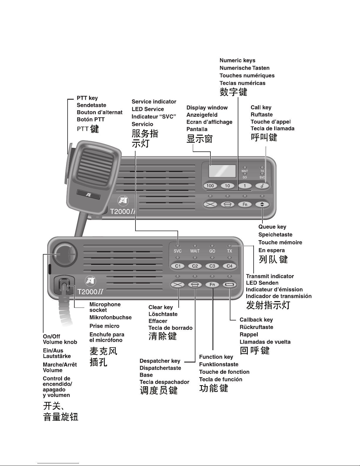
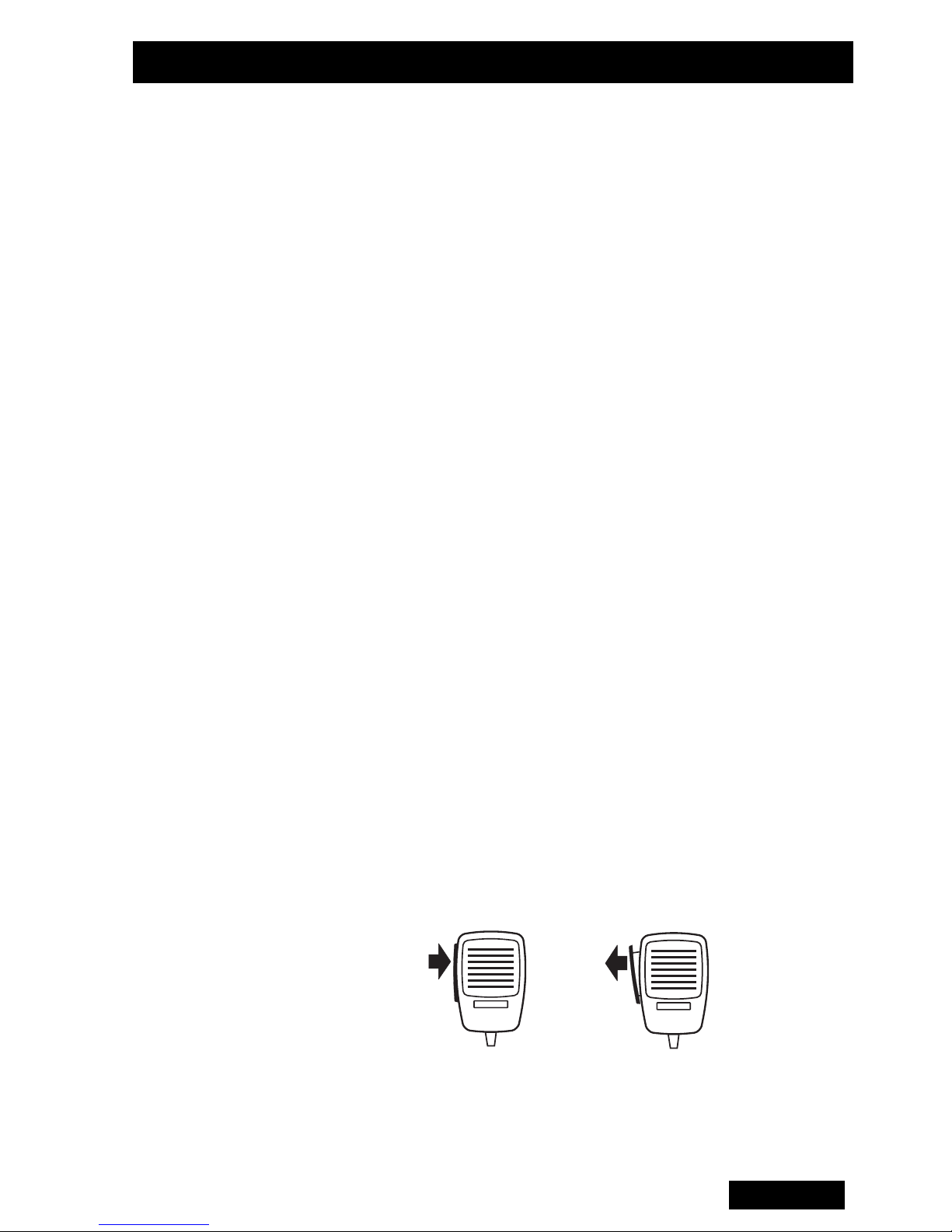
Switching the
radio on
Using the
Microphone
and PTT key
To switch the radio on, turn the On/Off-Volume control
to about one third of its maximum setting. You may need
to re-adjust the volume when you receive your first call.
The SVC (service) indicator will normally glow within a
few seconds. If it does not, you may be outside your
network’s coverage area.
During a call, use the PTT key to switch the radio
between receive and transmit modes.
Press the PTT key to talk, release it to listen.
The TX indicator glows during transmission.
English
11
Page 13

Making a Call
This section describes how to select a call destination
and set up the call. Depending on the type of radio you
have and the type of call you want to make, refer to the
appropriate section below.
T2030
T2035
II
II
All calls available on the T2030II are preset by the
person who programs your radio. Depending on how
your T2030
calls to various destinations including other radios on
your network and telephone numbers.
To set up a call, press one of the Call ( to )
keys, or the Despatcher ( ) key. All of these keys
can be preset to call different destinations. The
Despatcher ( ) key is most often set to call a base
station or despatcher.
The person who programs your radio will advise you of
the destination called by each key.
To make a call on the T2035II :
II is programmed, you will be able to make
C1
C4
1 Use the numeric keys to enter the number you want
to call.
2 Press the Call ( ) key to initiate the call.
The person who programs your radio will advise which
preset call and personal ID numbers you should use to
call different destinations.
Depending on programming, you may be able to make
up to three different types of calls:
• Programmed preset calls to any destination.
• Direct calls to the personal IDs of others on your
network.
• Group calls to two or more IDs.
12
English
Page 14

Receiving Calls
When you
receive a
call
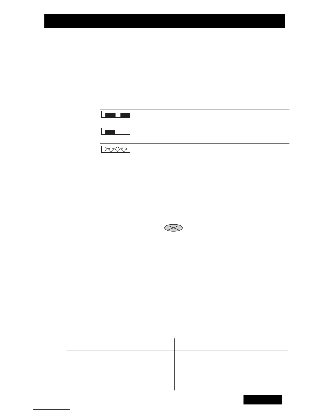
The tones used to alert you to an incoming call may
vary, depending on how your radio is programmed and
the type of network you are using.
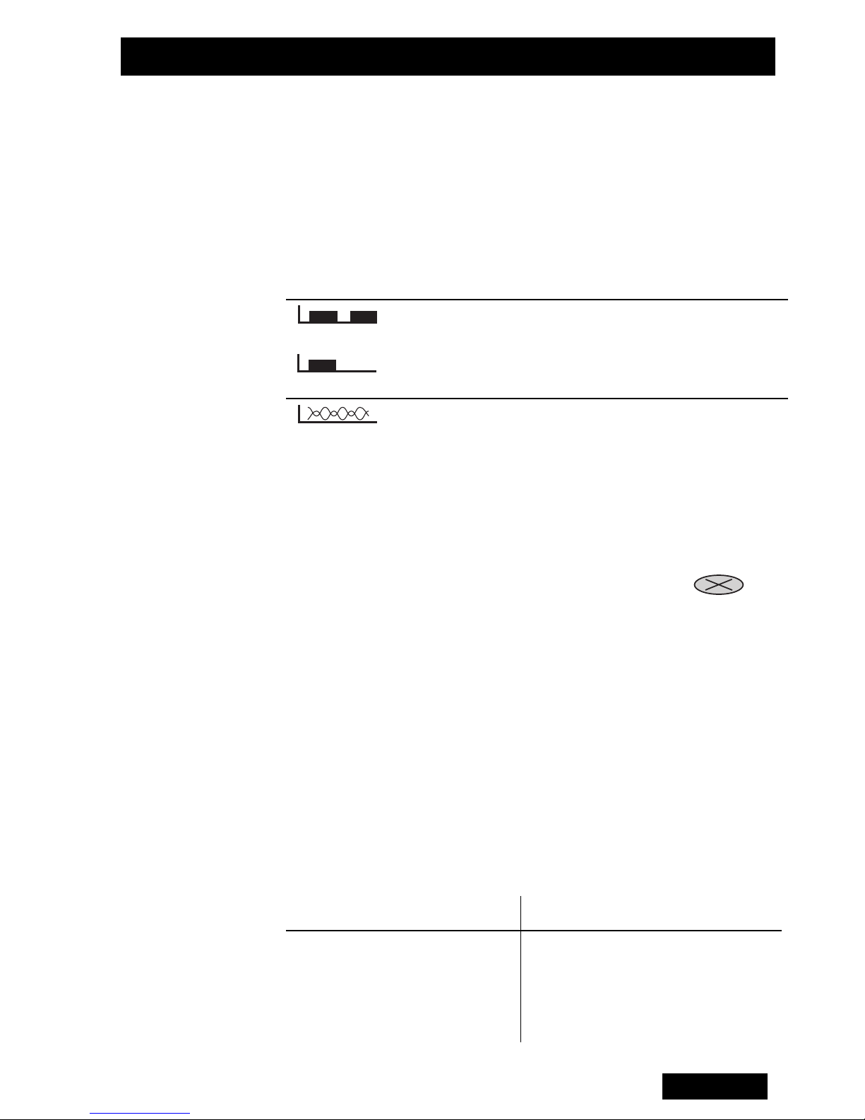
Both types of alert tone are illustrated below, alongside
instructions for answering the different types of incoming
call.
Tone: To Answer:
This is a Direct Call. When the GO
Two tones
or
A single tone
A ringing tone
indicator lights, lift the microphone
and respond to your caller.
This is a Request Call. Either:
1 Lift the microphone off-hook.
• Wait while your radio sets up the call.
• Respond when the WAIT indicator
Identifying
the caller
T2030
T2035
II
II
goes out and the GO indicator lights,
or
2 Press the Clear ( ) key to reject
the call.
If the call is from a location that is programmed as a
preset for your radio, then the radio will display the
preset ID as follows:
The appropriate preset key indicator will light.
The caller’s preset number will show on the display.
Additional information may be displayed on the T2035
If the call is:
From within your fleet
The T2030/35
the caller’s fleet ID
II
displays:
II:
From outside your fleet
From a telephone
Unidentifiable
.1.
.2. or .3.
.4.
English
13
Page 15

Returning Calls
Use the memory features described below to reestablish earlier calls and return unanswered calls.
Callback When an incoming call finishes, your radio stores the
caller’s number. The CALLBACK indicator glows in the
T2030
the display of the T2035
To return the call, press the Callback () key
(T2030
the GO indicator to light, and proceed as usual.
You may also be able to initiate a callback by squeezing
the PTT key briefly (depending on how your radio is
programmed).
Redial The last number you called is also stored in your radio’s
memory. To call that number again, press the PTT key.
If your radio is in callback mode, press the Clear ()
key to discard the callback ID before redialling.
Call Queuing
Your T2035
II, and the caller’s preset number or ID flashes on
II.
II), or the Call ( ) key (T2035II). Wait for
II may be programmed to queue up to 20
(T2035
II
only)
unanswered call IDs.
To access the queue, press the Queue ( ) key and
hold the Despatcher ( ) key for approximately one
second. The QUEUE indicator will light. Press the
Despatcher ( ) key again to leave the queue.
In queue mode, press the Queue key to scroll through
the list of IDs. When you reach the end of the list, the
radio will beep and reverse the scrolling direction.
To return a call to any of the listed IDs, press the PTT
key or the Call ( ) key when that ID is displayed. To
delete an ID from the list, press the Clear () key.
14
English
Page 16

Additional Information
Status Calls Status Calls permit the rapid exchange of simple
messages without voice conversation. Your radio can
have messages such as “En route” or “At lunch”
preprogrammed.
Emergency
Operation
Despatcher
Operation
To utilise the Emergency Operation, your radio must be
connected to a hidden emergency switch, and must be
programmed to make emergency calls.
To make an emergency call, follow the steps below:
• Operate the hidden switch.
• The radio will then send a message to alert the called
party that you are in distress.
• While an emergency call is in progress, your radio will
quietly switch in and out of transmit mode so that
activity around the radio can be monitored.
• You can reset the radio yourself by switching it off and
on.
The T2030/35
mounted on top of its companion T2008 Power Supply
II can be used for Despatcher Operation,
which is available separately. The radio must be
programmed to be used as a despatcher.
Information
codes when
making a call:
Codes
“0. .1” flashing System is busy
“0. . 2” flashing Call unavailable
“0. . 3” flashing Number unobtainable
“0. . 4” flashing Called party busy
T2030/35
II
English
15
Page 17

Additional Information (continued)
Economy
Mode
Maximum Call
Duration
Maintenance Your T2030/35
To conserve battery power, your radio may be
programmed to dim or turn off the display and the
keypad backlighting after a preset period of inactivity.
Operate the PTT or any front panel key to restore the
radio to full operation. (Valid activity on the selected
channel will have the same effect.)
Your radio is programmed with a timer that limits the
length of transmissions. The radio will sound a warning
before it stops transmitting.
other than ensuring that all cables and connections are
secure, and that no damage has occured to the antenna
or wiring.
II requires no regular maintenance,
Troubleshooting
If none of the front panel indicators light when you turn
the radio on, it is likely that no power is getting through
to the radio. Check all the leads, in-line fuses and
connections between the battery and the radio.
If the fault persists, contact your Tait dealer.
16
English
Page 18
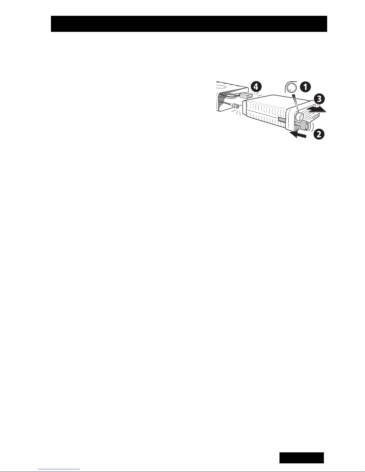
Removing the Radio from the Vehicle
Removing the
radio from its
cradle
For security, you may remove the radio from the
vehicle.The radio can be removed from its cradle using
the special key as follows:
1 Switch the radio off.
2 Insert the key in the
slot beside the volume
control as shown.
3 Holding the radio’s
front panel by its edges, pull the radio towards you
until it is clear of the cradle.
4 Disconnect the antenna and other cables from the
rear of the radio.
5 Remove the radio.
English
17
Page 19

18
English
Page 20

English
19
Page 21
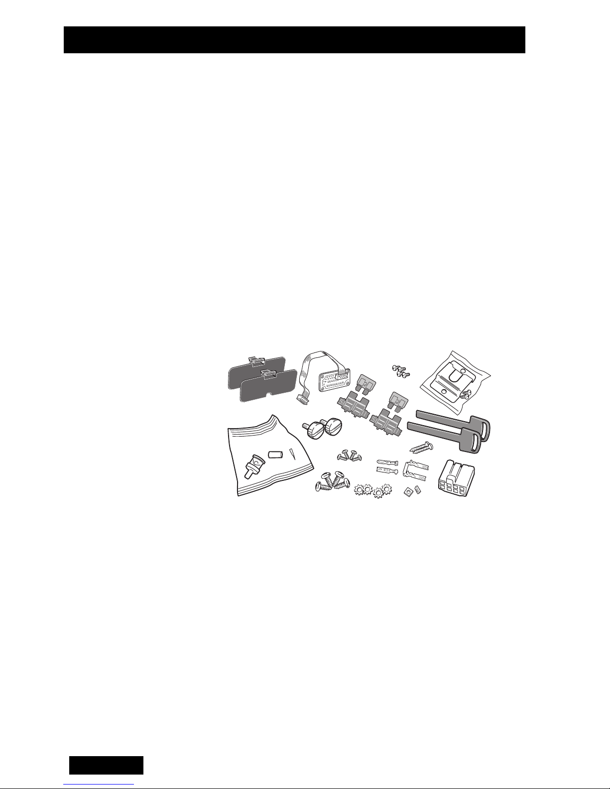
Installation
Components of
II
the T2000
Radio Kit
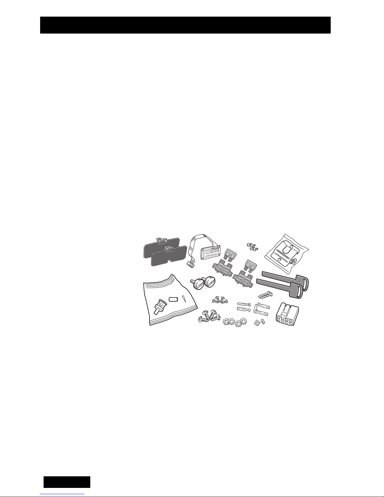
The T2000
• T2000
• Microphone
• Complete Cradle
• 4 Ohm Speaker (not for internal speaker models)
Installation Kit
• Two-way Hermaphroditic
Connector (1)
• Socket Receptacle (2)
• 10A 12V Blade Fuse (2)
• In-line Crimp Fuse Holder
(2)
II Radio kit includes the following parts:
II Radio Unit
• BNC Antenna Crimp Plug
• Cradle Keys (2)
• Power Cable (5m)
• Self Tapping Screw (4)
• Shakeproof Washer
(4)
• Microphone Clip Kit (1)
• Control Head Mounting
Bracket (T2020
T2040
II only)
II and
Recommended
Installation
Tools
18
English
• Portable Drill
• Centre Punch
• Drill Bits: 4mm for self-tapping screws, 6mm for nuts
and bolts
•“Pozidriv” Screwdrivers
• BNC Crimp Tool (e.g. Transradio England Duo Crimp
894)
• In-line Power Meter capable of measuring forward and
reflected power at the operating frequency of the radio
• Hammer
Figure 1: Radio Kit Components
Page 22

Installation
Installation
Planning
Occupant’s
Safety
To ensure trouble-free, efficient installation, inspect the
vehicle and determine how and where the antenna,
radio and accessories are to be mounted.
It is possible to remote-mount the T2020
models as these have alphanumeric keypads, with the
control head separate from the radio chassis.
This enables the radio to be mounted in a discrete
location, e.g. the rear luggage space, with the control
head mounted in a convenient position for the vehicle’s
occupants. See the M2000 service manual, available
from your Tait dealer, for details of this modification.
Check that the chosen locations for the radio and
accessories do not endanger the vehicle occupants.
Overhead mounting is not recommended, especially
II and T2040II
without an additional safety strap. Check that the radio
can be conveniently operated when seat belts are worn.
Caution: To prevent interference with vehicle electronic
systems (such as ignition and anti-skid devices), the
radio, its antenna and wiring should be mounted away
from these units and their associated cables.
Allow sufficient airflow around the radio to permit
adequate cooling. Once you have found a suitable
mounting position for the radio, hold it (fitted in the
cradle) in the proposed mounting position and check
there is clearance behind it for the heatsink, cables, etc.
Check that the position provides a large enough flat
surface that the cradle will not be distorted.
Important: To ensure compliance with EN60950, the
radio should be mounted in such a position that will
prevent the user from coming into contact with the
radio’s heatsink.
English
19
Page 23
Installation
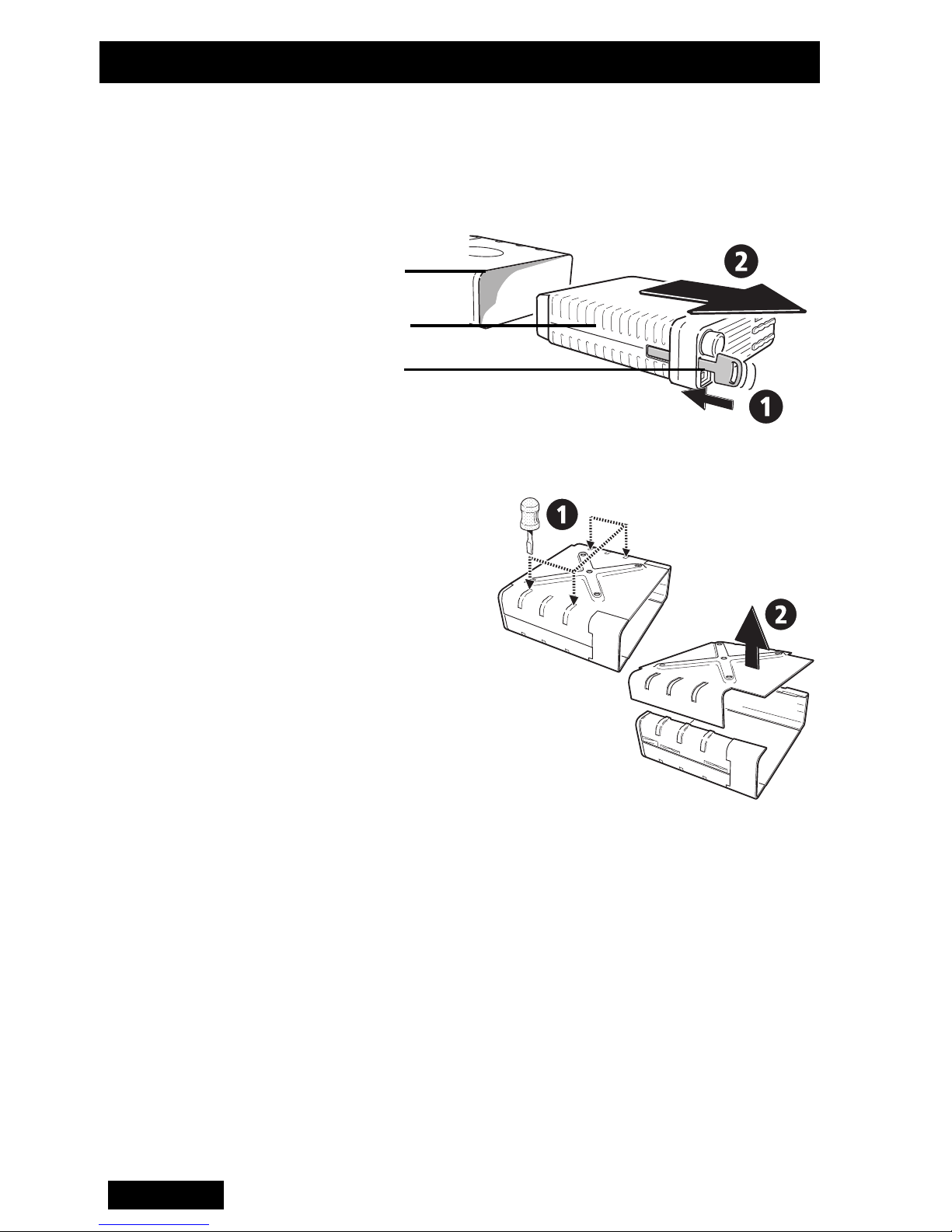
To Disassemble
the Cradle
1 Remove the radio from its cradle by sliding the plastic
key supplied with the radio fully into the slot on the left
front of the radio unit. The radio will now slide out
forwards from the cradle, as shown below:
Cradle
Radio Unit
Plastic Key
Figure 2: Cradle and Key
2 Disassemble the
cradle by placing it
on a firm surface
and applying
pressure down on
one of the middle
ribs of the plastic
side moulding with
a screwdriver. This
will release the
ribs along this
edge from the
Figure 3: Cradle Disassembly
slots in the metal cover with which they mate. A
similar approach will release the other edge of the
metal cover which can now be lifted clear (Figure 3).
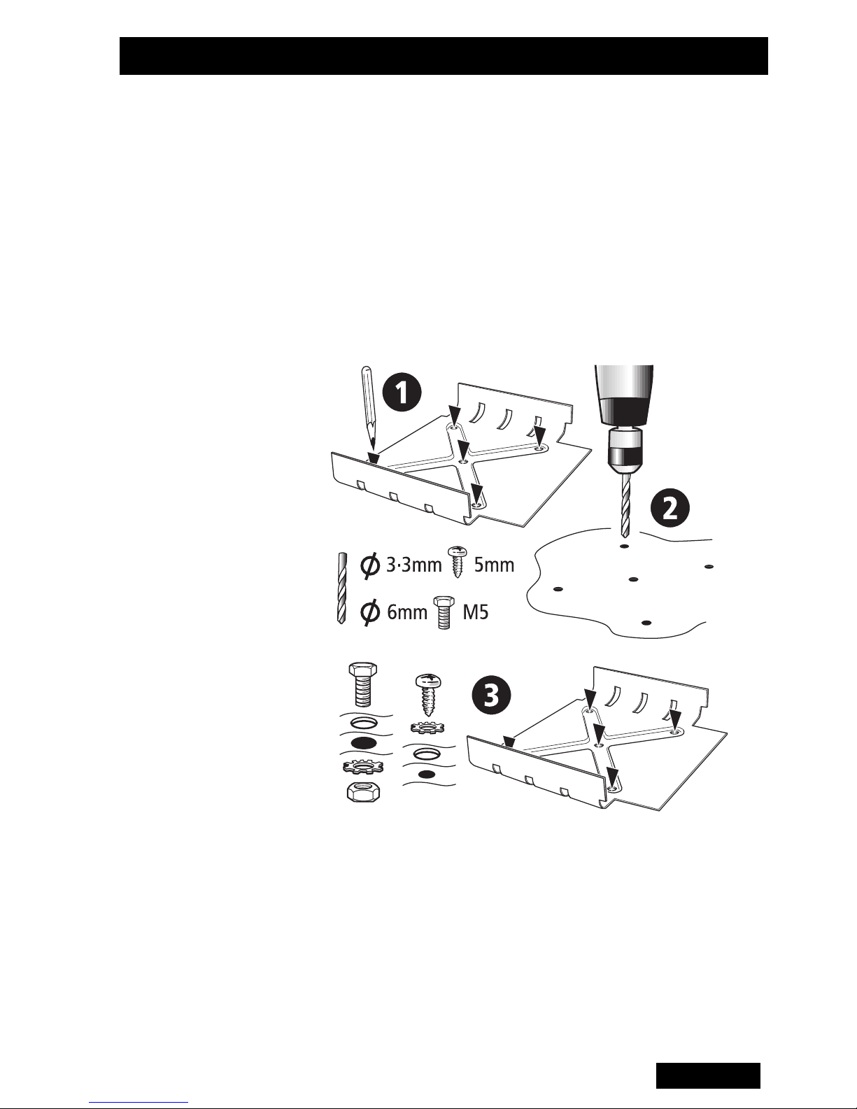
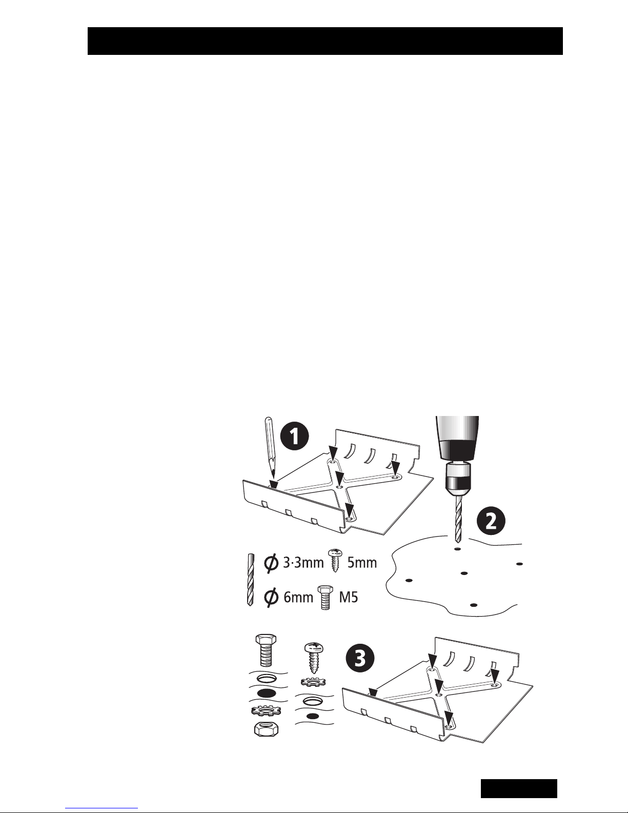
Mounting Hold the drilled half of the metal cradle cover in the
position chosen for the radio and use the four cradle
cover mounting holes as a template to mark the
locations for drilling (see figure 4). Ensure that drilling at
the selected points will not damage existing wiring.
Indent the drilling positions with a centre punch and drill
4mm holes for self-tapping screws, or 6mm holes for
20
English
Page 24
Installation
nuts and bolts. Reduce the hole size if using self-tapping
screws in metal that is less than 1mm thick.
Drill any additional holes required for cables and fit them
with suitable grommets or bushings.
Secure the metal cradle cover to the mounting points
with the M5 self-tapping screws supplied, or with M5
nuts and bolts. Ensure that tightening the screws or
bolts does not distort the cradle.
Figure 4: Mounting
English
21
Page 25
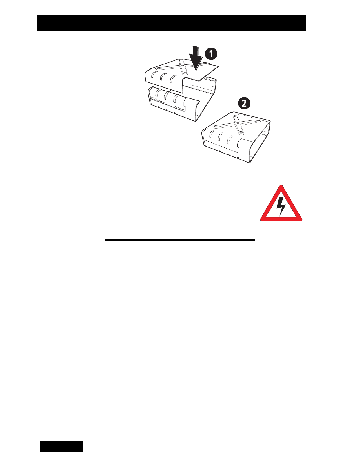
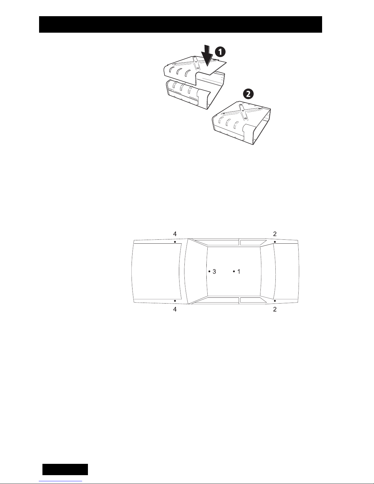
To Reassemble
the Cradle
Installation
Figure 5: Cradle Reassembly
Antenna
Installation
To comply with FCC RF exposure limits,
this product must be installed using an
antenna with a gain specified below:
WARNING
Product Antenna Gain
T20xx-K27
T20xx-815
T20xx-3xx
T20xx-543
T20xx-643
4.5 dBi
2.15 dBi or 5.15 dBi
To install the antenna:
1 Terminate one end of the coaxial cable at the
antenna. Good quality 50 ohm coaxial cables such as
RG58 or UR76 are suitable. Run the free end of the
coaxial cable to the radio’s mounting position and cut
it to length allowing 200mm to 300mm excess.
22
English
Page 26
Installation
a
a
a
a
aaaaaaaa
b
b
b
b
bbbbbbbb
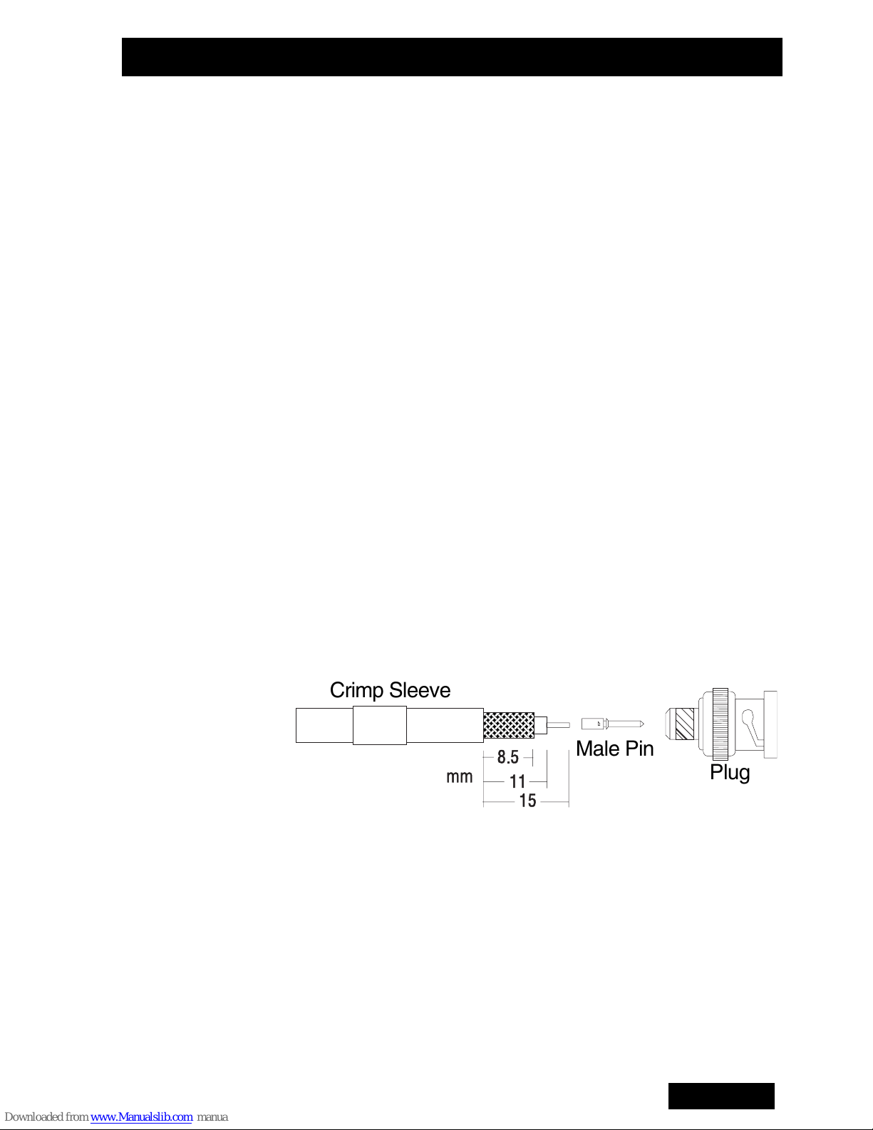
2 Terminate the free end of the cable with the BNC
crimp plug supplied, as shown in Figure 6:
• Fit the crimp sleeve over the cable sheath.
• Trim the outer sheath from the cable to 15mm (see
Figure 6 below).
• Trim the braid to 8.5mm.
• Trim the dielectric to 11mm. (Take extreme care not to
‘nick’ the centre conductor with the trimming device.)
• Fit the male pin onto the centre conductor with the
shoulder pressed against the end of the dielectric.
• Crimp the male pin onto the centre conductor.
• Press the assembly firmly into the rear of the plug.
(Ensure that no braid gets trapped between the
dielectric and the inside of the plug.)
• Slide the crimp sleeve over the braid and press
against the shoulder of the plug.
• Crimp the crimp sleeve onto the braid and plug body.
Crimp Sleeve
aaaaaa
bbbbbb
aaaaaa
bbbbbb
Male Pin
Plug
Figure 6: Antenna Connector Assembly
English
23
Page 27
Installation
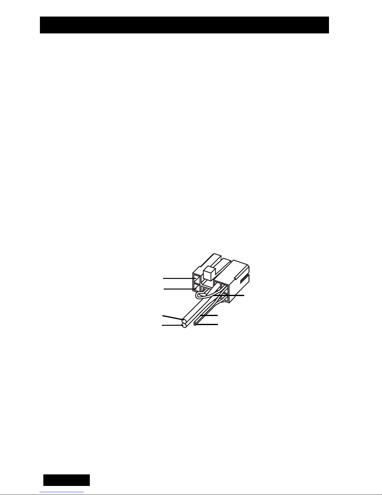
Wiring External Speaker
Some T2000
However it is possible to fit an external speaker if
required, by terminating a twin wire in the power
connector. To disable the internal speaker, cut the link
on the power connector as shown in Figure 7.
T2000
external speaker fitted. The power connector comes
pre-wired with the speaker cable.
Power
Supply
II models with no internal speaker must have an
Ignition
External
+13.8V
{
Ground
II models are fitted with internal speakers.
Internal Speaker Link
(cut to disable)
Ground
Live
External Speaker
}
Figure 7: Power Connector Wiring
Mount the external speaker in a convenient location
close to the operator. Run the free end of the speaker
wire to the speaker, and connect it to the speaker plug.
Power Cable
1 Disconnect the vehicle’s battery unless specifically
prohibited from doing so by the customer, vehicle
manufacturer, agent or supplier. In this event,
exercise extreme caution throughout the installation
and fit the fuses only when the installation is
complete.
Caution: Always disconnect the radio’s power lead
before connecting a second battery or using power
from another vehicle (e.g. when “jump-starting” the
vehicle).
2 Determine where the battery leads will be routed.
24
English
Page 28

Installation
3 Cut the negative and the positive wires where the in-
line crimp fuse holders will be placed (as close to the
battery as practicable).
4 Insert each end of the negative wire into one of the in-
line crimp fuse holders and crimp them to force the
metal contacts onto the wires. Terminate the wire at
the battery earth.
5 Repeat Step 4 for the positive wire and terminate it at
the positive terminal of the battery.
Caution: Prevent the power wires chafing on any
metal parts.
Note: T2000II radios are designed to operate from a
nominal 12V negative earth supply, and require
currents of up to 8A. (The radios will tolerate a supply
voltage range of 10.8V to 16.0V). In vehicles with a
24V electrical system (e.g. many trucks), it is
essential to provide a suitably rated 24/12V converter
to isolate the radio from the battery and protect it
against excessive voltages.
6 If the economiser is to be controlled by the ignition
line, terminate a wire in the power connector and
connect the ‘ignition’ wire to a +12V supply which is
live only when the vehicle’s ignition is switched ‘On’.
English
25
Page 29

Installation
External Wire
(Horn/Hush/
Emergency)
Remote Control
Head Option
The T2000
horn, radio or a hidden switch:
1 Terminate a suitable length of wiring in the “external”
port of the power connector.
2 Run the free end of the external wire from the power
connector to the appropriate vehicle wiring.
The option’s interface is usually configured to switch or
be switched in the ground state. Confirm the exact
operation in the documentation supplied with the
interface unit.
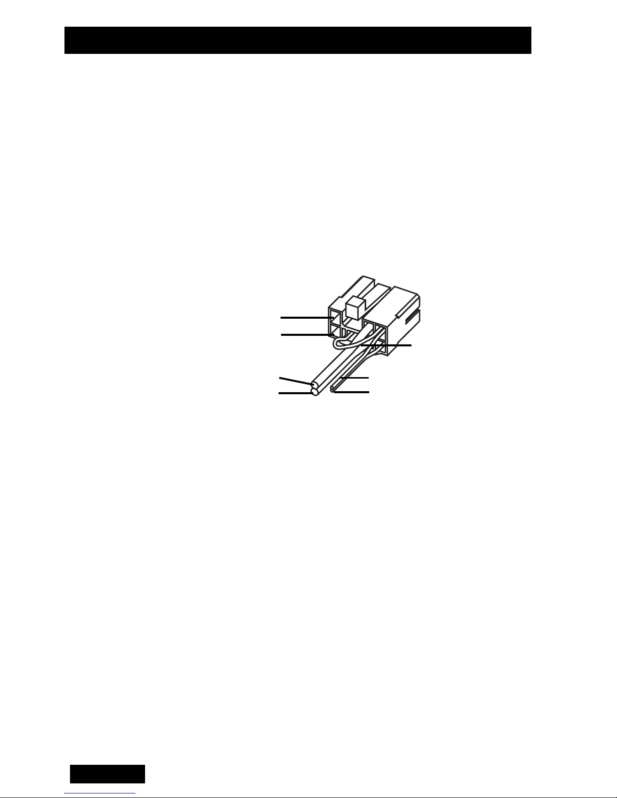
The control head of some T2000
supplied ready for mounting remotely from the radio
chassis. In this case the control head should be located
away from direct sunlight, and the cable connecting it to
II can be configured to operate the vehicle’s
II models may be
the radio should be routed away from the antenna with
care taken to ensure that the cable will not be subject to
damage.
If it is necessary to run the cable through a bulkhead or
similar obstruction, you may unplug the cable from the
control head as follows (see also figure 8):
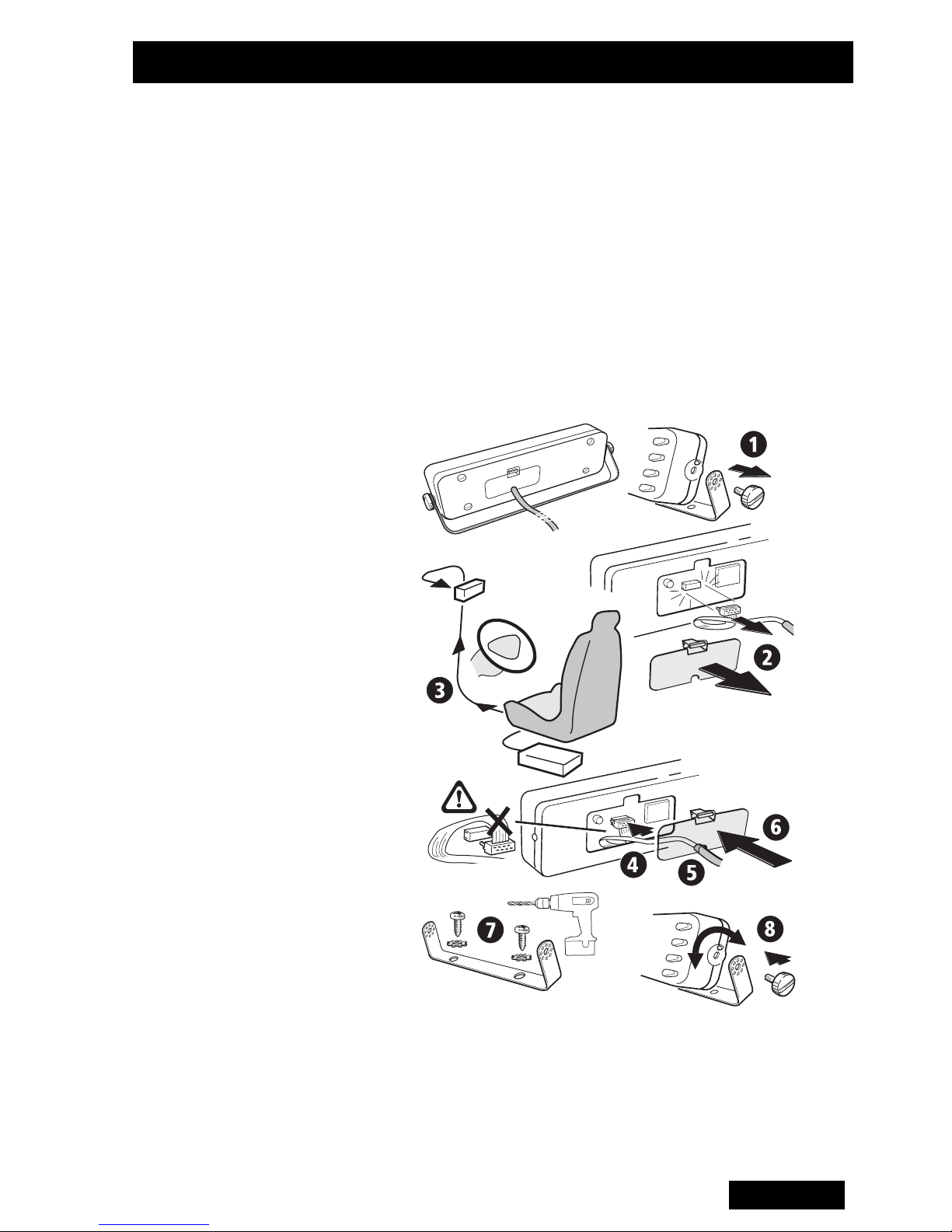
1 Unscrew the rear of the control panel and lift off the
rear cover, taking care not to lose the two nuts located
on each end.
2 Disconnect the red connector from the printed circuit
board socket to free the cable.
3 Route the cable as required, fitting grommets where
necessary to prevent chafing of the cable insulation.
4 Fit the red connector to the printed circuit board
socket – the connector is shaped so that it can be
fitted in the correct orientation only.
26
English
Page 30
Installation
5 Refit the cable to the cable clamp on the rear cover
and slip the two nuts into the receptacles at each end
of the rear cover.
6 Refit the rear cover and replace the cover screws,
tightening them carefully. Do not overtighten the
screws.
The control head can now be installed as follows:
7 Mount the bracket for the control panel on a flat
surface using the self-tapping screws supplied.
8 Place the control head in the bracket, position it for a
Figure 8: Remote Control Head Option
good viewing angle, and fit the 2 screws to secure it in
place.
English
27
Page 31

Installation
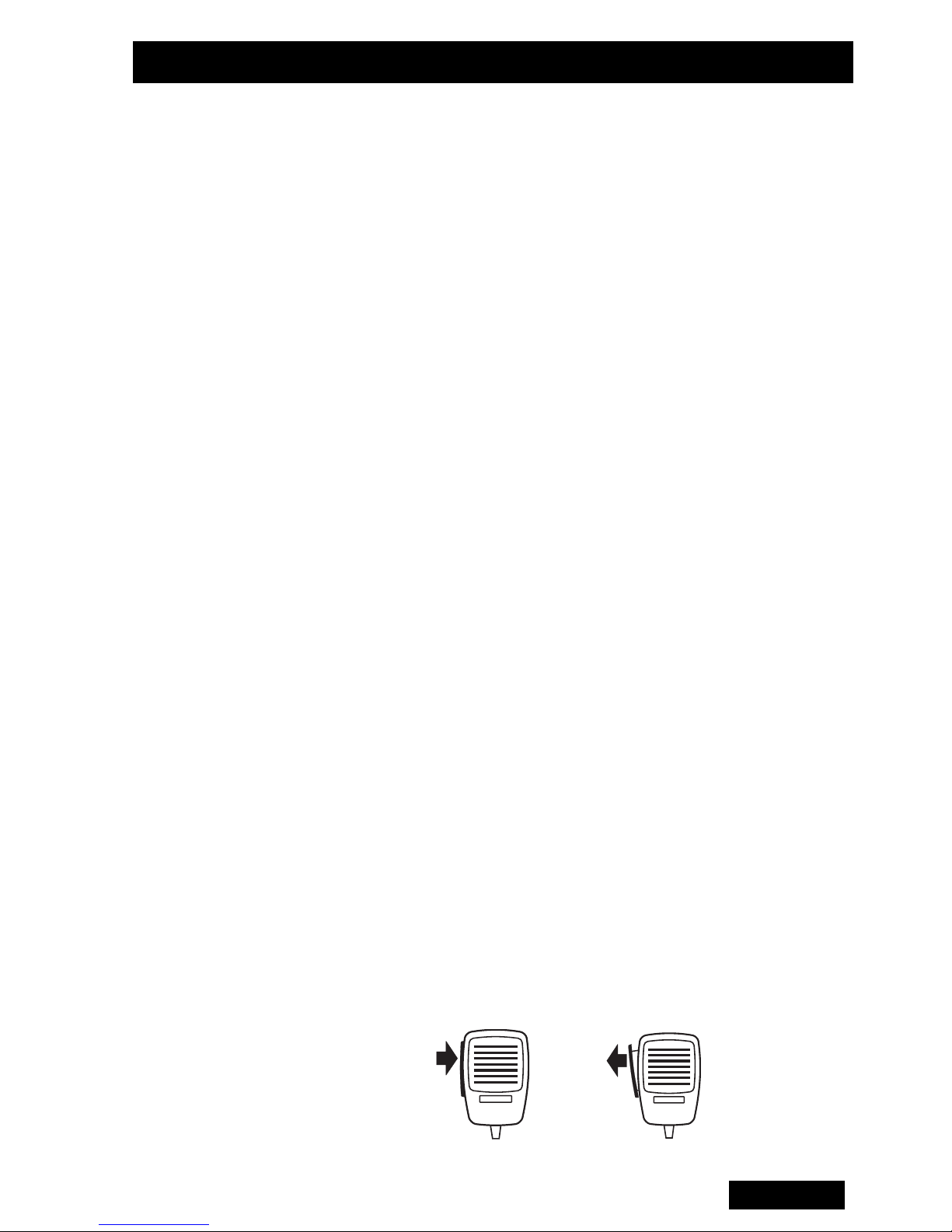
Microphone
Clip
Installation
Checks
The microphone clip must be earthed (to the negative
supply line) if hookswitch control of monitoring, scanning
or call termination is to operate. Refer to the radio’s
operating instructions to confirm requirements.
Ensure that the microphone clip is mounted in a position
where the microphone PTT key cannot be inadvertently
activated or jammed on.
1 Plug the microphone into the socket on the lower left-
hand corner of the radio’s front panel. Push the cable
grommet into the rectangular aperture in the panel.
2 Insert the fuses into the power lead.
3 Switch on the radio and confirm that it is operational.
4 Connect an in-line power meter between the radio
and the antenna and measure the forward and
reflected power levels. Less than 1W should be
reflected for 25W forward power. If this is not
achieved, check the installation – including antenna
length.
5 Make a call to another party on the radio (as
described in the operating instructions).
28
English
Page 32

T2030
T2035
II
II
Bedienungsanleitung
Deutsch
29
Page 33

Sicherheitsvorkehrungen
• Wenn keine Metallabschirmung zwischen Ihnen und
der Antenne vorhanden ist, müssen Sie sich
mindestens 20 cm von der Antenne entfernt befinden,
während das Funkgerät sendet.
• ACHTUNG: SCHALTEN SIE DAS FUNKGERÄT AN
TANKSTELLEN AUS.
• ACHTUNG: SCHALTEN SIE DAS FUNKGERÄT IN
DER NÄHE VON EXPLOSIONSGERÄTEN AUS
(z.B. in einer Mine, in der Sprengtechnik verwendet
wird).
• Das Benutzen eines Handmikrofons oder eines
Funkgerätes während des Führens eines Fahrzeuges
ergibt sich aus den entsprechenden Gesetzen in
Ihrem Land. Stellen Sie bitte sicher, daß Sie in
Übereinstimmung mit den Gesetzen Ihres Landes
handeln.
EN60950 Konformität
Dieses Radio entspricht der Norm EN60950 der
Europäischen Union, wenn es bei dem vorgesehenen
Arbeitszyklus von bis zu 33 %, d. h. zwei Minuten
Senden und vier Minuten Empfang, sowie bei einer
Umgebungstemperatur von maximal 30 °C betrieben
wird. Der Betrieb außerhalb dieser Grenzwerte kann zu
einem Anstieg der Außentemperatur des Radios über
die durch die Norm EN60950 vorgeschriebene
Temperatur führen.
Um die Konformität mit der Norm EN60950 zu
gewährleisten, muss das Radio so aufgestellt werden,
dass der Benutzer nicht in Kontakt mit dem Kühlblock
des Radios kommen kann.
30
Deutsch
Page 34

Informationen zur Übereinstimmung
Gesundheit,
Sicherheit und
elektromagnetische
Verträglichkeit in
Europa
In der Europäischen Union unterliegen
Funkanlagen und Telekommunikationsendeinrichtungen der Richtlinie 1999/5/EG, auch als R&TTERichtlinie (Radio Equipment & Telecommunications
Terminal Equipment) bekannt. Diese Richtlinie
schreibt sowohl den Gesundheitsschutz und die
Sicherheit der Benutzer als auch die elektromagnetische Verträglichkeit der Einrichtung vor.
Verwendungszweck des Produkts
Bei dem Produkt handelt es sich um einen UKWTransceiver. Er ist für den Funkverkehr in privaten
Mobilfunkservices (PMR) bzw. öffentlichen
Mobilfunkservices (PAMR) vorgesehen.
Wichtiger Hinweis: Dieses Produkt kann auf
Frequenzen und Emissionen programmiert
werden, die evtl. unzulässig sind. Deshalb muss
vor dem Gebrauch dieses Produktes eine
Genehmigung eingeholt werden. Alle
Genehmigungsbedingungen müssen eingehalten
werden. Einschränkungen können sich auf die
Senderleistung, die Betriebsfrequenz, den
Kanalabstand sowie die Emission beziehen.
Übereinstimmungserklärung
Kurze Übereinstimmungserklärungen befinden
sich auf Seite 2.
Die förmliche Übereinstimmungserklärung kann
von der folgenden Webseite heruntergeladen
werden: http://eudocs.taitworld.com/.
Eine unterschriebene und datierte Papierkopie der
Übereinstimmungserklärung erhalten Sie von Tait
Europe Ltd.
Deutsch
31
Page 35

Informationen zur Übereinstimmung
Elektromagnetische
Verträglichkeit in
europäischen
Fahrzeugen
Grenzwerte für
Hochfrequenzstrahl
ung in den USA
In der Europäischen Union unterliegen
Funkanlagen der Richtlinie 72/245/EWG in der
Fassung 95/54/EG. Die Vorgaben dieser Richtlinie
beziehen sich auf die elektromagnetische
Ver träglichkeit von elektrischen und elektronischen
Ausrüstungen in Kraftfahrzeugen.
Wichtiger Hinweis: Um den Anforderungen der
Richtlinie 72/245/EWG in der Fassung 95/54/EG
zu entsprechen, müssen bei der Installation dieses
Produkts in ein Fahrzeug die mitgelieferten
Anweisungen sowie ggf. die Vorgaben des
Fahrzeugherstellers beachtet werden.
Abschnitt 15 der FCC Vorschriften schreibt zum
Schutz gegen Störungen beim Radio- bzw.
Fernsehempfang Grenzwerte für
Zusätzliche
Informationen
Hochfrequenzstrahlung für elektronische
Ausrüstung vor.
Dieses Gerät entspricht Abschnitt 15 der FCC
Vorschriften. Sein Einsatz unterliegt der
Bedingung, dass es keine schädlichen
Interferenzen verursacht.
Wichtiger Hinweis: Änderungen und Umbauten
des Gerätes, die nicht ausdrücklich von Tait
Electronics Ltd genehmigt wurden, können dazu
führen, das der Einsatz des Gerätes gesetzwidrig
ist.
Weitere Produktangaben sowie Angaben zu den
Geschäftsstellen von Tait finden Sie unter:
http://www.taitworld.com/.
32
Deutsch
Technische Unterstützung finden Sie unter:
http://support.taitworld.com/.
Page 36

Inbetriebnahme
Einleitung Die Bündelfunk-Geräteserie T2030/35
folgende Rufarten verwendet werden:
• Sprechrufe an Funkgeräte Ihrer Flotte und anderer
Flotten
• Sprechrufe in das öffentliche Telefonnetz
• Statusmeldungen an ein vorprogrammiertes
Zielfunkgerät (z.B. an Ihre Zentrale).
Gerätekonfiguration
Einschalten
des Funkgerätes
Das T2030/35
es anwenderspezifisch konfiguriert werden kann, um
den Anforderungen Ihrer Flotte gerecht zu werden. Aus
diesem Grund können sich einige der in dieser
Anweisung beschriebenen Funktionsmerkmale von
denen Ihres Funkgerätes unterscheiden.
Sollte eine Funktion nicht wie beschrieben ausgeführt
werden können, wenden Sie sich bitte an Ihren TAITFachhändler.
II ist mikroprozessorgesteuert, so daß
II kann für
Benutzen
des
Mikrofons
und der
Sendetaste
Schalten Sie das Funkgerät durch Drehen des Ein/Ausund Lautstärkereglers ein. Bei Empfang des ersten
Rufes kann die gewünschte Lautstärke genau
eingestellt werden.
Die LED SVC (Service) leuchtet gewöhnlich nach
wenigen Sekunden auf. Falls sie nicht aufleuchtet,
befinden Sie sich vielleicht nicht im Empfangsbereich
Ihres Sendenetzes.
Mit der Sendetaste wird das Funkgerät während eines
Rufes zwischen Empfangs- und Sendemodus
geschaltet.
Drücken Sie die Sendetaste, um zu sprechen. Lassen
Sie die Sendetaste los, um zu hören.
Während eines Sendevorganges leuchtet die LED TX.
Deutsch
33
Page 37

Rufaussendung
Dieser Abschnitt beschreibt die Auswahl eines
Rufempfängers und den Verbindungsaufbau.
T2030
II
Alle im T2030II vorhandenen Rufarten sind Voreinstellungen, die während der Geräteprogrammierung
getroffen wurden. In Abhängigkeit von der jeweiligen
Geräteprogrammierung kann das T2030
verschiedene Empfänger in Ihrem Sendenetz und in
das öffentliche Telefonnetz aussenden.
Ein Ruf wird ausgesendet, indem eine der Ruftasten
C1
( to ) oder die Dispatchertaste ()
gedrückt wird. Die Dispatchertaste ( ) wird
zumeist für eine Rufaussendung an Ihre Zentrale
benutzt.
Die für die Geräteprogrammierung verantwortliche
Person wird Ihnen die Rufempfänger mitteilen, die
jeder Taste zugeordnet wurden.
C4
II Rufe, an
T2035
II
Aussenden eines Rufes vom T2035II :
1 Benutzen Sie die numerischen Tasten, um die
gewünschte Rufnummer einzugeben.
2Drücken Sie die Ruftaste ( ), um den Ruf
auszulösen.
Die für die Geräteprogrammierung verantwortliche
Person wird Ihnen mitteilen, welche voreingestellten
Rufnummern und persönlichen Kennungsnummern
verwendet werden müssen, um verschiedene
Empfänger anzurufen.
Es sind bis zu drei verschiedene Rufarten in
Abhängigkeit von der Geräteprogrammierung möglich:
• Voreingestellte Rufe an verschiedene Empfänger;
• Direkte Rufe an Teilnehmerkennungen in Ihrem
Sendenetz;
• Gruppenrufe an zwei oder mehrere Kennungen.
34
Deutsch
Page 38
oder
Rufempfang
Die Anruftöne, die Sie bei einem eingehenden Ruf
hören, können variieren. Das ist von der
Geräteprogrammierung und der Art des genutzten
Sendenetzes abhängig.
Die beiden Arten der Anruftöne sind unten zusammen
mit Anweisungen dargestellt:
Anrufton: Beantworten:
Dieses ist ein direkter Ruf. Wenn die LED
Zwei Töne
Ein einzelner Ton
GO oder leuchtet, nehmen Sie das Mikro-
fon und antworten Sie dem Anrufer.
Dieses ist eine Rufanfrage. Entweder:
Ein Klingelton
1 Nehmen Sie das Mikrofon aus der
Halterung.
Anruferidentifizierung
T2030
T2035
II
II
2 Warten Sie, während das Funkgerät die
Verbindung aufbaut.
3 Antworten Sie, wenn die LED WAIT
erlischt und die LED GO aufleuchtet.
Oder: Drücken Sie die Löschtaste
( ), um den Ruf abzuweisen.
Wenn der Ruf von einem Teilnehmer ausgesendet
wurde, dessen Kennung als eine Voreinstellung in
Ihrem Funkgerät gespeichert ist, wird diese voreingestellte Kennung wie folgt angezeigt:
Die LED über der entsprechenden, mit einer
Voreinstellung versehenen Ruftaste leuchtet auf.
Die voreingestellte Nummer des Anrufers erscheint im
Anzeigefeld. Das T2035
II kann folgende Informationen
anzeigen:
Bei einem Anruf:
Aus Ihrer Flotte
Aus einer anderen Flotte
Aus dem öffentlichen
Fernsprechnetz Identifizierbar
II
Das T2030/35
zeigt an:
die Flottenkennung des Anrufers
.1.
.2. oder .3.
.4.
Deutsch
35
Page 39

Rückrufe
Benutzen Sie die unten beschriebenen Speicherfunktionen, um Verbindungen erneut aufzubauen und
Teilnehmer zurückzurufen, dessen Anrufe unbeantwortet blieben.
Rückruf Wenn ein von Ihnen empfangener Ruf beendet wird,
speichert das Funkgerät die Nummer des Anrufers.
Wahlwiederholung
Beim T2030
taste, und beim T2035
Nummer oder Kennung des Anrufers im Anzeigefeld.
Drücken Sie die Rückruftaste ( ) (T2030
die Ruftaste ( ) (T2035
zurückzurufen. Warten Sie bis die LED GO aufleuchtet, bevor Sie mit der Konversation beginnen.
In Abhängigkeit von der Gerätprogrammierung können
Sie einen Rückruf auch durch ein kurzes Drücken der
Sendetaste auslösen.
Die von Ihnen zuletzt gewählte Nummer ist ebenfalls im
Funkgerät gespeichert. Drücken Sie die Sende-
taste, um diesen Ruf erneut auszusenden.
Wenn sich das Funkgerät im Rückrufmodus befindet,
II leuchtet die LED über der Rückruf-
II blinkt die voreingestellte
II ) oder
II ), um den Teilnehmer
drücken Sie vor der Wahlwiederholung die Löschta-
ste, um die gespeicherte Rückrufkennung zu löschen.
Anrufspeicherung
nur T2035
36
Deutsch
II
In Abhängigkeit von der Geräteprogrammierung des
T2035
kennungen speichern.
Drücken Sie für ungefähr eine Sekunde die Speicher-
taste ( ) und die Dispatchertaste ( ), um die
Anruferliste aufzurufen. Die LED über der Speicher-
taste leuchtet auf. Drücken Sie erneut die Dispatcher-
taste, um die Liste zu verlassen.
II kann es bis zu 20 unbeantwortete Ruf-
Page 40

Rückrufe
Nach dem Aufrufen der Anruferliste drücken Sie die
Speichertaste ( ), um durch die Liste mit den
Kennungen zu blättern.
Um eine der gespeicherten Kennungen zurückzurufen,
drücken Sie bei Anzeige der entsprechenden Kennung
die Sende- oder Ruftaste. Eine Kennung wird aus der
Liste gelöscht, indem die Löschtaste ( ) betätigt
wird.
Zusätliche Informationen
Statusrufe Statusrufe ermöglichen den schnellen Austausch
einfacher Meldungen, ohne daß eine Sprech-
verbindung erforderlich ist. In das Funkgerät können
solche Meldungen wie “Unterwegs” oder “Mittag”
programmiert werden.
Notrufe Das Funkgerät muß an einen versteckten Notruf-
schalter angeschlossen und für das Aussenden von
Notrufen programmiert sein.
Ein Notruf wird wie folgt ausgesendet:
• Betätigen Sie den versteckten Notrufschalter.
• Das Funkgerät sendet einen Notruf an einen
vorprogrammierten Teilnehmer.
• Während eines Notrufes schaltet das Funkgerät den
• Sie können das Funkgerät zurücksetzen, indem Sie
Dispatcherbetrieb
Das T2030/35
werden, indem es auf das separat lieferbare Netzgerät
T2008 montiert wird. Das Funkgerät muß für einen
Dispatcherbetrieb programmiert werden.
Sendemodus intern ein und aus, so daß Aktivitäten
in der näheren Umgebung des Funkgerätes
überwacht werden können.
es aus- und wieder einschalten.
II kann als Dispatchergerät verwendet
Deutsch
37
Page 41

Zusätzliche Informationen
Stromsparmodus
Maximale
Sendezeit
Wartung Das T2030/35
Das Funkgerät kann in Abhängigkeit von der
Geräteprogrammierung nach einer vorbestimmten Zeit
der Inaktivität einen Stromsparmodus aktivieren, der
die Hintergrundbeleuchtung des Bedienteils und des
Anzeigefeldes dimmt oder ausschaltet.
Das Funkgerät schaltet bei einer gültigen Aktivität auf
dem ausgewählten Kanal oder bei Betätigung der
Sendetaste oder einer Bedienteiltaste in den vollen
Betriebsmodus zurück.
Das T2030/35
miert sein, der die Länge von Übertragungen begrenzt.
Das Funkgerät meldet sich mit einem Warnton, bevor
die Übertragung unterbrochen wird.
II kann mit einem Zeitgeber program-
II muß nicht regelmäßig gewartet
Fehlersuche
Informationsco
des für Anrufe:
werden. Es muß nur sichergestellt werden, daß die
Antenne, alle Kabel, Verbindungen und Anschlüsse
korrekt installiert und nicht beschädigt sind.
Wenn keine der LED’s am Bedienteil nach dem
Einschalten des Funkgerätes aufleuchtet, ist
wahrscheinlich die Stromzufuhr zum Funkgerät
unterbrochen. Überprüfen Sie alle Kabel, Sicherungen
und Anschlußverbindungen zwischen der Batterie und
dem Funkgerät.
Sollte kein Fehler entdeckt werden, wenden Sie sich
an Ihren TAIT-Fachhändler.
:
Informationscodes
“0. .1” blinkend System ist besetzt
T2030/35
II
“0. . 2” blinkend Angerufener Teilnehmer nicht erre-
“0. . 3” blinkend Nummer nicht erreichbar
“0. . 4” blinkend Angerufener Teilnehmer besetzt
38
Deutsch
ichbar
Page 42

Geräteentnahme aus dem Fahrzeug
Geräteentnahme
aus der
Halterung
Sie können das Funkgerät aus Gründen der Sicherheit
aus dem Fahrzeug entnehmen. Das Funkgerät kann
unter Benutzung des Kunststoffschlüssels aus der
Halterung wie folgt entnommen werden:
1 Schalten Sie das
Funkgerät aus.
2Führen Sie den
Kunststoffschlüssel in
den Schlitz neben
dem Lautstärkeregler
ein (siehe Abbildung).
3 Ziehen Sie das Funkgerät aus der Halterung.
4 Ziehen Sie das Antennenkabel und die anderen
Anschlüsse an der Rückseite des Gerätes ab.
5 Entnehmen Sie das Funkgerät.
Deutsch
39
Page 43
Montageanleitung
Bestandteile
des Funkgeräts
T2000
II
Das Funkgerät T2000II sollte enthalten sein:
• Funkgerät T2000
• Mikrofon
• Kunststoffschlüssel / Halterung
• Lautsprecher / 4 Ohm (nur für Geräte ohne internen
Lautsprecher)
Montage Bausatz:
• Zweiwegstecker (1)
• Steckerfassung (2)
• 10A 12V Auto-
Stecksicherung (2)
• Sicherungshalter (2)
II
• Schneidschrauben (4)
• Vibrationsfeste
Unterlegscheiben (4)
• Mikrofonhalterung / Bausatz (1)
• Abgesetztes Bedienteil /
Bausatz (nur für T2020
T2040
II)
II und
Empfohlenes
Montagewerkzeug
40
Deutsch
• Handbohrmaschine
• Zentrierkörner
• Bohrer: 4 mm für Schneidschrauben oder 6 mm für
Durchsteckschrauben und Muttern
• Schraubendreher (“Pozidriv”)
• Crimpzange
• Durchgangsleistungsmeßgerät auf der
Betriebsfrequenz des Funkgerätes
• Hammer
Abbildung 1: Bestandteile des Funkgeräts T2000
II
Page 44

Montageanleitung
Montagevorbereitung
Sicherheit Überprüfen Sie, ob die von Ihnen gewählte Montageanord-
Um eine störungsfreie und zügige Montage zu garantieren,
entscheiden Sie, bevor Sie mit der Montage am Fahrzeug
beginnen, wo die Antenne, das Funkgerät und das Zubehör
installiert werden soll.
Die T2020
Tastatur sind sowohl mit aufgesetztem als auch abgesetztem
Bedienteil lieferbar. Das ermöglicht es Ihnen, das Funkgerät
z.B. im Kofferraum und das Bedienteil an einem für den Fahrzeugführer geeigneten und leicht zu erreichenden Ort im
Fahrgastraum zu montieren. Ein Funkgerät mit einem aufge-
setzten Bedienteil kann für eine Unterbordmontage verwendet werden. Lesen Sie das Wartungshandbuch M2000, wenn
Sie genauere Informationen benötigen.
nung für das Funkgerät und dessen Zubehör die Fahrzeugin-
II und T2040II Modelle mit alphanumerischer
sassen nicht gefährdet. Ein hoch gelegener Einbauplatz im
Fahrgastraum ist nicht empfehlenswert. Überprüfen Sie, ob
das Funkgerät bequem bedient werden kann, wenn der
Sicherheitsgurt angelegt wurde.
Achtung: Um Störungen in der Fahrzeugelektrik und -
elektronik (z.B. Zündung, ABS usw.) zu vermeiden, sollten
das Funkgerät, die Antenne und die dazugehörigen Kabel
entfernt von diesen Einrichtungen und deren Verkabelungen
installiert werden.
Vermeiden Sie es, das Funkgerät sowohl an einen Platz mit
einer schlechten Luftzirkulation (z.B. in Handschuhfächern)
oder an einen Platz, der sich in unmittelbarer Nähe der Fahrzeugbelüftung bzw. Fahrzeugheizung befindet, zu montieren.
Überprüfen Sie auch, ob der Einbauplatz eine genügend
große und flache Oberfläche bietet, damit die Halterung bei
der Montage nicht verbiegt.
Um die Konformität mit der Norm EN60950 zu gewährleisten,
muss das Radio so aufgestellt werden, dass der Benutzer
nicht in Kontakt mit dem Kühlblock des Radios kommen kann.
Deutsch
41
Page 45

Montageanleitung
Zerlegen der
Halterung
1 Um das Funkgerät aus der Halterung zu entfernen,
führen Sie den mitgelieferten Kunststoffschlüssel
ganz in den Schlitz vorne links am Gerät ein. Das
Gerät kann nun aus der Halterung gezogen werden.
Halterung
Gerät
Schlüssel
Abbildung 2: Gerät und Schlüssel
2 Zerlegen Sie die
Halterung, indem
Sie diese auf
eine feste
Unterlage legen
und mittels eines
Schraubendrehe
rs Druck auf eine
der mittleren
Plastikrippen
ausübe. Dadurch
werden auch die
Abbildung 3:
Zerlegen Sie die Halterung
anderen Plastikrippen auf dieser Seite aus den
Metallschlitzen gedrückt. Verfahren Sie auf den
gegenüberliegenden Seite genauso. Die
Metallabdeckung kann nun leicht abgehoben
werden.
Einbau Halten Sie die vorgebohrte Hälfte der Halterung an die
vorgesehene Position für das Funkgerät und benutzen
Sie die vier Halterungsbohrungen als Schablone für das
Markieren der Bohrlöcher. Stellen Sie sicher, daß wäh-
rend des Bohrens an den gewählten Positionen keine
Leitungen und Kabelbäume beschädigt werden.
42
Deutsch
Page 46
Montageanleitung
Körnen Sie die Bohrpunkte mit einem Zentrierkörner
an, und bohren Sie 4 mm Löcher für die Schneidschrauben oder 6 mm Löcher für Schrauben mit Muttern. Verringern Sie die Lochweite für Schneidschrauben, wenn
das Metall, auf dem die Halterung montiert wird, weniger als 1 mm stark ist.
Bohren Sie in der Nähe der Halterung alle erforderlichen Löcher, um die Kabel an das Funkgerät zu führen.
Versehen Sie diese Bohrlöcher mit geeigneten Gummitüllen.
Schrauben Sie die Metallabdeckung auf den gewählten
Einbauplatz, indem Sie die mitgelieferten Schneidschrauben (M5) mit einem Schraubendreher in die
Bohrlöcher drehen. (Sie können, wenn möglich, auch
Schrauben (M5) und Muttern verwenden.) Achten Sie
darauf, daß die Metallabdeckung beim Eindrehen der
Schrauben nicht verbiegt.
Abbildung 4 - Einbau
Deutsch
43
Page 47
Zusammenbau
der Halterung
Montageanleitung
Abbildung 5: Zusammenbau der Halterung
Installation der
Antenne
1 Wenn die Antenne für einen einwandfreien Betrieb
auf einer ebenen Oberfläche montiert werden muß,
ist es empfehlenswert, diese in einer der
dargestellten Positionen zu installieren.
1= bevorzugt 4 = weniger empfehlenswer
Abbildung 6: Empfohlene Antennenpositionen
2 Wenn die Antenne nicht auf einer ebenen Oberfläche
montiert werden kann, sollten Sie die
Montageanleitungen beachten, die mit der Antenne
geliefert werden.
3 Montieren Sie die Antenne so, daß sich der
menschliche Körper, während das Funkgerät sendet,
mindestens 20 cm entfernt von der Antenne befindet,
es sei denn, eine Metallabschirmung (z.B. ein
Metalldach), die wenigstens 0,3 m2 groß ist (d.h. 0,55
m x 0,55 m), befindet sich zwischen Körper und
Antenne.
44
Deutsch
Page 48

Montageanleitung
a
a
a
a
aaaaaaaa
b
b
b
b
bbbbbbbb
4Schließen Sie ein Ende des Koaxialkabels an die
Antenne an. Ein geeignetes Koaxialkabel (50 Ohm) guter
Qualität ist z.B. RG58 oder UR76. Führen Sie das freie
Ende des Koaxialkabels zu dem Einbauplatz des
Funkgerätes und schneiden Sie es dann auf Länge,
indem Sie 200 mm bis 300 mm zur benötigten Länge
dazugeben.
5 Montieren Sie den mitgelieferten BNC-Stecker
folgendermaßen an das freie Ende des Koaxialkabels:
-Führen Sie die Metallhülse über den Kabelmantel.
- Isolieren Sie 15 mm vom äußeren Kabelmantel ab.
- Schneiden Sie die Abschirmung (Geflecht) auf 8,5 mm.
- Schneiden Sie das Dielektrikum auf 11 mm. (Achten
Sie insbesondere darauf, daß Sie den Innenleiter dabei
nicht beschädigen.)
- Stecken Sie den Stift auf den Innenleiter, so daß das
Ende des Stiftes mit dem Dielektrikum abschließt.
- Crimpen Sie den Stift mittels der Crimpzange auf den
Innenleiter.
-Drücken Sie das Kabel mit der Metallhülse und dem
Stift fest in die hintere Öffnung des Steckers. (Stellen
Sie sich sicher, daß keine Fasern des Kupfergeflechts
zwischen Masse und Antennenpol eingeklemmt
werden.)
- Schieben Sie die Metallhülse über die Abschirmung
(Geflecht), so daß das vordere Ende der Hülse mit
dem Stecker abschließt.
- Crimpen Sie die Metallhülse mittels der Crimpzange
auf die Abschirmung (Geflecht) und das hintere
M203X-00-050 45
Steckerteil.
Metallhülse
Abbildung 7: Montage des BNC-Steckers
aaaaaa
bbbbbb
aaaaaa
bbbbbb
Stift
Stecker
Deutsch
Page 49
Montageanleitung
r
Verkabelungen Abgesetzter Lautsprecher
Einige T2000
Lautsprecher ausgerüstet. Es ist allerdings möglich,
einen abgesetzten Lautsprecher an diese Geräte anzuschließen, falls das gewünscht wird.
Der integrierte Lautsprecher kann außer Funktion
gesetzt werden, indem die Verbindung am Anschluß-
stecker getrennt, d.h. zerschnitten wird. Ein zweiadriges
Kabel sollte an den Stecker an die Anschlüsse ‘Masse’
und ‘Signal’ angeschlossen werden.
Die T2000
cher erfordern die Montage eines abgesetzten Laut-
sprechers. Der Stecker ist bei diesen Geräten für den
Anschluß eines abgesetzten Lautsprechers ausgelegt
und das Lautsprecherkabel ist an den Stecker angeschlossen.
II Modelle sind mit einem integrierten
II Funkgeräte ohne integriertem Lautspre-
Stromversorgung
Montieren Sie den abgesetzten Lautsprecher in der
Nähe des Fahrersitzes. Führen Sie das
Lautsprecherkabel zum Lausprecher und schließen Sie
es an.
Stromkabel
1 Trennen Sie die Stromzufuhr von der
Zündung
Extern
+13.8V
{
Masse
Abbildung 8: Belegung des Anschlußsteckers
Fahrzeugbatterie. Falls Ihnen dieses vom Kunden,
dem Fahrzeughersteller oder -händler untersagt ist,
weil sich spezielle elektronische Einrichtungen im
Masse
Signal
Verbindung fur internen
Lautsprecher
(trennen wenn nötig)
Externer Lautspreche
}
46
Deutsch
Page 50

Montageanleitung
Fahrzeug befinden, müssen Sie bei der Installation
äußerst vorsichtig und sorgfältig vorgehen.
Achtung: Bitte trennen Sie immer die
Funkgeräteanschlußkabel ab, bevor Sie eine zweite
Batterie anschließen oder z.B. “Starthilfe” durch ein
zweites Fahrzeug machen.
2 Bestimmen Sie die Verlegung des Batteriekabels.
3 Trennen Sie die Minus- und Plus-Seite des Kabels
dort auf, wo die Sicherungshalter eingecrimpt
werden sollen. (so nah wie möglichzur Batterie).
4 Stecken Sie den Sicherungshalter in die Masse-
Leitung des Batteriekabels ein und vercrimpen Sie
die Leitung mit dem Halter. Schließen Sie die Leitung
und den Minuspol der Batterie an.
5 Tun Sie dasselbe mit der Plusleitung und verbinden
Sie diese mit dem Pluspol der Batterie.
Achtung: Achten Sie darauf, daß die Stromkabel
nicht auf Metallteilen scheuern.
Hinweis: Die Funkgeräte der Geräteserie T2000II
sind für eine Nennspannung von 12 Volt ausgelegt
und benötigen eine Stromstärke bis zu 8 Ampere.
Die Funkgeräte können in einem Spannungsbereich
von 10,8 Volt bis 16,0 Volt betrieben werden.
Fahrzeuge, die mit einer Nennspannung von 24 Volt
arbeiten (viele Lastkraftwagen), benötigen einen
Spannungswandler (24/12V) (z.B. Tait T2007).
6 Schließen Sie das “Zündstromkabel” an eine positive
Spannungsquelle an, die nur dann eine Spannung
von 12 Volt aufbaut, wenn die Fahrzeugzündung
eingeschaltet wird. (Dieser Anschluß wird nur für den
Stromsparbetrieb benötigt.)
Deutsch
47
Page 51

Montageanleitung
Externe Leitung
(Autohupe/
Stummschaltung/Notruf)
Abgesetztes
Bedienteil
Das Funkgerät T2000
eine Autohupe, ein Autoradio oder mit einer versteckten
Notruftaste verbunden werden kann.
1 Verbinden Sie ein genügend langes Kabel mit der
“external” Buchse auf dem Batteriestecker.
2 Verbinden Sie dann das freie Ende dieses Kabels mit
der entsprechenden KFZ-Verdrahtung.
Diese Schnittstelle wird gewöhnlich so konfiguriert, daß
sie im aktivierten Zustand auf Masse schaltet oder
geschaltet wird. Ein optimaler Betrieb sollte mit Hilfe der
Anleitungen für die Schnittstelle erreicht werden.
Die Bedienteile für einige T2000
abgesetzte Bedienteile geliefert werden, so daß sie ent-
fernt vom Funkgerät installiert werden können. Das
II wird so installiert sein, daß es
II Modelle können als
abgesetzte Bedienteil sollte so installiert werden, daß es
keiner direkten Sonnenstrahlung ausgesetzt ist, und
das Verbindungskabel sollte entfernt von der Antenne
zum Funkgerät geführt werden. Achten Sie darauf, daß
das Kabel bei der Verlegung nicht beschädigt wird.
Falls es notwendig sein sollte, das Kabel durch eine
Trennwand oder eine ähnliche Versperrung im Fahr-
zeug zu führen, können Sie das Kabel vom Bedienteil
folgendermaßen entfernen:
1Lösen Sie die vier Schrauben auf der Rückseite des
Bedienteils und entfernen Sie die Rückabdeckung
des Bedienteils und achten Sie dabei darauf, daß die
beiden Muttern, die sich an jeder Seite der Rückab-
deckung befinden, nicht verlorengehen.
2 Ziehen Sie den roten Anschlußstecker aus der
Buchse auf der Leiterplatte, um das Kabel zu
lösen.
3 Verlegen sie das Verbindungskabel wie gewünscht
und setzen Sie notwendige Gummihülsen auf, um
scheuern an der Karosserie zu vermeiden.
48
Deutsch
Page 52

Montageanleitung
4 Verbinden Sie den roten Konnketor mit der Fassung
auf der Platine - der Konnektor hat eine Führung,
sodaß er nur richtig aufgesetzt werden kann.
5 Stecken Sie das Kabel in die Kabelklemme an der
Rückseite des Bedienteils und stecken Sie die zwei
Muttern in ihren Sitz auf jeder Seite der Rückabdek-
kung.
6 Setzen Sie die Rückseite wieder auf und schrauben
Sie sich vorsichtig fest. Überdrehen Sie die Schrau-
ben nicht.
Installieren Sie nun das Bedienteil wie folgt:
7 Montieren Sie den Bügel für das Bedienteil mittels
der gelieferten Schneidschrauben auf eine ebene
Oberfläche.
Abbildung 9: Abgesetztes Bedienteil
Deutsch
49
Page 53

Montageanleitung
8 Stecken Sie das Bedienteil in den Bügel und drehen
Sie die zwei Schrauben ein (stellen Sie einen gutenBlickwinkel ein).
Mikrofonhalterung
Funktionsprü-
fung
Der Mikrofonanschluß in der Halterung muß an Masse
(an den Minusleiter) gelegt werden, wenn der
Mithörbetrieb über den Mikrofonschalter, der Suchlauf
oder die Rufbeendigung ausgeführt werden soll.
Achten Sie darauf, daß die Mikrofonhalterung an einem
Platz installiert wird, der eine unbeabsichtigte
Betätigung der Sprechtaste am Mikrofon ausschließt.
1 Stecken Sie den Mikrofonstecker in die
Mikrofonbuchse am Bedienteil, und drücken Sie die
Gummitülle in den rechteckigen Ausschnitt.
2 Setzen Sie die Sicherung in die
Batteriekabelhalterung ein.
3 Schalten Sie das Funkgerät ein und überprüfen Sie
den Betriebszustand. Bestimmte Anzeigen leuchten
auf.
4 Trennen Sie das Antennenkabel vom Funkgerät,
schließen Sie ein Leistungsmeßgerät zwischen
Funkgerät und dem Antennenkabel an und messen
Sie die Durchgangsleistung und die reflektierte
Leistung. Bei einer Durchgangsleistung von 6 W
sollte weniger als ca. 0,25 W reflektierte Leistung
auftreten. Falls dieser Wert nicht erreicht werden
sollte, überprüfen Sie die Installation, einschließlich
der Antennenlänge.
5Sie können die Funktionsprüfung beenden, indem
Sie einen Ruf an einen anderen
Teilnehmeraussenden.
50
Deutsch
Page 54

Deutsch
51
Page 55

52
Deutsch
Page 56

T2030
T2035
II
II
Guide de l’utilisateur
Français
53
Page 57

Précautions de sécurité
• Au cours de l’émission, aucune partie de votre corps
ne doit se trouver plus de quelques minutes à
proximité de l’antenne (dans une circonférence de 20
cm), à moins qu’un écran métallique ne les sépare.
• DANGER : ETEIGNEZ LA RADIO AVANT
D’ENTRER DANS LES STATIONS-SERVICES.
• DANGER : ETEIGNEZ LA RADIO A PROXIMITE
D’EXPLOSIFS (par exemple : dans les carrières
utilisant des techniques de minage).
• Certains pays interdisent l’utilisation d’un microphone
ou d’une radio tout en conduisant. Conformez-vous à
la loi en vigueur dans votre pays.
Conformité avec la norme EN60950
Cette radio satisfait à la norme européenne EN60950, à
condition qu'elle soit utilisée à une température
ambiante inférieure ou égale à 30°C et selon un cycle
de fonctionnement nominal de 33 % maximum, avec
deux minutes de transmission et quatre minutes de
réception. Le non-respect de ces limites peut entraîner
une augmentation de la température externe au-delà de
la limite de température prévue par la norme EN60950.
Pour assurer la conformité avec la norme EN60950, la
radio doit être montée dans une position où il est
impossible à l'utilisateur de toucher le dissipateur
thermique de la radio.
54
Français
Page 58

Informations sur la conformité
Conformité aux
normes sanitaires,
électromagnétique
s et de santé en
vigueur en Europe
Dans la Communauté européenne, les
équipements radio et de télécommunications sont
réglementés par la Directive 1999/5/CE visant les
équipements hertziens et les équipements
terminaux de télécommunications (R&TTE). Cette
directive prévoit notamment la protection et la santé
des utilisateurs, ainsi que la compatibilité
électromagnétique.
Usage prévu
Ce produit est un émetteur-récepteur radio FM. Il
est prévu pour la communication radio dans le
cadre de services de radiocommunications mobiles
privées (PMR) ou de services radiotéléphoniques
mobiles publics (PAMR).
Important: il est possible de programmer ce produit
pour des fréquences ou émissions qui peuvent
rendre son utilisation illicite. L'utilisation de ce
produit est soumise à licence. Tous les termes de la
licence doivent être observés. Des limitations
peuvent s'appliquer à la puissance de transmission,
la fréquence de fonctionnement, l'espacement des
canaux et l'émission.
Déclaration de conformité
Des déclarations de conformité succinctes sont
données page 3.
Vous pouvez télécharger la déclaration de
conformité officielle à partir du site http://
eudocs.taitworld.com/.
Vous pouvez obtenir un exemplaire de la
déclaration de conformité signé en vous adressant
à Tait Europe Ltd.
Français
55
Page 59

Informations sur la conformité
Compatibilité
électromagnétique
dans les véhicules
européens
Limitation des
émissions de
fréquences radio
aux USA
Dans la Communauté européenne, les
équipements radio installés dans des véhicules
automobiles sont réglementés par la Directive
72/245/CEE, modifiée par la Directive 95/54/CE.
Cette directive vise la compatibilité
électromagnétique des équipements électriques et
électroniques installés dans des véhicules
automobiles.
Important: pour que ce produit soit conforme à la
Directive 72/245/CEE (modifiée par la Directive
95/54/CE), son installation doit être réalisée
conformément aux instructions fournies et à celles
du fabricant du véhicule le cas échéant.
La partie 15 du règlement de la FCC restreint
l'émission RF des équipements électroniques afin
d'empêcher la perturbation de la réception des
services de radiodiffusion.
Informations
supplémentaires
Cet appareil est conforme à la partie 15 du
règlement de la FCC. Son fonctionnement n'est
autorisé qu'à condition qu'il ne cause pas de
brouillage préjudiciable.
Important: toute modification opérée sur cet
appareil sans l'approbation expresse de Tait
Electronics Ltd peut rendre son utilisation illicite.
Pour de plus amples informations sur ce produit et
pour les coordonnées des bureaux Tait, consultez
http://www.taitworld.com/.
Pour toute question d'ordre technique, consultez
http://support.taitworld.com/.
56
Français
Page 60
Mise en route
Introduction Le mobile radio T2030/35 Série
partagés vous permet de lancer les appels suivants :
• Appels voix (ou phonie) vers d’autres radios, au sein
de votre flotte ou vers des flottes extérieures
• Appels voix sur le réseau téléphonique
• Message d’état vers une destination préprogrammée
(par exemple, votre Base).
Variantes de
configuration
Votre T2030/35
peut ainsi être personnalisé pour satisfaire les besoins
de votre flotte. Pour cette raison, il est possible que
certaines caractéristiques décrites dans ce guide
fonctionnent différemment sur votre radio.
Si l’une des caractéristiques ne fonctionne pas comme
indiqué ci-dessous, veuillez consulter votre distributeur
II est contrôlé par microprocesseur. Il
II pour réseaux
Mettre la
radio en
marche
Utilisation
du micro et
du bouton
d’alternat
Ta i t.
Pour mettre la radio en marche, tournez le bouton
Marche/Arrêt et Volum e à environ un tiers de son
réglage maximal. Vous ajusterez le volume lors de la
réception de votre premier appel.
L’indicateur SVC (en service) s’allume normale-ment
dans les secondes qui suivent. Si ce n’est pas le cas, il
est possible que vous soyez hors de la zone de
couverture de votre réseau.
Le bouton d’alternat fait alterner la radio entre les
modes Emission et Réception.
Pour parler, appuyez sur l’alternat; relâchez-le pour
écouter. Au cours de la transmission, l’indicateur
d’émission (TX) s’allume.
Français
57
Page 61

Lancement d’un appel
La section suivante précise comment sélectionner la
destination d’appel et établir l’appel. Consultez la
section correspondant à votre type de radio.
T2030
II
Tous les appels accessibles sur le T2030II sont
préréglés par la personne en charge de la
programmation de votre radio (cette dernière vous
avisera des différentes destinations d’appel assignées
à chaque touche). Vous serez alors en mesure de
lancer des appels vers diverses destinations,
notamment vers d’autres radios sur votre réseau et
vers des numéros de téléphone.
Afin d’établir un appel, appuyez sur l’une des touches
d’appel ( à ), ou encore sur la touche Base
C1
C4
( ). Ces touches peuvent être programmées pour
différentes destinations d’appel. Généralement, la
touche Base ( ) est réglée de manière à contacter
la station de base ou l’opérateur radio.
T2035
II
Pour lancer un appel sur le T2035II :
1 Servez-vous des touches numériques afin d’entrer le
numéro à appeler.
2 Appuyez sur la touche Appel ( ) pour lancer
l’appel.
La personne chargée de la programmation de votre
radio vous renseignera sur les numéros d’appel
préprogrammés et les numéros personnels (ID) à
composer afin de contacter différentes destinations.
Suivant la programmation de votre radio, vous pourrez
ou non lancer les types d’appel suivants :
• N° d’appel préprogrammé vers toute destination;
• Accès direct aux ID accessibles sur votre réseau;
• Appel de groupe vers deux ID (ou plus).
58
Français
Page 62
Réception d’un appel
Lors de la
réception
d’un appel
ou
Les tonalités utilisées pour signaler un appel entrant
peuvent varier selon la programmation et le type de
réseau.
Vous trouverez ci-dessous une description des deux
types de tonalités d’avertissement ainsi que des
instructions pour répondre aux différents types d’appels.
Tonalité : Pour répondre :
Il s’agit d’un appel direct. Lorsque
Deux tonalités
Tonalité unique
Sonnerie
l’indicateur GO s’allume, prenez le
micro et répondez à l’appelant.
Il s’agit d’une demande d’appel. Soit :
1Décrochez le microphone
2 Patientez jusqu’à ce que la radio
établisse l’appel
Identification
de l’appelant
T2030
T2035
II
II
3Répondez quand l’indicateur WAIT
s’éteint et l’indicateur GO s’allume.
Soit : Appuyez sur Effacer ()
pour rejeter l’appel.
Si l’appel provient d’un endroit préprogrammé dans la
radio, celle-ci est en mesure d’afficher le numéro ID
comme suit :
Le voyant de la touche préprogrammée correspondante s’allume.
Le numéro préprogrammé de l’appelant s’affiche.
L’écran du T2035
informations suivantes :
Si l’appel provient :
II peut également vous donner les
II
Le T2030/35
affiche :
de votre propre flotte
d’un flotte extérieure
d’un téléphone
d’un site non identifiable
l’ID de la flotte de l’appelant
.1.
.2. ou .3.
.4.
Français
59
Page 63

Rappels
Afin de rappeler des correspondants ou de contacter
des numéros d’appel restés sans réponse, servez-vous
des fonctions de mémoire décrites ci-dessous.
Rappel Lorsqu’un appel entrant prend fin, votre radio enregistre
Répétition
du numéro
composé
le numéro de l’appelant. Pour le T2030
rappel (CALLBACK) s’allume. Pour le T2035
numéro préprogrammé de l’appelant ou son numéro
d’identité clignote sur l’écran d’affichage.
Pour rappeler ce numéro, appuyez soit sur la touche
Rappel ( ) dans le T2030
Appel ( ) dans le T2035
l’indicateur GO s’allume, puis procédez de façon
habituelle.
Selon la façon dont votre radio est programmée, vous
serez peut-être en mesure d’effectuer un rappel
simplement en appuyant brièvement sur l’alternat.
Le dernier numéro appelé est également enregis-tré
dans la mémoire de la radio. Pour recomposer ce
numéro, appuyez simplement sur l’alternat.
II, soit sur la touche
II. Attendez que
II, l’indicateur de
II, le
Si votre radio est en mode de rappel, appuyez sur
Effacer ( ) pour effacer le numéro de rappel avant
de composer un nouveau numéro.
Mise en
mémoire
des appels
II
(T2035
uniquement)
60
Français
Votre T2035
mémoire un maximum de 20 numéros d’appels restés
sans réponse.
Pour accéder à la liste des appels mémorisés, appuyez
sur la touche Mémoire ( ) et maintenez la touche
Base ( ) appuyée pendant environ une seconde.
L’indicateur QUEUE (Mémoire) s’allume. Pour quitter la
liste des appels mis en mémoire, appuyez à nouveau
sur la touche Base ().
II peut être programmé pour mettre en
Page 64

Rappels (suite)
Mise en
mémoire
des appels
(suite)
Appels
d’état
Une fois en mode Mémoire, appuyez sur la touche
Mémoire ( ) pour faire défiler la liste des numéros.
Lorsque vous atteignez la fin de la liste, la radio émet un
bip et fait défiler la liste en sens inverse.
Pour rappeler l’un des numéros listés, appuyez
simplement sur l’alternat ou sur la touche Appel
( ) lorsque le numéro est affiché. Pour supprimer
un numéro dans la liste, appuyez sur Effacer ().
Informations complémentaires
Les appels d’état permettent l’échange rapide de
messages simples sans pour autant avoir une
conversation. Votre radio peut disposer de messages
préprogrammés tels que “En route” ou “Repas”.
Mode
d’urgence
Pour pouvoir utiliser le mode d’urgence, votre radio doit
être connectée à un commutateur dissimulé et être
programmée pour le lancement d’appels d’urgence.
Pour lancer un appel d’urgence, suivez les instructions
données ci-dessous :
• Appuyez sur le commutateur dissimulé.
• La radio envoie alors un message pour avertir l’appelé
de votre situation.
• Lorsqu’un appel d’urgence est en cours, votre radio
active et désactive en silence le mode d’émission, de
manière à ce que l’activité autour de la radio puisse
être surveillée.
• Vous pouvez repasser en fonctionnement normal
simplement en éteignant puis rallumant la radio.
Mode Base Utilisé en combinaison avec le bloc d’alimentation
T2008 (à commander séparément), le T2030/35
II peut
Français
61
Page 65

Informations complémentaires (suite)
fonctionner en mode Base. La radio doit alors être
programmée pour être utilisée à cet effet par un
opérateur de la Base.
Mise en veille Pour économiser la batterie, votre radio peut être
programmée afin de réduire ou d’éteindre l’éclairage du
clavier et de l’écran d’affichage après une période
définie d’inactivité.
Le fonctionnement normal est rétabli dès que vous
appuyez sur l’alternat ou sur l’une des touches du
panneau avant. (Toute activité valide sur le canal
sélectionné fait également repasser la radio en mode
opérationnel normal).
Limiteur de
durée
d’émission
Entretien Le T2030/35
En cas de
problème
Codes
d'information
lors d'un appel
Votre radio dispose d’un limiteur préprogrammé qui
limite la durée de vos transmissions. Avant de mettre fin
à l’émission, la radio émet une tonalité d’avertissement.
ce n’est de vous assurer que les
câbles sont bien fixés et les connexions bien établies, et
que l’antenne et le câblage sont en bon état.
Si aucun des indicateurs du panneau avant ne s’allume
lors de la mise en route de la radio, il est possible que la
radio ne reçoive aucune alimenta-tion. Vérifiez tous les
fils électriques, les fusibles ainsi que les connexions
entre la batterie et la radio.
Si la panne persiste, contactez votre distributeur Tait.
:
Codes
“0. .1” clignotant Système occupé
II ne nécessite aucun entretien régulier, si
II
T2030/35
“0. . 2” clignotant Correspondant non disponible
“0. . 3” clignotant Impossible d'obtenir le numéro
“0. . 4” clignotant Correspondant occupé
62
Français
Page 66

Retirer la radio du véhicule
Retirer la radio
de son support
Pour des raisons de sécurité, vous pouvez retirer
la radio de son support à l’aide de la clé prévue à
cet effet. Procédez comme suit :
1 Eteignez la radio.
2Insérez la clé dans la
fente située à côté de
la commande de
volume, comme
indiqué ci-contre.
3 Faites coulisser la radio hors de son support.
4Déconnectez l’antenne et les câbles d’alimentation
situés à l’arrière de la radio.
5 Retirez la radio.
Français
63
Page 67

Installation de votre radio
Composition
du kit radio
T2000
II
Le kit radio T2000II comprend les éléments suivants :
• Radio T2000
• Microphone
• Support complet
• Haut-parleur 4 ohms (pour le T2020
Kit d’installation :
• Connecteur banalisé
bilatéral (1)
• Prise de courant (2)
• Fusible 10 A, 12 V (2)
• Pince de fusible (2)
• Vis auto-taraudeuse (4)
II
II et le T2040II)
• Rondelle-frein non
desserrable (4)
• Kit pour le clip du
microphone (1)
• Support de montage de la
tête de commande
(T2020
uniquement)
II et T2040II
Outils
recommandés
pour
l’installation
64
Français
• Perceuse portative
• Pointeau à centrer
• Outils de forage : 4 mm pour les vis auto-taraudeuses,
6 mm pour les écrous et les boulons
• Tournevis “Pozidriv”
• Outil à sertir BNC (par exemple Transradio England
Duo crimp 894)
• Appareil de mesure de puissance accordé sur la
fréquence de fonctionnement de la radio
• Marteau
Figure 1 : Composition du kit radio T2000
II
Page 68

Installation de votre radio
Avant
l’installation
Sécurité des
passagers
Afin d’éviter tout problème et d’assurer une installation
efficace, repérez les meilleurs endroits du véhicule pour
installer l’antenne, la radio et les accessoires.
Les modèles T2020
alphanumériques, peuvent être montés en déporté,
avec la tête de commande séparée du châssis de la
radio. Cela permet une installation discrète de la radio
(par exemple, dans le coffre) avec la tête de commande
installée à proximité du conducteur. Pour de plus
amples informations, veuillez consulter le manuel
d’entretien M2000 disponible auprès de votre
distributeur Tait.
Assurez-vous que l’emplacement de la radio et des
accessoires ne présentent aucun danger pour les
occupants du véhicule. L’installation au plafond est
II et T2040II équipés de claviers
déconseillée. Vérifiez également que vous pouvez
utiliser la radio aisément une fois votre ceinture de
sécurité attachée.
Attention : Pour éviter toute interférence avec les
systèmes électroniques du véhicule (tels que les
dispositifs d’allumage, d’antipatinage, etc.), la radio,
l’antenne et le câblage doivent être installés à distance
de ces dispositifs et de leurs câbles.
Faites en sorte qu’assez d’air puisse circuler autour de
la radio pour permettre le refroidissement. Une fois que
vous avez trouvé une position d’installation satisfaisante
pour la radio, maintenez-la (dans son support) dans la
position souhaitée et vérifiez qu’il y a assez d’espace
pour le refroidisseur, les câbles, etc. Vérifiez que
l’emplacement choisi offre une surface plane assez
grande pour que le support ne soit pas déformé.
Pour assurer la conformité avec la norme EN60950,
la radio doit être montée dans une position où il est
Français
65
Page 69
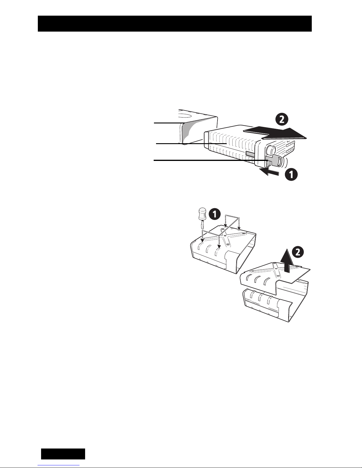
Installation de votre radio
impossible à l'utilisateur de toucher le dissipateur
thermique de la radio.
Démontage du
support
1 Pour retirer la radio de son support, insérez la clef
fournie avec la radio dans la fente située à gauche du
panneau avant, à côté de la commande de volume.
Support
Radio
Clef
Figure 2 : Support et clef
2 Pour démonter le
support, posez-le
sur une surface
ferme et apuyez, à
l’aide d’un
tournevis, sur l’une
des parties
saillantes du
milieu situées de
chaque côté du
couvercle, comme
l’illustre la Figure 3
Figure 3 : Démontage du support
ci-dessous. La partie métallique se détache alors de
la partie en plastique. Procédez de la même façon
pour démonter l’autre partie du couvercle.
Montage Tenez le couvercle en métal du support à l’endroit où
vous souhaitez installer votre radio et marquez la
position des 4 vis/écrous de fixation. Assurez-vous que
le forage à ces emplacements n’endommage pas les
câbles existants.
66
Français
Page 70
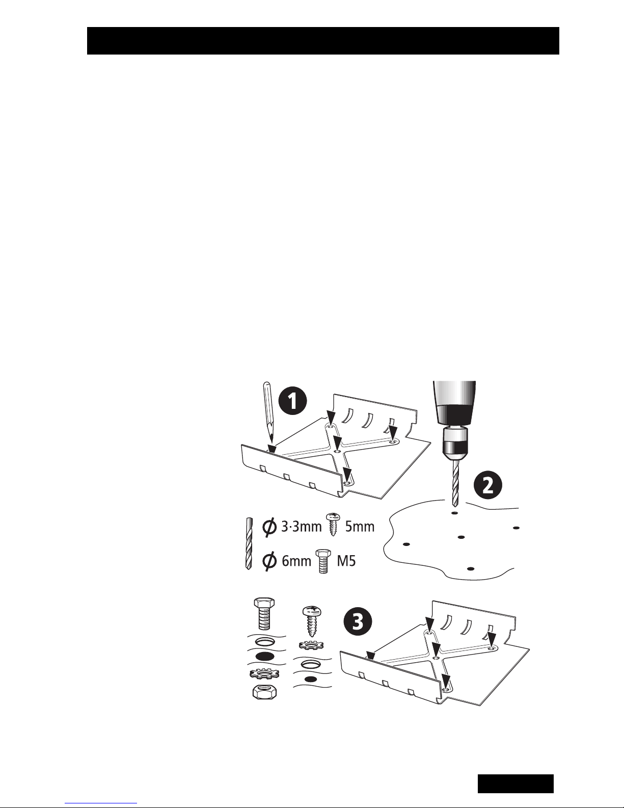
Installation de votre radio
Marquez les points de forage avec un pointeau à
centrer et forez des trous de 4 mm pour les vis autotaraudeuses ou de 6 mm pour les écrous. Réduisez la
taille du trou des vis auto-taraudeuses en cas
d’installation sur un métal d’une épaisseur inférieure à 1
mm.
Percez ensuite tous les trous nécessaires près du
support pour les câbles et remplissez-les avec des
rondelles de caoutchouc ou des traversées isolantes.
Fixez le couvercle métallique du support aux points
d’installation avec les vis auto-taraudeuses M5 fournies
ou avec des écrous et des boulons M5. Assurez-vous
que le serrage des vis ou des écrous ne déforme pas le
support..
Figure 4 : Montage
Français
67
Page 71

Assemblage du
support
Installation de votre radio
Figure 5 : Assemblage du support
Installation de
l’antenne
1Si l’antenne est dépendante de la masse, il est
recommandé de l’installer dans l’une des positions
suivantes :
*1---> 4 : Positions recommandées, par ordre décroissant
Figure 6 : Positions recommandée de l’antenne
2Si l’antenne est dépendante de la masse, il est
recommandé de l’installer dans l’une des positions
suivantes :
3 Installez l’antenne de façon à ce qu’aucune partie du
corps humain ne se trouve normalement à moins de
20 cm de celle-ci pendant plus de quelques minutes
lorsque la radio est allumée, à moins qu’un écran
métallique (par exemple un toit métallique) d’au
68
Français
Page 72

Installation de votre radio
a
a
a
a
aaaaaaaa
b
b
b
b
bbbbbbbb
moins 0,3 m2 (par exemple 0,55 m x 0,55 m) ne les
sépare.
4 Connectez l’une des extrémités du câble coaxial à
l’antenne. Des câbles coaxiaux de 50 ohms de
bonne qualité tels que RG58 ou UR76 sont
satifaisants. Placez l’autre extrémité du câble coaxial
à l’emplacement d’installation de la radio et coupez-le
de sorte qu’il y ait 200 à 300 mm d’excédent.
- Positionnez le manchon à sertir sur la gaine du
câble.
- Coupez la gaine extérieure du câble à une
longueur de 15 mm.
- Coupez la tresse à une longueur de 8,5 mm.
- Coupez l’isolant à une longueur de 11 mm. (Veillez
à ne pas endommager le conducteur central).
- Positionnez le contact mâle sur le conducteur
central en appuyant l’épaulement contre le bout de
l’isolant.
- Pincez le contact mâle sur le conducteur central.
- Appuyez l’ensemble fermement dans le trou à
l’arrière de la prise. Veillez à ce que la tresse ne
soit pas coincée entre l’isolant et l’intérieur de la
prise.
-Insérez le manchon à sertir sur la tresse et
appuyez-le contre l’épaulement de la prise.
- Pincez le manchon à sertir sur la tresse et la prise.
Manchon à sertir
aaaaaa
bbbbbb
aaaaaa
bbbbbb
Contact mâle
Figure 7 : Montage du connecteur d’antenne
Français
Prise
69
Page 73

Installation de votre radio
Câblage Haut-parleur externe
Certains modèles T2000
parleurs internes. Il est cependant possible d’installer un
haut-parleur externe. Un câble à deux conducteurs doit
être relié au connecteur d’alimentation. Pour désactiver
le haut-parleur interne, coupez la liaison avec le
connecteur d’alimentation, comme indiqué en Figure 6,
ci-dessous.
Les modèles T2000
nécessitent l’installation d’un haut-parleur externe. Dans
ce cas, le connecteur d’alimentation est équipé d’un
câble de haut-parleur.
Allumage
Externe
II sont équipés de haut-
II sans haut-parleur interne
Cavalier du
haut-parleur interne
(à couper pour désactiver)
Alimentation
secteur
Installez le haut-parleur externe à proximité de
l’utilisateur. Connectez l’extrémité libre du câble du haut-
parleur à la prise du haut-parleur.
Câble d’alimentation
1Déconnectez, si possible, la batterie du véhicule. Si
+13,8V
{
Masse
Figure 8 : Câblage du connecteur d’alimentation
cette procédure est interdite par le client, le fabricant
du véhicule, l’agent ou le fournisseur (à cause de
l’équipement électrique installé dans la voiture),
l’installation doit être effectuée avec beaucoup de
précaution. N’installez les fusibles qu’une fois
l’installation terminée.
Attention : Avant de connecter une seconde batterie
Masse
Phase
Haut-parleur externe
}
ou d’utiliser une alimentation provenant d’un autre
70
Français
Page 74

Installation de votre radio
véhicule, déconnectez le cordon d’alimentation de la
radio.
2Déterminez l’emplacement des câbles de la batterie.
3 Coupez les câbles négatifs et positifs à l’endroit où
vous souhaitez placer les pinces de fusible. (Les
fusibles doivent être installés aussi près de la batterie
que possible.)
4Insérez les deux extrémités du câble négatif dans
l’une des pinces de fusible et pincez-les pour
enfoncer les contacts métalliques sur les câbles.
Connectez le câble à la cosse de masse de la
batterie.
5Procédez de la même façon pour le câble positif et
connectez-le à la borne positive (+) de la batterie.
Attention : Veillez bien à ce que les câbles
d’alimentation ne frottent pas contre des parties
métalliques.
Remarque : Les radios T2000II sont conçues pour
fonctionner sur 12 V nominal (alimentation négative
de la masse) et nécessitent un courant de 8 A
maximum. Les radios tolèrent une plage de tension
d’alimentation de 10,8 V à 16 V. Dans les véhicules
équipés d’un système électrique de 24 V (c’est le cas
dans de nombreux camions), il est essentiel
d’installer un convertisseur 24/12 V (par exemple Tait
T2007) afin d’isoler la radio de la batterie et de la
protéger contre des tensions excessives.
6 Si la mise en veille doit être contrôlée par la ligne de
contact de l’allumage, fixez un câble au connecteur
d’alimentation et connectez le câble d’allumage à une
alimentation de +12 V qui n’est sous tension que
lorsque le contact du véhicule est allumé.
Français
71
Page 75

Installation de votre radio
Câble extérieur
(avertisseur
sonore/
silencieux/
urgence)
Option
panneau avant
déporté
Le T2000
pour faire fonctionner le klaxon du véhicule, la radio ou
un commutateur dissimulé :
1 Connectez une longueur de câblage adéquate au
port “externe” du connecteur d’alimentation.
2 Amenez ensuite l’autre extrémité du câble jusqu’au
câblage approprié du véhicule.
Pour connaître le fonctionnement exact de l’interface
d’options, consultez les instructions fournies avec cette
dernière.
La tête de commande de certains modèles T2000
peut être installée à distance du châssis de la radio.
Dans ce cas, la tête de commande doit être située à
l’abri de la lumière directe et le câble la reliant à la radio
II peut être configuré de la façon suivante
II
doit passer loin de l’antenne. Assurez-vous également
que le câble ne risque pas d’être endommagé.
Si le câble doit passer à travers une cloison, vous
pouvez débrancher le câble de la tête de commande
comme suit :
1Dévissez l’arrière du panneau avant et enlevez le
couvercle arrière en veillant à ne pas perdre les deux
écrous situés à chaque extrémité.
2 Retirez le connecteur rouge de la prise de la carte
imprimée afin de libérer le câble.
3 Passez le câble avec précaution à travers les trous
(installez des rondelles de caoutchouc dans les trous
si le câble risque d’être abîmé).
4 Replacez le connecteur dans la prise de la carte
imprimée (la forme du connecteur est telle qu’il n’est
possible de l’installer que dans un sens).
5 Replacez le câble sur le collier de câble, sur le
couvercle arrière, et glissez les deux écrous dans les
72
Français
Page 76

Installation de votre radio
logements situés à chaque extrémité du couvercle
arrière.
6 Replacez le couvercle arrière. Installez ensuite les vis
sur le couvercle arrière et serrez-les avec précaution.
(Ne les serrez pas trop.)
Vous pouvez alors monter la tête de commande en
procédant comme suit :
7 Installez le support du panneau avant sur une surface
plane à l’aide des vis auto-taraudeuses livrées avec
la radio.
8 Placez la tête de commande dans le support,
Figure 9 : Option panneau avant déporté
positionnez-la de façon à ce qu’elle soit bien visible
par le conducteur et serrez les deux vis.
Français
73
Page 77

Installation de votre radio
Clip du
microphone
Vérifications
d’installation
Si la fixation du microphone doit commander la fonction
moniteur, le balayage et mettre fin aux appels, le clip du
microphone doit être relié à la masse (à la ligne
d’alimentation négative). Pour plus de détails
concernant les fonctions de la fixation du microphone,
reportez-vous aux instructions d’utilisation de la radio.
Assurez-vous que le clip du microphone est installé de
façon à éviter l’appui accidentel du bouton d’alternat.
1 Branchez le microphone dans la prise en bas à
gauche du panneau avant de la radio et poussez
ensuite la bague du câble dans l’ouverture
rectangulaire du panneau.
2Insérez les fusibles dans le câble d’alimentation.
3 Mettez la radio en marche et vérifiez qu’elle
fonctionne.
4 Connectez un appareil de mesure de puissance en
ligne entre la radio et l’antenne et mesurez les
niveaux de puissance directe et réfléchie. Il devrait y
avoir au moins 1 W en puissance réfléchie pour 25 W
en puissance directe. Si ce n’est pas le cas, vérifiez
l’installation (y compris la longueur de l’antenne).
5 Pour finir, lancez un appel vers un autre utilisateur
(suivant les instructions d’utilisation de la radio).
74
Français
Page 78

T2030
T2035
II
II
Guía del Usuario
Español
75
Page 79

Medidas de seguridad
• Procurar no aproximar ninguna parte del cuerpo a la
antena a una distancia de 20 cm por algunos minutos,
mientras la radio está transmitiendo, a menos que
exista una protección metálica de intermedio.
• PELIGRO: APAGAR LA RADIO EN LAS
ESTACIONES DE SERVICIO DE GASOLINA
• PELIGRO: APAGAR LA RADIO EN LAS
CERCANIAS DE APARATOS EXPLOSIVOS (tales
como canteras en donde se practiquen técnicas
explosivas).
• El uso de un micrófono manual o una radio, mientras
se conduce un vehículo, puede contravenir las leyes
que se aplican en diferentes paises o estados. Es
conveniente consultar la reglamentación del tránsito
correspondiente.
Cumplimiento con la EN60950
Esta radio cumple con la Norma de la Unión Europea
EN60950 cuando funciona con un ciclo de servicio
nominal de hasta 33%, consistente en dos minutos de
transmisión y cuatro minutos de recepción, y a
temperaturas ambiente de 30°C o inferiores. El
funcionamiento por fuera de estos límites puede
provocar que la temperatura externa de la radio se
eleve más allá de lo que esta norma especifica.
Para garantizar el cumplimiento de la EN60950, la radio
debería estar montada en una posición que impida que
el usuario entre en contacto con los alerones de
disipación de calor de la radio.
76
Español
Page 80

Información de conformidad
Medidas de
protección
sanitaria, medidas
de seguridad y
compatibilidad
electromagnética
en Europa
En la Comunidad Europea, el equipo de radio y
telecomunicación está regulado por la Directiva
1999/5/CE, también conocida como la directiva del
Equipo Terminal de Radio y Telecomunicaciones
(R&TTE). Los requisitos de esta directiva incluyen
las medidas de protección sanitaria y medidas de
seguridad de los usuarios, así como exigen la
compatibilidad electromagnética.
Propósito intencionado del producto
Este producto es un transceptor de radio FM, cuyo
propósito es ser utilizado para la radiocomunicación
en los servicios de radio móvil privada (PMR) o en
los de radio móvil de acceso público (PAMR).
Importante: Este producto podría programarse con
frecuencias o emisiones de uso ilegal. Antes de
poder utilizar el equipo es imprescindible obtener
una licencia. Deben cumplirse todos los requisitos
pertinentes a la misma. Puede que haya
restricciones aplicables a la potencia de
transmisión, la frecuencia de funcionamiento, el
espaciamiento entre canales y la emisión.
Declaración de conformidad
En la página 2 se enumeran brevemente las
declaraciones de conformidad. La declaración
oficial puede descargarse de http://
eudocs.taitworld.com/.
Una copia en papel firmada de dicha declaración
puede obtenerse de Tait Europe Ltd.
Español
77
Page 81

Información de conformidad
Compatibilidad
electromagnética
en los vehículos
europeos
Límites de las
emisiones de
frecuencia de radio
en los Estados
Unidos
En la Comunidad Europea, el equipo de radio
integrado en los automóviles está regulado por la
Directiva 72/245/CEE, modificada por 95/54/CE.
Los requisitos de esta directiva son pertinentes a la
compatibilidad electromagnética del equipo
eléctrico o electrónico incorporado en los
automóviles.
Importante: Para cumplir los requisitos de la
Directiva 72/245/CEE (modificada por 95/54/CE), la
instalación de este producto en un vehículo debe
realizarse siguiendo las instrucciones y pautas
suministradas por el fabricante del vehículo.
La Sección 15 de la Normativa FCC impone límites
a las emisiones de FR de los equipos electrónicos
para evitar interferencias en la recepción de los
servicios de difusión. La operación de este
producto está sujeta a la condición de que el
Información
adicional
dispositivo no cause interferencias nocivas.
Importante: Si se realizan cambios o
modificaciones que no hayan sido expresamente
autorizados por Tait Electronics Ltd, el uso del
producto puede ser ilegal.
Para información sobre el producto y detalles de las
personas a contactar en Tait, visite:
http://www.taitworld.com/.
Para asistencia técnica, visite
http://support.taitworld.com/.
78
Español
Page 82

Para comenzar
Introducción Las radios T2030/35
ser usadas para hacer las siguientes tipos de llamadas:
• Llamadas de voz a otras radios, conectadas a una
flota y a otras diferentes
• Llamadas de voz en una Red Telefónica
• Mensaje de llamadas de estado para un destino
previamente programado, como por ejemplo a un
despachador.
Variación en
el ajuste de
la radio
Las radios T2030/35
microprocesador que está diseñado para satisfacer
todas las necesidades de una flota. Por esta razón,
algunas características descritas en esta guía pueden
operar diferentemente en la radio.
Si no sucede de esta manera, consultar a su
II de sistema troncalizado pueden
II están controladas por un
Cómo
encender
la radio
Uso del
micrófono y
el botón PTT
distribuidor Tait.
Para encender la radio girar el control de Encendido/
Apagado y Volumen aproximadamente un tercio de su
máxima capacidad. Se deberá ajustar el volumen para
hablar cuando se reciba la primera llamada.
El indicador de servicio (SVC) normalmente se ilumina
durante algunos segundos. Si esto no sucede puede
que se esté fuera del área de cobertura de la red.
Durante una llamada, usar el botón PTT para cambiar
la radio entre las funciones de transmisión y recepción.
Presionar el botón PTT para hablar, soltarlo para
escuchar. El indicador TX se ilumina durante la
transmisión.
Español
79
Page 83

Cómo hacer una llamada
Esta sección describe cómo seleccionar el destino de
una llamada y cómo conectarla. Dependiendo del tipo
de radio que se tenga y el tipo de llamada que desee
realizar, consultar la sección apropiada que se indica a
continuación.
T2030
T2035
II
II
Todas las llamadas disponibles en la radio T2030II
están previamente instaladas por la persona que
programa la radio. Dependiendo de cómo esté
programada la radio se podrá hacer llamadas a
diferentes destinos, incluyendo otras radios que se
encuentran en la red y números de teléfono.
Para hacer una llamada presionar una de las teclas de
Llamada ( a ) o la tecla Despachador
( ). Todas éstas teclas pueden ser instaladas
previamente para llamar a distintos lugares. La tecla
Despachador ( ) es la que usualmente se usa
para colocar una llamada a la base estación o
despachador.
La persona que programa la radio designará una tecla
para cada uno de los destinos.
La persona que programa la radio designará una tecla
C1
C4
para cada uno de los destinos.
Cómo hacer una llamada en la radio T2035
1 Utilizar el teclado numérico para ingresar el número
que se desea llamar.
2 Presionar la tecla de Llamada ( ) para iniciar la
llamada.
La persona que programa la radio advertirá de la
llamada previamente fijada y números de identificación
personal que se deberá usar para llamar a diferentes
destinos.
Dependiendo de la programación es como se podrá
hacer hasta tres diferentes tipos de llamadas:
• Llamadas previamente programadas a cualquier
destino
• Llamadas directas a identificadores de otros en la red
• Llamadas de grupo a dos o más identificadores.
II :
80
Español
Page 84

Cómo recibir una llamada
Cuando se
recibe una
llamada
Los tonos usados para avisar que se tiene una llamada
pueden variar, dependiendo de cómo esté programada
la radio o del tipo de red que se esté usando.
Ambos tonos de alerta están ilustrados a continuación
junto a las instrucciones para contestar los diferentes
tipos de llamadas entrantes.
Tono Para contestar
Esta es una llamada directa. Cuando el
Dos tonos
o un solo tono
indicador GO (hablar) se ilumine levantar
el micrófono y responder.
1 Levantar el micrófono del gancho.
Un tono de timbre
2 Esperar mientras la radio conecte la
llamada.
3 Contestar cuando el indicador WAIT se
apague y el indicador GO se encienda
Cómo
identificar al
interlocutor
T2030
T2035
II
II
o presionar la tecla de Borrado ()
para rechazar la llamada.
Si las llamadas entrantes corresponden a aquellas que
están programadas en la radio, entonces la radio
mostrará el identificador de la siguiente manera:
El indicador pre-instalado correspondiente a la tecla
apropiada se encenderá.
El número pre-instalado de la persona que está
llamando aparecerá en la pantalla.
Más información puede ser mostrada en la radio
T2035
Si la llamada viene:
Desde su flota
II como sigue:
El T2030/35
II
muestra:
El identificador de la flota
de su interlocutor
Desde fuera de su flota
Desde un teléfono
Sin identidad
.1.
.2. or .3.
.4.
Español
81
Page 85

Cómo contestar las llamadas
Usar las funciones de la memoria descritas a
continuación para restablecer las primeras llamadas y
devolver las que no han sido contestadas.
Llamada
de vuelta
Cuando una llamada entrante termina, la radio
almacenará el número del interlocutor.
El indicador de la tecla Llamadas de vuelta se
encenderá de forma intermitente en el T2030
número o identificación, antes fijado, de la persona que
está llamando, se mostrará de forma intermiten-te
también, en la pantalla del T2035
Para devolver la llamada, presionar la tecla Llamadas
de vuelta ( ) (T2030
( ) (T2035
(hablar) se encienda y proceder de manera usual.
Se puede también estar responder una llamada
presionando suavemente el botón PTT (dependien-do
de cómo esté programada la radio).
II). Esperar que el indicador GO
II), o la tecla de Llamada
II.
II, y el
Marcación
automática
Llamadas
en espera
II
(T2035
solamente)
El último número que se ha llamado se encuentra
también almacenado en la memoria de la radio. Para
llamar nuevamente, presionar el botón PTT.
Si la radio está en la función de «Llamadas de vuelta»,
presionar la tecla de Borrado ( ) para descartar la
identificación de la llamada, antes de marcar
nuevamente.
La radio T2035
para ubicar en espera hasta 20 números de
identificación de llamadas sin contestar.
Para tener acceso a las llamadas en espera, presionar
la tecla En espera ( ) y mantener presionada la
tecla Despachador ( ) aproximadamente un
segundo. El indicador de la tecla En espera se
II puede ser previamente programa-da
encenderá. Presionar la tecla Despachador ()
nuevamente para abandonar la espera.
82
Español
Page 86

Cómo contestar las llamadas (continuación)
Estando en la función de espera, presionar la tecla
correspondiente para desplazarse a través de la lista de
Identificadores. Cuando se llegue al final de la lista la
radio emitirá un sonido y cambiará el desplazamiento
en el sentido contrario.
Para devolver cualquier llamada que se encuentre en la
lista de identificadores, presionar el botón PTT o la tecla
de Llamada ( ) cuando el identificador se muestre
en pantalla. Para borrar un identificador de la lista,
presionar la tecla de Borrado ().
Operación de
emergencia
Información adicional
Para utilizar la Operación de Emergencia, la radio
deberá estar conectada a un interruptor de emergencia
oculto, que debe ser programado para hacer llamadas
de emergencia.
Para hacer una llamada de emergencia seguir los
siguientes pasos:
• Poner en funcionamiento el interruptor oculto.
• La radio entonces enviará un mensaje para alertar a
la parte interesada que se está en dificultades.
• Mientras una llamada de emergencia está en curso, la
radio se apagará y encenderá silenciosamente en el
modo de transmisión, para poder controlar las
actividades alrededor de la radio.
• Se puede reajustar la radio con sólo apagarla y
Operación
despachador
Las radios T2030/35
despachador de operación, instaladas sobre la parte
superior de un suministro de energía T2008 que se
puede adquirir en forma separada. La radio debe ser
programada para funcionar como despachador.
encenderla.
II se pueden usar como un
Español
83
Page 87

Información adicional (continuación)
Función
de bajo
consumo
Duración
máxima de
la llamada
Mantención Las radios T2030/35
Para conservar energía la radio puede ser programada
para disminuir la luminosidad de la pantalla o
simplemente apagarla y también para apagar la
iluminación del teclado frontal después
de un determinado período de inactividad.
Presionar el botón PTT o cualquier tecla del panel para
activar la radio a su condición normal. (La actividad
válida en el canal seleccionado tendrá el mismo efecto.)
La radio está programada con un marcador de tiempo
para medir el largo de las transmisiones.
La radio le dará una señal antes de dejar de transmitir.
forma regular, aparte de asegurarse de que todos los
II no requieren mantención en
Resolución
de
probemas
Códigos de
información al
hacer una
llamada:
cables se encuentren firmes y bien conectados, y que la
antena o los cables no sufran ningún daño.
Si ninguno de los indicadores del panel frontal se
enciende cuando se encienda la radio, es posible que
no esté llegando energía. Revisar todos los cables, los
fusibles en línea y las conexiones que van desde la
batería a la radio.
Si el problema persiste, consultar con un distribuidor
Ta it .
Códigos
“0. .1” parpadeando El sistema está ocupado
“0. . 2” parpadeando Llamada no disponible
“0. . 3” parpadeando No se puede obtener
T2030/35
II
“0. . 4” parpadeando La parte llamada está ocu-
84
Español
número
pada
Page 88

Cómo sacar la radio del vehículo
Cómo sacar
la radio de
su soporte
Por razones de seguridad se puede quitar la radio
de su soporte usando la llave especial, de la
siguiente manera:
1 Apagar la radio.
2 Introducir la llave en la
ranura que se
encuentra al lado del
control de volumen,
como se muestra en
la ilustración.
3 Sostener el panel frontal de la radio por sus costados
y tirar hasta que la radio quede libre de su soporte.
4 Desconectar la antena y demás cables desde la
parte posterior de la radio.
5 Sacar la radio.
Español
85
Page 89

Instalación de la Radio
Componentes
del Equipo de
la Serie T2000
Accesorios incluídos en los equipos de la serie T2000
• Radio T2000
II
• Micrófono
• Armadura de soporte
• Parlante de 4 ohmios (no aptos para modelos con
parlante interno)
Equipo de instalación:
• Conector de dos vías (1)
• Enchufe de receptáculo (2)
• Fusible 12 V a 10 A (2)
• Interconector de cables en
líneas (2)
• Tornillos autorosca (4)
II
• Conector BNC para la antena
• Llaves del soporte (2)
• Cable de alimentación (5m)
• Arandela a prueba de
vibración (4)
• Gancho para
el micrófono (1)
• Soporte para sujetar el
panel de control (T2020
y T2040
II solamente)
II
II
Figura 1: Componentes del Equipo de la Serie T2000
Herramientas
Recomendadas
para la
Instalación
86
Español
• Taladro portátil
• Punzón metálico
• Brocas: 4mm para tornillos autorosca, 6mm para
tuercas y pernos
• Destornillador “Pozidriv”
• Pinza para terminales BNC (e.g. Transradio England
Duo crimp 894)
• Medidor de potencia transmitida y reflejada a la
frecuencia de operaciones de la radio.
• Martillo
II
Page 90

Instalación de la Radio
Planificació
n de la
Instalación
Seguridad
de los Ocupantes
Para asegurarse de llevar a cabo una instalación eficiente y sin
problemas, inspeccione el vehículo y determine cómo y dónde
van a ser instalados la antena, la radio y demás accesorios.
Los modelos T2020
anumérico y el panel de control aparte del chasis de la radio,
pueden ser montados separadamente uno del otro. Esto permite que la radio sea montada en un lugar discreto, por ejemplo en la cajuela posterior, con el panel de control montado en
una posición conveniente para los ocupantes del vehículo.
Para más detalles consultar el manual de servicio M2000, que
puede ser adquirido de su distribuidor Tait.
Inspeccione que los sitios escogidos para la radio y sus accesorios no pongan en peligro a los ocupantes del vehículo. No
se recomienda instalaciones por encima de la cabeza especialmente sin abrazaderas de soporte adicionales. Asegúrese
II and T2040II que tienen el teclado alf-
que la radio puede ser operada convenientemente una vez
que los ocupantes se hayan colocado los cinturones de seguridad.
Precaución: Para prevenir interferencias con los sistemas
electrónicos del vehículo (tales como dispositivos del encen-
dido, anti-deslizamiento, etc), la radio, su antena y el tendido
eléctrico deben ser montados lejos de esas unidades y sus
cables.
Asegúrese de que hay suficiente corriente de aire alrededor de
la radio para obtener un enfriamiento adecuado. Una vez que
haya encontrado una posición adecuada para la radio, sostén-
gala (encajada dentro de la armadura de soporte) en la posición escogida para su montaje y compruebe que quede
suficiente espacio en la parte trasera para el disipador de calor,
los cables, etc. Compruebe que la posición facilite una superfi-
cie suficientemente plana como para que la armadura de
soporte no se deforme.
Para garantizar el cumplimiento de la EN60950, la radio
debería estar montada en una posición que impida que el
Español
87
Page 91

Instalación de la Radio
usuario entre en contacto con los alerones de disipación
de calor de la radio.
Desmontaje de
la Armadura de
Soporte de la
Radio
1 Para desmontar la cubierta de la radio, inserte la llave
plástica en la ranura junto al control de encendido,
luego deslice la cubierta sujetando la parte frontal de
la radio, como se muestra en la figura 2.
Soporte
Radio
Llave plástica
Figura 2: Desmontaje de la Armadura de Soporte del T2000II
2 Coloque el
soporte sobre una
superficie firme y
presione una de
los bordes
centrales de
plástico, con un
destornillador
como se muestra
en la figura 3. De
esta manera se
desprenderá el
Figura 3: Desmontaje de la
Armadura de Soporte del T2000
II
plástico del mismo
costado. Hago lo mismo del otro lado.
Montaje Utilice la parte inferior del soporte como plantilla para
marcar las perforaciones, donde se sujetará el soporte.
Al perforar tenga cuidado de no dañar algún cable.
Utilice el punzón metálico para iniciar el camino de la
broca del taladro. Los agujeros deben ser de 4mm para
88
Español
Page 92

Instalación de la Radio
tornillos “autoroscas” o de 6mm para pernos con
tuercas. Reduzca el tamaño de los agujeros si se trata
de colocar tornillos auto roscas en una superficie
metálica inferior a 1mm de espesor.
Perfore otros agujeros que se requieran para cables
cerca de armadura de soporte y coloque en ellos
casquillos y arandelas aislantes.
Fije la armadura metálica a los puntos de sujeción con
los tornillos autoroscas M5 suministrados o con los
pernos y tuercas M5. Asegúrese que al apretar los
tornillos o pernos, no se deforme la armadura.
Figura 4 - Montaje
Español
89
Page 93

Para
Reensamblar la
Armadura de
Soporte
Instalación de la Radio
Figura 5: Reensamble de la Armadura de Soporte
Instalación de
la Antena
1 Si la antena depende de un plano de tierra para su
operación, se recomienda su instalación en
cualquiera de las posiciones indicadas a
continuación:
*1=más adecuada *4=menos adecuada
Figura 6: Posiciones Recomendadas para la Antena
2 Ti la antena es del tipo “independiente de la tierra”
deberá ser instalada en el vehículo según las
intrucciones que acompañen a la antena.
3 Colocar la antena en una posición tal que ninguna
parte del cuerpo humano esté normalmente dentro
de 20cm de su perímetro, por algunos minutos,
mientras la radio esté encendida, a no ser que exista
una protección metálica mediadora (ejem. un techo
90
Español
Page 94

Instalación de la Radio
a
a
a
a
aaaaaaaa
b
b
b
b
bbbbbbbb
metálico) de por lo menos 0.3m2 de área (ejem.
0.55m x 0.55m).
4 Conectar un extremo del cable coaxial en la antena.
Cables de 50 ohmios de buena calidad como el
RG58 ó el UR76 son apropiados. Cablear el extremo
libre del cable coaxial hacia el lugar de montaje de la
radio y cortarlo a un largo entre 200mm a 300mm.
5 Colocar en el extremo libre del cable el conector
BNC, como se muestra en la figura 7.
- Introduzca el casquillo en el cable coaxial.
- Recorte el plástico externo del cable coaxial a 15
mm (tal como se muestra en la figura 7).
- Recorte el cable trenzado a 8.5 mm (dialéctrico).
- Recorte el aislante interno a 11 mm. (tenga mucho
cuidado de no cortar el conductor central con la
herramienta).
- Introduzca el cable central en el pin hasta unirse
con el dieléctrico.
- Apriete el pin con la herramienta adecuada, para
que este quede bien sujeto al cable central.
- Introduzca el conector BNC en el pin y presione
hasta que quede bien ensamblado. (Asegurese
que el cable trenzado no haga contacto con el
cable conductor).
- Desplace el casquillo metálico y presione hasta el
tope del conector BNC.
- Utilice la herramienta adecuada para presionar el
casquillo metálico contra el cable trenzado.
Casquillo de apriete
Figura 7: Ensamble del Conector de la Antena
aaaaaa
bbbbbb
aaaaaa
bbbbbb
Pin
Conector
Español
91
Page 95

Instalación de la Radio
Conecciones Parlante Exterior
Algunos modelos T2000
internos. Es posible sin embargo, instalar un parlante
externo si se desea. Un cable doble debe conectarse al
enchufe de alimentación. Para anular el parlante
interno, corte el puente en el enchufe de alimentación
como se indica a continuación.
Los modelos T2000
que se les incorpore un parlante externo. El enchufe de
alimentación tiene instalado el cable para el parlante.
Suministro
de voltage
Encendido
Externo
+13.8V
{
Tierra
II vienen con parlantes
II sin parlante interno necesitan
Parlante Externo
Interno (cortar
para desactivar)
Tierra
Señal
Conexion del
}
Parlante
Figure 8: Esquema de Conexiones del Enchufe de Alimentación
Instale el parlante externo en un lugar conveniente
cerca del operador. Dirija el extremo libre del cable del
parlante y conectelo a las terminales de éste.
Cable de Alimentacion de Energia
1 Desconecte la batería del vehículo o menos que esté
específicamente prohibido hacerlo por el cliente, el
fabricante del vehículo, el agente o distribuidor,
debido al tipo de equipo eléctrico ya instalado en el
vehículo. En este caso, se debe tener extremo
cuidado durante la instalación colocando siempre los
fusibles al final, una vez que se haya completado la
instalación.
Precaución: Desconecte siempre los cables de
alimentación de la radio antes de conectar una
segunda batería o si está usando energía desde otro
92
Español
Page 96

Instalación de la Radio
vehículo, (por ejemplo recibiendo corriente desde
otro vehículo).
2 Determine por donde deberán instalarse los cables a
la batería.
3 Corte los cables positivo y negativo de tal manera
que el respectivo interconector de cables en línea
quede lo más cerca posible de la batería.
4 Inserte cada extremo del cable negativo dentro de
uno de los interconectores de cables en línea
presionando y forzando los contactos. Conecte el
otro extremo a la tierra de la batería.
5 Repita el paso anterior con el cable positivo y
concluya conectandolo al terminal positivo de la
batería.
Precaución: Tenga especial cuidado en prevenir que
los cables de alimentación no se raspen en ninguna
parte metálica.
Nota: Las radios T2000II están diseñadas para
trabajar con una fuente de 12V nominales, tierra
negativa y requieren de una corriente de hasta 8A.
(Estas radios pueden soportar una variación de
voltaje entre 10.8V y 16.0V). En vehículos con
sistemas eléctricos de 24V (como por ejemplo
muchos tractores), es esencial proveer un
convertidor apropiado de 24/12V. (como por ejemplo
Tait, T2007) para aislar la radio de la batería y
protegerla de voltages excesivos.
6 Si es que el economizador va a ser controlado desde
la toma del encendido, conecte un cable en el
enchufe de alimentación y el del encendido a una
fuente de +12V que esté activa solo cuando el
conmutador del arranque esté en la posición de
“encendido” (on).
Español
93
Page 97

Instalación de la Radio
Cable Externo
(Bocina/
Silenciador/
Emergencia)
Opción de
Panel de
Controles
Separado
Las radios T2000
operar la bocina del vehículo, la radio o un interruptor
oculto.
1 Corte un cable con un largo apropiado al pin
“externo” del enchufe de alimentacion.
2 Dirija el extremo libre del cable exterior del conector
de poder al tendido eléctrico apropiado del vehículo.
La opción de interfase es usualmente configurada para
activarse o ser activada con una conección a tierra. La
operación exacta debe ser confirmada consultando las
intrucciones de la unidad de interfase.
El panel frontal de control de algunos modelos T2000
puede que esten listos para ser montados
separadamente del chasís de la radio. En este caso
debe ser localizado lejos del contacto directo de la luz
II puede ser configuradas para
II
solar y el cable que lo conecta a la radio debería ser
colocado a distancia de la antena asegurándose que
no estará expuesto a daño alguno.
Si es necesario pasar el cable a través de algún
tabique, o alguna obstrucción similar, desconecte el
cable del panel frontal de control como sigue:
1 Desatornille la parte posterior del panel de control y
levante la cubierta posterior, teniendo cuidado de no
perder las dos tuercas localizadas en cada extremo.
2 Desconecte el conector rojo desde el enchufe de la
tarjeta de circuito impreso para liberar el cable.
3 Dirija los cables como sea conveniente, colocando
arandelas de metal donde sea necesario, para
prevenir raspaduras en el cable de aislamiento.
4 Instale el conector rojo al enchufe de la tarjeta de
circuito impreso. El conector está perfilado de
manera que puede ser colocado en la posición
correcta solamente.
94
Español
Page 98

Instalación de la Radio
5 Reinstale el cable en la abrazadera que se encuentra
en la cubierta posterior y coloque las dos tuercas en
sus receptáculos a cada extremo de la cubierta
posterior.
6 Coloque nuevamente la cubierta posterior con sus
tornillos. No apriete demasiado.
El panel de control puede ser ahora instalado de la
siguiente manera:
7 Monte la abrazadera para el panel frontal de control
sobre una superficie plana, usando los tornillos
autorosca suministrados.
Figura 9: Opción de Panel de Controles Separado
Español
95
Page 99

Instalación de la Radio
8 Coloque el panel de control en la abrazadera y
presentelo de tal manera que exista un buen ángulo
visual, luego ponga los dos tornillos para asegurarlo.
Gancho para el
Micrófono
Verificación de
la Instalación
Si se desea habilitar el control del monitoreo, el registro
o el término de la llamada por intermedio del
conmutador de gancho, éste debe ir conectado a tierra
(a la línea negativa del suministro). Consulte las
instrucciones de operación de la radio para confirmar
los requerimientos del caso.
Asegúrese de que el gancho del micrófono está
colocado en una posición tal que el botón para hablar
(PTT) no se quede atascado o inadvertidamente
activado.
1 Conecte el micrófono en su conector en la esquina
inferior izquierda del panel frontal de la radio. Luego
empuje la arandela del cable dentro de la apertura
rectangular del panel.
2 Inserte los fusibles dentro de los cables de
Alimentación de Potencia.
3 Encienda la radio y confirme su funcionamiento.
4 Conecte en serie un vatímetro entre la radio y la
antena y mida los niveles de potencia en ambas
direcciones. Menos de un vatio debe ser reflejado por
25W de transmisión directa. Si esto no se consigue,
revise la instalación, incluyendo la longitud de la
antena.
5 Para finalizar, llame por la radio a otra persona como
se describe en las instrucciones de operación.
96
Español
Page 100

T2030
II
T2035
II
97
 Loading...