

Page 1

T2000-A76 AVL Modem
Operation Manual
© Tait Electronics Limited
Corporate HQ: PO Box 1645, Christchurch,
New Zealand.
Tel: +64 3 358 3399
Fax: +64 3 358 0340
Web: www.taitworld.com/
March 2003
M2303-00-P00-805
Page 2

Page 3

Contents
Section Title Page
1 Overview 5
1 Operation 6
2 Compatibility 8
3 GPS Interfaces 9
4 Programming the A76 12
5 Operation Sequences 14
6 Commands to the Remote Radio 17
7 Responses from the Remote Radio 21
8 CCDI Reference 24
Page 4

Page 5
March 2003 M2303-00-P00-805 5
1 Overview
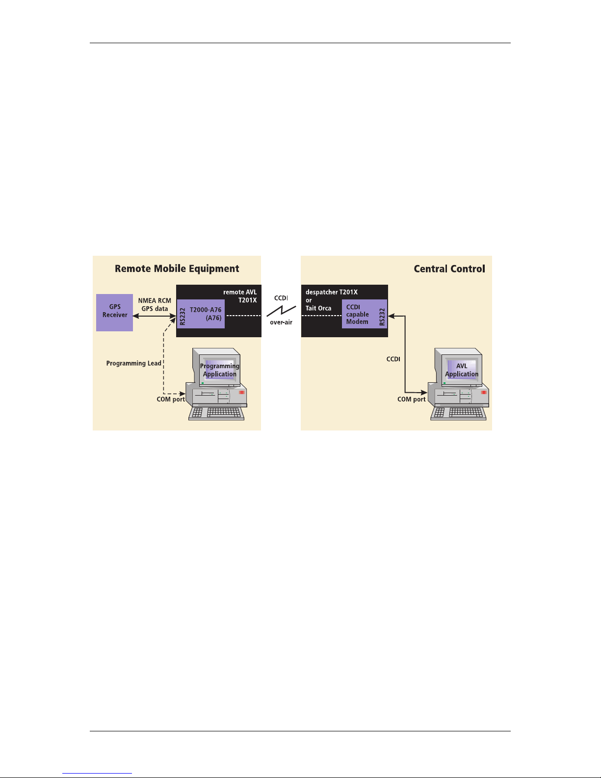
The T2000-A76 AVL Modem is fitted as an options PCB within a T201X mobile radio. The AVL enabled T201X
radio collects and stores AVL data from a GPS receiver in its internal memory, which can then be relayed to
central control equipment.
A typical AVL system comprises:
• a remote GPS receiver
• a remote AVL T201X radio with a T2000-A76 fitted internally
• a despatcher radio at the central control (CCDI capable T201X, Tait Orca or TRM )
• a central control personal computer (PC) running an AVL application (e.g. SmartTrac)
The AVL application instructs the despatcher radio to poll the remote radio for AVL position and velocity data
which, when returned, is stored by the AVL application. The remote radio can also be set to emergency mode
where it periodically sends unsolicited AVL data to the despatcher radio.
The despatcher radios uses the Tait CCDI (Computer Controlled Data Interface) over-air command protocol to
communicate with the remote radio. CCDI commands containing short data massages (SDMs) are sent to the
remote radio by the PC AVL application. Each SDM contains a command which tells the remote radio to one
of the following:
• send an AVL report
• send database information
• set the Group Delay Time
• control the AUX line output
• reset the radio
The despatcher radio is CCDI capable and connects to the PC by a serial line using standard RS232 signals.
The GPS receiver sends data to the A76 using the NMEA-0183 data transfer protocol. The A76 interprets the
RMC sentance from the GPS receiver.
Programming of the A76 is done using a special programming application from a PC via the serial port. Only
the Group Delay Time which enables group polling of radios can be programmed remotely.
Glossary
AVL Automatic Vehicle Location NMEA National Marine Electronics Association
GPS Global Positioning System RMC Recommended Minimum (specific GPS/transit data)
SDM Short Data Message UTC Universal Time Code
Page 6

6 M2303-00-P00-805 March 2003
2 Operation
Features
The A76 modem in the T201X radio performs the following AVL functions:
• AVL data collection from the GPS receiver
• simple AVL polling by the despatcher radio
• group AVL polling by the despatcher radio
• emergency unsolicited AVL reports to the despatcher radio
• PTT generated AVL reports
• AVL data transfer to another radio using the CCDI over-air protocol
• A76 configuration database modifications using Tait proprietary NMEA style messages
• auxiliary output control using RS232 CTS line
• FFSK tone blanking when data received
• reads the version of A76 firmware over-air
• programs the Group Delay Time over-air so that group polling can be configured
• reads the programmed Group Delay Time setting over-air
• over-air reset of the remote radio with or without initiating database
AVL Data Collection
The A76 modem collects and stores NMEA RMC data at intervals set by the GPS receiver. When a AVL poll is
sent from the AVL application to the remote AVL radio or an emergency activation occurs, an AVL report with
the stored data is immediately sent to the despatcher radio and saved by the AVL application. Refer to the
section , NMEA-0183 RMC Sentence Format, for a description of the NMEA RCM format. All RMC fields are
initialised with ‘0’.
Radio Signalling
The signalling between the despatcher radio and the remote AVL radio uses the Tait CCDI V2.0 terminal and
over-air protocol. CCDI Short Data Messages (SDMs) are used to send commands to the remote AVL radio and
to pass information back to the central control computer.
Auxiliary Output
The auxiliary output from the A76 uses the RS232 CTS line on the serial port to switch external devices on or
off. It can be remotely controlled by the despatcher radio by sending a AUX ON or AUX OFF message. Refer to
the Auxiliary Output Control section. This feature can be enabled or disabled by the A76 configuration.
Emergency Mode
Emergency mode is activated by the RTS input on the A76 serial port. If asserted, the A76 enters Emergency
mode and sends unsolicited reports at preset intervals. Refer to the Emergency Mode Activation section.
The Emergency mode feature can be enabled or disabled by the A76 configuration.
Page 7

March 2003 M2303-00-P00-805 7
PTT Activated AVL Reporting
The A76 can be configured to send an unsolicited AVL report each time the PTT is pressed or released. Refer
to the PTT Activated AVL Reporting section.
FFSK Tone Blanking
Tone Blanking is used for applications in which voice and data share the same channel. When valid data is
received, the FFSK Tone Blanking mutes the radio. If the A76 detect either preamble or synchronisation bytes
in the received FFSK data, the speaker is muted using the squelch line. Refer to the Programming the A76
section for database configuration information.
Error Handling
‘old’ If the NMEA RMC data from the GPS receiver has the status flag set to ‘V’ (invalid),
the AVL report is marked as ‘old’.
‘not operational’ If no AVL data is received from the GPS receiver for 20 seconds, an AVL report
marked ‘not operational’ is sent. The will occur if the GPS receiver is disconnected.
‘format error’ If a data error occurs, an AVL report is marked ‘format error’ is sent. This may be
due to mismatched baud rates, an incorrect checksum or corrupt NMEA data.
Refer to section 8, Responses from the Remote Radio, for the response message format details.
A76 Configuration
Programming using NMEA
The serial RS232 serial port on the A76 modem is configured to expect NMEA type format. This means that
the programming of the A76 database must be done using NMEA sentences rather than sending a standard
CCDI Program command as is used with both the T2000-A75 Modem and the Tat Orca/Tait Radio Modem.
For this purpose four new Tait proprietry NMEA messages have been created:
• PTPGM - for programming the database configuration
• PTWDB - response from the A76 ro a PTPGM message
• PTRDB - for reading the database configuration
• PTDAT - response from the A76 ro a PTRDB message
Refer to the Programming the A76 section for details of the PTPGM settings.
Remote programming of Group Delay Time
The Group Delay Time is the only database configuration item that can be programmed remotely.
This is done using the Program Database command with a SEND_SDM CCDI message. Refer tothe Commands
to the Remote Radio section for further details.
The Group Delay Time determines the time that a radio waits before responding to a AVL report Poll. This is so
that when a Group Poll is sent, all the radios in the group respond at different intervals rather then
simultaneously.
Page 8

8 M2303-00-P00-805 March 2003
3 Compatibility
T201X Radio Firmware
When programming the T201X radio firmware for use with the CCDI, use version 3.01 or greater.
Retrofitting an A76 AVL modem into a T201X radio, radios require radio firmware version 2.22 or later. If your
radio uses an earlier firmware version, a new microprocessor can be purchased as a separate item. Contact
your nearest authorised Tait dealer.
Remote Radio PGM Settings
When the A76 AVL modem board is fitted, the T201X PGM program settings have the following constraints:
• ‘BCD Channel Selection’ should be enabled and polarity set to Normal so that the A76 can change the
radio channel.
• Economy mode reduces the radio’s power consumption when it is idle. When economy mode is active
and there has been no valid activity on a channel for the duration of the economy mode timer, the
radio begins economy cycling. This means that the beginning of a transmission may be lost if it is
received after a period of inactivity.
If ‘Economy mode’ is enabled in a T201X with a CCDI modem fitted, set the default Lead In Delay in
the A76 configuration to 200 ms or greater.
The Lead In Delay can be reprogrammed as low as 40 ms, but the Economy mode must be disabled.
Despatcher Radio PGM Settings
The despatcher radio may be a Tait Orca, a Tait Radio Modem or a T2000 with a A75 fitted. Regardless of
which radio is used, the modem must have Auto Acknowledge set to disabled.
GPS Receiver
The GPS receivers supported must use the National Marine Electronics Association (NMEA) 0183 version 2.01
(or compatible) RMC serial communication standard with suitable transmission rate and data format.
Tait Supports two different types of receivers.
The T2002-A00 GPS Receiver
The T2002-A00 GPS Receiver is a weatherproof receiver suitable for mounting outside a vehicle. It requires
13.8V which needs to be supplied on pin 6 of the RS232 socket at the rear of the T201x. This is generally
supplied from S14 pin 1 of the T2000 Logic PCB.
The T2002-A00 has an optional mounting bracket (T2002-A01).
The T2003-A00 GPS Receiver
The T2003-A00 GPS Receiver is suitable for internal mounting. It requires 5V which needs to be supplied on
pin 4 of the RS232 socket at the rear of the T201x. This is generally supplied from S14 pin 2 of the T2000
Logic PCB.
Page 9
March 2003 M2303-00-P00-805 9
4 GPS Interfaces
RS232 Interface
The RS232 interface on the despatcher radio has the following parameters which are fixed in the radio
modem firmware.
For every byte sent, there are 10 bits sent including the start and stop bits:
• Number of data bits = 8
• Parity = none
• Number of start bits = 1 (set to ‘1’)
• Number of stop bit = 1 (set to ‘0’)
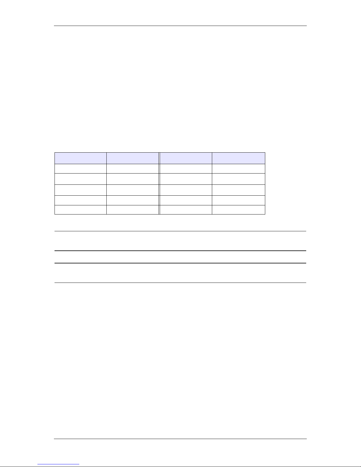
The RS232 D-Range socket at the rear of the T201X radio has the following configuration:
* not available in the standard T201X without a T2000-A76 PCB fitted.
Caution: Note that RS232 pin labelling can be misleading. A straight-trough cable is used to connect the
GPS receiver to the T201x radio..
Note: The start and stop bits are removed by the modem for the over-air transmission of data. The FFSK data
sent is pure binary 8 bit data only.
Connections Function Connections Function
1 Not used 6 T2002-A00 supply
2TXD7
RTS
*
3RXD8
CTS
*
4 T2003-A00 supply 9 Not used
5 GND
Page 10
10 M2303-00-P00-805 March 2003
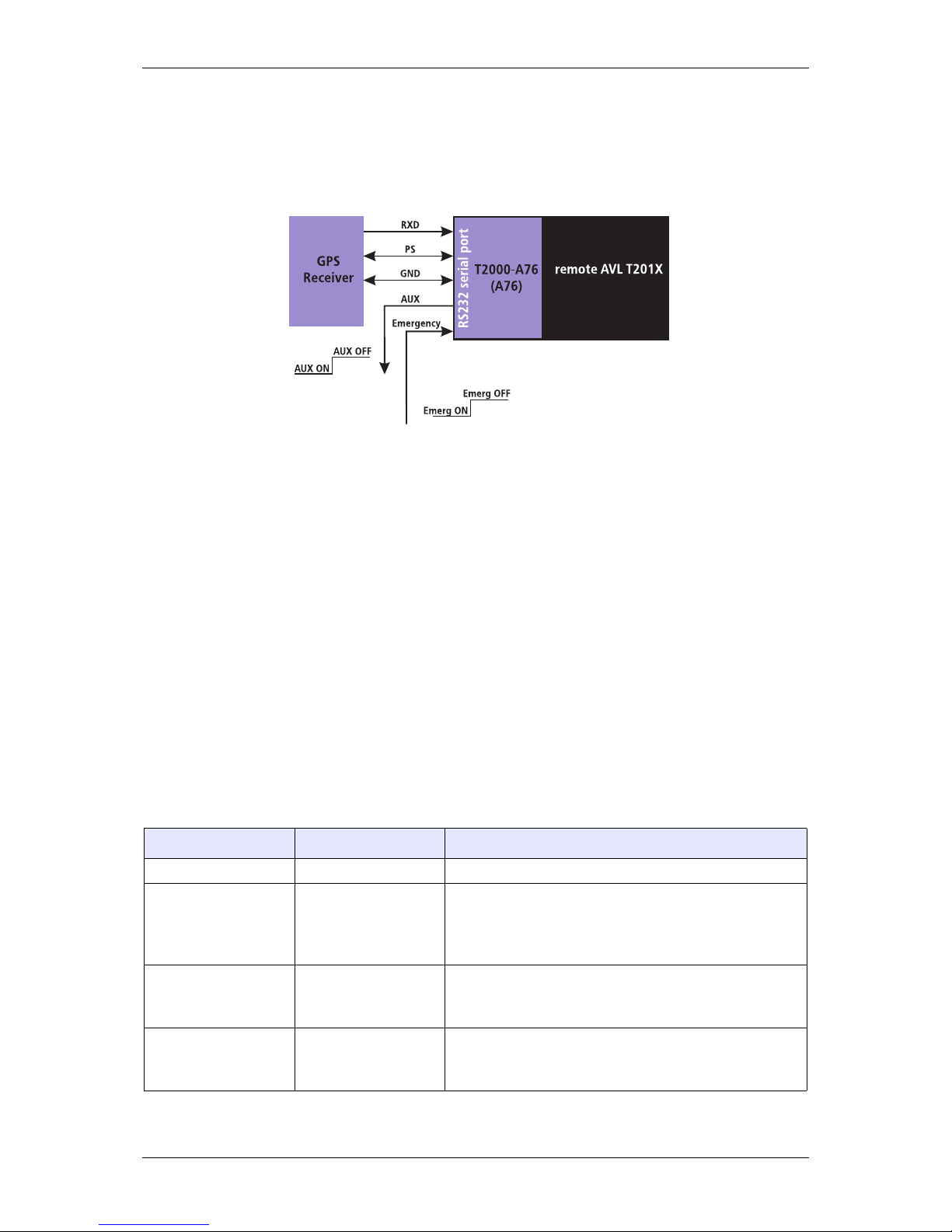
RS232 from Remote Radio to GPS Receiver
The NMEA data transfer between the Remote AVL radio and the GPS receiver uses only the RXD data line. CTS
and RTS are used to active/deactivate the Aux Control line and Emergency mode respectively.
NMEA-0183 RMC Sentence Format
The NMEA RMC sentence is sent by the GPS receiver to the A76 in the remote AVL radio.
NMEA-0183 is a serial communication standard for encoding and sending GPS and other navigational data
between devices. All characters are ASCII (plus carriage return and line feed).
The data is transmitted as sentences, beginning with a $, a two letter sender ID, a three letter sentence ID,
followed by data fields separated by commas. The sentence is terminated with a checksum and a carriage
return and line feed. A sentence can contain up to 82 characters.
If a data field is empty, a comma is still inserted.
This application of the NMEA standard uses the RMC sentence format which is especially formulated for AVL
data.
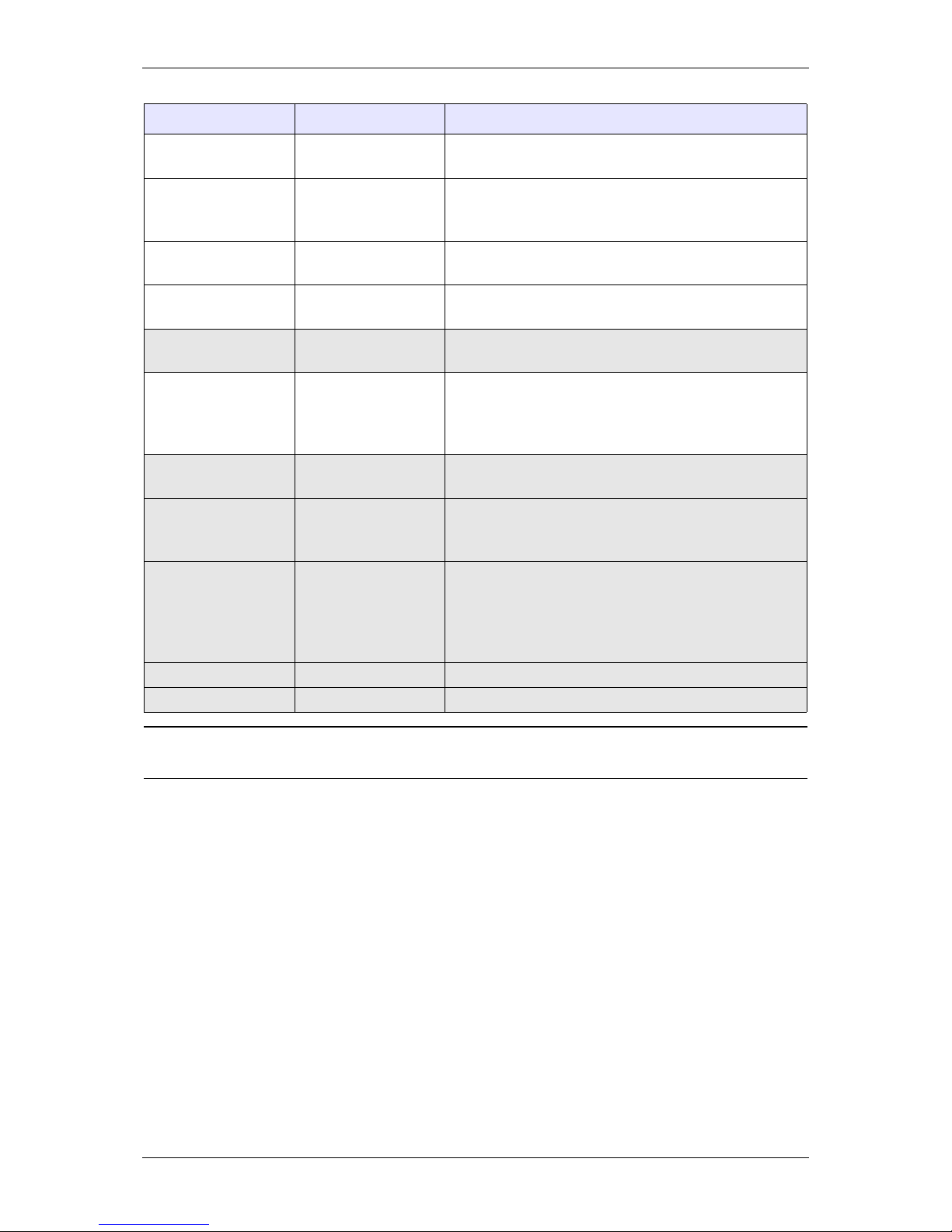
The RMC sentance structure structure is:
$ - - RMC,hhmmss.ss, A,4925.345,N,yyyyy.yy,a,x.x, x.x,ddmmyy,x.x,a*hh<CR><LF>
sentence part information type Definition
- - GPS receiver ID
hmmss.ss time (UTC) hh = hours : two fixed digits
mm = minutes : two fixed digits
ss.ss = seconds : two fixed digits plus two optional decimal points
A status A navigation receiver warning.
A = valid data
V = invalid data
4925.345 latitude 49 degrees : two fixed digits
25.345 minutes : two fixed digits plus up to three
optional decimal points
Page 11
March 2003 M2303-00-P00-805 11
Note: The shaded rows define the sentence segments that are not sent by this application of the RMC
sentence format.
N latitude reference N = north
S = south
12345.123 longitude 123 degrees : three fixed digits
45.123 minutes : two fixed digits plus up to three
optional decimal points
W longitude reference E = east
W = west
xxx speed over ground
(knots)
variable length field with up to three digits
yyy.y course over ground
(degrees true)
variable length field with up to three digits plus one decimal point. Not sent in the AVL report
ddmmyy date dd = day : two fixed digits
mm = month : two fixed digits
yy = year : two fixed digits
Only dd (day) sent in AVL report
020.3 magnetic variation 20.3 degrees magnetic variation
Not sent in the AVL report
E magnetic variation
reference
E = east : subtracts from the True course
W = west : adds to the True course
Not sent in the AVL report
*hh checksum * is a delimiter only
cc = checksum calculated as a 8-bit exclusive OR (no
start or stop bits) of all characters in the sentence
between the ‘$’ and the ‘*’. All ‘,’ delimiters are counted.
Not sent in the AVL report
<CR> carriage return Not sent in the AVL report
<LF> line feed Not sent in the AVL report
sentence part information type Definition
Page 12

12 M2303-00-P00-805 March 2003
5 Programming the A76
Before the A76 can operate, the radio must be configured correctly. The PROGRAM command is used to set
up the default configuration of the A76. An Tait PC application is available for this.
As the serial port of the A76 is expecting NMEA data, the programming command must be in NMEA type
format. For this purpose four new Tait proprietary NMEA messages have been created:
• PTPGM - for programming the database configuration
• PTWDB - response from the A76 to a PTPGM message
• PTRDB - for reading the database configuration
• PTDAT - response from the A76 to a PTRDB message
The NMEA PROGRAM command has the format :
$PTPGM [ITEM1] , [ITEM2] , [ITEM3] , [ITEM4] , [ITEM5] , [ITEM6] , [ITEM7] , [ITEM8] , [ITEM9] , [ITEM10]
[PARAMETER] Function
[ITEM1] A76 Configuration flags. Two ASCII hex characters to represent the following 1 byte of
A76 configurational information.
Bit 1 and Bit 0 Baud Rate : default = 10
Selects the baud rate of the A76 serial port.
00 : 1200 bps
01 : 2400 bps
10 : 4800 bps
11 : 9600 bps
Bit 2 PTT ANI Report : default = 0
If enabled, an ANI report is sent whenever the PTT is pressed. Refer to PTT Activated
AVL Reporting.
0 : No ANI report
1 : ANI report Sent
Bit 3 Over-Air Baud Rate : default = 0
0 : 1200 bps
1 : 2400 bps (Note: the Tait Orca does not support 2400 baud)
Bit 4 FFSK Tone Blanking : default = 0
If enabled, the speaker is muted if valid FFSK data is detected. Refer to FFSK Tone
Blanking.
0 : Tone Blank disabled
1 : Tone Blank enabled
Bit 5 AUX Control : default = 0
If set to 0, control of the AUX (RS232 CTS) output line is allowed. Refer to Auxiliary
Output Control.
0 : AUX Control allowed
1 : AUX Control not allowed
Bit 6 Emergency Mode : default = 0
If set to 0, the Emergency switch (RS232 RTS) input line will trigger Emergency mode.
0 : Emergency switch detected
1 : Emergency switch not detected
Bit 7 PTT Edge for ANI Report : default = 0
0 : ANI report sent on PTT PRESS
1 : ANI report sent on PTT RELEASE
Page 13

March 2003 M2303-00-P00-805 13
[ITEM2] AVL Report Delay Time : default = 10h (1600ms)
Two ASCII hex characters.
The time that the A76 delays after receiving an Poll command until it sends back the
response SDM.
Range : 01 to FFh (25600) in steps of 100 ms. Refer to the section.
[ITEM3] SDM Lead In Delay : default = 10h (320ms
Two ASCII hex characters.
The Lead In Delay time of data transmission is the time between the T201X radio
receiving data and keying-up the transmitter, and the A76 sending the data.
Range : 02 to FFh (255) in steps of 20 ms.
[ITEM4] Power-up Channel : default = 01h (channel 1)
Two ASCII hex characters to set the channel the selected when the radio powers-up.
Range : 01 to 04 (for T2010), or 01 to 24 (for T2015).
[ITEM5] Data ID : default = 00008001h
Eight ASCII hex characters to represent the radio ID used when receiving an SDM.
Any ASCII char is valid.
“
* “ is the wildcard for any character. e.g. 12**5678.
[ITEM6] Emergency AVL Report Count : default = 03h
Two ASCII hex characters to set the number of AVL reports sent once Emergency mode
has been activated.
Range : 00 to FFh (255), if 00 then the Emergency AVL reports are sent indefinitely.
[ITEM7] Emergency AVL Report Period : default = 05h (5 seconds)
Two ASCII hex characters to set the interval between consecutive AVL reports once
Emergency mode has been activated.
Range : 00 to 3Ch (60), in steps of 1 second.
[ITEM8] Group Delay Time : default = 1000h (4096 ms)
Four ASCII hex characters to set the idle period before an AVL report is sent following
a Group Poll.
Range : 0000 to FEFFh (65279), in steps of 1 ms
[ITEM9] Preset AVL Despatcher Address : default = 00008000
Eight ASCII hex characters to represent the default radio ID used to send AVL reports
to.
Any ASCII char is valid.
“
* “ is the wildcard for any character. e.g. 12**5678.
[ITEM10] Software Version
Eight ASCII hex characters to represent the software version of the A76 firmware.
Any ASCII char is valid.
Always set to 2303A1xx, where xx is the version number.
Page 14
14 M2303-00-P00-805 March 2003
6 Operation Sequences
Polling the Remote AVL radio
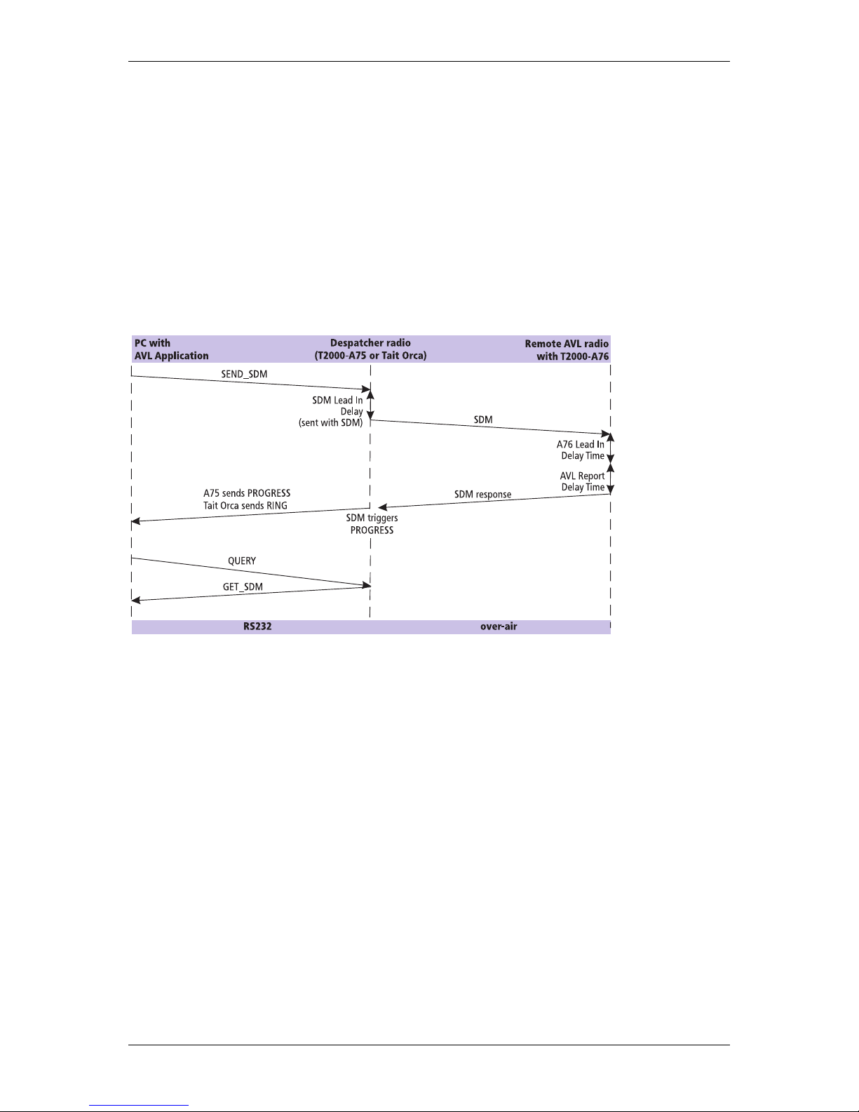
A simple AVL Poll is sent from the PC AVL application to the remote AVL radio. The remote radio automatically
responds with an AVL report.
The AVL Poll command is sent by the despatcher radio using a SEND_SDM command. The SDM contains
instructions about sending the AVL report to either the default address (defined in the A76 configuration) or
to a specified address sent with the command.
CCDI format : [IDENT] [SIZE] [PARAMETERS] [CHECKSUM] <CR>
SEND_SDM format : s [LEAD_IN_DELAY] [DATA_MESSAGE_ID] [COMMAND] [DATA] [CHECKSUM] <CR>
Group Poll
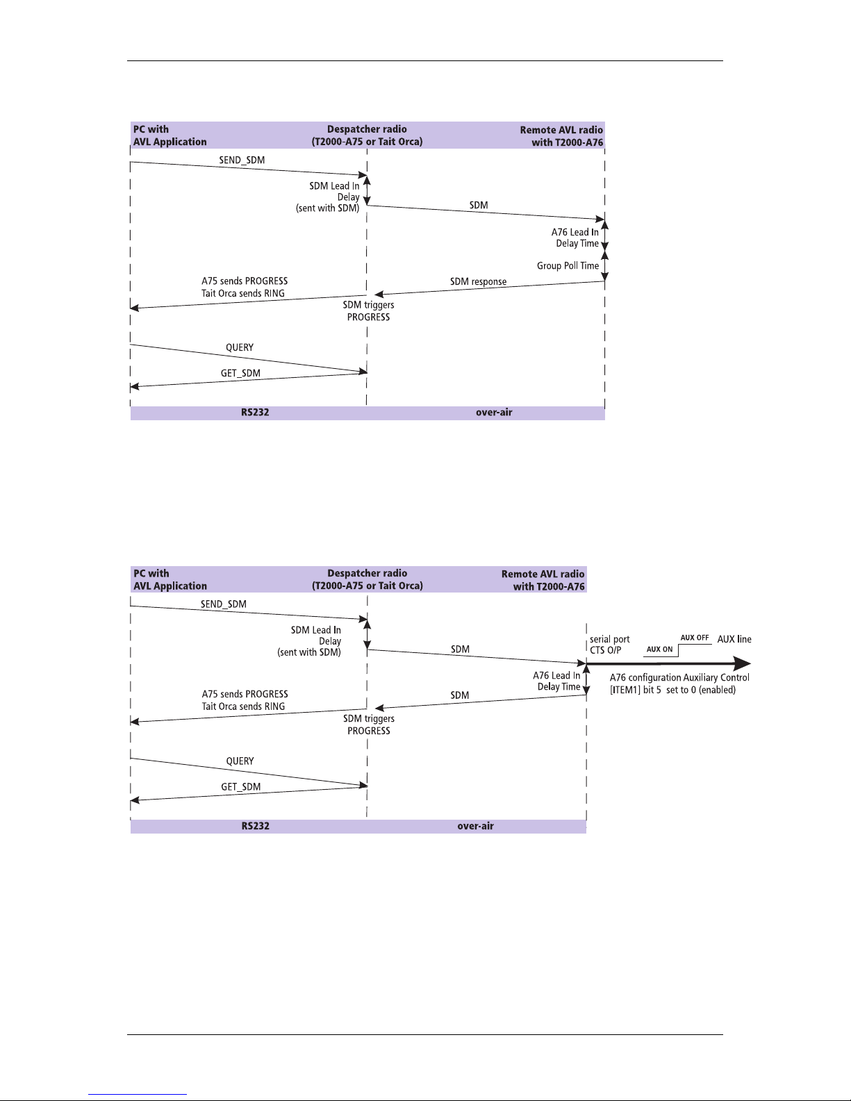
Polling of multiple radios can be done more efficiently by using a Group Poll. A Group Poll is sent by inserting
a wildcard into the [DATA_MESSAGE_ID] part of the SEND_SDM command. The [DATA_MESSAGE_ID] is an
8-character string representing the SDM Data ID of the radio to which the SDM is sent. It can contain any
alphanumeric characters and * can be inserted as the wildcard for any character. e.g. 12**5678
When a radio receives a SDM message, the Data ID is checked against the ID entered in the radio database. If
the Data ID matches, the radio returns an AVL report. If the Data ID does not match then the SDM is ignored.
When a Group Poll is sent, all remote radios that are part of the group will respond with an AVL report. The
idle time before the AVL report is the Group Delay Time set by the A76 configuration or the Program Database
command.
Page 15
March 2003 M2303-00-P00-805 15
Auxiliary Output Control
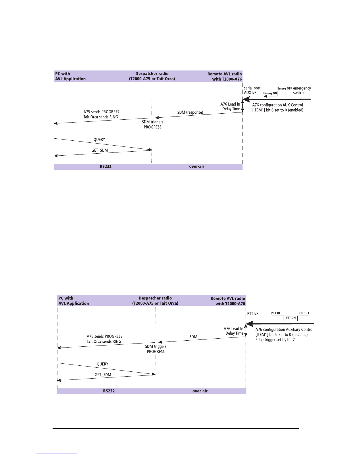
The auxiliary output from the A76 uses the RS232 CTS line on the A76 serial port to switch external devices
on or off. It can be remotely controlled by the despatcher radio by sending a AUX ON or AUX OFF message.
This feature can be enabled or disabled by the A76 configuration.
Page 16
16 M2303-00-P00-805 March 2003
Emergency Mode Activation
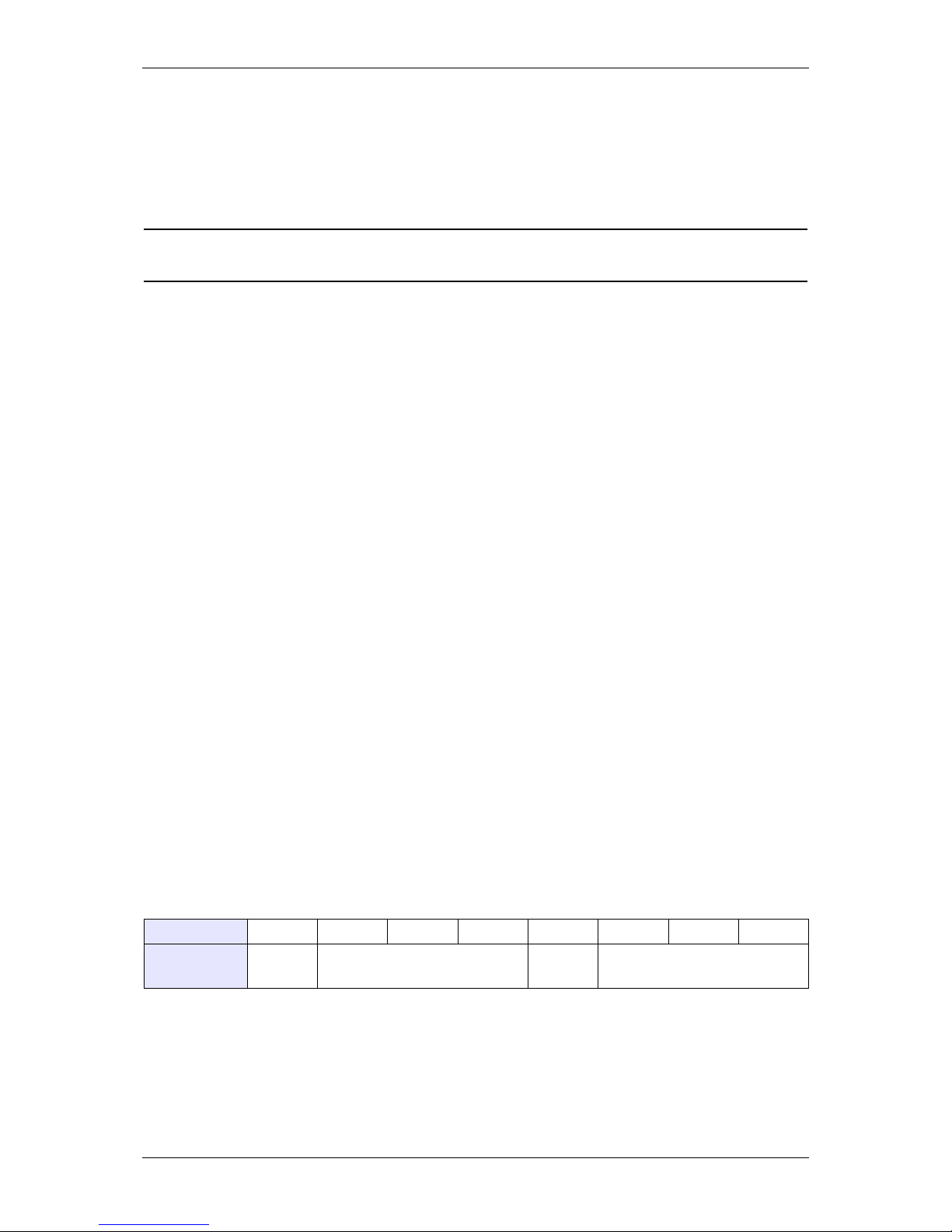
An emergency switch can be connected to the RS232 RTS input on the A76 serial port. When the switch is
activated, the AVL radio sends an Emergency AVL report to the despatcher radio.
The operation of Emergency mode is controlled by the following configuration items - refer to the A76
Configuration section:
• Emergency AVL report count - the number of AVL reports sent after an emergency switch activation.
• Emergency AVL report period - the idle time between AVL reports sent after an emergency switch activation
• The despatcher address the address that the AVL report is sent to
The Emergency mode feature can be enabled or disabled by the A76 configuration.
PTT Activated AVL Reporting
The A76 can be configured to send an unsolicited AVL report each time the PTT is pressed or released. Refer
to the A76 Configuration section. If the radio is already transmitting an AVL report when the PTT is pressed
the current transmission is continued and no further AVL report is sent for that particular PTT press.
Page 17
March 2003 M2303-00-P00-805 17
7 Commands to the Remote Radio
Commands to the remote radio are sent using the SEND_SDM CCDI command. It has the format :
s [LEAD_IN_DELAY] [DATA_MESSAGE_ID] [COMMAND] [DATA]
Notes: The [DATA] field is only sent with some commands.
The [COMMAND] and [DATA] fields are limited to a combined length of 32 hex characters.
The SEND_SDM is sent by the central control AVL application to the despatcher radio, then, after the specified
SDM Lead In Delay, over-air to the remote AVL radio.
‘ s ‘
‘ s ‘ is sent as a single ASCII hex character and represents the SEND_SDM command.
[LEAD_IN_DELAY]
The SDM Lead In Delay is two ASCII hex characters representing the delay between radio transmitter key-up
and the start of data transmission. The range that can be entered is 00 to FF.
The Lead In Delay is calculated by multiplying the number by 20 ms. A minimum of at least 100 ms of Lead In
Delay is required, so 00 to 04 will always be treated as 05. This corresponds to a Lead In Delay between 100
ms and 5.1 seconds, in steps of 20 ms. Refer to the Polling the Remote AVL radio section.
[DATA_MESSAGE_ID]
The [DATA_MESSAGE_ID] is an 8-character string representing the SDM Data ID of the radio to which the
SDM is sent. It can be any alphanumeric characters. “
* “ is the wildcard for any character. e.g. 12**5678
The first four bytes are generally the fleet ID, the second four the radio ID.
When a radio receives a SDM message, the Data ID is checked against the ID entered in the radio
configuration database. If the Data ID matches, the radio sends a response to indicate this.
If the Data ID does not match then the SDM data is ignored.
[COMMAND]
The [COMMAND] part of the SEND_SDM contains the SDM text with commands to the remote radio.
The table below shows the structure of the [COMMAND] byte.
Bit Bit 7 Bit 6 Bit 5 Bit 4 Bit 3 Bit 2 Bit 1 Bit 0
Function 0 Command Type Return
Address
Parameter
Page 18
18 M2303-00-P00-805 March 2003
[MESSAGE]
first byte
Function
Bit 0 - 2 Parameter
The Parameter is set depending on the Command Type that is sent. Refer to the
table below for the Parameter options.
Bit 3 Return Address
0 : the AVL report is sent to the default despatcher address
1 : the AVL report is sent to the return address specified.
Bit 4 - 6 Command Type
000 : Poll - poll for a AVL report from the remote radio
001 : Read Database - read a database item from the remote radio
010 : Program Database - program database item into the remote radio
011 : Control AUX - used for controlling the AUX to the remote radio
100 - 110 : reserved
111 : Reset - used for resetting the remote radio
Bit 7 Always 0
Page 19

March 2003 M2303-00-P00-805 19
Command Type
Bits 4,5 and 6
C Parameters
Bits 0,1 and 2
A76 Action / Response
Poll
000
000 : poll the AVL report. Always set to 000.
001 - 111 : the command will be ignored
If a return address is sent, it is sent in the [DATA]
bytes.
AVL report is sent
Examples:
[COMMAND] = 00h = 0000 0000 Send AVL report to the
default despatcher address
[COMMAND] = 08,30,30,30,30,30,38,30,30h
08h = 0000 1000 followed by the address where
30h is ASCII for 0 and 38h is ASCII for 8
Send AVL report to the
return address 00000800
Read Database
001
000 : read the software version
001 : read the Group Delay Time
010 - 111 : the command will be ignored
If a return address is sent, it is sent in the [DATA]
bytes.
A ‘Read Database ACK’ is
sent back followed by the
value of the database item
Examples:
[COMMAND] = 10h = 0001 0000 Read the software version
and send ACK (90h) plus
the result to the default
despatcher address
[COMMAND] = 19,30,30,30,30,30,38,30,30h
19h = 0001 1001 followed by the address
where 30h is ASCII for 0 and 38h is ASCII for 8
Read the Group Delay Time
and send ACK (91h) plus
the result to the return
address 00000800
Program Database
010
001 : program the Group Delay Time
010 - 111 : the command will be ignored
If a return address is sent, it is sent in the [DATA]
bytes as is the Group Delay Time data. The address
precedes the Group Delay Time.
The Group Delay Time is
programmed into the database and a ‘Program Database with Group Delay
Time ACK’ (A1) is sent back
Examples:
[COMMAND] = 21,00,00h
21h = 0010 0001 followed by two bytes of Group
Delay Time in ms, where 00 00h = 0ms.
Program the Group Delay
Time with the value 0ms
and send back a ‘Program
Database with Group Delay
Time ACK’ (A1) to the
default despatcher address
. [COMMAND] = 29,30,30,30,30,30,38,30,30,FF,00h
29 = 0010 1001 followed by the address
where 30h is ASCII for 0 and 38h is ASCII for 8 and
then two bytes of Group Delay Time in ms, where
FF 00h = 65,280ms (65.28 seconds).
Program the Group Delay
Time with the value
65,280ms and send a ‘Program Database Group
Delay Time ACK’ (A1h) to
the return address
00000800
Page 20

20 M2303-00-P00-805 March 2003
[DATA]
The [DATA] field is only sent if return address information and/or the Group Delay Time data is required to be
sent. Refer to the previous table for details.
Note: Addresses
The default despatcher address is set during the configuration programming. Refer to the
A76 Configuration section.
Address come in the form of eight ASCII hex characters. Any ASCII character is valid and “
* “
is the wildcard for any character. e.g. 12**5678.
Command Type
Bits 4,5 and 6
Parameters
Bits 0,1 and 2
A76 Action / Response
Control AUX
011
000 : sets the AUX (CTS) signal to ON
001 : sets the AUX (CTS) signal to OFF
010 - 111 : the command will be ignored
If a return address is sent, it is sent in the [DATA]
byte.
A ‘Control AUX ACK’ is sent
back
Examples:
[COMMAND] = 30h = 0011 0000 Sets the AUX (CTS) signal
at the remote radio to ON
and sends a ‘Control AUX
ON ACK’ (B0h) to the
default despatcher address
[COMMAND] = 39,30,30,30,30,30,38,30,30h
39h = 0011 1001 followed by the address
where 30h is ASCII for 0 and 38h is ASCII for 8
Sets the AUX (CTS) signal
at the remote radio to OFF
and sends the message
‘Control AUX OFF ACK’
(B1h) to the return address
00000800
Reset Radio
111
000 : Reset the remote radio only
001 : Reset the radio and initialise the
database with factory settings
010 - 111 : the command will be ignored
no response
Examples:
[COMMAND] = 70h = 0111 0000 Resets the remote radio
[COMMAND] = 71h = 0111 0001 Resets the remote radio
and initialises with values
from the firmware
Page 21
March 2003 M2303-00-P00-805 21
8 Responses from the Remote Radio
Commands sent to the remote AVL radio generally require a response. The Reset command is the only
exception to this. The response from the remote radio is sent as an SDM. It has the format :
[RESPONSE] [DATA]
The SDM is sent by the remote AVL radio over-air to the despatcher radio where it is then retrieved by the
AVL application using the GET_SDM CCDI command.
The [RESPONSE] byte is specific to the command that was sent. The [DATA] is either an AVL report or other
data determined by the response type.
[RESPONSE]
The [RESPONSE] is a one byte responses to the command from the AVL application.
The table below shows the structure of the [RESPONSE].
[RESPONSE]
Bit
Bit 7 Bit 6 Bit 5 Bit 4 Bit 3 Bit 2 Bit 1 Bit 0
Function 1 Response Type Radio Status / ACK Parameter
[RESPONSE] parts Function
Byte 1 : Bits 0 - 3 Radio Status / ACK Parameters
These bits are set depending on the Response Type being sent. Refer to the table
below for the options.
Byte 1 : Bits 4 - 6 Response Type
000 : AVL Report - send the AVL report in response to the Poll
command. The AVL report contains up to 17 8-bit bytes of data.
001 : Read Database ACK - sent in response to a Read Database
command
010 : Program Database ACK - sent in response to a Program
Database command.
011 : Control ACK- sent in response to the Control AUX command
100 - 111 : reserved
Byte 1 : Bit 7 Always 1
Page 22
22 M2303-00-P00-805 March 2003
Response Type
Bits 4,5 and 6
Radio Status / ACK Parameters
Bits 0,1,2 and 3
AVL Report
000
Bits 0 and 1 are used to send error handling information, where
00 : AVL report sent with new data OK
01 : AVL report sent with old data
10 : GPS receiver down, no data sent, no AVL report to be sent
11 : Data format error, no AVL report to be sent
Bit 2 is used it send Emergency mode status, where
0 : Emergency Mode OFF
1 : Emergency Mode ON
Bit 3 is used to send the AUX (CTS) signal status, where
0 : AUX (CTS) signal OFF
1 : AUX (CTS) signal ON
Examples:
[RESPONSE] = 08 [AVL_REPORT]h
88h = 1000 1000
Interpretation: AVL report will follow with new data, Emergency mode is OFF and
the AUX signal is ON. Refer to the AVL Report section for details of the AVL
Report.
Read Database ACK
001
0000 : sends the software version
0001 : sends the Group Delay Time
The returned data comes immediately after the ACK Parameters.
Examples:
If a Read Database command is sent to read the software version, the response
is:
[RESPONSE] = 90,32,33,30,33,41,35,32,30h
90h = 1001 0000 followed by the software version 2303A520 as 8 bytes of ASCII
If a Read Database command is sent to read the Group Delay Time, the response
is:
[RESPONSE] = 91,00,00h
91h = 1001 0001 followed by the Group Delay Time of 00ms
Program Database
ACK
010
0001 : the Group Delay Time has been
programmed into the database
Examples:
[RESPONSE] = A1h = 1010 0001 is sent to acknowledge that the Group Delay
Time has been programmed
Control AUX ACK
011
0000 : the AUX (CTS) signal to has been set to
ON
0001 : the AUX (CTS) signal has been set to
OFF
Examples:
[RESPONSE] = B0h = 1011 0000 is sent to acknowledge AUX ON
[RESPONSE] = B1h = 1011 0001 is sent to acknowledge AUX OFF
Page 23
March 2003 M2303-00-P00-805 23
[DATA]
The [DATA] field contains either an AVL Report or other data dependent on the type of acknowledgement
being sent. Refer to the previous table for acknowledgement details.
AVL Report
Note: If no AVL data is received within 20 seconds or a format error occurs in the RMC data (incorrect check-
sum), then the AVL report is not send. Bits 0 and 1 in the [RESPONSE] are set to 10 or 11 and only the response
and the radio ID bytes are sent.
Note: If a digit is not convertible to BCD, then its value is set to ‘F’.
[AVL_REPORT] MSB LSB Description
Byte 2 Radio ID ‘1’ Radio ID ‘2’ four digit BCD number - last four digits of
radio ID from configuration database
Byte 3 Radio ID ‘3’ Radio ID ‘4’
Byte 4
1HHHH: Hour - two digit BCD number
Byte 5
1MMMM: Minute - two digit BCD number
Byte 6
1SSSS: Second - two digit BCD number
Byte 7
1F LdF: Latitude Ref bit 4: 0=N, 1=S
bit 5: 0=E, 1=W
Ld: Latitude degrees - two digit BCD number
Byte 8 Ld
1LmLd: Latitude degrees cont.
Lm: Latitude minutes - two digit BCD number
Byte 9 Lm Ls Lm: Latitude minutes cont.
Ls: Latitude decimal points - two digit BCD
number
Byte 10 Ls Ls: Latitude decimal points cont.
Byte 11
1 0 1GdGd: Logitude degrees - three digit BCD
number
Byte 12 Gd
1GmGd: Longitude degrees cont.
Gm: Logitude minutes - two digit BCD
number
Byte 13 Gm Gs Gm: Longitude minutes cont.
Gs: Logitude decimal - three digit BCD
number
Byte 14 Gs Gs: Logitude decimal cont.
Byte 15
1 0DDDD: Day - two digit BCD number
Byte 16 Vk Vk: Speed over ground (knots) - three digit
BCD number
Byte 17 Vk Vp Vk: Speed over ground cont.
Vp: Speed over ground decimal - one digit
BCD number
Page 24
24 M2303-00-P00-805 March 2003
9 CCDI Reference
The CCDI data protocol is used to send and receive commands from a CCDI capable modem in a radio.
The A76 modem in the remote AVL radio communicates with the despatcher radio using CCDI commands. To
send and recieve messages using the over-air CCDI protocol, the despatched radio must have a CCDI interface
(e.g. Tait Orca, Tait Radio Modem or T201x with an A75 fitted).
The over-air CCDI protocol is not described as the CCDI interface at the despatcher radio described in this
manual is the only way to communicate with the A76 radio.
CCDI Message Format
All CCDI message packets take the general form:
[IDENT] [SIZE] [PARAMETERS] [CHECKSUM] <CR>
Restrictions
• Where numeric values are represented in ASCII-hex notation (two characters per byte), characters A to F
are upper case.
• The minimum length of a command packet is 5 characters. For example q002F is the QUERY command
where [SIZE] = 00 as there is no [PARAMETERS] field required.
• The maximum length of the [PARAMETERS] field is 42 characters. The maximum length of the command
packet is therefore 47 ([SIZE] = 2F) characters.
Calculating the CCDI [CHECKSUM]
Note: This is not required if an AVL PC application such as is used to send commands.
[CHECKSUM] is calculated by applying the following algorithm:
1. Take the modulo-2 sum of all message bytes preceding [CHECKSUM].
2. Retain bits 0 to 7, discarding any higher order bits resulting from the summation.
3. Form the two’s complement of the remainder.
4. Convert the binary number into two ASCII-hex digits, MSD first.
Field Description
[IDENT] The message identifier. Identifiers are single ASCII characters (lower-case alphabetical)
which categorise the message type.
[SIZE] The number of characters which make up the [PARAMETERS] field. [SIZE] is an 8-bit
number expressed in ASCII-hex notation (two characters).
[PARAMETERS] An optional field, depending upon the command. Parameter values are generally char-
acter strings unless explicitly stated otherwise. Parameter type is dependent upon the
command - there is no explicit type definition.
[CHECKSUM] An 8-bit checksum of the [IDENT], [SIZE] and [PARAMETERS] fields. Expressed in two
character ASCII-hex notation.
<CR> The carriage return packet terminator.
Page 25

March 2003 M2303-00-P00-805 25
Checksum Example
s0D050800TESTHi!DA
1. Take the modulo-2 sum of all message bytes preceding [CHECKSUM].
• s = 73h, 0 = 30h, D = 44h etc. therefore the modulo-2 sum is:
73 + 30 + 44 + 30 + 35 + 30 + 38 + 30 + 30 + 54 + 45 + 53 + 54 + 48 + 69 + 21 = 426h
2. Retain bits 0 to 7, discarding any higher order bits resulting from the summation.
• 26h
3. Form the two’s complement of the remainder.
• 26h = 0010 0110
two’s complement = 1101 1010
4. Convert the binary number into two ASCII-hex digits, MSD first.
• 1101 1010 = DA
The following CCDI commands are sent between the PC AVL application and the despatcher radio.
Page 26
26 M2303-00-P00-805 March 2003
GET_SDM (despatcher radio to PC)
Solicited.
The GET_SDM message is sent to the PC in response to a QUERY command. The modem sends the SDM text
message which is saved in the EEPROM.
It has the format :
s [SDM_DATA]
Example
An example of a ‘Get SDM’ message is: s05Hello34
PARAMETER Function
[SDM_DATA] This can be a maximum of 32 characters. If there is any buffered SDM data in the
EEPROM, the SDM data is sent to the PC. If there is no data available then the
command is sent with no [PARAMETERS] field.
Message Field Parameter
A76
Response
[IDENT] GET_SDM. s
[SIZE] Size of parameter field 05
[PARAMETERS] [SDM_DATA]; the SDM text message from the A76 EEPROM Hello
[CHECKSUM] The checksum for the message string, calculated by the A76 34
Page 27
March 2003 M2303-00-P00-805 27
PROGRESS (despatcher radio to PC)
Unsolicited.
The PROGRESS message advises the PC of modem status when some significant change of state in the radio
occurs (typically during call processing).
It has the format :
p [PTYPE] [PARA1]
[PARAMETER] Function
[PTYPE] A two-digit string representing a decimal number in the range of 00 to 99 which
can identify the progress message category.
PARA1] A single-digit number representing the message status.
[PTYPE] = 05 Receiver Busy. This message indicates that the receiver has detected an RF sig-
nal on the current channel. This message is sent when the current channel
becomes busy.
[PTYPE] = 06 Receiver Not Busy. This message indicates that the receiver no longer detects
an RF signal on the current channel. This message is sent when the current channel becomes available.
[PTYPE] = 07 PTT Mic Activated. This message indicates that the PTT has been pressed. This
message is sent whenever the PTT is pressed in an attempt to transmit.
[PTYPE] = 08 PTT Mic Deactivated. This message indicates that the PTT has been released.
This message is sent whenever the PTT is released after attempting to transmit.
[PTYPE] = 1D SDM ACK. This message indicates that an SDM ACK was received after the last
SDM sent. This only occurs if the modem receiving the SDM has SDM Auto ACK
enabled.
[PARA1] = 0 NO ACK RECEIVED
[PARA1] = 1 ACK RECEIVED
[PTYPE] = 1E SDM Data Received. This message indicates that the A76 received valid SDM
data with the correct SDM Data ID.
[PARA1] = 0 No SDM text message was included in the SDM. The [MESSAGE]
parameter was empty
[PARA1] = 1 The SDM included an SDM text message.
Page 28
28 M2303-00-P00-805 March 2003
Example
An example of an ‘Progress’ message is: p0207C7
Message Field Parameter
A76
Response
[IDENT] PROGRESS. p
[SIZE] Size of parameter field 02
[PARAMETERS] [PTYPE] = 07; the PTT mic has been activated by the FUNCTION
command
07
[CHECKSUM] The checksum for the message string, calculated by the modem C7
Page 29
March 2003 M2303-00-P00-805 29
QUERY (PC to despatcher radio)
The QUERY command requests the modem to respond with data. The data can contain several types of
information.
It has the format :
q [QUERY_TYPE]
Example
An example of a ‘Query’ message is: q012FC
[PARAMETER] Function
[QUERY_TYPE] A single ASCII hex character representing the query type.
[QUERY_TYPE] = 0 Query Model message. The T201X radio and CCDI information is returned to
the PC as a MODEL message.
[QUERY_TYPE] = 1 Query SDM message. The SDM message is returned to the PC as a GET_SDM
message.
[QUERY_TYPE] = 2 Query Database message
[QUERY_TYPE] = 3 Query S/W Version message
[QUERY_TYPE] =
Blank
Same as [QUERY_TYPE] = 0
Message Field Parameter
Entered at
terminal
[IDENT] QUERY. q
[SIZE] Size of parameter field 01
[PARAMETERS] [QUERY_TYPE] = 2 to interrogate the database for the A76 configura-
tion
2
[CHECKSUM] Refer to the Calculating the CCDI [CHECKSUM] section FC
Page 30

30 M2303-00-P00-805 March 2003
SEND_SDM (PC to despatcher radio)
The SEND_SDM command requests the modem to send a Short Data Message (SDM). The PC sends the SDM
directly to the A76, and the T201X immediately keys up the transmitter. After the specified SDM Lead In Delay
the modem sends the SDM.
It has the format :
[LEAD_IN_DELAY] [DATA_MESSAGE_ID] [COMMAND] [DATA]
[PARAMETER] Function
[LEAD_IN_DELAY] SDM Lead In Delay. Two ASCII hex characters representing the SDM Lead In
Delay between radio transmitter key-up and the start of data transmission. The
range that can be entered is 00 to FF.
The Lead In Delay is calculated by multiplying the number by 20 ms.
A minimum of at least 100 ms of Lead In Delay is required, so 00 to 04 will
always be treated as 05. This corresponds to a Lead In Delay between 100 ms
and 5.1 seconds, in steps of 20 ms. Refer to the Polling the Remote AVL radio
section.
[DATA_MESSAGE_ID] SDM Data ID. An 8-character string representing the SDM Data ID of the
radio to which the SDM is sent. It can be any alphanumeric characters. “
* “ is
the wildcard for any character. e.g. 12
**5678
When a radio receives a SDM message, the Data ID is checked against the ID
entered in the radio database (using the PROGRAM command). If the Data ID
matches, the received SDM data is stored and the radio sends a PROGRESS
command to indicate this.
If the Data ID does not match then the SDM data is ignored.
[MESSAGE] SDM text. Maximum 32 characters of SDM data. [MESSAGE] is optional.
 Loading...