

Page 1

Tait Orca 5000 Portable Radios
Service Manual
June 2003
IPN: M5000-00-105
Page 2

Preface
Contacting Tait Electronics Ltd
The contact details for your nearest Tait Electronics regional office, can be found on the Tait
Website: http://www.taitworld.com/
Enquiries and comments
If you have any enquiries regarding this manual, or any comments, suggestions and notifications
of errors, please contact Customer Support, Tait Electronics Ltd, Christchurch, New Zealand, or
refer to the Tait Website.
Conventions
Throughout this manual, the following conventions are used:
■ Names of software screen, field and menu names are referred to in bold sans serif font. For
example:
Check that the information in the Radio Model fields (Specifications screen) is correct.
■ The xxxx-character is used as a wildcard in product codes and part numbers, to indicate unspec-
ified characters.
Disclaimer
There are no warranties extended or granted by this manual. Tait Electronics Ltd accepts no
responsibility for damage arising from use of the information contained in the manual or of the
equipment and software it describes. It is the responsibility of the user to ensure that use of such
information, equipment and software complies with the laws, rules and regulations of the applicable jurisdictions.
Updating equipment and manuals
In the interests of improving performance, reliability or servicing, Tait Electronics Ltd reserve the
right to update their equipment and/or manuals without prior notice.
Copyright
All information contained in this manual is the property of Tait Electronics Ltd. All rights are
reserved. This manual may not, in whole or in part, be copied, photocopied, reproduced, translated, stored, or reduced to any electronic medium or machine-readable form, without prior written
permission from Tait Electronics Limited. All trade names referenced are the service mark, trademark or registered trademark of the respective manufacturers.
ii June 2003 IPN: M5000-00-105
Page 3

Publication history
Publication Date Product Code
May 2001 M5000-00-100
June 2001 M5000-00-101
September 2001 M5000-00-102
May 2002 M5000-00-103
September 2002 M5000-00-104
June 2003 M5000-00-105
June 2003 IPN: M5000-00-105 iii
Page 4

iv June 2003 IPN: M5000-00-105
Page 5

Contents
Part A: Introduction
Servicing Tait Orca 5000 portable radios
Servicing Tait Orca 5000 portable radios .................................................................................
Servicing Tait Orca 5000 portable radios Servicing Tait Orca 5000 portable radios
WWW technical support ..................................................................................................................... A-3
What does this manual contain? .......................................................................................................... A-3
Calibration service kit .......................................................................................................................... A-3
Programming kit .................................................................................................................................. A-4
The Tait Orca 5000 series of portable radios
The Tait Orca 5000 series of portable radios ............................................................................
The Tait Orca 5000 series of portable radios The Tait Orca 5000 series of portable radios
The Tait Orca product code ................................................................................................................. A-5
Operating instructions ......................................................................................................................... A-5
Accessories ........................................................................................................................................... A-5
Important information
Important information .............................................................................................................
Important information Important information
Basic servicing precautions .................................................................................................................. A-9
Programming ....................................................................................................................................... A-9
............................................................................................................. A-9
..........................................................................................................................................................................................................................
................................................................................. A-3
..................................................................................................................................................................
............................................................................ A-5
........................................................................................................................................................
A-3
A-3A-3
A-5
A-5A-5
A-9
A-9A-9
Calibrating ......................................................................................................................................... A-10
Test facilities ...................................................................................................................................... A-10
Basic maintenance ............................................................................................................................. A-10
Servicing Intrinsically Safe radios
Servicing Intrinsically Safe radios ...........................................................................................
Servicing Intrinsically Safe radios Servicing Intrinsically Safe radios
Intrinsically Safe radios ...................................................................................................................... A-11
IS PCB servicing requirements ........................................................................................................... A-11
FM approval ....................................................................................................................................... A-11
FM approved products ....................................................................................................................... A-11
FM approved accessories ................................................................................................................... A-11
........................................................................................... A-11
......................................................................................................................................................................................
Part B: Radio specifications and circuit descriptions
Radio specifications
Radio specifications ..................................................................................................................
Radio specifications Radio specifications
General specifications ........................................................................................................................... B-3
Receiver performance ........................................................................................................................... B-3
Transmitter performance ..................................................................................................................... B-4
TOP-Axxxx 66-88MHz radio specifications.......................................................................................... B-5
.................................................................................................................. B-3
....................................................................................................................................................................................................................................
A-11
A-11A-11
B-3
B-3B-3
TOP-Bxxxx 136-174MHz radio specifications ...................................................................................... B-6
TOP-Cxxxx 174-225MHz radio specifications ...................................................................................... B-7
TOP-Gxxxx 336-400MHz radio specifications...................................................................................... B-8
TOP-Hxxxx 400-470MHz radio specifications...................................................................................... B-9
TOP-Ixxxx 450-530MHz radio specifications ..................................................................................... B-10
June 2003 IPN: M5000-00-105 v
Page 6

TOP-Jxxxx 806-870MHz radio specifications...................................................................................... B-11
TOP-Kxxxx 896-941MHz radio specifications .................................................................................... B-12
Circuit descriptions
Circuit descriptions .................................................................................................................
Circuit descriptions Circuit descriptions
Transmitter ........................................................................................................................................ B-13
Transmit (Tx) audio ........................................................................................................................... B-13
Receiver .............................................................................................................................................. B-13
Receive (Rx) audio .............................................................................................................................. B-13
DSP .................................................................................................................................................... B-14
Synthesiser and VCO .......................................................................................................................... B-14
Power supplies ................................................................................................................................... B-14
Accessory connector interface ............................................................................................................ B-15
Universal band versus wideband IF filtering ...................................................................................... B-15
................................................................................................................. B-13
..................................................................................................................................................................................................................................
Part C: Diagnostics and fault finding
Test facilities
Test facilities .............................................................................................................................
Test facilities Test facilities
Error codes ........................................................................................................................................... C-3
............................................................................................................................. C-3
..........................................................................................................................................................................................................................................................
B-13
B-13B-13
C-3
C-3C-3
Test commands ..................................................................................................................................... C-5
Calculating the parameters required for test command 101 ................................................................. C-7
Fault finding charts
Fault finding charts ...................................................................................................................
Fault finding charts Fault finding charts
Radio cannot be switched on ................................................................................................................ C-9
Cannot change channel ...................................................................................................................... C-10
No serial communication ................................................................................................................... C-11
Receive faults ...................................................................................................................................... C-12
Cannot transmit ................................................................................................................................. C-13
No transmit audio .............................................................................................................................. C-14
...................................................................................................................C-8
......................................................................................................................................................................................................................................
Part D: Servicing the radio
Servicing the radio
Servicing the radio ...................................................................................................................
Servicing the radio Servicing the radio
Screw head types .................................................................................................................................. D-3
Disassembling the radio
Disassembling the radio ..........................................................................................................
Disassembling the radio Disassembling the radio
Removing the front panel from the chassis ..........................................................................................D-4
Removing the shield sub-assembly from the chassis ............................................................................ D-5
................................................................................................................... D-3
......................................................................................................................................................................................................................................
.......................................................................................................... D-4
....................................................................................................................................................................................................................
C-8
C-8C-8
D-3
D-3D-3
D-4
D-4D-4
Removing the PCB from the chassis .....................................................................................................D-6
Removing the rear panel ......................................................................................................................D-7
Replacing key mechanical and ancillary devices
Replacing key mechanical and ancillary devices ......................................................................
Replacing key mechanical and ancillary devices Replacing key mechanical and ancillary devices
Replacing the lens (Orca 5015/2x/35/40) ...........................................................................................D-8
Replacing the PTT keypad ....................................................................................................................D-8
Replacing the speaker ........................................................................................................................... D-9
vi June 2003 IPN: M5000-00-105
...................................................................... D-8
............................................................................................................................................
D-8
D-8D-8
Page 7

Replacing the LCD display (Orca 5015/2x/35/40) .............................................................................. D-9
Replacing the shield, user interface PCB and polyester dome (Orca 5015/2x/35/40) ....................... D-12
Replacing the antenna connector, channel selector switch and volume control switch ..................... D-12
Replacing the microphone .................................................................................................................D-12
Replacing the battery and speaker contacts .......................................................................................D-12
Replacing the tact switch ....................................................................................................................D-12
Replacing the chassis .......................................................................................................................... D-13
Reassembling the radio
Reassembling the radio ..........................................................................................................
Reassembling the radio Reassembling the radio
Rear panel reassembly and replacing the auxiliary flexible PCB ........................................................ D-14
Fitting the PCB to the chassis and replacing the RF out assembly ...................................................... D-15
Fitting the shield to the chassis .......................................................................................................... D-15
Fitting the front panel to the chassis .................................................................................................. D-16
Spares kits
Spares kits ..............................................................................................................................
Spares kits Spares kits
Information contained in the tables ................................................................................................... D-17
PCB Product Codes ............................................................................................................................ D-17
Orca 5010/11/30 spares kit (TOPA-SP-401G) .................................................................................. D-18
.............................................................................................................................. D-17
............................................................................................................................................................................................................................................................
.......................................................................................................... D-14
....................................................................................................................................................................................................................
D-14
D-14D-14
D-17
D-17D-17
Orca 5035 spares kit (TOPA-SP-402G) .............................................................................................. D-19
Orca 5015/2x/40 spares kit (TOPA-SP-403G)................................................................................... D-20
Orca 5010/11/30 re-skinning kit (TOPA-SP-404) ............................................................................. D-21
Orca 5035 Re-skinning kit (TOPA-SP-405)........................................................................................ D-21
Orca 5020/40 Re-skinning kit (TOPA-SP-406).................................................................................. D-21
Orca 5015/2x/35/40 User Interface PCB and Shield (TOPA-SP-407) ............................................... D-22
Orca 5015/21 Re-skinning kit (TOPA-SP-408).................................................................................. D-22
Part E: Battery packs and chargers
Battery packs
Battery packs .............................................................................................................................
Battery packs Battery packs
Battery shift life ..................................................................................................................................... E-3
Disposing of used nickel-cadmium batteries .........................................................................................E-4
Battery chargers
Battery chargers ........................................................................................................................
Battery chargers Battery chargers
Desktop fast charger
Desktop fast charger ..................................................................................................................
Desktop fast charger Desktop fast charger
Fast charger operation .......................................................................................................................... E-6
Using the fast charger ............................................................................................................................E-9
.............................................................................................................................E-3
..........................................................................................................................................................................................................................................................
........................................................................................................................E-5
................................................................................................................................................................................................................................................
..................................................................................................................E-6
....................................................................................................................................................................................................................................
E-3
E-3E-3
E-5
E-5E-5
E-6
E-6E-6
Repairing the fast charger ...................................................................................................................E-10
Desktop trickle charger
Desktop trickle charger ...........................................................................................................
Desktop trickle charger Desktop trickle charger
Trickle charger operation .................................................................................................................... E-12
Using the trickle charger .....................................................................................................................E-13
Repairing the trickle charger ...............................................................................................................E-13
June 2003 IPN: M5000-00-105 vii
...........................................................................................................E-12
......................................................................................................................................................................................................................
E-12
E-12E-12
Page 8

Troubleshooting ..................................................................................................................................E-14
Multi-charger
Multi-charger ..........................................................................................................................
Multi-charger Multi-charger
Multi-charger operation ......................................................................................................................E-15
Repairing the multi-charger ................................................................................................................E-15
Fuse replacement ................................................................................................................................E-16
.......................................................................................................................... E-15
....................................................................................................................................................................................................................................................
Part F: Accessories
Tait Orca 5000 accessory connector
Tait Orca 5000 accessory connector .........................................................................................
Tait Orca 5000 accessory connector Tait Orca 5000 accessory connector
Screw head types ...................................................................................................................................F-3
Connecting an accessory .......................................................................................................................F-3
Connecting a headset ............................................................................................................................F-5
Accessory connector signal descriptions ...............................................................................................F-6
7.5 mm Accessory adaptor
7.5 mm Accessory adaptor ........................................................................................................
7.5 mm Accessory adaptor 7.5 mm Accessory adaptor
Tait Orca vehicle kit
Tait Orca vehicle kit ................................................................................................................
Tait Orca vehicle kit Tait Orca vehicle kit
Product codes ......................................................................................................................................F-10
Update to the vehicle kit ......................................................................................................................F-10
........................................................................................................ F-8
................................................................................................................................................................................................................
................................................................................................................ F-10
................................................................................................................................................................................................................................
......................................................................................... F-3
..................................................................................................................................................................................
E-15
E-15E-15
F-3
F-3F-3
F-8
F-8F-8
F-10
F-10F-10
Installing a vehicle kit ..........................................................................................................................F-10
Vehicle kit operation ...........................................................................................................................F-10
Vehicle kit specifications .....................................................................................................................F-12
Servicing the vehicle kit ....................................................................................................................... F-13
Spares kits ...........................................................................................................................................F-14
Vehicle kit spares kit (TOPA-SP-301).................................................................................................. F-15
Vehicle kit reskinning kit (TOPA-SP-302)........................................................................................... F-16
Custom modifications ......................................................................................................................... F-17
Vehicle kit circuit descriptions ............................................................................................................F-19
Part G: Additional information
Glossary
Glossary ................................................................................................................................
Glossary Glossary
Accessory connector compatibility
Accessory connector compatibility ..........................................................................................
Accessory connector compatibility Accessory connector compatibility
...................................................................................................................................
................................................................................................................................................................................................................................................................
.......................................................................................... G-8
....................................................................................................................................................................................
... G-3
......
G-3
G-3G-3
G-8
G-8G-8
viii June 2003 IPN: M5000-00-105
Page 9

A
PART
Introduction
This part provides an introduction to servicing Tait Orca 5000
portable radios. It includes an outline of the Tait Orca 5000 range
of products and precautions that should be taken before servicing
Tait Orca 5000 portable radios.
Detailed servicing instructions and information about spare parts
are found in Part D: Servicing the radio.
Contents
Servicing Tait Orca 5000 portable radios
Servicing Tait Orca 5000 portable radios ......................................................
Servicing Tait Orca 5000 portable radios Servicing Tait Orca 5000 portable radios
WWW technical support ...................................................................................... A-3
What does this manual contain? ........................................................................... A-3
...................................................... A-3
............................................................................................................
A-3
A-3A-3
Calibration service kit ........................................................................................... A-3
Programming kit ................................................................................................... A-4
Conventions .......................................................................................................... A-4
The Tait Orca 5000 series of portable radios
The Tait Orca 5000 series of portable radios .................................................
The Tait Orca 5000 series of portable radios The Tait Orca 5000 series of portable radios
The Tait Orca product code ................................................................................... A-5
Operating instructions .......................................................................................... A-5
Accessories ............................................................................................................ A-5
Important information
Important information .................................................................................
Important information Important information
Basic servicing precautions ................................................................................... A-9
Programming ........................................................................................................ A-9
Calibrating .......................................................................................................... A-10
Test facilities ....................................................................................................... A-10
Basic maintenance ............................................................................................... A-10
Servicing Intrinsically Safe radios
Servicing Intrinsically Safe radios ...............................................................
Servicing Intrinsically Safe radios Servicing Intrinsically Safe radios
Intrinsically Safe radios ....................................................................................... A-11
................................................................................. A-9
..................................................................................................................................................................
............................................................... A-11
..............................................................................................................................
................................................. A-5
..................................................................................................
A-5
A-5A-5
A-9
A-9A-9
A-11
A-11A-11
Page 10

IS PCB servicing requirements ............................................................................ A-11
FM approval ........................................................................................................ A-11
FM approved products ........................................................................................ A-11
FM approved accessories ..................................................................................... A-11
A - 2 June 2003 IPN: M5000-00-105
Page 11

Servicing Tait Orca 5000 portable radios
The Tait Orca 5000 series is a range of portable
high performance, microprocessor-controlled
radios manufactured using an RF-shielded PCB
and high-density SMD components.
Servicing of Tait Orca 5000 portable radios is
limited to key mechanical and ancillary devices. These include:
■ the front panel assembly;
■ the lens (Orca 5015/2x/35/40);
■ the PTT keypad;
■ the speaker;
■ the keypad;
■ the LCD display (Orca 5015/2x/35/40);
■ the shield, complete with user interface
PCB assembly and polyester dome (Orca
5015/2x/35/40);
■ the main PCB assembly;
■ the antenna connector;
■ the channel selector switch;
■ the volume control switch;
WWW technical support
Tait Electronics Ltd provides product support
at the following address:
http://www.taitworld.com/support
What does this manual contain?
This manual is supplied as part of the Tait Orca
5000 service kit (TOPA-SV-117G), and
provides the following:
■ general information and specifications on
the Tait Orca 5000 series of portable
radios;
■ basic circuit descriptions;
■ information on finding and servicing non-
PCB-related faults;
■ information on Tait Orca 5000 battery
packs and chargers;
■ information on interfacing accessories to
Tait Orca 5000 portable radios; and
■ a glossary of key terms.
■ the microphone;
■ the speaker contacts;
■ the battery contacts;
■ the PTT tact switch;
■ the RF out assembly
■ the auxiliary flexible PCB
■ the rear panel; and
■ the chassis.
The repair of PCB-related faults is the responsibility of Technical Support at Tait Electronics
Ltd. Detailed schematics and component
location information for the main PCB may
also be obtained from Technical Support.
Contact your Tait dealer for more information.
Calibration service kit
The TOPA-SV-117G service kit contains:
■ calibration test unit (TOPA-SV-004);
■ radio calibration cable for connecting the
radio to the calibration test unit (TOPASV-007G);
■ 9 pin RS232 to modular phone jack
programming lead for connecting the
calibration test unit to a PC (TOPA-SV-
019);
■ DC service adaptor (TOPA-SV-005);
■ SMA to N-type RF test lead for connecting
to the radio’s antenna connector (TOPASV-006);
June 2003 IPN: M5000-00-105 Servicing Tait Orca 5000 portable radios A - 3
Page 12

■ T6 driver bit and 8 mm socket (TOPA-SV-
011);
■ this manual; and
■ TOP Programming Utilities (TPU) CD-
ROM (IPN 406-00003-xx).
Other items required for calibration but not
included as part of the service kit are:
■ RF communications test set (e.g. HP8920,
MI2945/55, CMS52);
■ digital current meter capable of measur-
ing current up to 3 A, accurate to two
decimal places.;
■ DC power supply, 7.5 V, 3 A for portable
radios; and
■ TOPA-SV-A07 if calibrating TOP-Axxxx-
xx 66 -88MHz product.
Programming kit
The TOPA-SV-116 kit for programming Tait
Orca 5000 radios contains:
■ accessory connector to modular phone
socket programming cable for connecting
the radio to the programming lead
(TOPA-SV-003G); and
■ 9 pin RS232 to modular phone jack
programming lead for connecting the
programming cable to a PC (TOPA-SV-
019); and
■ TOP Programming Utilities (TPU) CD-
ROM (IPN 406-00003-xx).
A - 4 Servicing Tait Orca 5000 portable radios June 2003 IPN: M5000-00-105
Page 13

The Tait Orca 5000 series of portable radios
There are eight Tait Orca 5000 series portable
radio products:
■ Orca 5010/11 - low tier conventional
■ Orca 5015 - mid tier conventional
■ Orca 5020/21 - high tier conventional
■ Orca 5030 - low tier trunked
■ Orca 5035 - mid tier trunked
■ Orca 5040 - high tier trunked
This manual includes information specific to
all the Orca 5000 portable radios. As new
features and enhancements occur, new
revisions of this manual will be released.
The Tait Orca product code
The characters in the Tait Orca 5000 product
code provide information about the radio’s
functional parameters and various hardware
options, according to the scheme outlined in
Figure A-1. For more information on available
products, contact your nearest Tait dealer.
technical support Website:
http://www.taitworld.com/support
2. In this manual, when the term TOP x is
used (e.g. TOP A or TOP B), it indicates the
specific frequency band. TOP A will therefore refer to an A band Orca, and TOP B to
a B band Orca.
Operating instructions
A user’s guide is available for each radio.
Copies can be obtained through Technical
Support.
Accessories
Table A-1 shows the accessories available for
Tait Orca 5000 portable radios. Of these accessories, only the chargers are serviceable.
For more information on chargers, see Part E:
Battery packs and chargers. The battery packs
available for Tait Orca 5000 portable radios
are also described in Part E.
Figure A-1: Tait Orca 5000 Product Code Scheme
The Tait Orca Product Code has the following
structure:
TOP-abcde-mn
where:
TOP - Family designator
a - Frequency band
b - Channel spacing/IFBW
c - User interface
d - Air interface
e - Compliance-relevant changes
m - Badging
n - Custom variations not affecting
radio/EMC compliance
Notes:
1. The complete Tait Orca product code
standard can be downloaded from the
New chassis
A new chassis and accessory connector have
been introduced in September 2002. This
provides greater strength to the accessory
connector. Old accessories are however no
longer compatible with the new chassis, nor
will the new accessories fit the old chassis. See
“Accessory connector compatibility” on
page G-8. Information specific to the old
chassis or accessories can be found in version
M5000-00-103 of the Tait Orca 5000 service
manual.
The new accessory connectors have a different
shape quarter turn tip, no hooks on the locating posts and a green dot on the outside at the
lower left corner
The new chassis has a different shape hole for
the connector’s quarter turn tip, and a green
June 2003 IPN: M5000-00-105 The Tait Orca 5000 series of portable radios A - 5
Page 14

seal behind. Figure A-2 illustrates the difference. Radios factory fitted with the new chassis
also have a product code with the format
TOP-xxxxx-Bx.
need to remove the rear accessory cover.
Remove the battery, then insert the end of a
key underneath the bottom edge of the accessory cover. Lift to remove the cover.
Figure A-2: Changed chassis hole
Fitting an accessory
To fit some accessories to the radio, you will
When attaching or removing an accessory,
ensure that the lever is in the upright position.
Keeping the accessory connector parallel to the
radio, engage the two posts at the base of the
connector with the rear panel. Once the accessory is in position, rotate the lever 90 degrees
counterclockwise to lock it in place. See Figure
A-3.
Removing an accessory
When removing an accessory, press the lock
spring tab before rotating the clip clockwise.
See Figure A-4.
Fitting a non-Tait accessory
See Part F: Accessories for information on using
non-Tait accessories with Tait Orca 5000
portable radios.
Figure A-3: Fitting an accessory with a D-Clip
Figure A-4: Removing an accessory with a D-Clip
A - 6 The Tait Orca 5000 series of portable radios June 2003 IPN: M5000-00-105
Page 15

Table A-1: Tait Orca 5000 accessories
Type of accessory Product code Description
Antennas TOPA-AN-101 130-230 MHz 3" helical
TOPA-AN-102 336-540 MHz 3" helical
TOPA-AN-201 136-340 MHz 6" helical
TOPA-AN-212 400-940 MHz 6" wave whip
TOPA-AN-203 896-941MHz 7" gain
TOPA-AN-204 806-870M 1/2 wave gain
TOPA-AN-205 896-941M 1/2 wave gain
TOPA-AN-301 66-88MHz 10" helical
Audio accessories
TOPA-AA-001G Speaker microphone, -10 to 60°C, two function buttons
TOPA-AA -002G Speaker microphone, -30 to 60 °C, heavy duty, two function buttons
TOPA-AA -003G Speaker microphone, -30 to 60 °C, MIL spec
TOPA-AA-004G Speaker microphone, -30 to 60 °C, MIL spec, with antenna socket
TOPA-AA-005G 7.5 mm accessory adaptor
TOPA-AA-006G Tait Orca accessory connector kit
TOPA-AA-007G Tait Orca RF accessory connector kit
TOPA-AA -008 Speaker microphone, -30 to 60 °C, MIL spec, no function buttons, high/low vol-
ume*
TOPA-AA-009 2-wire palm microphone and earphone, -30 to 75°C*
TOPA-AA-010 3-wire lapel microphone and earphone, -30 to 75°C*
TOPA-AA-011 Light weight single speaker headset with in-line PTT, -30 to 75°C*
TOPA-AA-012 Over-the-head headset with noise cancelling boom microphone, -30 to 75°C*
TOPA-AA-013 Behind-the-head headset with noise cancelling boom microphone, -30 to 75°C*
TOPA-AA-101G Speaker microphone, -10 to 60 °C, two function buttons (with D-Clip)
TOPA-AA-102G Speaker microphone, -10 to 60 °C, heavy duty, two function buttons (with D-Clip)
TOPA-AA-103G Speaker microphone, -10 to 60 °C, MIL spec (with D-Clip)
TOPA-AA-104G Speaker microphone, -30 to 60°C, MIL spec, with antenna socket (with D-Clip)
TOPA-AA-106G Tait Orca 5000 accessory connector kit (with D-Clip)
TOPA-AA-107G Tait Orca 5000 RF accessory connector kit (with D-Clip)
* For use with
T952-051 Earphone kit with coil cord and 2.5 mm plug, -30 to 75 °C (for use with TOPA-
TOPA-AA-005G
Batteries TOPB100 1100 mAh NiCd battery pack
TOPB200 1500 mAh NiCd battery pack
TOPB200-IF 1500 mAh NiCd battery pack (intrinsically safe)
TOPB400 1500 mAh NiMH battery pack
TOPB500 2000 mAh NiMH battery pack
TOPB600 1100 mAh NiCd battery pack (slim)
TOPB700 1500 mAh NiMH battery pack (slim)
June 2003 IPN: M5000-00-105 The Tait Orca 5000 series of portable radios A - 7
AA-003G, TOPA-AA-004G, TOPA-AA-008, TOPA-AA-103G & TOPA-AA-104G)
Page 16

Type of accessory Product code Description
Battery chargers TOPA-CH-100 Desktop trickle charger
TOPA-CH-200 Desktop fast charger
TOPA-CH-300 Six-way multi-charger
Plug packs
(for TOPA-CH-200)
Carrying accessories TOPA-CA-001 Heavy duty carry case
T952-012 Australia, New Zealand and China (230 V 50 Hz input; plug configuration: )
T952-022 Singapore and Middle East (230 V 50 Hz input; plug configuration: )
T952-032 Mainland Europe (230 V 50 Hz input; plug configuration: )
T952-042 USA and Canada (115 V 60 Hz input; plug configuration: )
T952-052 UK and Hong Kong (230 V 50 Hz input; plug configuration: )
TOPA-CA-002 Heavy duty holster
TOPA-CA-003 38 mm belt clip x 10
TOPA-CA-004 Accessory port cover x 10
TOPA-CA-005 55 mm belt clip
TOPA-CA-006 55 mm belt clip x 10
TOPA-CA-101 Heavy duty carry case (with D-Clip)
TOPA-CA-102 Holster carry case (with D-Clip)
TOPA-CA-103 Belt loop
TOPA-CA-104G D-Clip
TOPA-CA-105 Handstrap
Warning!
The following accessories have the old accessory connector and are still available for
Tait Orca series portable radios. Do not
attempt to fit to the
attempt to fit to the new chassis
attempt to fit to the attempt to fit to the
new chassis.
new chassisnew chassis
purchase. These accessories only fit the older
Table A-2: Tait Orca 5000 portable radio accessories with the old connector
Type of accessory Product code Description
Audio accessories TOPA-AA-001 Speaker microphone, -10 to 60 °C, two function buttons
TOPA-AA -002 Speaker microphone, -30 to 60°C, heavy duty, two function buttons
TOPA-AA-003 Speaker microphone, -30 to 60°C, MIL spec
TOPA-AA-004 Speaker microphone, -30 to 60°C, MIL spec, with antenna socket
TOPA-AA-005 7.5 mm accessory adaptor
TOPA-AA-006 Tait Orca accessory connector kit
TOPA-AA-007 Tait Orca RF accessory connector kit
Do not
Do not Do not
A - 8 The Tait Orca 5000 series of portable radios June 2003 IPN: M5000-00-105
Page 17

Important information
Basic servicing precautions
Tait Orca 5000 portable radios require specialised servicing techniques and should only be
serviced at an approved Tait service centre
equipped with the necessary facilities.
Figure A-5: Typical anti-static bench setup
1
2
Warning!
Repairs attempted with incorrect equipment
or by untrained personnel may result in
permanent damage.
Standard anti-static procedures should be
followed; a typical setup is shown in Figure A-5.
If in doubt, contact Tait Electronics Ltd or your
nearest Tait dealer.
3
4
to building earth (not
1
mains earth) via 1 M
series resistor
conductive wrist strap
2
conductive rubber
3
bench mat
metal frame
4
Torx head 1.8x5 mm screws should be
removed using the supplied Torx T6 driver.
When replacing these screws, set the driver to
2in.lb (0.23Nm).
Caution: CMOS devices
This equipment contains CMOS devices,
which are susceptible to damage from static
charges. Care when handling these devices is
essential. For correct handling procedures,
refer to manufacturers’ data books covering
CMOS devices, such as Philips Data Handbook
Covering CMOS Devices or Motorola CMOS
Data Book Section 5 (Handling Procedures).
Screw head types
Torx recess head screws and Pozidriv recess
head screws require the correct sized driver to
achieve best performance. Most of the screws
in Tait Orca 5000 portable radios are Torx
head screws, and so a Torx T6 driver bit is
supplied as part of the service kit. Some earlier
radios have Pozidriv screws.
Pan head Pozidriv M2x8 mm and M2x5 mm
screws should be removed using a number 1
Pozidriver. When replacing these screws, set
the driver to 2in.lb (0.23Nm).
Programming
For information on programming Tait Orca
5000 portable radios, refer to:
■ the Tait Orca Trunked Programming Appli-
cation User’s Manual or the online help;
■ the Tait Orca Conventional Programming
Application User’s Manual or the online
help.
The User’s Manuals are on the TOP Programming Utilities (TPU) CD-ROM, which is
included, together with this manual, as part of
the calibration service kit.
June 2003 IPN: M5000-00-105 Important information A - 9
Page 18

Calibrating
For information on calibrating Tait Orca 5000
portable radios, refer to:
■ the Tait Orca Calibration Application User’s
Manual or the online help.
The User’s Manual is on the TOP Programming Utilities (TPU) CD-ROM, which is
included, together with this manual, as part of
the calibration service kit.
Test facilities
Standard test facilities provide a way of testing
the radio’s functions independently of normal
radio operation. See Part C: Diagnostics and
fault finding for a description of the test facilities available for Tait Orca 5000 portable
radios.
Troubleshooting
If you are experiencing difficulty operating
your Tait Orca portable radio check the following items:
■ Is the battery firmly attached to the radio?
■ Is the battery sufficiently charged?
■ Is the battery charger working properly?
■ Is the antenna damaged?
If all appears to be in order but your radio still
fails to operate properly, consult your local
Tait dealer for assistance.
Basic maintenance
Your Tait Orca portable radio requires no
regular maintenance other than ensuring that
the battery has sufficient charge and that no
damage has occurred to the antenna or the
battery pack.
General care
■ Wipe the battery contacts, accessory
connector contacts and radio display with
a dry lint-free cloth to remove any dirt, oil
or grease.
■ Use a cloth dampened with clean water to
clean the radio’s case and display lens, but
do not immerse the radio in fluids.
■ Do not allow the radio to come into
contact with detergents, alcohol, aerosol
sprays or petroleum-based products as
they may permanently damage the case.
■ Avoid high temperatures. If the radio
overheats, it will cease to function. You
will hear two short high-pitched beeps.
A - 10 Important information June 2003 IPN: M5000-00-105
Page 19

Servicing Intrinsically Safe radios
Intrinsically Safe radios
Intrinsically Safe (IS) radios are certified by a
third party to be safe to use in particular
hazardous locations.
Tait Orca 5000 IS portable radios can be
identified by one or more of the following:
■ Yellow labels
■ IS circle logo
■ FM diamond logo
A radio with any of these features must only be
serviced by an agency certified by both the
approval authority and Tait Electronics Ltd.
Any unauthorised repair or substitution of
parts invalidates the intrinsic safety rating and
the third party IS approval.
APPROVED
IS PCB servicing requirements
Tait Orca 5000 IS portable radios must be
returned to an authorised Tait branch or
subsidiary for servicing. Any unauthorised
repair or substitution of parts invalidates the
intrinsic safety rating.
FM approval
■ TOP-x25x0-B2
■ TOP-x25x0-T2
■ TOP-x26x0-B2
■ TOP-x26x0-T2
For more information about the Tait Orca
product code, refer to page page A-5.
FM approved accessories
The following accessories are approved for use
with the Tait Orca 5000 IS portable radios.
■ TOPB200-IF NiCd IS battery pack
■ TOPA-AA-003G rugged speaker-micro-
phone
■ TOPA-AA-004G RF speaker-microphone
■ TOPA-AA-005 adapter (required for use
with TOPA-AA-012/013)
■ TOPA-AA-012 heavy duty headset with
noise cancelling microphone (over the
head)
■ TOPA-AA-013 heavy duty headset with
noise cancelling microphone (behind
neck)
Tait Orca 5000 IS portable radios and accessories are approved by Factory Mutual Corporation (FM) to the following ratings:
■ IS/I/1/CD/T3C Ta=40°C
■ NI/I/2/ABCD/T3C Ta=40°C
See Table A-3 on page A-12 for more detail on
these ratings.
FM approved products
Radios with the following product code have
FM IS approval:
■ TOP-x24x0-B2
■ TOP-x24x0-T2
June 2003 IPN: M5000-00-105 Servicing Intrinsically Safe radios A - 11
■ T952-051 rugged earphone kit (optional
for use with TOPA-AA-003/004)
TOPB200-IF IS battery pack
The shift life of the TOPB200-IF IS battery
pack may be reduced by up to 10 percent when
compared to its non-IS equivalent.
The battery pack should not be charged in a
hazardous location.
Page 20

Table A-3: FM ratings
Approval Class Division Group Temperature Rating
Intrinsically Safe:
The unit is unable to
cause ignition under
normal or abnormal
operating conditions.
Incentive:
The unit is unable to
cause ignition under
normal operating conditions.
Class I:
Gas or petroleum type
environment.
Class I:
Gas or petroleum type
environment.
Division 1:
Hazardous mixtures
are normally present.
Division 2:
Hazardous mixtures
are present abnormally.
Groups C & D:
Ethylene and propane gases.
Groups A, B, C & D:
Acetylene, hydrogen,
ethylene and propane
gases.
T3C:
160°C
T3C:
160°C
A - 12 Servicing Intrinsically Safe radios June 2003 IPN: M5000-00-105
Page 21

Radio specifications and circuit
B
PART
descriptions
This part outlines the radio specifications and circuit descriptions
for Tait Orca portable radios.
Contents
Radio specifications
Radio specifications ......................................................................................
Radio specifications Radio specifications
General specifications ............................................................................................ B-3
Receiver performance ............................................................................................ B-3
Transmitter performance....................................................................................... B-4
TOP-Axxxx 66-88MHz radio specifications ........................................................... B-5
TOP-Bxxxx 136-174MHz radio specifications ....................................................... B-6
TOP-Cxxxx 174-225MHz radio specifications ....................................................... B-7
TOP-Gxxxx 336-400MHz radio specifications ....................................................... B-8
TOP-Hxxxx 400-470MHz radio specifications....................................................... B-9
...................................................................................... B-3
............................................................................................................................................................................
B-3
B-3B-3
TOP-Ixxxx 450-530MHz radio specifications ...................................................... B-10
TOP-Jxxxx 806-870MHz radio specifications....................................................... B-11
TOP-Kxxxx 896-941MHz radio specifications ..................................................... B-12
Circuit descriptions
Circuit descriptions .....................................................................................
Circuit descriptions Circuit descriptions
Transmitter ..........................................................................................................B-13
Transmit (Tx) audio .............................................................................................B-13
Receiver ................................................................................................................B-13
Receive (Rx) audio ................................................................................................B-13
DSP ......................................................................................................................B-14
Synthesiser and VCO ............................................................................................B-14
Power supplies .....................................................................................................B-14
Accessory connector interface ..............................................................................B-15
Universal band versus wideband IF filtering ........................................................B-15
..................................................................................... B-13
..........................................................................................................................................................................
B-13
B-13B-13
Page 22

B - 2 June 2003 IPN: M5000-00-105
Page 23

Radio specifications
Tables B-1, B-2 and B-3 show information
common to all the radios. For detailed information on each band, refer to the performance
figures outlined in Tables B-4 to B-11.
The performance figures are typical figures,
unless otherwise stated, for equipment operating at standard room temperature.
The test methods used to obtain these figures
are those described in the European Telecommunication Standard ETS 300-086. Where
applicable, the EIA figure is also given.
Details of test methods and the conditions that
apply for type approval testing in all countries
can be obtained from Tait Electronics Ltd.
Important notes for Tables B-4 to B-11
With regard to the typical performance
figures, specifications are subject to change
without notice and shall not form part of any
contract. They are issued for guidance purposes only. For further information please check
with your nearest Tait office or authorised
dealer who can confirm that the radio meets
applicable regulatory requirements.
* Tait Orca products have an intermediate
(universal) IF bandwidth and can be
programmed per channel for 2.5, 4.0 or 5.0
kHz deviation to cover any channel spacing.
See “Universal band versus wideband IF
filtering” on page B-15.
Table B-1: General specifications
Parameter Performance
Supply voltage 6.0 to 9.0 V
Standard test voltage 7.5 V
Table B-2: Receiver performance
Parameter Performance
Audio
Minimum load
impedance
Rated power
Distortion
Response
Spurious emissions
to 1 GHz
1 to 4 GHz
(136-470 MHz)
1 to 12.75 GHz
(>470 MHz)
Group delay variation ±50
13 Ω
500 mW (1kHz, 60%
deviation into 16 Ω)
<5% (1kHz, 60% deviation
at rated power into 16 Ω)
-6 dB/oct +1, -3 dB
(relative to 1 kHz),
300-2550 Hz (narrowband)
300-3000 Hz (wideband)
-57 dBm (conducted and
radiated)
-47 dBm (conducted and
radiated)
-47 dBm (conducted only)
µs (at detected audio
output)
bandwidth 300-3000 Hz
† TOPB600 batteries are recommended for use
with conventional radios (Orca 501x/2x)
only.
June 2003 IPN: M5000-00-105 Radio specifications B - 3
RSSI
range
slope
-120 to -40 dBm
29 mV/dB (typical)
Page 24

Table B-3: Transmitter performance
Parameter Performance
Duty cycle 20%
(1 minute Tx, 4 minutes Rx at
maximum temperature and
voltage)
Group delay variation
bandwidth
Trunking data deviation
(as per MPT1327)
narrowband
mediumband
wideband
Audio response
below limiting
in limiting
above 3 kHz
input for 60%
deviation
distortion
µs (at mod audio out-
±50
put)
300-3000 Hz
1.5 kH z
2.4 kHz
3 kHz
6 dB/oct +1, -3 dB
(relative to 1 kHz)
300-3000 Hz
0 dB +0, -4 dB
(relative to maximum system deviation)
450-2550 Hz
-35 dB/oct min
5 mV
rms
<5% at 1 kHz
Ruggedness 2 minutes (into infinite
VSWR)
Stability 5:1 VSWR (all phase angles,
<-60 dBc)
B - 4 Radio specifications June 2003 IPN: M5000-00-105
Page 25

Table B-4: TOP-Axxxx 66-88MHz radio specifications
General Orca 501x/2x Orca 503x/40
Frequency Range 66-88MHz
Channel Spacing 12.5 / 20 / 25 kHz
Frequency Increments 5 or 6.25kHz
IF Bandwidth Universal Bandwidth (UB) 10kHz*
Frequency Stability +/-15ppm (-20 to -10°C); +/-10ppm (-10 to +60°C)
Current Consumption (Receiver Squelched) 80mA 100mA
Current Consumption (Standby with high economy duty
cycle)
Current Consumption (Receiver Rated Audio) 300mA
Transmitter current (Low/High power) 800mA/1.6A
Size, incl. 1500mAh NiMH battery (WxHxD) 66 x 154 x 41mm
Weight Orca 5010/11/30 Orca 5035 Orca 5015/2x/40
With TOPB600 1100mAh NiCd† 490g 510g 515g
With TOPB200 1500mAh NiCd 525g 545g 550g
With TOPB700 1500mAh NiMH 510g 530g 535g
With TOPB500 2000mAh NiMH 550g 570g 575g
40mA N/A
Receiver
Measurements as per: ETS 300-086
Intermediate frequencies 21.4MHz and 455kHz
Sensitivity 12dB SINAD < -119dBm
Sensitivity 20dB SINAD < -114dBm
Fixed Squelch Sensitivity 12dB SINAD or 16dB SINAD Nominal
Selectivity 70dB (NB), 75dB (WB)*
Spurious Response 70dB
Intermodulation 65dB
Blocking 94dB
Ultimate Signal to Noise Ratio (EIA) 39dB (NB), 44dB (WB)*
Audio Response (300 Hz - 2.55 kHz) Within +1 / -3dB of 6dB / Octave De-emphasis
Distortion (EIA) <5% @ 1kHz, 60% Deviation
Rated Audio Output > 500mW nominal
Tra nsm itt er
Measurements as per: ETS 300-086
Power Output (Low/Mid/High) 1 / 2.5 / 5W
Spurious Emissions (Cond. & Rad.) < -36dBm (0-1GHz), < -30dBm (1-4GHz)
Hum and Noise (EIA) 38dB (NB), 43dB (WB)*
Modulation Type* narrowband
wideband
10K0F3E
16K0F3E
Deviation Limiting Adjustable up to +/- 5kHz
Audio Response (300 Hz - 2.55 kHz) Within +1 / -3dB of 6dB / Octave Pre-emphasis
Distortion (EIA) <5% @ 1kHz, 60% Deviation
*, † See “Important notes for Tables B-4 to B-11” on page B-3.
June 2003 IPN: M5000-00-105 Radio specifications B - 5
Page 26

Table B-5: TOP-Bxxxx 136-174MHz radio specifications
General Orca 501x/2x Orca 503x/40
Frequency Range 136-174MHz
Channel Spacing 12.5 / 20 / 25 kHz
Frequency Increments 5 or 6.25kHz
IF Bandwidth Universal Bandwidth (UB) 10kHz*
Frequency Stability +/-2.5ppm (-30 to +60°C)
Current Consumption (Receiver Squelched) 80mA 100mA
Current Consumption (Standby with high economy duty
cycle)
Current Consumption (Receiver Rated Audio) 300mA
Transmitter current (Low/High power) 810mA/1.6A
Size, incl. 1500mAh NiMH battery (WxHxD) 66 x 154 x 41mm
Weight Orca 5010/11/30 Orca 5035 Orca 5015/2x/40
With TOPB600 1100mAh NiCd† 490g 510g 515g
With TOPB200 1500mAh NiCd 525g 545g 550g
With TOPB700 1500mAh NiMH 510g 530g 535g
With TOPB500 2000mAh NiMH 550g 570g 575g
40mA N/A
Receiver
Measurements as per: ETS 300-086
Intermediate frequencies 21.4MHz and 455kHz
Sensitivity 12dB SINAD < -119dBm
Sensitivity 20dB SINAD < -114dBm
Fixed Squelch Sensitivity 12dB SINAD or 16dB SINAD Nominal
Selectivity 70dB (NB), 75dB (WB)*
Spurious Response 70dB
Intermodulation 65dB
Blocking 94dB
Ultimate Signal to Noise Ratio (EIA) 37dB (NB), 42dB (WB)*
Audio Response (300 Hz - 2.55 kHz) Within +1 / -3dB of 6dB / Octave De-emphasis
Distortion (EIA) <5% @ 1kHz, 60% Deviation
Rated Audio Output > 500mW nominal
Transmitter
Measurements as per: ETS 300-086
Power Output (Low/Mid/High) 1 / 2.5 / 5W
Spurious Emissions (Cond. & Rad.) < -36dBm (0-1GHz), < -30dBm (1-4GHz)
Hum and Noise (EIA) 36dB (NB), 42dB (WB)*
Modulation Type* narrowband
wideband
Deviation Limiting Adjustable up to +/- 5kHz
Audio Response (300 Hz - 2.55 kHz) Within +1 / -3dB of 6dB / Octave Pre-emphasis
Distortion (EIA) <5% @ 1kHz, 60% Deviation
10K 0F3 E
16K 0F3 E
*, † See “Important notes for Tables B-4 to B-11” on page B-3.
B - 6 Radio specifications June 2003 IPN: M5000-00-105
Page 27

Table B-6: TOP-Cxxxx 174-225MHz radio specifications
General Orca 501x/2x Orca 503x/40
Frequency Range 174-225MHz
Channel Spacing 12.5 / 20 / 25 kHz
Frequency Increments 5 or 6.25kHz
IF Bandwidth Universal Bandwidth (UB) 10kHz*
Frequency Stability +/-2.5ppm (-30 to +60°C)
Current Consumption (Receiver Squelched) 80mA 100mA
Current Consumption (Standby with high economy duty
cycle)
Current Consumption (Receiver Rated Audio) 300mA
Transmitter current (Low/High power) 800mA/1.5A
Size, incl. 1500mAh NiMH battery (WxHxD) 66 x 154 x 41mm
Weight Orca 5010/11/30 Orca 5035 Orca 5015/2x/40
With TOPB600 1100mAh NiCd† 490g 510g 515g
With TOPB200 1500mAh NiCd 525g 545g 550g
With TOPB700 1500mAh NiMH 510g 530g 535g
With TOPB500 2000mAh NiMH 550g 570g 575g
40mA N/A
Receiver
Measurements as per: ETS 300-086
Intermediate frequencies 21.4MHz and 455kHz
Sensitivity 12dB SINAD < -119dBm
Sensitivity 20dB SINAD < -114dBm
Fixed Squelch Sensitivity 12dB SINAD or 16dB SINAD Nominal
Selectivity 70dB (NB), 75dB (WB)*
Spurious Response 70dB
Intermodulation 65dB
Blocking 94dB
Ultimate Signal to Noise Ratio (EIA) 37dB (NB), 42dB (WB)*
Audio Response (300 Hz - 2.55 kHz) Within +1 / -3dB of 6dB / Octave De-emphasis
Distortion (EIA) <5% @ 1kHz, 60% Deviation
Rated Audio Output > 500mW nominal
Tra nsm itt er
Measurements as per: ETS 300-086
Power Output (Low/Mid/High) 1 / 2.5 / 4W
Spurious Emissions (Cond. & Rad.) < -36dBm (0-1GHz), < -30dBm (1-4GHz)
Hum and Noise (EIA) 36dB (NB), 42dB (WB)*
Modulation Type* narrowband
wideband
10K0F3E
16K0F3E
Deviation Limiting Adjustable up to +/- 5kHz
Audio Response (300 Hz - 2.55 kHz) Within +1 / -3dB of 6dB / Octave Pre-emphasis
Distortion (EIA) <5% @ 1kHz, 60% Deviation
*, † See “Important notes for Tables B-4 to B-11” on page B-3.
June 2003 IPN: M5000-00-105 Radio specifications B - 7
Page 28

Table B-7: TOP-Gxxxx 336-400MHz radio specifications
General Orca 501x/2x Orca 503x/40
Frequency Range 336-400MHz
Channel Spacing 12.5 / 20 / 25 kHz
Frequency Increments 5 or 6.25kHz
IF Bandwidth Universal Bandwidth (UB) 10kHz*
Frequency Stability +/-2.5ppm (-30 to +60°C)
Current Consumption (Receiver Squelched) 85mA 100mA
Current Consumption (Standby with high economy duty
cycle)
Current Consumption (Receiver Rated Audio) 300mA
Transmitter current (Low/High power) 900mA/1.7A
Size, incl. 1500mAh NiMH battery (WxHxD) 66 x 154 x 41mm
Weight Orca 5010/11/30 Orca 5035 Orca 5015/2x/40
With TOPB600 1100mAh NiCd† 490g 510g 515g
With TOPB200 1500mAh NiCd 525g 545g 550g
With TOPB700 1500mAh NiMH 510g 530g 535g
With TOPB500 2000mAh NiMH 550g 570g 575g
40mA N/A
Receiver
Measurements as per: ETS 300-086
Intermediate frequencies 45.1MHz and 455kHz
Sensitivity 12dB SINAD < -119dBm
Sensitivity 20dB SINAD < -114dBm
Fixed Squelch Sensitivity 12dB SINAD or 16dB SINAD Nominal
Selectivity 66dB (NB), 72dB (WB)*
Spurious Response 70dB
Intermodulation 65dB
Blocking 94dB
Ultimate Signal to Noise Ratio (EIA) 36dB (NB), 42dB (WB)*
Audio Response (300 Hz - 2.55 kHz) Within +1 / -3dB of 6dB / Octave De-emphasis
Distortion (EIA) <5% @ 1kHz, 60% Deviation
Rated Audio Output > 500mW nominal
Transmitter
Measurements as per: ETS 300-086
Power Output (Low/Mid/High) 1 / 2.5 / 4W
Adjacent Channel Power 65dB (NB), 75dB (WB)*
Spurious Emissions (Cond. & Rad.) < -36dBm (0-1GHz), < -30dBm (1-4GHz)
Hum and Noise (EIA) 37dB (NB), 43dB (WB)*
Modulation Type* narrowband
wideband
Deviation Limiting Adjustable up to +/- 5kHz
Audio Response (300 Hz - 2.55 kHz) Within +1 / -3dB of 6dB / Octave Pre-emphasis
Distortion (EIA) <5% @ 1kHz, 60% Deviation
10K 0F3 E
16K 0F3 E
*, † See “Important notes for Tables B-4 to B-11” on page B-3.
B - 8 Radio specifications June 2003 IPN: M5000-00-105
Page 29

Table B-8: TOP-Hxxxx 400-470MHz radio specifications
General Orca 501x/2x Orca 503x/40
Frequency Range 400-470MHz
Channel Spacing 12.5 / 20 / 25 kHz
Frequency Increments 5 or 6.25kHz
IF Bandwidth Universal Bandwidth (UB) 10kHz*
Frequency Stability +/-2.5ppm (-30 to +60°C)
Current Consumption (Receiver Squelched) 80mA 100mA
Current Consumption (Standby with high economy duty
cycle)
Current Consumption (Receiver Rated Audio) 300mA
Transmitter current (Low/High power) 780mA/1.5A
Size, incl. 1500mAh NiMH battery (WxHxD) 66 x 154 x 41mm
Weight Orca 5010/11/30 Orca 5035 Orca 5015/2x/40
With TOPB600 1100mAh NiCd† 490g 510g 515g
With TOPB200 1500mAh NiCd 525g 545g 550g
With TOPB700 1500mAh NiMH 510g 530g 535g
With TOPB500 2000mAh NiMH 550g 570g 575g
40mA N/A
Receiver
Measurements as per: ETS 300-086
Intermediate Frequencies 45.1MHz and 455kHz
Sensitivity 12dB SINAD < -119dBm
Sensitivity 20dB SINAD < -114dBm
Fixed Squelch Sensitivity 12dB SINAD or 16dB SINAD Nominal
Selectivity 66dB (NB), 72dB (WB)*
Spurious Response 70dB
Intermodulation 65dB
Blocking 94dB
Ultimate Signal to Noise Ratio (EIA) 34dB (NB), 40dB (WB)*
Audio Response (300 Hz - 2.55 kHz) Within +1 / -3dB of 6dB / Octave De-emphasis
Distortion (EIA) <5% @ 1kHz, 60% Deviation
Rated Audio Output > 500mW nominal
Tra nsm itt er
Measurements as per: ETS 300-086
Power Output (Low/Mid/High) 1 / 2.5 / 4W
Spurious Emissions (Cond. & Rad.) < -36dBm (0-1GHz), < -30dBm (1-4GHz)
Hum and Noise (EIA) 35dB (NB), 41dB (WB)*
Modulation Type* narrowband
wideband
10K0F3E
16K0F3E
Deviation Limiting Adjustable up to +/- 5kHz
Audio Response (300 Hz - 2.55 kHz) Within +1 / -3dB of 6dB / Octave Pre-emphasis
Distortion (EIA) <5% @ 1kHz, 60% Deviation
*, † See “Important notes for Tables B-4 to B-11” on page B-3.
June 2003 IPN: M5000-00-105 Radio specifications B - 9
Page 30

Table B-9: TOP-Ixxxx 450-530MHz radio specifications
General Orca 501x/2x Orca 503x/40
Frequency Range 450-530MHz
Channel Spacing 12.5 / 20 / 25 kHz
Frequency Increments 5 or 6.25kHz
IF Bandwidth Universal Bandwidth (UB) 10kHz*
Frequency Stability +/-2.5ppm (-30 to +60°C)
Current Consumption (Receiver Squelched) 80mA 100mA
Current Consumption (Standby with high economy duty
cycle)
Current Consumption (Receiver Rated Audio) 300mA
Transmitter current (Low/High power) 870mA/1.7A
Size, incl. 1500mAh NiMH battery (WxHxD) 66 x 154 x 41mm
Weight Orca 5010/11/30 Orca 5035 Orca 5015/2x/40
With TOPB600 1100mAh NiCd† 490g 510g 515g
With TOPB200 1500mAh NiCd 525g 545g 550g
With TOPB700 1500mAh NiMH 510g 530g 535g
With TOPB500 2000mAh NiMH 550g 570g 575g
40mA N/A
Receiver
Measurements as per: ETS 300-086
Intermediate frequencies 45.1MHz and 455kHz
Sensitivity 12dB SINAD < -119dBm
Sensitivity 20dB SINAD < -114dBm
Fixed Squelch Sensitivity 12dB SINAD or 16dB SINAD Nominal
Selectivity 66dB (NB), 72dB (WB)*
Spurious Response 70dB
Intermodulation 65dB
Blocking 94dB
Ultimate Signal to Noise Ratio (EIA) 34dB (NB), 40dB (WB)*
Audio Response (300 Hz - 2.55 kHz) Within +1 / -3dB of 6dB / Octave De-emphasis
Distortion (EIA) <5% @ 1kHz, 60% Deviation
Rated Audio Output > 500mW nominal
Transmitter
Measurements as per: ETS 300-086
Power Output (Low/Mid/High) 1 / 2.5 / 4W
Spurious Emissions (Cond. & Rad.) < -36dBm (0-1GHz), < -30dBm (1-4GHz)
Hum and Noise (EIA) 34dB (NB), 40dB (WB)*
Modulation Type* narrowband
wideband
Deviation Limiting Adjustable up to +/- 5kHz
Audio Response (300 Hz - 2.55 kHz) Within +1 / -3dB of 6dB / Octave Pre-emphasis
Distortion <5% @ 1kHz, 60% Deviation
10K 0F3 E
16K 0F3 E
*, † See “Important notes for Tables B-4 to B-11” on page B-3.
B - 10 Radio specifications June 2003 IPN: M5000-00-105
Page 31

Table B-10: TOP-Jxxxx 806-870MHz radio specifications
General Orca 501x/2x Orca 503x/40
Frequency Range 806-870MHz Transmit
851-870MHz Receive
Channel Spacing 12.5 / 20 / 25 kHz
Frequency Increments 5 or 6.25kHz
IF Bandwidth Universal Bandwidth (UB) 10kHz*
Frequency Stability +/-1.5ppm (-30 to +60°C)
Current Consumption (Receiver Squelched) 85 mA 100mA
Current Consumption (Standby with high economy duty
cycle)
Current Consumption (Receiver Rated Audio) 300mA
Transmitter current (Low/High power) 780mA/1.3A
Size, incl. 1500mAh NiMH battery (WxHxD) 66 x 154 x 41mm
Weight Orca 5010/11/30 Orca 5035 Orca 5015/2x/40
With TOPB600 1100mAh NiCd† 490g 510g 515g
With TOPB200 1500mAh NiCd 525g 545g 550g
With TOPB700 1500mAh NiMH 510g 530g 535g
With TOPB500 2000mAh NiMH 550g 570g 575g
40 mA N/A
Receiver
Measurements as per: EIA
Intermediate frequencies 45.1MHz and 455kHz
Sensitivity 12dB SINAD < 0.25µV (-119dBm)
Sensitivity 20dB SINAD < 0.40 µV (-114dBm)
Fixed Squelch Sensitivity 12dB SINAD or 16dB SINAD Nominal
Selectivity 60dB (NB), 65dB (WB)*
Spurious Response 65dB
Intermodulation 65dB
Hum and Noise 32dB (NB), 38dB (WB)*
Audio Response (300 Hz - 2.55 kHz) Within +1 / -3dB of 6dB / Octave De-emphasis
Rated Audio Output > 500mW nominal
Tra nsm itt er
Measurements as per: EIA
Power Output (Low/Mid/High) 1 / 2 / 3W
Spurious Emissions (Cond. & Rad.) - 65dB
Hum and Noise 38dB (NB), 42dB (WB)*
Modulation Type* narrowband
wideband
10K0F3E
16K0F3E
Deviation Limiting Adjustable up to +/- 5kHz
Audio Response (300 Hz - 2.55 kHz) Within +1 / -3dB of 6dB / Octave Pre-emphasis
Distortion <5% @ 1kHz, 60% Deviation
*, † See “Important notes for Tables B-4 to B-11” on page B-3.
June 2003 IPN: M5000-00-105 Radio specifications B - 11
Page 32

Table B-11: TOP-Kxxxx 896-941MHz radio specifications
General Orca 501x/2x Orca 503x/40
Frequency Range 896-941MHz Transmit
935-941MHz Receive
Channel Spacing 12.5 / 20 / 25 kHz
Frequency Increments 5 or 6.25kHz
IF Bandwidth Universal Bandwidth (UB) 10kHz*
Frequency Stability +/-1.5ppm (-30 to +60°C)
Current Consumption (Receiver Squelched) 85 mA 100mA
Current Consumption (Standby with high economy duty
cycle)
Current Consumption (Receiver Rated Audio) 300mA
Transmitter current (Low/High power) 750mA/1.3A
Size, incl. 1500mAh NiMH battery (WxHxD) 66 x 154 x 41mm
Weight Orca 5010/11/30 Orca 5035 Orca 5015/2x/40
With TOPB600 1100mAh NiCd† 490g 510g 515g
With TOPB200 1500mAh NiCd 525g 545g 550g
With TOPB700 1500mAh NiMH 510g 530g 535g
With TOPB500 2000mAh NiMH 550g 570g 575g
40 mA N/A
Receiver
Measurements as per: EIA
Intermediate frequencies 45.1MHz and 455kHz
Sensitivity 12dB SINAD <0.25µV (-119dBm)
Sensitivity 20dB SINAD <0.40µV (-114dBm)
Fixed Squelch Sensitivity 12dB SINAD or 16dB SINAD Nominal
Selectivity 60dB (NB), 65dB (WB)*
Spurious Response 60dB
Intermodulation 65dB
Hum and Noise 32dB (NB), 38dB (WB)*
Audio Response (300 Hz - 2.55 kHz) Within +1 / -3dB of 6dB / Octave De-emphasis
Rated Audio Output > 500mW nominal
Transmitter
Measurements as per: EIA
Power Output (Low/Mid/High) 1 / 2 / 3W
Spurious Emissions (Cond. & Rad.) -65dB
Hum and Noise 38dB (NB), 42dB (WB)*
Modulation Type* narrowband
wideband
Deviation Limiting Adjustable up to +/- 5kHz
Audio Response (300 Hz - 2.55 kHz) Within +1 / -3dB of 6dB / Octave Pre-emphasis
Distortion <5% @ 1kHz, 60% Deviation
10K 0F3 E
16K 0F3 E
*, † See “Important notes for Tables B-4 to B-11” on page B-3.
B - 12 Radio specifications June 2003 IPN: M5000-00-105
Page 33

Circuit descriptions
Circuit interface diagrams for the Tait Orca
portable radios are shown in Figure A-1 (TOP
B, C, G, H, I, J and K) and Figure A-2 (TOP A
only).
The Tait Orca portable radio has been
designed to be totally electronically tuned
using the Calibration Application. The titles of
tests referred to below are tests available in the
calibration system, e.g. Power Level test
refers to the Power Level screen in the calibration system. Consult the Calibration Application online help or User’s Manual for more
information on specific calibration tests.
Transmitter
The RF power amplifier amplifies transmit RF
from the VCO to the output power level (3W
800/900 MHz, 4W UHF, 5W VHF). The PA
output is fed to the PIN switch, which provides
isolation between the transmit and receive
paths.
An LPF follows the PIN switch and provides
attenuation of unwanted high frequency
signals.
Following the LPF, the signal is fed to the
antenna.
Receiver
RF from the antenna is fed via the LPF and PIN
switch into the receiver. The RF passes through
the front end tuning circuit, which rejects
unwanted frequencies. The front end is
electronically tuned, and the front end tuning
voltage that sets the centre of the bandpass
filter is determined during calibration (Front
End Tuning test).
The output of the front end tuning stage is fed
to the first mixer, and the VCO provides the
local oscillator input. The output of the mixer
is at the first IF frequency (45.1 MHz UHF/
21.4 MHz VHF).
The IF signal passes through two crystal filters,
separated by the IF amplifier.
In the Demod IC, the signal passes through the
second mixer, producing the second IF (455
kHz). The second IF passes through a ceramic
band pass filter and IF amp, which are external
to the IC. The second IF is then fed back into
the Demod IC for another amplification stage,
then through another ceramic band bass filter.
The final stage is the phase lock loop (PLL)
discriminator in the Demod IC, which produces detected audio.
The output power level is controlled by the
microprocessor and associated circuitry, and
is initially set by calibrating the radio (Power
Level test).
Transmit (Tx) audio
Tx audio from the microphone is processed by
the DSP and associated circuitry into two
modulation signals, one required by the TCXO
in the synthesiser and the other by the VCO.
A digital pot is used to set the overall deviation
and modulation balance; these are controlled
by calibration (Maximum Deviation and
Modulation Balance tests).
June 2003 IPN: M5000-00-105 Circuit descriptions B - 13
A squelch detect circuit detects high frequency
audio noise and compares it with a threshold
(programmable as city or country for each
channel), which is set up by the microprocessor. The squelch level can be set during calibration (Squelch Thresholds test).
The RSSI output of the detector circuit
provides an analogue indication of the
received signal strength. RSSI thresholds are
set during calibration (RSSI Thresholds test).
Receive (Rx) audio
The detected audio is processed by the DSP,
amplified and fed to an internal speaker,
Page 34

whose selection is controlled by a line from the
microprocessor. The speaker output is always
available on the accessory connector to drive
an external speaker.
The unprocessed audio from the output of the
demodulator IC (RX-DET-AF) is also available
at the accessory connector.
DSP
All signalling, such as Selcall, CTCSS, DCS,
G-STAR, DTMF and FFSK, and all confidence
tones are generated by the DSP. However, only
Selcall, CTCSS, FFSK and Two-tone are decoded by the DSP.
The DSP operates in half-duplex mode. That
is, its CODEC input and output is switched
between the Tx and Rx audio paths, according
to whether the radio is transmitting or receiving.
Synthesiser and VCO
The synthesiser receives channel frequency
information from the microprocessor. It then
sets the VCO to the required frequency and
maintains its stability using a phase-locked
loop. There are one or two VCOs, depending
on the radio type. Some bands have one VCO
that covers the whole tuning range of the radio
plus the IF offset, with its output switched to
Tx or Rx. Other bands have a dedicated Tx and
Rx VCO.
A lock detect output from the synthesiser
(LCK-DET) indicates whether the VCO is
producing the correct frequency (the radio is
in lock). If the frequency is incorrect, the lock
detect status prevents the transmitter from
operating, and informs the control microprocessor.
The reference frequency for the synthesiser is
provided by the TCXO (temperature compensated crystal oscillator), which is initially set on
frequency using a DC voltage at calibration
(TCXO Calibration test).
Power supplies
+5V-DIG
The +5V-DIG supply provides a regulated 5 V
to the microprocessor and its associated
circuitry. It is controlled by the on/off switch
and a line from the microprocessor.
It provides 5 V to all circuitry that requires
power when the radio is in economy mode.
+5V-AN
The +5V-AN supply provides the power to all
circuitry that requires 5 V when the radio is not
in economy mode, mainly all analog circuitry
in the receiver, synthesiser and audio modules.
It is controlled by a line from the microprocessor and is a regulated supply.
+5V-TX
The +5V TX supply provides power for the
exciter stage of the transmitter when the radio
is in transmit mode. It is controlled by a line
from the microprocessor and is a regulated
supply.
+7V5-BATT
The +7V5-BATT supply is the unregulated
voltage supplied to the radio from the battery.
+7V5-ACC
The +7V5-ACC supply is supplied to the accessory connector from the battery through a
switch and a current limiter.
+7V5-SW
The +7V5-SW switched supply is an unregulated voltage supplied to the radio from the
battery through a switch.
+14V
The +14V regulated supply provides the 14 V
required by the loop filter in the synthesiser.
A switch mode regulator produces this voltage
from the +7V5-SW and +5V-AN supplies.
B - 14 Circuit descriptions June 2003 IPN: M5000-00-105
Page 35

+4V3-DEC
The +4V3-DEC supply is derived from the
+5V-AN voltage. It is used to power the transmit and receive VCOs in conjunction with the
transmit control line from the processor. It
also provides the loop filter reference in the
synthesiser.
Accessory connector interface
The accessory connector interface is described
in Part F: Accessories.
Universal band versus wideband IF
filtering
The IF filtering for the universal band is
designed in such a way that it functionally
meets specifications for both narrowband and
wideband systems.
The Deviation and Receive Audio Processing
are selectable per channel, which enables the
radio to inter-operate between narrowband
and wideband channels.
June 2003 IPN: M5000-00-105 Circuit descriptions B - 15
Page 36

B - 16 Circuit descriptions June 2003 IPN: M5000-00-105
Page 37

June 2003 IPN: M5000-00-105 Circuit diagrams B - 17
Figure B-1: Circuit interface diagram for Tait Orca portable radios (TOP B, C, G, H, I, J and K)
93 SHEET 2
POWER-AMP
TX-VCO
ANTENNA
RX-ANT
PWR-SET
GND
+7V5-BATT
+5V-AN
TX-INHIBIT PIN-SW
+7V5-SW
GATE-BIAS
+5V-TX
246
SHEET 3
RECEIVER
RX-ANT
SQL-DET SQL-SET FE-BIASRX-DET-AF RSSI
RX-LO
GND
+5V-AN
DCFB WB/NB
BATTERY+
SPRING PROBE
BATTERY-
SPRING PROBE
DSP AUDIO
252
PROCESSOR
RSSI
FE-BIAS
SQL-SET
SQL-DET
LCK-DET TCXO-MOD/SY-EN SY-CLK SY-DATPWR-SAVE
ACCESORY
TX-CNTRL
VCO-MOD
PWR-SET
DGND
GND
RADIO-TOPINTERFACE-PCB
RX-DET-AF
+5V-DIG +5V-AN +7V5-SW +7V5-BATT
PIN-SW
TX-INHIBIT
+14V
GATE-BIAS
DCFB
WB/NB
+5V-TX
R9
470
R10
150
PTT
TACT SWITCH
FUNC-2
TAC T
FUNC-1
TAC T
+SPKR
SPRING PROBE
-SPKR
SPRING PROBE
2922 SHEET 5
SYNTH-VCO
TX-VCO
LCK-DET TCXO-MOD/SY-EN SY-CLK SY-DAT VCO-MODPWR-SAVE
RX-LO
GND
TX-COM
+7V5-SW
+5V-AN
+14V
PL1
12 WAY SKT
INTER
22WAY SIDE ENTRY FLEXI BRD SKT
HEX
SWITCH
RSW1
16WAY BCD SW
124
8
C
C
Q1
BC847W
Q2
BC847W
R1
470R2470
C1
100N
C11
10N
C2
47N
R4
1K0
R3
1K0
C5
10N
C6
10N
C7
10N
C8
10N
C9
10N
C10
10N
C4
1N0
C3
100N
LK1
LK2
Q5
BC857W
Q4
BC857W
R16
33
R14
4K7
R13
47K
47K
22K
Q3
DTC144W
1
2
3
R12
47K
R15
2K2
TP1
TP2
C15
1N0
C16
150P
TP3
TP4
TP5
TP6
TP7
TP8
TP9
TP10
TP11
TP12
TP13
TP14
SK3
SMA 90DEG SKT
SWITCH
1P1W
12
R5
2K2
R6
10
R7
10
MIC
MICORPHONE
1
+V
2
GND
GREEN
D1
DUAL LED
1
2
RED
D1
DUAL LED
3
4
RV1
10K LOG POT
4
5
CW
RV1
10K LOG POT
1
3
2
TP15
TP17
TP16
R20
2K2
R17
180
R8
330
LK3 LK4
+7V5-BATT
+7V5-ACC
PL1
+7V5-ACC
2
PL1
RXD
3
PL1
TXD
5
PL1
EXT-PTT
12
PL1
EXT-SPKR
9
PL1
GND
1
+5V-AN
+7V5-BATT
+5V-DIG +5V-AN +7V5-SW +7V5-BATT
+5V-AN
PL1
EXT-MIC
6
INTER
+7V5-SW
10
INTER
KEY-LATCH
16
INTER
EXP-LATCH
11
INTER
KEY-D0
8
INTER
KEY-D1
9
INTER
KEY-D2
13
INTER
SDAT
3
INTER
SCLK
5
INTER
RESET
1
INTER
GND
15
+7V5-SW
+5V-DIG
PL1
MOD-AUDIO
8
+7V5-SW
PL1
SENSE-0
10
PL1
SENSE-1
7
PL1
RX-DET-AF
4
PL1
EXT+SPKR
11
INTER
+5V-DIG
18
INTER
DGND
12
+7V5-BATT
+7V5-SW
INTER
RX-DET-AF
19
INTER
VOL-MAX
20
INTER
MOD-AUDIO
22
INTER
PTT
14
INTER
MISO
4
INTERON2
INTER
TX-AUDIO
21
INTER
S-DATA-READY
6
+5V-DIG
+7V5-ACC
INTER
P37
17
+5V-DIG
INTER
GND
7
+5V-TX
+5V-TX
Accesory Connector Interface PCB
link LK1 & LK2 if RV1 is not fitted
VOL-MAX
PTT
INT-MIC
RADIO-TOP
-SPKR
+SPKR
VOL-MIN
VOL-WIPER
VOL-MAX
KNOB3
KNOB2
KNOB1
KNOB0
RX-LED
TX-LED
ACCESORY
EXT-PTT
RXD
TXD
EXT-MIC
MOD-AUDIO
SENSE-0
SENSE-1
EXT+SPKR
EXT-SPKR
P37
INTERFACE
RESET
SCLK
SDAT
KEY-D2
KEY-D1
KEY-D0
EXP-LATCH
KEY-LATCH
TX-AUDIO
MISO
ON
FN1
FN2
PTT
Page 38

B - 18 Circuit diagrams June 2003 IPN: M 5000-00-105
Page 39

June 2003 IPN: M5000-00-105 Circuit diagrams B - 19
Figure B-2: Circuit interface diagram for Tait Orca portable radios (TOP A only)
EV/ISS AMENDMENTS DATEAPVDD.O.CHKDDRAWN
NO.SHEETS:FILE NAME:
TAIT ELECTRONICS
IPN:
FILE DATE:
ISSUE: ID:.
2.SC.
PROJECT: DESIGNER:
1
7
ORCA : 66-88MHZ
SYSTEM DIAGRAM
161608a
220-01616-08
2-Au
g
-00
A
TAIT ORCA BRD
04A CLONED 220-01616-01 CCO 1616/006 BRD SP CK DW 24/11/99
06A CCO NO 1616-008 BRD 10-02-2K
06B CCO 1616-009 BRD 22-02-00
07A CCO NO. 1616-010 BRD 05-05-00
08A CCO NO.1616-011 BRD 27-07-00
93 SHEET 2
POWER-AMP
TX-VCO
ANTENNA
RX-ANT
PWR-SET
GND
+7V5-BATT
+5V-AN
TX-INHIBIT PIN-SW
+7V5-SW
GATE-BIAS
+5V-TX
246
SHEET 3
RECEIVER
RX-ANT
SQL-DET
SQL-SET
FE-BIASRX-DET-AF
RSSI
RX-LO
GND
+5V-AN
DCFB
WB/NB
BATTERY+
SPRING PROBE
BATTERY-
SPRING PROBE
DSP AUDIO
252
PROCESSOR
SHEET 4
RSSI
FE-BIAS
SQL-SET
SQL-DET
LCK-DET TCXO-MOD/SY-EN SY-CLK SY-DATPWR-SAVE
ACCESORY
TX-CNTRL
VCO-MOD
PWR-SET
DGND
GND
RADIO-TOPINTERFACE-PCB
RX-DET-AF
+5V-DIG +5V-AN +7V5-SW +7V5-BATT
PIN-SW
TX-INHIBIT
+14V
GATE-BIAS
DCFB
WB/NB
+5V-TX
R9
470
R10
150
PTT
TACT SWITCH
FUNC-2
TACT
FUNC-1
TACT
+SPKR
SPRING PROBE
-SPKR
SPRING PROBE
vco
sheet 6
2922 SHEET 5
SYNTH-VCO
TX-VCO
LCK-DET TCXO-MOD/SY-EN SY-CLK SY-DAT VCO-MODPWR-SAVE
RX-LO
GND
TX-COM
+7V5-SW
+5V-AN
+14V
PL1
12 WAY SKT
INTER
22WAY SIDE ENTRY FLEXI BRD SKT
HEX
SWITCH
RSW1
16WAY BCD SW
124
8
C
C
Q1
BC847W
Q2
BC847W
R1
470R2470
C1
100N
C11
10N
C2
47N
R4
1K0
R3
1K0
C5
10N
C6
10N
C7
10N
C8
10N
C9
10N
C10
10N
C4
1N0
C3
100N
LK1
LK2
Q5
BC857W
Q4
BC857W
R16
33
R14
4K7
R13
47K
47K
22K
Q3
DTC144W
1
2
3
R15
2K2
TP1
TP2
C15
1N0
C16
150P
TP3
TP4
TP5
TP6
TP7
TP8
TP9
TP10
TP11
TP12
TP13
TP14
SK3
SMA 90DEG SKT
UP
TACT
DOWN
TACT
SWITCH
1P1W
12
R5
2K2
R6 10
R7
10
MIC
MICORPHONE
1
+V
2
GND
GREEN
D1
DUAL LED
1
2
RED
D1
DUAL LED
3
4
RV1
10K LOG POT
4
5
CW
RV1
10K LOG POT
1
3
2
TP15
TP17
R20
2K2
R17
180
R8
330
TP16
LK3
LK4
L1
120NH
C18
18P
C17
0805
B1
BLM11B102S
B2
BLM11B102S
B3
BLM11B102S
+7V5-BATT
+7V5-ACC
PL1
+7V5-ACC
2
PL1
RXD
3
PL1
TXD
5
PL1
EXT-PTT
12
PL1
EXT-SPKR
9
PL1
GND
1
+5V-AN
+7V5-BATT
+5V-DIG +5V-AN +7V5-SW +7V5-BATT
+5V-AN
PL1
EXT-MIC
6
INTER
+7V5-SW
10
INTER
KEY-LATCH
16
INTER
EXP-LATCH
11
INTER
KEY-D0
8
INTER
KEY-D1
9
INTER
KEY-D2
13
INTER
SDAT
3
INTER
SCLK
5
INTER
RESET
1
INTER
GND
15
+7V5-SW
+5V-DIG
PL1
MOD-AUDIO
8
+7V5-SW
PL1
SENSE-0
10
PL1
SENSE-1
7
PL1
RX-DET-AF
4
PL1
EXT+SPKR
11
INTER
+5V-DIG
18
INTER
DGND
12
+7V5-BATT
+7V5-SW
INTER
RX-DET-AF
19
INTER
VOL-MAX
20
INTER
MOD-AUDIO
22
INTER
PTT
14
INTER
MISO
4
INTERON2
INTER
TX-AUDIO
21
INTER
S-DATA-READY
6
+5V-DIG
+7V5-ACC
INTER
P37
17
+5V-DIG
INTER
GND
7
+5V-TX
+5V-TX
Accesory Connector Interface PCB
link LK1 & LK2 if RV1 is not fitted
SUB-VHF
Tait Orca
VOL-MAX
PTT
INT-MIC
RADIO-TOP
KNOB1
KNOB0
PTT
FN2
FN1
-SPKR
+SPKR
VOL-MIN
VOL-WIPER
VOL-MAX
KNOB3
KNOB2
KNOB1
KNOB0
RX-LED
TX-LED
EXT-SPKR
EXT+SPKR
SENSE-1
SENSE-0
MOD-AUDIO
EXT-MIC
TXD
RXD
EXT-PTT
ACCESORY
ON
MISO
TX-AUDIO
KEY-LATCH
EXP-LATCH
KEY-D0
KEY-D1
KEY-D2
SDAT
SCLK
RESET
INTERFACE
P37
93 SHEET 2
POWER-AMP
TX-VCO
ANTENNA
RX-ANT
PWR-SET
GND
+7V5-BATT
+5V-AN
TX-INHIBIT PIN-SW
+7V5-SW
GATE-BIAS
+5V-TX
246
SHEET 3
RECEIVER
RX-ANT
SQL-DET
SQL-SET
FE-BIASRX-DET-AF
RSSI
RX-LO
GND
+5V-AN
DCFB
WB/NB
BATTERY+
SPRING PROBE
BATTERY-
SPRING PROBE
DSP AUDIO
252
PROCESSOR
RSSI
FE-BIAS
SQL-SET
SQL-DET
LCK-DET TCXO-MOD/SY-EN SY-CLK SY-DATPWR-SAVE
ACCESORY
TX-CNTRL
VCO-MOD
PWR-SET
DGND
GND
RADIO-TOPINTERFACE-PCB
RX-DET-AF
+5V-DIG +5V-AN +7V5-SW +7V5-BATT
PIN-SW
TX-INHIBIT
+14V
GATE-BIAS
DCFB
WB/NB
+5V-TX
R9
470
R10
150
PTT
TACT SWITCH
FUNC-2
TAC T
FUNC-1
TAC T
+SPKR
SPRING PROBE
-SPKR
SPRING PROBE
2922 SHEET 5
SYNTH-VCO
TX-VCO
LCK-DET TCXO-MOD/SY-EN SY-CLK SY-DAT VCO-MODPWR-SAVE
RX-LO
GND
TX-COM
+7V5-SW
+5V-AN
+14V
PL1
12 WAY SKT
INTER
22WAY SIDE ENTRY FLEXI BRD SKT
HEX
SWITCH
RSW1
16WAY BCD SW
124
8
C
C
Q1
BC847W
Q2
BC847W
R1
470R2470
C1
100N
C11
10N
C2
47N
R4
1K0
R3
1K0
C5
10N
C6
10N
C7
10N
C8
10N
C9
10N
C10
10N
C4
1N0
C3
100N
LK1
LK2
Q5
BC857W
Q4
BC857W
R16
33
R14
4K7
R13
47K
47K
22K
Q3
DTC144W
1
2
3
R15
2K2
TP1
TP2
C15
1N0
C16
150P
TP3
TP4
TP5
TP6
TP7
TP8
TP9
TP10
TP11
TP12
TP13
TP14
SK3
SMA 90DEG SKT
SWITCH
1P1W
12
R5
2K2
R6 10
R7
10
MIC
MICORPHONE
1
+V
2
GND
GREEN
D1
DUAL LED
1
2
RED
D1
DUAL LED
3
4
RV1
10K LOG POT
4
5
CW
RV1
10K LOG POT
1
3
2
TP15
TP17
R20
2K2
R17
180
R8
330
TP16
LK3
LK4
L1
120NH
C18
18P
C17
0805
B1
BLM11B102S
B2
BLM11B102S
B3
BLM11B102S
+7V5-BATT
+7V5-ACC
PL1
+7V5-ACC
2
PL1
RXD
3
PL1
TXD
5
PL1
EXT-PTT
12
PL1
EXT-SPKR
9
PL1
GND
1
+5V-AN
+7V5-BATT
+5V-DIG +5V-AN +7V5-SW +7V5-BATT
+5V-AN
PL1
EXT-MIC
6
INTER
+7V5-SW
10
INTER
KEY-LATCH
16
INTER
EXP-LATCH
11
INTER
KEY-D0
8
INTER
KEY-D1
9
INTER
KEY-D2
13
INTER
SDAT
3
INTER
SCLK
5
INTER
RESET
1
INTER
GND
15
+7V5-SW
+5V-DIG
PL1
MOD-AUDIO
8
+7V5-SW
PL1
SENSE-0
10
PL1
SENSE-1
7
PL1
RX-DET-AF
4
PL1
EXT+SPKR
11
INTER
+5V-DIG
18
INTER
DGND
12
+7V5-BATT
+7V5-SW
INTER
RX-DET-AF
19
INTER
VOL-MAX
20
INTER
MOD-AUDIO
22
INTER
PTT
14
INTER
MISO
4
INTERON2
INTER
TX-AUDIO
21
INTER
S-DATA-READY
6
+5V-DIG
+7V5-ACC
INTER
P37
17
+5V-DIG
INTER
GND
7
+5V-TX
+5V-TX
Accesory Connector Interface PCB
link LK1 & LK2 if RV1 is not fitted
VOL-MAX
PTT
INT-MIC
RADIO-TOP
PTT
FN2
FN1
-SPKR
+SPKR
VOL-MIN
VOL-WIPER
VOL-MAX
KNOB3
KNOB2
KNOB1
KNOB0
RX-LED
TX-LED
EXT-SPKR
EXT+SPKR
SENSE-1
SENSE-0
MOD-AUDIO
EXT-MIC
TXD
RXD
EXT-PTT
ACCESORY
ON
MISO
TX-AUDIO
KEY-LATCH
EXP-LATCH
KEY-D0
KEY-D1
KEY-D2
SDAT
SCLK
RESET
INTERFACE
P37
Page 40

B - 20 Circuit diagrams June 2003 IPN: M 5000-00-105
Page 41

C
PART
Diagnostics and fault finding
This part provides information on diagnosing faults in Tait Orca
5000 portable radios.
The information in the fault finding charts should be used in
combination with the test facilities, and it may also be helpful to
examine the radio programming software data using the
programming system for Tait Orca 5000 conventional or trunked
radios.
Contents
Test facilities
Test facilities .................................................................................................
Test facilities Test facilities
Error codes ............................................................................................................ C-3
Test commands ...................................................................................................... C-5
................................................................................................. C-3
..................................................................................................................................................................................................
C-3
C-3C-3
Calculating the parameters required for test command 101 .................................. C-7
Fault finding charts
Fault finding charts .......................................................................................
Fault finding charts Fault finding charts
Radio cannot be switched on ................................................................................. C-9
Cannot change channel ....................................................................................... C-10
No serial communication .................................................................................... C-11
Receive faults ....................................................................................................... C-12
Cannot transmit .................................................................................................. C-13
No transmit audio ............................................................................................... C-14
....................................................................................... C-8
..............................................................................................................................................................................
C-8
C-8C-8
Page 42

C - 2 June 2003 IPN: M5000-00-105
Page 43

Test facilities
Standard test facilities provide a way of testing
the radio’s functions independently of normal
radio operation. A series of test commands can
be sent to a radio in two ways:
■ using the TOP calibration application; or
■ using a terminal program.
See the Tait Orca Calibration Application: User ’s
Manual or the program’s online help for infor-
mation on using the calibration system to send
test commands to a radio.
When using a terminal program, use the
following settings:
■ baud rate: 9600
■ number of data bits: 8
■ number of stop bits: 1
■ parity: none
■ flow control: none.
To put the radio into computer-controlled test
mode, send ^ (Shift-6), wait for a return
prompt (v), then immediately send % (Shift-5).
A (-) appears. You can then begin sending test
commands to the radio.
A full list of test commands is given in
Table C-1. Table C-2 shows how to calculate
the parameters necessary for test command
101.
{C01}
An invalid command code has been received.
Try sending the command again.
{C02}
A (valid) command code has been received but
with invalid parameters. Check the parameters
and try sending the command again.
{C03}
A (valid) command code has been received but
it cannot be processed at this time. Try sending
the command again.
If the error persists, turn the radio off, then on
again and put the radio into test mode. If the
error still persists, contact your Tait dealer.
{C04}
An error occurred during the initialisation of
test mode. Turn the radio off, then on again
and put the radio into test mode.
If the error persists, contact your Tait dealer.
{X01}
EPROM checksum error. The software code in
the flash has been corrupted. Re-download the
radio software.
If the error persists, the flash needs to be
replaced. Contact your Tait dealer.
If using the calibration system to send test
commands to a radio, the parameters for
command 101 are automatically calculated
from the frequency value entered.
Error codes
The errors you may receive while the radio is in
test mode are outlined below. If the radio must
be returned for repair (e.g. the DSP needs to be
replaced), contact your Tait dealer for more
information.
June 2003 IPN: M5000-00-105 Test facilities C - 3
{X02}
Internal RAM failed. The RAM in the microprocessor is faulty and the microprocessor
needs to be replaced. Contact your Tait dealer.
{X03}
External RAM failed. The RAM in the ASIC is
faulty and the ASIC needs to be replaced.
Contact your Tait dealer.
Page 44

{X04}
{X36}
The DSP is not responding. Check the DSP for
pin connections.
If the error persists, the DSP needs to be
replaced. Contact your Tait dealer.
{X05}
The DSP version number is incorrect. The
radio software and DSP software are incompatible. The DSP needs to be replaced with a
later version. Contact your Tait dealer.
{X06}
The MCU internal configuration is incorrect.
Contact your Tait dealer.
{X09}
The prototype timer has expired. This error
will only occur on prototype software releases
when the radio usage time has expired.
Temperature is above the T2 threshold and
turn off of the transmitter is impending. Allow
the radio to cool down before continuing.
{X37}
Voltage is less than the V1 threshold; the radio
will give a low battery warning. Replace the
battery or use a DC service adaptor.
{X38}
Voltage is less than the V2 threshold. The
radio turns itself off after indicating this error
and so will be unable to respond to the reset
command character.
Replace the battery or use a DC service
adaptor.
New radio software must be downloaded into
the radio and the new software must have a
different software version number.
{X31}
Model configuration checksum error. This
error indicates that the radio’s model configuration checksum is incorrect. Contact your
Tait dealer.
{X32}
Database checksum error. This error indicates
that the radio’s database checksum is incorrect. Contact your Tait dealer.
{X33}
ESN error. The radio’s electronic serial
number is incorrect. Contact your Tait dealer.
{X35}
Temperature is above the T1 threshold and
turn down of transmit power is impending.
Allow the radio to cool down before continuing.
C - 4 Test facilities June 2003 IPN: M5000-00-105
Page 45

Table C-1: Test commands
Function Description CCTM code Parameters
Signalling Set modem to send zeros 10 None
Set modem to send ones 11 None
Set modem to send preamble 12 None
Disable modem signalling 13 None
Read modem receive string (continuous) 14 None
Disable all signalling 15 None
Enable subaudible signalling 16 None
Read subaudible signalling decode status 17 Returns: 0 = signal not detected,
1 = signal detected
Mute Force Rx audio muted 20 None
Force Rx audio unmuted 21 None
Mute DSP input 22 None
Unmute DSP input 23 None
Let squelch control Rx audio 24 None
Read RX_BUSY status 25 Returns: 0 = busy inactive,
1 = busy active
Relax Rx mute control 26 None
Rx/Tx Inhibit PA (transmit mode) 30 None
Enable PA (transmit mode) 31 None
Set radio to Rx 32 None
Set radio to Tx 33 None
Set transmit to low power 34 None
Set transmit to mid power 135 None
Set transmit to high power 35 None
Set transmit to max power 36 None
Set transmit to no power 137 None
Activate economy mode 42 None
Deactivate economy mode 43 None
Read battery level 46 Returns: 0 to 255
Read temperature level 47 Returns: 0 to 255
Set keypad test on 50 None
Set keypad test off 51 None
Set display test on 52 IN: 0, 1, 2 or 3
Set display test off 53 None
Read averaged RSSI level 63 Returns: 0 to 255
Read L1 threshold 64 Returns: 0 to 255
Read L2 threshold 65 Returns: 0 to 255
Miscellaneous Select normal micro clock 70 None
Select birdie micro clock 71 None
Read synth lock status 72 Returns: 0 = not in lock,
1 = in lock
Disable internal speaker 74
Enable internal speaker 75
Stop the MCU clock 79 None
Select wide band 84 None
Select medium band 85 None
Select narrow band 86 None
Select city squelch 88 None
Select country squelch 89 None
(continued on next page)
June 2003 IPN: M5000-00-105 Test facilities C - 5
Page 46

Table C-1: Test commands (continued)
Function Description CCTM code Parameters
Radio info Read radio serial number 94/131 Returns: 6 digit number (hex)
Read radio software version number 96 Returns: 4 digit number
Read radio type 130 Returns: radio type (P or M),
frequency band (B-J), channel
spacing (1 or 2)
Read DSP software version number 132 Returns: 4 digit number (hex)
Read radio hardware version number 133 Returns: 4 digit number
Read main database version 160 Returns: 4 digit number
Read calibration database version 160 Returns: 4 digit number
Read last system error 204 None
Synth Load absolute synth frequency 101 tttttt T rrrrrr R F (see Table C-2)
Load synth reference divider 102 8 to 16383
Load synth prescaler 103 0 = 64/65
1 = 128/129
Config Set volume pot 110 0 to 255
Set transistor gate bias 111 0 to 255
Set TCXO mod 112 0 to 255
Set VCO mod 113 0 to 255
Set Tx power level 114 0 to 255
Set TCXO coarse frequency 115 0 to 255
Set TCXO fine frequency 116 0 to 255
Set Rx front end tuning 117 0 to 255
Set squelch threshold 118 0 to 255
Set CTCSS modulation 120 0 to 32767
Set DCS modulation 121 0 to 32767
Set FFSK modulation 122 0 to 32767
Set Selcall modulation 123 0 to 32767
Set DTMF modulation 124 0 to 32767
Set voice modulation 125 0 to 32767
Force DCS signalling (023 tone) 126 None
Force CTCSS signalling (67.0 Hz) 127 None
Force Selcall signalling (2000 Hz
for 2 seconds)
Force DTMF signalling (tone A) 129 IN: 1 = start encoding,
Read calibrated volume setting 136 Returns: 0 to 255
Select bottom microphone 138 None
Select top microphone 139 None
Disable both microphones 140 None
Enable both microphones 141 None
Set G-STAR modem to send zeros 150 None
Set G-STAR modem to send ones 151 None
Set G-STAR modem to send preamble 152 None
Send G-STAR message 153 None
Set ANR on 170 None
Set AN R o ff 171 No ne
Set reciprocal gain 172 0 to 32767
128 None
0 = stop encoding
C - 6 Test facilities June 2003 IPN: M5000-00-105
Page 47

Table C-2: Calculating the parameters required for test command 101
)
)
Calculating parameters for test command
101
Enter the parameters in the format tttttt T rrrrrr R F
■ tttttt represents the transmit frequency
See Example 1
■ T and R represent channel spacing
0 = 5 kHz
1 = 6.25 kHz
■ rrrrrr represents the receive frequency
See Example 2
■ F indicates whether the test command changes
the calibration values
0 = do not change calibrated values
1 = recalculate the calibrated values based on
new frequencies
Note: tttttt and rrrrrr may be up to 6 digits long.
Example 1: Calculating tttttt for an H band
radio
transmit frequency (MHz)
tttttt =
channel spacing (MHz)
461.025 MHz
=
6.25 kHz
461.025 x 10⁶ Hz
=
=
73764
6.25 x 10
3
Hz
Example 2: Calculating rrrrrr for an H band
radio
receive frequency (MHz) - *IF (MHz
receive frequency (MHz) - *IF (MHz
rrrrrr =
rrrrrr =
channel spacing (MHz)
channel spacing (MHz)
461.025 MHz - 45.1 MHz
461.025 MHz - 45.1 MHz
=
=
=
=
=
=
6.25 kHz
6.25 kHz
415.925 x 10⁶ Hz
415.925 x 10⁶ Hz
6.25 x 10
6.25 x 10
66548
66548
3
3
Hz
Hz
Note: IF depends on the radio’s switching band.
■ For A, B, C and D bands radios, the IF is 21.4 MHz.
*(For A band, add the IF (MHz) in the formula (radio
uses high side injection).)
■ For E, F, G, H, I, J and K band radios, the IF is
45.1 MHz.
June 2003 IPN: M5000-00-105 Test facilities C - 7
Page 48

Fault finding charts
The fault finding charts in Figures C-1 to C-6
address the faults you are most likely to find.
They are:
■ Radio cannot be switched on;
■ Cannot change channel;
■ No serial communication;
■ Receive faults;
■ Cannot transmit; and
■ No transmit audio.
If you experience other faults that do not fall
into these categories, contact your Tait dealer.
C - 8 Fault finding charts June 2003 IPN: M5000-00-105
Page 49

Figure C-1: Radio cannot be switched on
Radio cannot be switched on
Is the battery charged?
YES
Battery contacts clean and
unobstructed?
YES
Check on/off/volume
control switch.
Function for pins 1 to 4 OK?
YES
Return to nearest Tait Dealer
NO
NO
NO
Charge the battery.
Clean battery contacts using
the graphite tip of a 4H (#4)
or harder pencil.
After charging battery, can
radio be switched on?
Replace on/off/volume
control switch.
NO
Replace battery contacts.
June 2003 IPN: M5000-00-105 Fault finding charts C - 9
Page 50

Figure C-2: Cannot change channel
Cannot change channel
Using the truth table
below, is channel selector
operation OK?
YES
Return to nearest
Tait Dealer
Antenna
connector 16-way
selector On/off/
123
654
Bottom of PCB
NO
volume control
Replace channel
selector switch.
PINS
6341
20001
30010
50100
CHANNELS
91000
1 = S/C to GND
0 = O/C to GND
C - 10 Fault finding charts June 2003 IPN: M5000-00-105
Page 51

Figure C-3: No serial communication
No serial communication
Are the physical connections
correct, e.g. battery charged,
comms lead inserted correctly
into the correct port on the PC,
flexible loom contacts clean, etc.?
YES
NO
Make sure physical
connections are intact.
Is the software using the
correct serial port?
Change the ‘COMM Port’ using
NO
Edit|Preferences or
Tools|Options.
YES
Leads OK? Replace or repair leads.
NO
YES
Is the Tx/Rx
switch on the calibration
NO
Set Tx/Rx switch to Rx.
test unit set to Rx?
YES
Is the flexible loom
inserted correctly?
Ensure loom is properly fitted
NO
into the socket on the PCB.
YES
Is the flexible loom
end damaged?
YES
Replace flexible loom.
Is the PTT jammed on?
June 2003 IPN: M5000-00-105 Fault finding charts C - 11
NO
YES
Return to nearest
Tait Dealer
NO
Make sure PTT is released.
Page 52

Figure C-4: Receive faults
Receive faults
Is the radio in lock
(command 72)?
YES
Is the radio programmed
correctly?
YES
Is receive sense
> -117 dBm
YES
Is squelch operating normally?
16 dB city, 12 dB country
YES
Does speaker
Z = 16 ohms?
YES
NO
NO
NO
NO
NO
Check programming. Are
channels programmed correctly?
NO
Reprogram radio.
Recalibrate squelch.
Replace speaker.
YES
Is the frequency/band
information correct?
YES
NO
Are the speaker contacts
functioning?
YES
Does on/off/volume pot vary
between 180 ohms to 10K
between pin 3 and GND and
between pin 2 and GND?
YES
Return to nearest
Tait dealer
NO
NO
Replace speaker contacts.
Replace on/off/volume
control switch.
C - 12 Fault finding charts June 2003 IPN: M5000-00-105
Page 53

Figure C-5: Cannot transmit
Cannot transmit
Is the radio in lock
(command 72)?
YES
Is the radio programmed
correctly?
YES
Is current greater than 1.5 A (high
power) or 700 mA (low power)?
NO
Is the transmit current
less than 400 mA?
NO
Return to nearest
Tait Dealer
NO
channels and frequency/band
information programmed
correctly?
Check programming. Are
NO
YES
YES
Reprogram radio.
Is RF switch functioning?
Check PTT switch.
NO
NO
YES
YES
Is RF out assembly OK?
NO
Replace RF out assembly.
YES
June 2003 IPN: M5000-00-105 Fault finding charts C - 13
Page 54

Figure C-6: No transmit audio
No transmit audio
When an external accessory is
plugged in, is there microphone
audio for the accessory?
YES
Is the internal
microphone working?
YES
Return to nearest
Tait dealer
NO
Is the flexible loom
inserted correctly?
YES
Is the flexible loom damaged?
NO
Replace internal microphone.
NO
Ensure loom is properly fitted
NO
YES
into the socket on the PCB.
Replace flexible loom.
C - 14 Fault finding charts June 2003 IPN: M5000-00-105
Page 55

D
PART
Servicing the radio
This part describes the disassembly and reassembly of Tait Orca
5000 portable radios and the servicing of some key mechanical
and ancillary devices.
Information is also provided on ordering spare parts for servicing
portable radios.
Contents
Servicing the radio
Servicing the radio ........................................................................................
Servicing the radio Servicing the radio
Screw head types ................................................................................................... D-3
Disassembling the radio
Disassembling the radio ................................................................................
Disassembling the radio Disassembling the radio
Removing the front panel from the chassis ........................................................... D-4
........................................................................................ D-3
................................................................................................................................................................................
................................................................................D-4
................................................................................................................................................................
D-3
D-3D-3
D-4
D-4D-4
Removing the shield sub-assembly from the chassis ............................................. D-5
Removing the PCB from the chassis ...................................................................... D-6
Removing the rear panel ....................................................................................... D-7
Replacing key mechanical and ancillary devices
Replacing key mechanical and ancillary devices ...........................................
Replacing key mechanical and ancillary devices Replacing key mechanical and ancillary devices
Replacing the lens (Orca 5015/2x/35/40) ............................................................ D-8
Replacing the PTT keypad ..................................................................................... D-8
Replacing the speaker ............................................................................................ D-9
Replacing the LCD display (Orca 5015/2x/35/40) ............................................... D-9
Replacing the shield, user interface PCB and polyester dome
(Orca 5015/2x/35/40) ........................................................................................ D-12
Replacing the antenna connector, channel selector switch and volume control switch D-12
Replacing the microphone .................................................................................. D-12
Replacing the battery and speaker contacts ........................................................ D-12
Replacing the tact switch ..................................................................................... D-12
Replacing the chassis ........................................................................................... D-13
........................................... D-8
......................................................................................
D-8
D-8D-8
Page 56

Reassembling the radio
Reassembling the radio ..............................................................................
Reassembling the radio Reassembling the radio
Rear panel reassembly and replacing the auxiliary flexible PCB ..........................D-14
Fitting the PCB to the chassis and replacing the RF out assembly .......................D-15
Fitting the shield to the chassis ............................................................................D-15
Fitting the front panel to the chassis ....................................................................D-16
Spares kits
Spares kits ..................................................................................................
Spares kits Spares kits
Information contained in the tables ....................................................................D-17
PCB Product Codes .............................................................................................. D-17
Orca 5010/11/30 spares kit (TOPA-SP-401G).................................................... D-18
Orca 5035 spares kit (TOPA-SP-402G) ............................................................... D-19
Orca 5015/2x/40 spares kit (TOPA-SP-403G).................................................... D-20
Orca 5010/11/30 re-skinning kit (TOPA-SP-404) .............................................. D-21
Orca 5035 Re-skinning kit (TOPA-SP-405) ......................................................... D-21
Orca 5020/40 Re-skinning kit (TOPA-SP-406) ................................................... D-21
Orca 5015/2x/35/40 User Interface PCB and Shield (TOPA-SP-407) ................ D-22
Orca 5015/21 Re-skinning kit (TOPA-SP-408) ................................................... D-22
.................................................................................................. D-17
....................................................................................................................................................................................................
.............................................................................. D-14
............................................................................................................................................................
D-14
D-14D-14
D-17
D-17D-17
D - 2 June 2003 IPN: M5000-00-105
Page 57

Servicing the radio
Servicing of Tait Orca 5000 portable radios is
limited to key mechanical and ancillary devices. These include:
■ the front panel assembly;
■ the lens (Orca 5015/2x/35/40);
■ the PTT keypad;
■ the speaker;
■ the keypad (Orca 5015/2x/35/40);
■ the LCD display (Orca 5015/2x/35/40);
■ the shield, complete with user interface
PCB assembly and polyester dome (Orca
5015/2x/35/40);
■ the main PCB assembly;
■ the antenna connector;
■ the channel selector switch;
■ the volume control switch;
A list of spares kits available for servicing Tait
Orca 5000 portable radios is shown in Table
D-1 on page D-17. These spares can be ordered
from your local Tait dealer.
Screw head types
Most of the screws in Tait Orca 5000 portable
radios are Torx head screws, and so a Torx T6
driver bit is supplied as part of the service kit.
When removing screws be sure to use the
correct driver.
Torx head 1.8x5 mm screws should be
removed using the supplied Torx T6 driver.
When replacing these screws, set the driver to
2in.lb (0.23Nm).
■ the microphone;
■ the speaker contacts;
■ the battery contacts;
■ the PTT tact switch;
■ the RF out assembly
■ the auxiliary flexible PCB
■ the rear panel; and
■ the chassis.
June 2003 IPN: M5000-00-105 Servicing the radio D - 3
Page 58
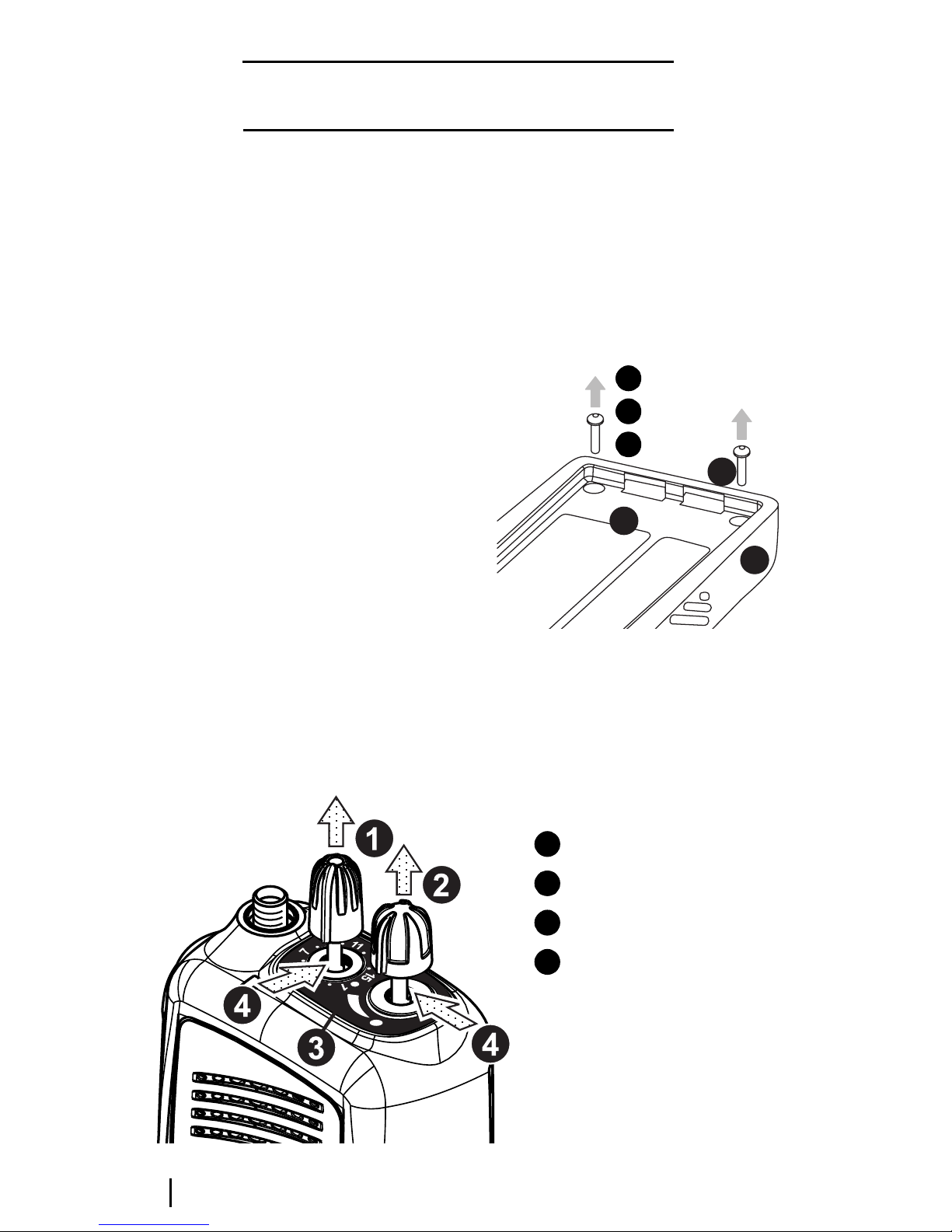
Disassembling the radio
Removing the front panel from the
chassis
Unscrew the antenna and detach the battery pack.
The channel selector and on/off/volume
control knobs need to removed before separating the front panel and the chassis.
To remove the knobs, insert a side cutter at the
base of each knob, flat side down (Figure D-2),
making sure not to damage the knob label and
the switch shaft. Squeeze lightly; the knobs
should pop off. Discard the knobs.
Some earlier Tait Orca 5000 portable radios
have the knobs glued on. If so, the knob’s
metal insert will remain on the switch shaft.
Remove the insert using a sharp scalpel blade.
Remove the two chassis screws at the base of
the radio (Figure D-1), then reattach the
battery and hold the base of the radio in one
hand. With the other hand, pull the chassis
from the front panel using the base of the
battery as leverage (Figure D-3).
At this point you can replace the following:
■ the front panel assembly;
■ the PTT keypad (PTT key and function keys);
■ the speaker;
■ the lens;
■ the keypad; and
■ the volume plate and volume keypad.
Figure D-1: Removing the chassis screws
chassis
1
front panel
2
chassis screws
3
3
1
2
Note that you should not attempt to remove
the PTT keypad before removing the front
panel from the chassis. See “Replacing the PTT
keypad” on page D-8 for more information.
Figure D-2: Removing the knobs
D - 4 Disassembling the radio June 2003 IPN: M5000-00-105
channel selector
1
on/off/volume control
2
knob label
3
insert side cutters here
4
Page 59
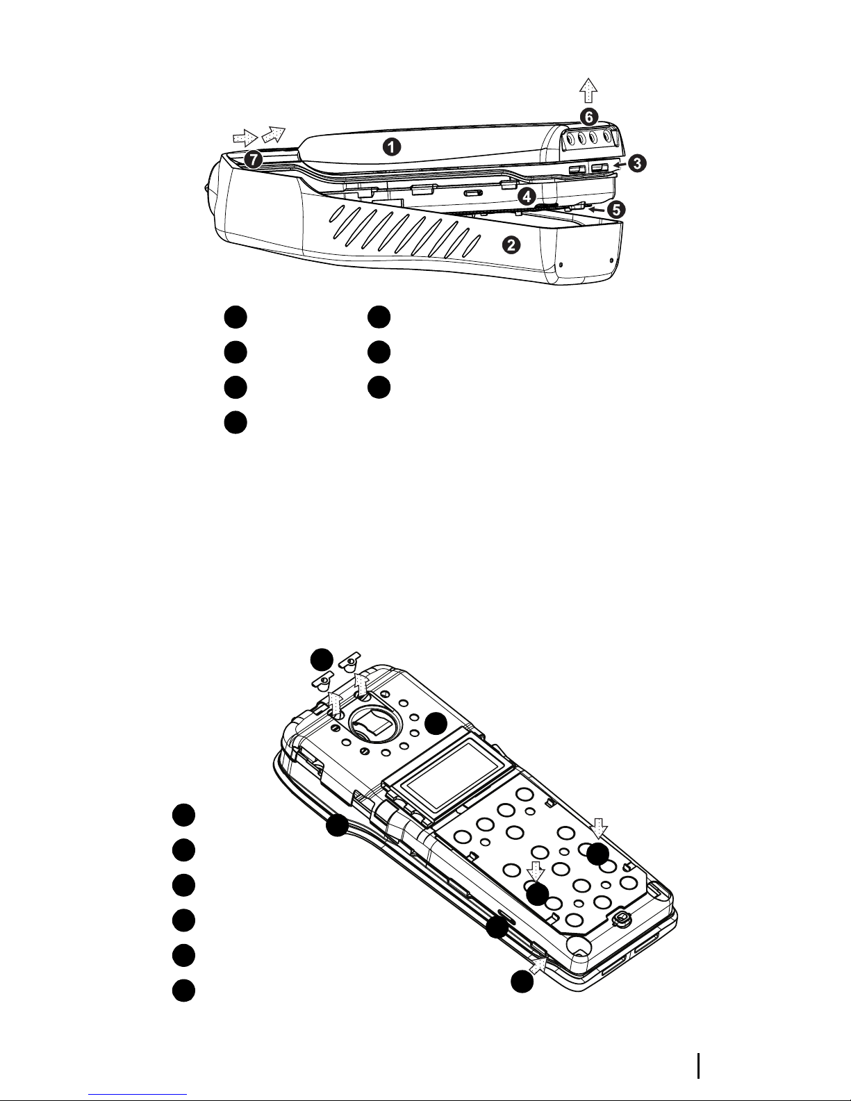
Figure D-3: Removing the front panel from the chassis, using the battery as leverage
battery pack
1
front panel
2
chassis
3
shield
4
microphone grommet protruding from the shield
5
grip battery here, gently pull away from the front panel
6
pull radio out and away from the front panel at this point
7
Removing the shield sub-assembly
from the chassis
Remove the plastic speaker pins. Place the
radio’s internal assembly on a flat surface with
the shield side facing up toward you. Press
lightly down on the shield sub-assembly above
the slot clip detail (shown in Figure D-4),
which will slightly bow the shield away from
1
the chassis.
Maintain pressure and insert a flat bladed
screwdriver (approximately 4 mm) in the gap
between the shield and the chassis. Twist the
screwdriver and the shield should rise up over
the clip.
Figure D-4: Removing the shield sub-assembly from
the chassis
remove speaker pins
1
shield
2
chassis
3
slot clip detail
4
apply pressure here
5
insert screw driver here and twist
6
June 2003 IPN: M5000-00-105 Disassembling the radio D - 5
2
3
5
5
4
6
Page 60

Repeat this on the other side. Remove the
microphone grommet by pulling upward
(Figure D-5).
You can now see the bottom surface of the
PCB. The basic layout of the PCB is shown in
Figures D-8 and D-9. Refer to these diagrams
for the placement of parts.
Note that on Orca 5015, Orca 502x, Orca 5035
and Orca 5040 radios, the user interface loom
must be detached from the main PCB before
the shield can be separated from the main PCB
and chassis.
At this point you can replace:
■ the main PCB assembly;
■ the antenna connector;
■ the channel selector switch;
■ the volume control switch;
■ the microphone;
■ the speaker contacts;
■ the battery contacts;
■ the PTT tact switch; and
At this point you can replace:
■ the LCD display (Orca 5015, Orca 502x,
Orca 5035 and Orca 5040); and
■ the shield, complete with user interface
PCB assembly and polyester dome (Orca
5015, Orca 502x, Orca 5035 and Orca
5040).
Removing the PCB from the
chassis
Remove the knob seal, which covers the antenna connector, channel selector switch and
volume control switch.
Remove the screw through the PA shield.
Remove the three nuts for the antenna connector and knobs using the supplied 8 mm long
reach socket driver, then remove the three
ribbed lock washers. Gently lift the PCB up to
the angle shown in Figure D-5, then pull it
away from the chassis.
■ the RF out assembly.
Figure D-5: Removing the PCB from the chassis
microphone grommet
1
PCB
2
chassis
3
D - 6 Disassembling the radio June 2003 IPN: M5000-00-105
Page 61

Removing the rear panel
Follow the disassembly instructions and disassemble the radio to the PCB level. Refer to
Figure D-10 for the details of the rear panel
assembly.
Insert a small flat bladed screw driver under
the auxiliary dummy rear cover and apply
pressure to push the dummy rear cover lugs
free of the holes in the rear panel. To remove
the rear panel, insert a small flat-bladed screwdriver just under the notch in the base and
twist.
Remove the rear panel seal. Note that the RF
contact pin normally remains in the rear panel
seal. Make sure that this is not lost during
disassembly.
Using a calibration pin, lift the auxiliary flexible PCB contact area from the lower lefthand
corner. Remove the flexible PCB with the seal
from the chassis; they should come out as a
unit.
You can now replace the auxiliary flexible PCB.
June 2003 IPN: M5000-00-105 Disassembling the radio D - 7
Page 62

Replacing key mechanical
and ancillary devices
This section describes the replacement of key
mechanical and ancillary devices. These
include:
■ lens (Orca 5015/2x/35/40);
■ PTT keypad;
■ speaker;
■ LCD display (Orca 5015/2x/35/40);
■ shield, complete with user interface PCB
and polyester dome;
■ antenna connector;
■ channel selector switch;
■ volume control switch;
■ microphone;
■ speaker contacts;
■ battery contacts;
■ PTT tact switch; and
Press firmly into position, then remove the
piece of clear plastic from the front of the lens.
Figure D-6: Replacing the lens
■ chassis.
Note that instructions for replacing the RF out
assembly and the auxiliary flexible PCB are
included as part of the reassembly instructions.
Refer to Figures D-8 and D-9 for the placement
of parts. Once the required devices have been
replaced, refer to the reassembly instructions
on pages D-14 to D-16.
Replacing the lens (Orca 5015/2x/
35/40)
You must disassemble the radio before gently
prising the lens away from the front panel of
the radio. Remove any adhesive remaining on
the front panel.
Peel the paper from the back of the new lens,
and place the lens in position on the front
panel.
lens
1
front panel
2
gently prise the lens away from the front panel
3
Replacing the PTT keypad
Following the disassembly instructions,
remove the front panel from the chassis.
To remove the PTT retaining plate, from the
inside of the front panel, gently push the
central latch that holds the retaining plate in
place. Discard the PTT retaining plate. Be
careful not to lose the two pins that act as
actuators for the function keys.
To install the new PTT retaining plate, insert
the bottom tab into the hole at the bottom of
the PTT recess. Bend the PTT retaining plate
very slightly so that the top tab slots easily into
D - 8 Replacing key mechanical and ancillary devices June 2003 IPN: M5000-00-105
Page 63
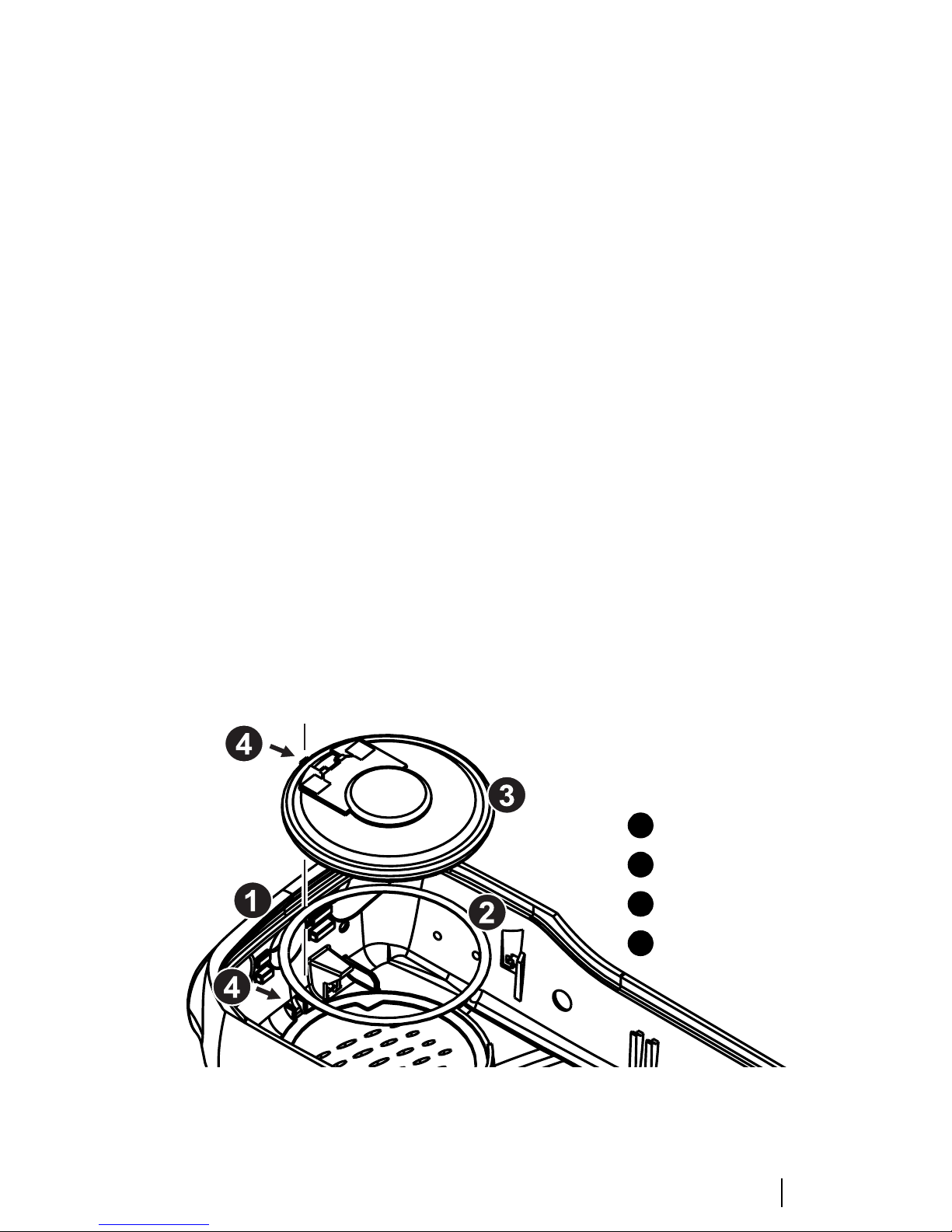
the hole at the top of the PTT recess. Be sure
not to split or otherwise damage it.
Replacing the LCD display (Orca
5015/2x/35/40)
Replacing the speaker
Following the disassembly instructions,
remove the front panel from the chassis. The
speakers sits in the inside of the front panel
(see Figure D-7).
Using a scalpel and a flat screw driver, carefully
remove the speaker from the front panel.
Clean with alcohol any remaining adhesive
from the speaker seating. Replace the adhesive
ring and secure a new speaker in place. Be sure
to align the tabs.
Following the disassembly instructions, remove
the shield from the front panel and unplug the
user interface loom from the main PCB.
Unplug the LCD display loom from the user
interface PCB, remove the LCD display from
the shield and discard the LCD display.
Position the new LCD display on the shield,
pass the LCD loom through the gap in the
shield and plug into the connector on the user
interface PCB. Push down the two connector
lugs to secure the loom.
Plug the user interface PCB loom onto the
connector on the main PCB and push down the
connector lugs to secure.
Refit the shield onto the chassis (refer to page
D-15 for detailed instructions).
Place the LCD holder over the LCD, fitting the
LCD holder locating blocks into the holes in
the shield.
Figure D-7: Mounting the speaker in the front panel
Refit the front panel to the chassis (refer to
page D-16 for detailed instructions).
front panel
1
adhesive
2
speaker
3
alignment tabs
4
June 2003 IPN: M5000-00-105 Replacing key mechanical and ancillary devices D - 9
Page 64

Figure D-8: Bottom surface of the PCB, which is visible when the shield has been removed from the chassis
1
2 3
7
5
5
4
6
antenna connector
1
channel selector switch
2
on/off/volume control switch
3
8
antenna connector pin placement
4
(5 pins)
9
10
speaker contact pin placement
5
channel selector pin placement
6
(6 pins)
on/off/volume control pin
7
placement (5 pins)
12
13
11
PTT tact switch
8
PA can
9
PA screw
10
microphone placement
11
microphone grommet placement
12
user interface loom connector
13
D - 10 Replacing key mechanical and ancillary devices June 2003 IPN: M5000-00-105
Page 65

Figure D-9: Top surface of PCB, which is visible only when the PCB has been removed from the chassis
123
4
5
7
antenna connector
1
6
channel selector switch
2
on/off/volume control switch
3
8
RF assembly placement
4
auxiliary flex socket
5
PTT tact pin placement (4 pins)
6
battery contact placement
7
battery contact seal placement
8
microphone pin placement (2 pins)
9
June 2003 IPN: M5000-00-105 Replacing key mechanical and ancillary devices D - 11
9
Page 66

Replacing the shield, user interface
PCB and polyester dome (Orca
edge of the PCB. Solder it in place using a lighttip soldering iron (e.g. Weller PTR7 tip).
5015/2x/35/40)
On Orca 5015/2x/35/40 radios the shield, user
interface PCB and polyester dome are replaced
as one complete assembly.
Following the disassembly instructions, remove
the shield from the front panel and unplug the
user interface loom from the user interface
PCB.
Remove the LCD display assembly from the
discarded shield, and fit to the replacement
shield according to the instructions on page D-
9.
Plug the user interface loom into the connector
on the new user interface PCB, and reassemble
the shield onto the chassis according to the
instructions on page D-15.
Replacing the antenna connector,
channel selector switch and volume
control switch
Following the disassembly instructions, disassemble the radio to the PCB level. Remove the
PCB from the chassis.
Replacing the battery and speaker
contacts
Following the disassembly instructions, disassemble the radio to the PCB level. Remove the
PCB from the chassis.
When replacing one of the battery or speaker
contacts, replace the other contact, even if only
one is faulty. If available, use solder paste to
replace the contacts.
Note that the contacts are heat-sensitive and
will fail if they are overheated.Low temperature solder must be used and the contacts must
not be heated above 260°C.
Remove the contact with a soldering iron and
discard. Refer to Figures D-7 and D-8 for the
placement of the battery and speaker contacts.
Solder the replacement contact in place using a
heavy-tip soldering iron (e.g. Weller 2PTCC8
tip). Hold onto the contact with a pair of pliers
and apply large amounts of solder to the PCB,
rather than to the contact, to avoid damaging
the contact.
If any of the antenna connector, channel selector switch or volume control switch need to be
replaced, remove them using a vacuumoperated solder station. Replace them according to the reassembly instructions on pages D14 to D-17.
Replacing the microphone
Following the disassembly instructions, disassemble the radio to the PCB level. Remove the
PCB from the chassis.
Use a desoldering station to remove the microphone. Discard the microphone.
When replacing the microphone, make sure it
is aligned with the marks on the PCB, since it is
polarised. Refer to Figures D-8 and D-9 for the
placement of the microphone.
The microphone should not hang over the
Replacing the tact switch
Following the disassembly instructions, disassemble the radio to the PCB level. Remove the
PCB from the chassis.
Remove the PTT tact switch using a desoldering station or solderwick. Note that there is a
lot of solder on both sides of the board, so be
sure to remove it all.
Refer to Figures D-8 and D-9 for the placement
of the PTT tact switch.
Place the new PTT on the board and solder it in
place using a heavy-tip soldering iron (e.g.
Weller 2PTCC8 tip).
D - 12 Replacing key mechanical and ancillary devices June 2003 IPN: M5000-00-105
Page 67

Replacing the chassis
Following the disassembly instructions, fully
disassemble the radio. Discard both the
chassis and main seal.
Inspect a new main seal to determine orientation and top/bottom surfaces. The tab is located at the top of the radio. Note that the seal is
not flat. Ensure that the orientation is such
that the bends follow the groove on the new
chassis.
Locate the tab in the hole at the top of the
chassis groove. Place top corners. Smooth seal
into position across the top of the chassis.
Place the seal in the groove at the bottom of the
radio and locate the corners.
Starting at the corners and moving towards
the middle, work the seal into place along both
sides of the chassis. Be careful not to stretch the
seal.
Ensure that the seal is fully inserted in the
groove all the way around the chassis. Ensure
that it is not pinched when the radio is
reassembled.
June 2003 IPN: M5000-00-105 Replacing key mechanical and ancillary devices D - 13
Page 68

Reassembling the radio
This section describes the reassembly of the
radio once the required units have been
serviced. Additional instructions for replacing
the following mechanical and ancillary devices
are also included:
■ auxiliary flexible PCB;
■ RF out assembly;
■ volume plate and volume keypad;
■ antenna connector;
■ channel selector switch; and
■ volume control switch.
Rear panel reassembly and
replacing the auxiliary flexible PCB
Follow the instructions on page D-7 to access
the auxiliary flexible PCB, and replace. Push
the flexible PCB with seal firmly into the
chassis, aligning the notch in the seal with the
locating pin on the chassis (see Figure D-10).
The rubber must sit flush with the back of the
chassis or the rear panel will not sit properly
and the battery will not fit correctly.
Fold the flexible PCB over and fit the contact
area on the chassis; it should fit snugly in place.
Replace the rear panel seal by tucking the two
tags at the top of the seal under the lip on the
chassis and folding it over the flexible PCB.
Check that the RF contact pin is positioned
correctly in the rear panel seal, and that the
seal is flush with the chassis.
Slide the rear panel on from the top of the
radio (Figure D-10). Force it into place by
pressing the top edge of the cover against the
edge of a table; it will clip home. Make sure the
gap between the cover and the chassis is as
small as possible. Refit the auxiliary dummy
cover by pushing the lugs into the holes on the
rear panel. Replace the chassis plug seal,
pushing it onto the chassis boss.
Figure D-10: Rear panel assembly
auxiliary flexible PCB
1
auxiliary flex seal
2
end of auxiliary flex connector protruding
3
through the seal
make sure the seal and auxiliary flex
4
are firmly seated in the chassis here
rear panel seal
5
chassis
6
replace rear panel
7
RF contact pin
8
chassis plug seal
9
8
5
1
7
4
9
2
3
6
D - 14 Reassembling the radio June 2003 IPN: M5000-00-105
Page 69

Fitting the PCB to the chassis and
replacing the RF out assembly
Put the battery contact seal over the battery
contacts rather than into the chassis. If you put
the seal on the chassis, the contacts will squash
the seal.
Fit the replacement RF out assembly as shown
in Figure D-11.
If you have removed the antenna connector or
either of the switches, fit them on the PCB
(refer to Figures D-8 and D-9), but do not yet
solder them in place. Align them with the holes
in the chassis, and as you lower the PCB onto
the chassis, make sure the accessory flex
protruding from the chassis fits into the socket
on the PCB. Lower the PCB onto the chassis,
making sure it is firmly seated.
socket driver set to 10in.lb (1.1Nm). Then
tighten the PA screw to 2in.lb (0.23Nm).
Using a heavy-tip soldering iron (e.g. Weller
2PTCC8 tip), solder the antenna connector
and two switches in place, if required, taking
care not to damage the surrounding components.
Replace the knob seal over the antenna
connector and the two switches (see Figure
D-12).
Fitting the shield to the chassis
Replace the microphone grommet over the
microphone.
Replace the shield from the top of the radio,
ensuring that the two pins on the chassis go
into the two holes at the top of the shield.
Fit the PA screw loosely in place. Align the
switches so they are centred, referring to
Figures D-8 and D-9 for placement.
Figure D-12 shows the reassembly of the
antenna and switches. Replace the washers,
making sure the cone faces up. The nuts for the
two switches are black.
Replace the nuts, making sure they are threaded correctly before using an 8 mm long reach
Figure D-11: Placing the RF out assembly
1
4
3
2
Replace the plastic speaker pins.
Should the main seal need replacing, place the
new seal so that the notch at the top of the
chassis (behind the channel selector switch)
matches that on the seal and the profile matches the chassis.
Run your finger around the seal to ensure that
it fits properly into the seal retaining well.
RF out assembly
1
insert here
2
antenna connector
3
auxiliary flex socket
4
June 2003 IPN: M5000-00-105 Reassembling the radio D - 15
Page 70
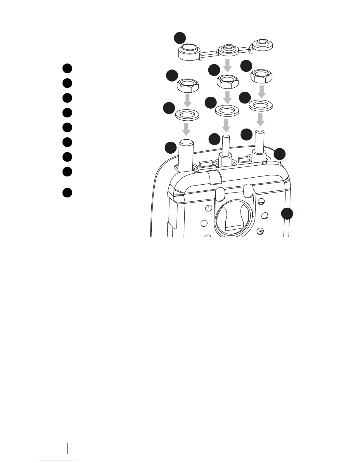
Figure D-12: Assembly of the switches
9
shield
1
chassis
2
antenna connector
3
channel selector switch
4
on/off/volume control switch
5
ribbed lock washer (M6x10x0.7 mm)
6
SMA connector nut (¼x7.9x3 mm)
7
channel/volume control nut
8
(M6x7.9x3 mm)
knob seal
9
8
8
7
6
6
6
5
4
3
2
1
Fitting the front panel to the
chassis
Place the radio into the front panel top first,
inserting the antenna connector and knob
switches through the holes. Gently ease the
radio into the front panel until the edge of the
chassis is flush with the edge of the front panel,
while making sure that the seal is not pinched;
using the battery as leverage as in radio disassembly may be helpful. Replace the two chassis
screws at the base of the radio, tightening them
to 2in.lb (0.23Nm).
Replace the two knobs on the radio with new
knobs. Press each knob on firmly. There should
be a small gap between the knob label and the
base of the knob.
D - 16 Reassembling the radio June 2003 IPN: M5000-00-105
Page 71

Spares kits
The following table shows a list of spares kits
which are currently available for servicing Tait
Orca 5000 portable radios. Spares kits are
designed to service 100 radios, and can be
ordered from your local Tait dealer.
Table D-1: Spares kits
Product code Description
TOPA-SP-401G Orca 5010/11/30 spares kit
TOPA-SP-402G Orca 5035 spares kit
TOPA-SP-403G Orca 5015/2x/40 spares kit
TOPA-SP-404 Orca 5010/11/30 re-skinning kit
TOPA-SP-405 Orca 5035 re-skinning kit
TOPA-SP-406 Orca 5020/40 re-skinning kit
TOPA-SP-407 Orca 5015/2x/35/40 U/I PCB +
shield
TOPA-SP-408 Orca 5015/21 re-skinning kit
TOPA-SP-504 Battery catch x 10
PCB Product Codes
Tait Orca 5000 main PCBs are available on an
exchange basis from Technical Support at Tait
Electronics Ltd. When ordering, use the
following naming convention
TOP-XXXXX-KS.
For example, a replacement main PCB for a
TOP-B2620-T0 is a TOP-B2620-KS.
The Tait Orca product code can be found on
the chassis type approval label, which is visible
when the battery is removed.
TOPA-SP-506 Orca 5000 series volume knobs x 10
TOPA-SP-507 Orca 5000 series channel knobs x 10
The contents of the Orca 5000 low, mid and
high tier spares kits (TOPA-SP-401G,
TOPA-SP-402G and TOPA-SP-403G) are
shown in Tables D-2, D-3 and D-4. The
contents of the Orca 5000 portable radio reskinning kits are shown in Tables D-5, D-6 and
D-7.
Information contained in the tables
Note that the ‘IPN’ column is the ten digit
‘internal part number’ which uniquely identifies any component used in a Tait product.
The numbers in the ‘Reference’ column are
Figure numbers in which the spares item is
shown, and the number in brackets refers to
the numbered legend within each figure.
June 2003 IPN: M5000-00-105 Spares kits D - 17
Page 72

Table D-2: Orca 5010/11/30 spares kit (TOPA-SP-401G)
IPN Description Quantity Reference
040-05500-08 Volume Control Switch 10 D-8 (3), D-9 (3)
219-50029-00 RF out assembly 5 D-11 (1)
220-01414 -03 Au x Fl ex Connecto r PC B 5 D -10 ( 1)
231-00010-45 Channel Selector Switch 10 D-8 (2), D-9 (2)
232-00010-42 Switch PTT (Low Profile) 5 D-8 (8), D-9 (6)
240-02156-01 Antenna SMA Connector 10 D-12 (4)
252-00010-77 Speaker 40mm 0.5W 16E FST 5 —
252-00010-56 Microphone 5 D-8 (11)
303-10053-00 Radio Chassis 5 D-4 (2), D-5 (3)
303-30072-00 Battery Catch 20 —
30 8-01015-0 0 Hous ing Ac cess ory D umm y Co ver 20 —
311-01049-xx Channel Selector Knob 20 D-2 (1)
311- 03108 -00 PTT/ Funct ion Keyp ad 10 —
316-06763-00 Knob Label 5 D-2 (3)
316-06765-02 Rear Panel 10 D-10 (7)
316- 85133-0 0 PTT/ Fu n cti on Key Re t aini ng P lat e 10 —
319-0102 6-00 Main RF Shi eld 5 D-4 (1)
345-00020-09 PA Screw M2x5mm Pan Torx 10 D-8 (10)
345-00020-11 Chassis Screw M2x8mm Pan Torx 10 D-1 (3)
352-00010-52 Channel/volume Control Nut (M6x7.9x3mm) 20 D-12 (9)
352-01053-00 Antenna SMA Connector Nut 10 D-12 (8)
353-00010-42 Ribbed Lock Washer M6x10x0.7mm 30 D-12 (7)
360-01060-00 PTT/Function Key Actuator 40 —
360-02019-00 Microphone Grommet/Seal 10 D-5 (1)
365-01673-00 Insert Front Panel Logo Label 1 —
362-01035-01 Chassis Plug Seal (green) 10 D-10 (9)
362-01106-00 Rear Panel Seal 10 D-10 (5)
362--01089-01 Aux Flex Seal 10 D-10 (2)
362-01091-01 Knob Seal 10 D-12 (10)
362-01092-02 Main Seal 20 —
369-01039-00 Adhesive Ring 40mm (speaker) 5 D-7 (2)
304-07044-00 Speaker pin frame 20 —
316-85027-00 Pin External RF out assembly 10 —
356-01070-00 Speaker Contact Probe Spring 10 —
339-00010-53 Plastic bag, 150x250mm 11 —
399-00010-69 Plastic bag, 75x100mm Mini grip 23 —
311-01153-00 Package carton, T2000 SII, unprinted 1 —
365-01663-00 Warning Labels for Green D-Clips 1 —
OPP401 Front Panel Assembly. This comprises the following parts: 5 —
252-00010-77 Speaker 40mm 0.5W 16E FST 1 —
307-01022-00 Speaker cloth 1 —
316-06760-xx Front Panel 1 —
316-06763-00 Knob Label 1 D-2 (3)
354-01044-00 Bush M2 Threaded Brass 2 —
369-01039-00 Adhesive Ring 40mm (speaker) 1 D-7 (2)
316-85133-00 PTT/Function key retaining plate 1 —
311-03108-00 PTT/Function keypad 1 —
360-01060-00 PTT/Function key actuator 2 —
399-00010-91 Plastic bag, 96x225mm 1 —
D - 18 Spares kits June 2003 IPN: M5000-00-105
Page 73

Table D-3: Orca 5035 spares kit (TOPA-SP-402G)
IPN Description Quantity Reference
040-05500-08 Volume Control Switch 10 D-8 (3), D-9 (3)
219-50029-xx RF out assembly 5 D-11 (1)
220-01414-03 Aux Flex Connector PCB 5 D-10 (1)
231-00010-45 Channel Selector Switch 10 D-8 (2), D-9 (2)
232-00010-42 Switch PTT (Low Profile) 5 D-8 (8), D-9 (6)
240-02156-01 Antenna SMA Connector 10 D-12 (4)
252-00010-77 Speaker 40mm 0.5W 16E FST 5 —
252-00010-56 Microphone 5 D-8 (11)
303-10053-00 Radio Chassis 5 D-4 (2), D-5 (3)
303-30072-00 Battery Catch 20 —
30 8-01015 -00 H ous ing Acc ess ory D umm y C ove r 20 —
311-01049-00 Channel Selector Knob 20 D-2 (1)
311-01050-00 Volume Knob 20 D-2 (2)
311-03108-00 PTT/Function Keypad 20 —
311-03110-00 Keypad 5 —
312-01087-00 Lens Coa ted 2 D -8( 1)
303-23098-00 Protective Lens Cover 5 —
316-06763-00 Knob Label 5 D-2 (3)
316-06765-02 Rear Panel 5 D-10 (7)
316- 85133- 00 P TT/Fun cti on Key R eta inin g P lat e 10 —
345-00020-09 Screw M2x5mm Pan Torx 10 D-8 (10)
345-00020-11 Chassis Screw M2x8mm Pan Torx 10 D-1 (3)
352-00010-52 Channel/volume Control Nut (M6x7.9x3mm) 20 D-12 (9)
352-01053-00 Antenna SMA Connector Nut 10 D-12 (8)
353-00010-42 Ribbed Lock Washer M6x10x0.7mm 30 D-12 (7)
360-01060-00 PTT/Function Key Actuator 40 —
360-02019-00 Microphone Grommet/Seal 10 D-5 (1)
362-01035-01 Chassis Plug Seal (green) 10 D-10 (9)
362-01087-00 Battery Contact Seal 10 D-9 (8)
36 2-0110 6-0 0 Rea r P ane l Se al 10 D-10 (5)
362--01089-01 Aux Flex Seal 10 D-10 (2)
36 2-010 91-01 Knob Sea l 10 D- 12 (10)
362-01092-02 Main Seal 20 —
369-01039-00 Adhesive Ring 40mm (speaker) 5 D-7 (2)
316-85027-00 Pin External RF out assembly 5 —
304-07044-00 Speaker pin frame 20 —
356-01070-00 Speaker Contact Probe Spring 10 —
339-00010-53 Plastic bag, 150x250mm 16 —
399-00010-69 Plastic bag, 75x100mm Mini grip 25 —
311-01153- 00 Pack age ca rton, T2 000 SI I, u npr inted 1 —
365-01663-00 Warning Labels for Green D-Clips 1 —
TOPA-SP-407 User Interface Kit, 5020/21/35/40, with PCB & Shield 5 —
OPP501 Front Panel Assembly. This comprises the following parts: 5 —
252-00010-77 Speaker 40mm 0.5W 16E FST 1 —
307-01022-00 Speaker cloth 1 —
316- 06761 -00 Fro nt Pan el 1 —
316-06763-00 Knob Label 1 D-2 (3)
354-01044-00 Bush M2 Threaded Brass 2 —
369-01039-00 Adhesive Ring 40mm (speaker) 1 D-7 (2)
360-01060-00 Preselect Actuator 2 —
311-03108-00 PTT/Function keypad 1 —
316-85133-00 PTT/Function key retaining plate 1 —
312-01087-00 Lens, Coated 1 D-8(1)
303-23098-00 Protective Lens Cover 1 —
399-00010-91 Plastic bag, 96x225mm 1 —
June 2003 IPN: M5000-00-105 Spares kits D - 19
Page 74

Table D-4: Orca 5015/2x/40 spares kit (TOPA-SP-403G)
IPN Description Quantity Reference
008-36671-80 LCD Display 1 —
040-05500-08 Volume Control Switch 10 D-8 (3), D-9 (3)
219-50029-00 RF out assembly 5 D-11 (1)
220-01414 -03 Au x Fl ex Connecto r PC B 5 D -10 ( 1)
231-00010-45 Channel Selector Switch 10 D-8 (2), D-9 (2)
232-00010-41 Switch PTT (Low Profile) 5 D-8 (8), D-9 (6)
240-02156-01 Antenna SMA Connector 10 D-12 (4)
252-00010-77 Speaker 40mm 0.5W 16E FST 5 —
252-00010-56 Microphone 5 D-8 (11)
303-10053-00 Radio Chassis 5 D-4 (2), D-5 (3)
303-30072-00 Battery Catch 20 —
30 8-01015-0 0 Hous ing Ac cess ory D umm y Co ver 20 —
311-01049-00 Channel Selector Knob 20 D-2 (1)
311- 01050 -01 Volume Kn ob 2 0 D-2 (2 )
311-03108-01 PTT/Function Keypad 20 —
311-03109-00 Keypad TOP5020/5040 5 —
311-03113-00 Keypad TOP5021 5 —
312-01087-00 Lens Coated 2 D-6 (1)
303-23098-00 Protective Lens Cover 5 —
316-06763-00 Knob Label 5 D-2 (3)
316-06765-02 Rear Panel 5 D-10 (7)
316- 85133-0 0 PTT/ Fu n cti on Ret ain ing Pla te 10 —
345-00020-09 PA Screw M2x5mm Pan Torx 10 D-8 (10)
345-00020-11 Chassis Screw M2x8mm Pan Torx 10 D-1 (3)
349-00030-00 Speaker Screw 1.8x5mm Torx 10 D-7 (3)
352-00010-52 Channel/volume Control Nut (M6x7.9x3mm) 20 D-12 (9)
352-01053-00 Antenna SMA Connector Nut 10 D-12 (8)
353-00010-42 Ribbed Lock Washer M6x10x0.7mm 30 D-12 (7)
356-01070-00 Speaker Contact Probe Spring 10 —
360-01060-00 PTT/Function Key Actuator 40 —
360-02019-00 Microphone Grommet/Seal 10 D-5 (1)
362-01035-01 Chassis Plug Seal (green) 10 D-10 (9)
362-01087-00 Battery Contact Seal 10 D-9 (8)
362-01106-00 Rear Panel Seal 10 D-10 (5)
362--01089-01 Aux Flex Seal 10 D-10 (2)
362-01091-01 Knob Seal 10 D-12 (10)
362-01092-02 Main Seal 20 —
369-01039-00 Adhesive Ring 40mm (speaker) 5 D-7 (2)
304-07044-00 Speaker pin frame 20 —
316-85027-00 Pin External RF out assembly 20 —
311-01153-00 Package carton, T2000 SII, unprinted 1 —
339-00010-53 Plastic bag, 150x250mm 13 —
399-00010-69 Plastic bag, 75x100mm Mini grip 23 —
365-01663-00 Warning Labels for Green D-Clips 1 —
TOPA-SP-407 User Interface Kit, 5020/21/35/40, with PCB & Shield 5 —
OPP601 Front Panel Assembly. This comprises the following parts: 5 —
252-00010-77 Speaker 40mm 0.5W 16E FST 1 —
307-01022-00 Speaker cloth 1 —
316-06762-00 Front Panel 1 —
316-06763-00 Knob Label 1 D-2 (3)
369-01039-00 Adhesive Ring 40mm (speaker) 1 D-7 (2)
360-01060-00 Preselect Actuator 2 —
311-03108-00 PTT/Function keypad 1 —
316-85133-00 PTT/Function key retaining plate 1 —
312-01087-00 L ens , C oate d 1 D-8( 1)
303-23098-00 Protective Lens Cover 1 —
399-00010-91 Plastic bag, 96x225mm 1 —
D - 20 Spares kits June 2003 IPN: M5000-00-105
Page 75

Table D-5: Orca 5010/11/30 re-skinning kit (TOPA-SP-404)
IPN Description Quantity
311-01049-01 Channel Knob 1
311- 01050 -01 Vol ume Kno b 1
316-06765-00 Rear Panel 1
345-00020-11 Screw M2x8mm SS Pan Torx Patch 2
36 2-0110 6-0 0 Rea r C ove r S eal 1
36 2-010 91-01 Knob Sea l 1
362-01092-02 Main Seal 1
OPP401 PHA Front Panel Assembly 1
399-00010-69 Plastic Bag 75x100mm Mini Grip 1
399-00010-53 Plastic Bag 150x250mm 1
410-01064-01 Packaging Header Card New Logo 1
316-0 676 5- 01 Rea r Pa nel 1
Table D-6: Orca 5035 Re-skinning kit (TOPA-SP-405)
IPN Description Quantity
311-01049-01 Channel Knob 1
311- 01050 -01 Vol ume Kno b 1
311-03110-00 Keypad 1
316-06765-00 Rear Panel 1
345-00020-11 Screw M2x8mm SS Pan Torx Patch 2
36 2-0110 6-0 0 Rea r C ove r S eal 1
36 2-010 91-01 Knob Sea l 1
362-01092-02 Main Seal 1
OPP501 PHA Front Panel Assembly 1
399-00010-69 Plastic Bag 75x100mm Mini Grip 1
399-00010-53 Plastic Bag 150x250mm 1
410-01064-01 Packaging Header Card New Logo 1
316-0 676 5- 01 Rea r Pa nel 1
Table D-7: Orca 5020/40 Re-skinning kit (TOPA-SP-406)
IPN Description Quantity
311-01049-01 Channel Knob 1
311- 01050 -01 Vol ume Kno b 1
311-03109-00 Keypad 1
316-06765-00 Rear Panel 1
345-00020-11 Screw M2x8mm SS Pan Torx Patch 2
36 2-0110 6-0 0 Rea r C ove r S eal 1
36 2-010 91-01 Knob Sea l 1
362-01092-02 Main Seal 1
OPP601 PHA Front Panel Assembly 1
399-00010-69 Plastic Bag 75x100mm Mini Grip 1
399-00010-53 Plastic Bag 150x250mm 1
410-01064-01 Packaging Header Card New Logo 1
316-0 676 5- 01 Rea r Pa nel 1
June 2003 IPN: M5000-00-105 Spares kits D - 21
Page 76

Table D-8: Orca 5015/2x/35/40 User Interface PCB and Shield (TOPA-SP-407)
IPN Description Quantity
OPF200-B UI PCB SMT Subassembly 1
311-04005-00 Ins Poly Dome for 5015/2x/40 1
319-0102 6-00 Main Shi eld RF 1
399-00010-86 Static Shielding Bag 127x203mm 1
008-36671-80 LCD Display 12x2 Lines Flex 1
304-07043-00 LCD Frame Holder 1
220-01501-00 PCB Flexi User Interface 1
369-01044-00 Conductive Adhesive/Mylar
365-00011-38 Yellow Label Static Warning
Table D-9: Orca 5015/21 Re-skinning kit (TOPA-SP-408)
IPN Description Quantity
311- 01049 -01 Chan nel Kn ob 1
311- 01050 -01 Volume Kn ob 1
311-03113-00 Keypad 1
316-06765-00 Rear Panel 1
345-00020-11 Screw M2x8mm SS Pan Torx Patch 2
362-01106-00 Rear Cover Seal 1
362-01091-01 Knob Seal 1
362-01092-02 Main Seal 1
OPP601 PHA Front Panel Assembly 1
399-00010-69 Plastic Bag 75x100mm Mini Grip 1
399-00010-53 Plastic Bag 150x250mm 1
410-01064-01 Packaging Header Card New Logo 1
316- 0676 5-01 Rea r Pa nel 1
D - 22 Spares kits June 2003 IPN: M5000-00-105
Page 77

E
PART
Battery packs and chargers
This part provides information on the battery packs and chargers
available for Tait Orca 5000 portable radios.
The battery packs are not serviceable, and repair of chargers is
limited to replacement of the spring contacts, the discharge tact
switch and the DC jack.
Contents
Battery packs
Battery packs ..................................................................................................
Battery packs Battery packs
Battery shift life ......................................................................................................E-3
Disposing of used nickel-cadmium batteries ..........................................................E-4
Battery chargers
Battery chargers .............................................................................................
Battery chargers Battery chargers
Desktop fast charger
Desktop fast charger ......................................................................................
Desktop fast charger Desktop fast charger
..................................................................................................E-3
....................................................................................................................................................................................................
.............................................................................................E-5
..........................................................................................................................................................................................
......................................................................................E-6
............................................................................................................................................................................
E-3
E-3E-3
E-5
E-5E-5
E-6
E-6E-6
Fast charger operation ............................................................................................E-6
Using the fast charger ............................................................................................. E-9
Repairing the fast charger ....................................................................................E-10
Desktop trickle charger
Desktop trickle charger ................................................................................
Desktop trickle charger Desktop trickle charger
Trickle charger operation .....................................................................................E-12
Using the trickle charger ......................................................................................E-13
Repairing the trickle charger ................................................................................E-13
Troubleshooting ...................................................................................................E-14
Multi-charger
Multi-charger ...............................................................................................
Multi-charger Multi-charger
Multi-charger operation .......................................................................................E-15
Repairing the multi-charger .................................................................................E-15
Fuse replacement .................................................................................................E-16
...............................................................................................E-15
..............................................................................................................................................................................................
................................................................................E-12
................................................................................................................................................................
E-12
E-12E-12
E-15
E-15E-15
Page 78

E - 2 June 2003 IPN: M5000-00-105
Page 79

Battery packs
Six battery packs are available for Tait Orca
5000 portable radios. These battery packs are
not serviceable, but their construction and
expected life are described below.
The battery packs available are:
■ TOPB100 NiCD battery pack;
■ TOPB600 NiCD battery pack (slim, no belt
clip);
■ TOPB200 NiCD battery pack;
■ TOPB400 NiMH battery pack;
■ TOPB700 NiMH battery pack (slim, no belt
clip); and
■ TOPB500 NiMH battery pack.
The battery casing is constructed using a
rugged resin material, and includes two pieces
that are ultrasonically welded together.
Battery shift life
Battery shift life is outlined in Table E-1.
Battery shift life for other models and circumstances can be calculated from the typical
drain rates on page E-4.
For intrinsically safe batteries, see page A-11.
Preserving battery shift life
to preserve the shift life of the battery:
■ Charge or change the battery as soon as
the radio gives the ‘Low Battery’ warning.
■ Short condition the battery weekly.
■ Long condition the battery only for the
following reasons: on first use of new
battery, if performance is poor, and after
more than two weeks of storage.
■ Avoid leaving charged batteries in the
charger for more than a day.
■ Clean electrical contacts of the battery
using a fibre glass pencil, or the graphite
tip of a type 4H (#4) or harder pencil.
■ Always store the battery detached from
the radio when storing for more than a few
days.
■ Turn the radio off when it is unattended
for long periods.
■ Use only a Tait-recommended charger.
■ Maintain an ambient temperature of
between 5°C and 40°C during recharging.
Optimum battery performance will be
obtained between 15°C and 25°C.
■ Do not allow the battery pack contacts to
become short-circuited.
It is important that you follow the steps below
Ta ble E- 1 : Typ ical b atter y shif t life (in hou rs) b ased on a 5:5:9 0 duty cycle for a ne w cond ition ed bat tery p ack*.
Battery type
TOPB100/600 NiCD 8.5 7 6.5
TOPB400/700 NiMH 10.5 8.5 8
TOPB200 NiCD 11.5 9 8.5
TOPB500 NiMH 15 12 11
* Users should aim to have one hour spare capacity at the end of their shift to allow for battery ageing.
June 2003 IPN: M5000-00-105 Battery packs E - 3
Conventional -
Medium Economy
Radio type
Conventional -
No Economy
Tru nke d
Page 80

Extending battery shift life
Battery shift life can be extended by activating
economy mode (conventional radios) or by
using dynamic power control (trunked
radios).
During economy mode, the radio cycles
between the normal receive state and a standby state, in which some of the radio’s circuitry
is switched off or placed on standby mode.
Dynamic power control optimises the radio’s
power use by reducing the transmit power in
high signal strength areas.
Typical drain rates for a conventional UHF
radio are:
■ 1.5 A at high power transmit;
■ 300 mA in receive at rated audio;
■ 80 mA on standby (no audio);
■ 55 mA with low economy cycling enabled;
■ 45 mA with medium economy cycling
enabled; and
■ 40 mA with high economy cycling
enabled.
Economy cycling in conventional radios is
programmed in the Power Save Features
screen of the Tait Orca Portable Conventional
Programming Application (TOPCPA). Dynamic
power control in trunked radios is enabled in
the User Selectable Parameters screen of
the Tait Orca Portable Trunked Programming
Application (TOPTPA).
Disposing of used nickel-cadmium
batteries
NiCd batteries contain a small amount of the
metal cadmium, which can produce potentially toxic waste if not disposed of properly.
Contact your Tait dealer for recycling details.
E - 4 Battery packs June 2003 IPN: M5000-00-105
Page 81

Battery chargers
Note:
Note: In order to charge TOPB700 NiMH
Note:Note:
batteries, the charger must have firmware
version 2.07 or greater. TOPB500 NiMH
batteries can be charged on chargers with
firmware version 2.05 or greater.
The trickle charger should not be used for
NiMH battery packs as they can take up to 24
hours to charge fully and the overall lifetime of
the battery may be reduced. NiMH battery
packs should be charged using a fast charger.
Three battery chargers are available for Tait
Orca portable radios:
■ desktop fast charger;
■ desktop trickle charger; and
■ six-way multi-charger.
The fast charger charges, conditions and
analyses the battery. The trickle charger only
charges the battery, and does not have a conditioning button but is otherwise identical in
appearance to the fast charger. The multicharger is made up of six fast chargers, and
For details on charging intrinsically safe
batteries, see page A-11.
Repair of chargers is limited to replacement of
the spring contacts, the discharge tact switch
and the DC jack.
The repair information provided for the fast
charger also applies to repair of the trickle
charger and multi-charger.
A spares kit is available for Tait Orca chargers
(TOPA-SP-202). The contents of the spares kit
is shown in Table E-2, and the assembly of
these parts is shown in Figure E-3.
charging instructions for the fast charger also
apply to the multi-charger.
Table E-2: Contents of the Tait Orca chargers spares kit (TOPA-SP-202)
IPN Description Quantity For charger
240-02020-07 Skt DC jack 10 All
232-00010-28 Tact switch 10 Desktop fast charger
Multi-charger
302-40054-01 Conditioning button 10 Desktop fast charger
Multi-charger
262-00001-00 Charger light pipe 10 Desktop fast charger
Multi-charger
312-0106 9-02 Ch arger top 10 All
312-01070-01 Charger base 10 All
365-01549-01 Charger logo label 10 All
365-01598-01
36 5-016 01-00
365-01597-00
36 5-016 01-02
369-00010-11 Rubber charger foot 40 All
360-01059-00 Trickle charger blanking label 10 Desktop trickle charger
356-01079-00 Spring probe charger bias-ball 40 All
Charger labels 10 Desktop fast charger
Multi-charger
Charger labels 5 Desktop trickle charger
June 2003 IPN: M5000-00-105 Battery chargers E - 5
Page 82

Desktop fast charger
The Tait Orca desktop fast charger (Figure E-1)
is an intelligent charger that can charge, condition and analyse both NiCd and NiMH batteries of varying capacities.
Fast charger operation
A circuit diagram of the fast charger is shown
in Figure E-2. The fast charger operates using
constant current charging and multiple criteria for end-of-charge detection. When a
battery is inserted, the charger detects the type
of battery, checks to see if it is working correctly, and then charges the battery.
If the conditioning button is pressed after
inserting the battery, the charger will
discharge the battery before charging. If the
conditioning button is held down while the
battery is being inserted, the charger will enter
a long condition cycle that will charge and
discharge the battery a number of times and,
on the last cycle, check its capacity before
recharging.
Multiple protection methods are employed to
ensure safe operation.
Figure E-1: Tait Orca fast charger
LED
Conditioning
button
sor, D1, in conjunction with PolySwitch™ PS1.
Under reverse polarity conditions, D1
conducts, drawing the available short circuit
current until PS1 trips. D1 also protects
against any voltage spikes that may come
through the AC to DC adaptor. The unit is
designed for 10.5 - 14 V operation.
The +5V supply is produced by the regulator,
IC1. A feature of this regulator is that it
provides a RESET output to the microprocessor. This RESET output is used to delay startup
of the microprocessor until the power supply
has stabilised after turn-on. It also puts the
microprocessor into reset if the input voltage
falls too low. D2 sets this low voltage threshold
to approximately 9.2 V.
The intelligence of the fast charger is provided
by the microprocessor, IC2, which interfaces
with the current source, the discharge circuit
and the expanded battery voltage interface. The
user can interact with the fast charger by pressing the conditioning button, SW1, and can
observe the operational state on the tri-colour
LED, D5.
The current source is based on a groundsensing linear topology. R1 and R2 are the
current sense resistors. The power device is a
P-channel MOSFET, Q4, which is controlled
by an operational amplifier, IC3:A. The
feedback path that controls the op amp, and
hence the current, is through transistor Q5
and its resistor network. The grounding on
R23 includes the ground sense resistors in the
feedback path. The nominal output current is
800 mA.
r
Hardware operation
Power to the unit is provided from a 12 volt,
1 amp (nominal) wall-mounted AC to DC
adaptor, through SK1. Reverse polarity protection is provided by the 22 V transient suppres-
E - 6 Desktop fast charger June 2003 IPN: M5000-00-105
Page 83

+5V
+5V
+5V
R46
100K%05
R56
47K
27K 0.5%
G3 -
-
G3 O/P
CAP
3.9MM BASE DIA
C26
R50
R49
G3 +
+
IC3
LM324D
Q6
STP16NE06
G
R39
1K0
G1 O/P
IC3
LM324D
R37
100K%05
+BATT
L1
S
R43
1K0
-
G1 -
10K 0.5%
+BATT
3.9MM BASE DIA
BLM41P800
TAN T
C54
4U7
C201
1N0
R40
R38
+5V
G2 O/P
+
-
IC3
LM324D
G2 +
G2 -
Q4
MTP2955
SGD
R17
1K0
G4 O/P
+
-
IC3
12V
G4 +
R16
Q3
BC847W
C16
1K0
C15
R15
10K 0.5%
LM324D
G4 -
18P
100N
+5V
D4
R14
47K
R19
220K
R18
27K 0.5%
VCC
R21
R20
V+
IC3
+V
1K0
100K%05
R22
LM324D
R23
10K 0.5%
C17
100N
10K 0.5%
GND
Q5
V-
R26
R25
BCW70
10K 0.5%
47K
R24
47K
HS1
R35
TO-220 HEATSINK
D
G1 +
100K%05
+
R36
R55
+5V
R411ER42
10K 0.5%
1M0
TEMP
3.9MM BASE DIA
L2
BLM11B601SL3BLM11B601S
C25
100N
10K 0.5%
1E
R45
1N0
10K 0.5%
100K%05
R48
100K%05
C20
100N
10K 0.5%
R47
C21
GND
100N
3.9MM BASE DIA
Q2
VCC
21
VIN
SK1
DC JACK 2.5MM
1APS1
+5V
BC847W
ANODE GR
VCC
C4
1N0
TAN TC34U7
R3
47K
6
7
8
SO
VOUT
VS1CT
D2
4V7
D1
22V
R2
1E
R1
1E
IC1
3
L4949
VZ
VIN
D200
I/OPAD
+
RESET
4
C200
1N4001
GND
SI
1N0
C2
C10
C1
5
2
100N
100N
1N0
I/OPAD
-
+5V
C11
100N
-RESET
+V
+V
R5
1K0
C5
100N
-IRQ
IRQ
RESET
PA7
PA6
PA7
PA6
PC7/VRH
PC6/AN0
PC7/VRH
PC6/AN0
Q1
BC847W
PA5
PA4
PA5
PA4
PC5/AN1
PC4/AN2
PC5/AN1
PC4/AN2
+5V
SW1
PA3
PA2
PA3
PA2
IC2
PC3/AN3
PC2
PC2
PC3/AN3
RL-A
TAC T
PA1
PA0
PA1
PA0
MICRO
68HC05P6
PC1
PC0
PC1
PC0
D5
ANODE RE D5
DUAL LED
CATHODE
DUAL LED
RED GREEN
CATHODE
PB5/SDO
PB6/SDI
PB5/SDO
TCMP
TCMP
PD7/TCAP
RL-K
R8
C6
R7
R6
PB7/SCK
PB6/SDI
PB7/SCK
PD7/TCAP
PD5
PD5
R33
R32
47K
1N0
47K
47K
GND
OSC1
OSC2
330
470
GND
OSC1
OSC2
C8
33P
R9
4M
1M0
XTAL
C7
33P
Figure E-2: Circuit diagram of the Tait Orca desktop fast charger
June 2003 IPN: M5000-00-105 Desktop fast charger E - 7
Page 84

The discharge circuit is based around a
constant current sink. This uses an N-channel
MOSFET, Q6, controlled by an operational
amplifier, IC3:B. R41 and R42 are the current
sense resistors that allow the op amp to set the
current. The nominal discharge current is
400 mA.
The microprocessor needs to be able to
monitor the battery voltage. A coarse voltage is
provided by the voltage divider R48, R49 and
R50. This voltage divider brings the range of
battery voltage into the same range as the
microprocessor A/D input (0-5 V). This
enables the microprocessor to monitor the
general battery voltage. An expanded battery
voltage interface is based around operational
amplifier IC3:C. It expands a small window of
battery voltage over the range of the microprocessor A/D input. This enables the microprocessor to detect small changes in battery
voltage and accurately pick when the battery
voltage drops below peak.
The interface to the battery is through four
contacts, positive (+BATT), temperature
(TEMP), capacity (CAP) and ground (GND).
The positive and ground contacts are the main
connections for charging. In the battery pack,
the temperature contact is connected to
ground via a thermistor. This allows the charger to monitor the temperature of the battery
and if the battery temperature is outside the
range +5°C to +40°C, the charger will not
charge the battery. The charger also uses the
temperature line for detecting the presence of
a battery; for example, detecting whether the
battery has been inserted or removed from the
charger. In the battery pack, the capacity
contact is connected to ground via a resistor. If
there is a capacitor in parallel with the capacity
resistor, then the resulting time constant
indicates to the charger that the battery pack is
NiMH. Consequently, battery packs that do
not have a capacitor in parallel with the capacity resistor are considered to be NiCd.
Software operation
The charging sequence is as follows.
■ Battery discharge (optional);
■ Battery flat test;
■ Battery type detection;
■ Battery open circuit test;
■ Battery short circuit test;
■ Battery temperature test;
■ Rapid charge, with multiple end-of-charge
detection methods;
■ Rest;
■ Trickle charge (optional);
■ Standby charge;
■ Maintenance charge.
If during trickle or standby charge the battery
voltage falls to the discharged battery threshold, the charger restarts the charge cycle as if
the battery has just been inserted.
E - 8 Desktop fast charger June 2003 IPN: M5000-00-105
Page 85

Using the fast charger
recharging (5°C to 40°C).
Fast charger indicators are described in Table
E-3.
Table E-3: Fast charger indicators
Indicator Meaning
steady red battery charging
steady green battery charged
steady amber charge suspended until battery tem-
perature is within correct range
flashing red battery not seated properly in the
charger, contacts dirty or battery
faulty
flashing green battery trickle charging
flashing amber battery being long or short condi-
tioned, or if flashing amber straight
away, it may indicate a fault such as
dirty contacts
Charging the battery using the fast
charger
Charging using the fast charger involves three
stages.
■ The fast charge stage quickly brings the
battery up to near its full capacity. The
charger LED will glow red.
■ The trickle stage slowly tops up the battery
until it is at its full capacity, which is
typically 1½ hours. The charger LED will
flash green.
Approximate charge times are:
■ up to 1½ hours for TOPB100 and
TOPB600;
■ up to 2 hours for TOPB200, TOPB400 and
TOPB700; and
■ up to 2½ hours for TOPB500.
Once the battery has reached approximately
90% capacity, the indicator will flash green. At
this point, it is recommended the battery be
left in the charger for a further 1 to 2 hours, to
ensure maximum battery charge. Once the
battery is fully charged, the indicator will glow
green.Avoid leaving charged batteries in the
charger for more than a day.
Conditioning the battery with the fast
charger
Two conditioning functions are available on
the fast charger, a short conditioning cycle and
a long conditioning cycle. The short cycle
discharges the battery then charges it. Regularly recharging a battery that has not been
completely discharged will eventually affect its
ability to hold a full charge.
For best performance, the battery should be
conditioned weekly using the fast charger.
Conditioning the battery takes about four to
eight hours, depending on how much use it has
had.
■ The standby charge stage keeps the
battery at its full capacity, as long as the
radio is turned off. The charger LED will
glow green.
The battery can be charged separately or
attached to the radio. The radio must be
turned off to ensure a full charge.
Turn off the radio and insert the battery/radio
into the charger. If the indicator does not glow
red, make sure the battery/radio is seated
properly and the charger is plugged in correctly. If the battery is too hot or too cold, the
indicator will remain amber until the battery
temperature is within the safe range for
June 2003 IPN: M5000-00-105 Desktop fast charger E - 9
Note
Note: Do not use the short conditioning cycle
NoteNote
on a new battery without first fully charging it
using a long conditioning cycle.
The long conditioning cycle is necessary:
■ before the battery is used for the first time;
■ if the battery performance has deteriorat-
ed; or
■ after the battery has been stored for longer
than two weeks.
Page 86

To short condition the battery
Turn off the radio and insert the battery/radio
into the fast charger. When the charger LED
glows red, press the conditioning button until
the indicator flashes amber. Release the conditioning button. The LED will flash amber while
the battery is being discharged. Once the
battery is discharged, it will charge normally.
The battery is ready to be used again when the
charger LED glows green.
To long condition the battery
Long conditioning the battery with the fast
charger will put the battery through a number
of conditioning cycles and will check the
battery’s capacity on the last cycle.
The long condition cycle will take approximately 24 hours.
Once charged, the charger’s indicator will glow
green if the battery is in good condition. The
indicator will flash red if the battery is well
below optimum capacity; consult your Tait
dealer.
Repairing the fast charger
The assembly of the fast charger is shown in
Figure E-3.
Depress the release tab in the base of the charger using the end of a flat-bladed screwdriver.
Holding the lever in, gently pull the body away
from the base. Lift out the PCB.
To long condition the battery, turn off the
radio. Press and hold the conditioning button
while inserting the battery/radio. Continue
holding the conditioning button until the
indicator flashes amber. When the indicator
flashes amber, release the conditioning
button.
1
2
3
6
8
4
Replace the battery contacts, the tact switch
and the DC jack, if necessary.
Figure E-3: Assembly of the desktop fast charger
charger base
1
access to the release tab
2
PCB
3
DC jack
4
charger top
5
conditioning button
6
7
9
E - 10 Desktop fast charger June 2003 IPN: M5000-00-105
fit conditioning button here
7
light pipe
8
fit light pipe here
9
5
Page 87

Replacing the spring contacts
t
c
Reassembling the charger
Remove the faulty contacts with a soldering
iron and discard.
If the replacement spring contacts have a
larger diameter and will not fit through the
PCB, the holes should be drilled out to 2.2mm.
When placing the replacement contact, it must
not be bent or otherwise damaged. Solder the
replacement contact in place using a heavy-tip
soldering iron (e.g. Weller 2PTCC8 tip). Hold
onto the contact with a pair of pliers and apply
solder to the PCB, rather than to the contact, to
avoid contact damage.
Figure E-4: The fast charger PCB
Capacity and
emperature
ontacts
Refer to Figure E-3.
Hold the body of the charger upside down and
insert the conditioning button and the light
pipe; both parts self-orient. Place the PCB so it
rests on the location pins. Attach the base at
the front edge, and clip it down at the back.
Table E-4: Charger Spares and Upgrade Kits:
Product code Description
TOPA-SP-202 Charger Spares Kit
TOPA-SP-203 Charger Upgrade Kit
TOPA-SP-205 Charger Software Upgrade Kit
–ve and +ve
contacts
Replacing the discharge tact switch
Remove the tact switch using a desoldering
station or solderwick. Place the new part on the
board and solder it in place using a medium-tip
soldering iron (e.g. Weller PTA7 tip).
Replacing the DC jack
Remove the DC jack using a desoldering station
or solderwick. There is a lot of solder on both
sides of the board, so be sure to remove it all.
Place the new part on the board and solder it in
place using a heavy-tip soldering iron (e.g.
Weller 2PTCC8 tip).
June 2003 IPN: M5000-00-105 Desktop fast charger E - 11
Page 88

Desktop trickle charger
The Tait Orca desktop trickle charger can
charge a 1100 mAh or 1500 mAh NiCd battery
overnight. It is designed to provide approximately 1450 mAh of charge in a 16 hour
period. Thus both 1100 mAh or 1500 mAh
NiCd batteries can be charged. Simple protection of the radio is provided in the form of an
open circuit voltage limit as well as short
circuit protection.
Figure E-5 shows the charger current profile.
Figure E-6 shows the circuit diagram for the
trickle charger.
Trickle charger operation
When the battery voltage is above approximately 8 V, the charge current is inversely
proportional to the battery voltage. This
characteristic is produced by Q100, Q101 and
Q102. The charge current is determined by the
current through R104, which is set by Q102, its
emitter resistors and the reference voltage. The
slope of the curve is determined by Q101 and
R106. The reference voltage is provided by an
8.2 V Zener diode (D100).
When the battery voltage is below approximately 8 V, the charge current is proportional
to the battery voltage. This is accomplished by
using Q103 to change the reference voltage in
proportion to the battery voltage. This changes the current through R104, which changes
the charge current, as desired.
The maximum voltage available from the trickle charger is limited to less than 10.5 V by
R111, in conjunction with Q101, so that the
radio can not be damaged if the battery goes
open circuit. If the battery goes short circuit,
then Q102 is held off by Q103 and thus Q100
is off, and there is negligible charge current.
emitter voltage of Q103 rises. However, the
base of Q103 is still at zero volts, so Q103 starts
to turn on. When Q103 is on, it will maintain
Q102 off and hence Q100 will also stay off.
Thus when V
IN has risen to its final value, the
circuit is in an off state, giving negligible
output voltage and charge current.
In order to activate the circuit, a minimum
voltage of approximately 2.6 V (a battery)
must be connected to the circuit to charge
C101 and turn Q103 off, thus turning on the
charger.
The LED is on whenever there is sufficient
charge current. Its brightness is proportional
to the charge current profile, and its turn-on
and turn-off thresholds are determined by
R105. Thus the LED is on under normal charging, dims when the battery approaches full
charge and is off under fault/no charge condiions.
Figure E-5: Tait Orca desktop trickle charger current
charge profile
110
100
90
80
70
60
50
40
Charge current (mA)
30
20
10
01
234567891011
Battery voltage (V)
On startup, the state of the charger is similar to
that when the charger output is shorted. When
power is applied, V
E - 12 Desktop trickle charger June 2003 IPN: M5000-00-105
IN starts to rise and the
Page 89

Figure E-6: Circuit diagram of the Tait Orca desktop trickle charger
Using the trickle charger
The trickle charger is not recommended for
NiMH battery packs, as they can take up to 24
hours to charge fully and the overall lifetime of
your battery may be reduced. Use a fast charger instead.
The battery can be recharged attached to the
radio or as a separate unit. To charge the
battery pack using the trickle charger, make
sure the radio is turned off. Insert the battery/
radio into the charger. Make sure the indicator
on the charger glows red. If the indicator does
not glow red, check that the battery/radio is
seated properly and the charger is plugged in
correctly. The indicator will remain red until
the radio is removed from the charger.
VIN = 12-18 VDC from T952-0X2
plug pack (12 VDC @ 1 A)
Dropout voltage = 11.5 V
until you next need to use the radio. However,
leaving the battery in the charger for longer
than 24 hours is not recommended.
Repairing the trickle charger
For instructions on repairing the trickle charger, refer to those for repairing the desktop fast
charger.
The battery will be fully charged in about 16
hours. You can leave the battery in the charger
June 2003 IPN: M5000-00-105 Desktop trickle charger E - 13
Page 90

Troubleshooting
When inserting the battery/radio in the charger,
there is no indication on the charger LED.
■ Check that the battery/radio is seated
properly in the charger.
■ Check that the charger is properly plugged
in and the correct plug pack is being used.
■ Check that the battery and charger
contacts are clean and not obstructed.
Clean the electrical contacts of the battery
and charger using a fibre glass pencil, or
the graphite tip of a type 4H (#4) or harder
pencil.
■ May indicate a faulty plug pack or cable.
Contact your Tait dealer.
The charger LED flashes amber as soon as the
radio is seated in the charger.
■ Check that the battery and charger
contacts are clean and not obstructed.
The charger LED glows amber.
■ Safe range for charging is 5°C to 40°C, and
optimum battery performance will be
obtained between 15°C and 25°C. The
charger will start charging when the
battery temperature is within the range
5°C to 40°C.
The charger LED flashes red.
■ Check that the battery and charger
contacts are clean and not obstructed.
■ May indicate a more serious fault such as a
faulty battery. Contact your Tait dealer.
The battery contacts show corrosion.
■ Contact corrosion may start to be noticed
later in life, and will reduce battery cell
capacity. If early signs of corrosion
appear, then clean back and end contacts
of the battery using a fibre glass pencil, or
the graphite tip of a type 4H (#4) or harder
pencil.
E - 14 Desktop trickle charger June 2003 IPN: M5000-00-105
Page 91

Multi-charger
The multi-charger (TOPA-CH-300) is made up
of six desktop fast chargers that operate
independently of one another. Each multicharger PCB has an additional diode.
Repairing the multi-charger
Should one of the charger units be faulty, you
can repair it according to the instructions for
the desktop fast charger, or replace the faulty
PCB with a fast charger PCB to which the diode
(1N4001 or similar) has been added (refer to
Figure E-8).
Multi-charger operation
The operation of the multi-charger is the same
as that of the desktop fast charger.
Figure E-7: The Tait Orca six-way multi-charger
■ Gently pull the faulty charger away from
the multi-charger top. Turn the charger
upside down so that the release tab is at
the top.
■ Depress the release tab using the end of a
flat-bladed screwdriver and gently pull the
base away from the body.
To remove a faulty charger from the multicharger:
■ Unplug the power cord.
■ Undo the 10 screws at the base of the radio
using a Pozi 1 driver.
■ Do not
Do not pull the top off the charger using
Do not Do not
the housing of the individual chargers.
Instead, from the side of the charger, lift
the top cover up and gently fold back.
■ Unplug the red and black wires leading to
the faulty charger.
■ Remove the three screws holding the
faulty charger to the top of the multicharger.
June 2003 IPN: M5000-00-105 Multi-charger E - 15
■ Desolder both wires.
■ Repair the board or replace it with a new
one to which the required diode has been
added.
■ Pass the wires through the charger base.
■ Solder the red wire to the positive terminal
on the PCB and the black wire to the
negative terminal on the PCB.
■ Place the charger upside down and make
sure the conditioning button, the light
pipe and the PCB are seated properly.
■ Attach the base at the front edge, and clip
it down at the back.
Page 92

■ Gently pull the wires through the multi-
charger top while aligning the charger
with the three screw holes.
■ Fasten the charger to the multi-charger
top using the three screws.
■ Close up the multi-charger, replacing the
10 screws using a Pozi 1 driver.
■ Reconnect the red and black wire to the
fuse connector. Ensure that the polarity is
correct.
Figure E-8: The Tait Orca Fast Charger PCB.
The inset shows where to place the diode (1N4001
or similar) for using the PCB in a multi-charger
Fuse replacement
Each charger is protected by a 3A fuse. To
replace a fuse, open the multi-charger as
described previously. The fuse must be
replaced with a 12V 3A secondary fuse made
from material with a Class V-2 flammability
rating.
A suitable fuse can be ordered directly from
E - 16 Multi-charger June 2003 IPN: M5000-00-105
Technical Support, Tait Electronics (IPN
265-00010-64).
Page 93

F
PART
Accessories
This part describes how to interface accessories with Tait Orca
5000 portable radios, using the Tait Orca accessory connector and
the 7.5 mm accessory adaptor.
Detailed servicing information about the Tait Orca vehicle kit is
also provided on page F-10.
A list of audio accessories currently available for use with Tait
Orca 5000 portable radios is found in Table A-1, on page A-7.
Contents
Tait Orca 5000 accessory connector
Tait Orca 5000 accessory connector ...............................................................
Tait Orca 5000 accessory connector Tait Orca 5000 accessory connector
Screw head types .................................................................................................... F-3
............................................................... F-3
..............................................................................................................................
F-3
F-3F-3
Connecting an accessory ........................................................................................ F-3
Connecting a headset .............................................................................................F-5
Accessory connector signal descriptions ................................................................ F-6
7.5 mm Accessory adaptor
7.5 mm Accessory adaptor .............................................................................
7.5 mm Accessory adaptor 7.5 mm Accessory adaptor
Tait Orca vehicle kit
Tait Orca vehicle kit .....................................................................................
Tait Orca vehicle kit Tait Orca vehicle kit
Product codes .......................................................................................................F-10
Update to the vehicle kit .......................................................................................F-10
Installing a vehicle kit ........................................................................................... F-10
Vehicle kit operation ............................................................................................F-10
Vehicle kit specifications ......................................................................................F-12
Servicing the vehicle kit ........................................................................................ F-13
Spares kits ............................................................................................................F-14
Vehicle kit spares kit (TOPA-SP-301)................................................................... F-15
Vehicle kit reskinning kit (TOPA-SP-302)............................................................ F-16
Custom modifications .......................................................................................... F-17
Vehicle kit circuit descriptions .............................................................................F-19
............................................................................. F-8
..........................................................................................................................................................
.....................................................................................F-10
..........................................................................................................................................................................
F-8
F-8F-8
F-10
F-10F-10
Page 94

F - 2 June 2003 IPN: M5000-00-105
Page 95

Tait Orca 5000 accessory connector
The Tait Orca 5000 portable radio has a versatile accessory interface on the rear of the radio
for connecting external accessories, such as
speaker microphones and headsets.
There are four Tait accessory connector kits
available for Tait Orca 5000 portable radios:
■ Accessory Connector Kit with green P-Clip
(TOPA-AA-006G);
■ RF Accessory Connector Kit with green P-
Clip (TOPA-AA-007G).
■ Accessory Connector Kit with D-Clip
(TOPA-AA-106G); and
■ RF Accessory Connector Kit with D-Clip
(TOPA-AA-107G)
These kits are for use with the new chassis
only. See “New chassis” on page A-5 and
“Accessory connector compatibility” on page
G-8. For accessory connectors compatible with
the old chassis, refer to issue M5000-00-103 of
this service manual.
P-Clip connector, and a Hex 2 driver for the DClip connector. Additionally a Torx T6 driver
is required.
Connecting an accessory
Check that your accessory is compatible with
the accessory connector by referring to
Table F-1 “Accessory connector signal specifications” on page F-5. If connecting a headset,
refer to “Connecting a headset” on page F-5 for
connection details.
Accessory connector PCB link options
There are two optional links on the accessory
connector PCB.
To turn off the radio’s internal speaker, short
link 1 (‘LINK1’, shown in Figure F-1).
If an external switch is to be used to control the
EXT-PTT line, for example in a hands-free
vehicle kit, short link 2 (‘LINK2’, shown in
Figure F-1).
Each kit contains the accessory connector PCB
with the required spring probes soldered on.
The board supplied with the RF accessory
connector kit has four additional probes for RF
applications.
Figure F-1 shows the bottom side of the accessory connector PCB and a circuit diagram of
the accessory connector is shown in Figure F-3.
Table F-1 shows the signals available at the
accessory connector, and
the signals are described in
more detail in “Accessory
connector signal descriptions” on page F-6.
Screw head types
A
Link1
B
A
Link2
B
10
12
11
8
5
7
The Tait Orca 5000 Accessory connector requires a
9
Pozi 1 driver for the green
Accessory connector PCB connections
Solder pads P1 to P16 are provided on the
bottom side of the accessory connector PCB
for connection to external accessories. The
location of these pads is shown in Figure F-1.
This diagram also shows the locations of the
spring probes 1 to 16, and links 1 and 2.
Figure F-1: Tait Orca accessory connector PCB bottom side
4
13
P10
P13
P8
P14
P11
P12
P1
P2P3P4
P9
14
P16
16
P15
P5 P6
3
2
1
6
15
P7
June 2003 IPN: M5000-00-105 Tait Orca 5000 accessory connector F - 3
Page 96

Accessory connector assembly
Assemble the accessory connector as shown in
Figure F-2.
The order of assembly is as follows.
Figure F-2: Accessory connector assembly diagram
9
1 Thread the cable from your accessory
through the accessory housing, making
sure it goes through in the proper direction.
2 Slide a grommet of appropriate size onto
the cable and pull firmly so the cable and
grommet fit in place.
3 Strip and tin the accessory signal wires.
4 Solder the accessory wires to the correct
pads on the accessory connector PCB
(refer to Table F-2 for headset connections).
5 Fit the accessory connector PCB links, if
required.
6 Crimp the cable at an appropriate
distance along the cable, approximately in
line with the edge of the PCB.
7 Use narrow-nose pliers to pull out the
appropriate plugs in the seal and fit it onto
the PCB.
8 Fit the grommet and PCB/seal into the
housing and secure it with the supplied
screw. Torque the screw to 3in.lb
(0.34Nm).
7
6
5
3
2
1a
Lock (a) green P-Clip or (b) D-Clip
1
8
4
1b
9 Fit the lock to the accessory connector
housing.
10 Fit the quarter turn tip, and secure with
supplied screw. Torque the screw to 3in.lb
(0.34Nm).
F - 4 Tait Orca 5000 accessory connector June 2003 IPN: M5000-00-105
Spring
2
accessory connector housing
3
grommet
4
accessory PCB, complete with pins
5
PCB seal
6
screw M2x5 Pan Torx
7
quarter turn tip (lugs)
8
screw M3x16 Pan Pozi (green P-Clip)
9
screw M3x20 Hex (with D-Clip)
Page 97

Table F-1: Accessory connector signal specifications
Output
Signal Description Type Signal level
RX-DET-AF-ACC Unmuted receive audio Analogue audio
1.15-1.6 VD C
MOD-AUDIO Modulator input Analogue audio 0-4.8 V
ACC* Accessory power DC supply 7.0 V* nominal 20 mA (max) –
+7V5-
RXD-ACC Serial receive data CMOS high = 0
TXD-ACC Serial transmit data CMOS high = 0
SENSE-0-ACC Accessory sense
(internal speaker disable)
SENSE-1-ACC Accessory sense CMOS high = 1
EXT-MIC External microphone input
(electret)
EXT-PTT External press-to-talk input Analogue DC 0-5 V, PTT = 0 V – 27 kΩ
EXT-SPKR External speaker differential output Analogue audio ±6.5 V
CMOS high = 1
Analogue audio 11 mVpp (typical)
53-225 mV
DC coupled
differential
rms
2.4 VDC – 470 Ω
pp
low = 1
low = 1
low = 0
low = 0
pp
impedance
/current
2.2 kΩ –
––
1 mA (max) –
1 mA (max) –
1 mA (max) –
–1 kΩ
To drive 16 Ω
differentially
Input
impedance
–
EXT+SPKR External speaker differential output Analogue audio ±6.5 V
differential
RF Accessory antenna connection Radio frequency Tx: 5 W
* Dependent on battery charge level.
Connecting a headset
The headset must meet the following basic
specifications:
Solder the headset wires onto the accessory
connector PCB pads, as shown in Table F-2.
To turn the radio speaker off and only have the
headset speaker on, short link 1 (LK1). This
■ speaker impedance: 32 Ω (16 Ω min);
■ speaker power: 1/4 W
rms
(min);
■ microphone: electret, approximately
1kΩ; and
■ PTT: switch not in line with microphone.
ties SENSE-0-ACC to GND, telling the radio to
turn the speaker off.
Note that SPEAKER+ and SPEAKER– must
not short to GND, or to any other signal.
Table F-2: Accessory connector headset connections
Note that if your headset has a PTT in line
with the microphone, it can be connected
with the 7.5 mm accessory adaptor. See
“7.5 mm Accessory adaptor” on page F-8
for more information.
Solder to these pads Signal from headset
P1 MIC
P2 GND
P3 PTT
Determine the compatibility/suitability of
your headset by checking Table F-1. If it is
compatible, follow the assembly procedure
P6 SPEAKER–
P7 SPEAKER+
outlined previously, on page F-4.
pp
(max) 50 Ω –
rms
To drive 16 Ω
differentially
–
June 2003 IPN: M5000-00-105 Tait Orca 5000 accessory connector F - 5
Page 98

Accessory connector signal
descriptions
RX-DET-AF-ACC
The RX-DET-AF-ACC line carries unprocessed
receive audio from the output of the detector IC.
EXT-MIC
The EXT-MIC signal is an analogue input from
the microphone of an accessory.
Connecting a microphone to EXT-MIC
automatically turns off the radio’s internal
microphone.
MOD-AUDIO
The MOD-AUDIO line is used during calibration to set up the modulation balance and by
some accessories, such as modems.
+7V5-ACC
The +7V5-ACC line supplies +7.5 V to accessories and is limited to 20 mA maximum. The
output voltage itself will change depending on
the battery voltage level, and there will be
some voltage differential between the battery
voltage and 7V5-ACC, depending on the
current drawn by the accessory.
RXD-ACC
The RXD-ACC line carries data from the accessory connector to the controller during tasks
such as radio programming and calibration.
TXD-ACC
EXT-PTT
The EXT-PTT is an analogue signal from the
accessory interface to the control area and
indicates an external request for PTT and
external function buttons.
GND
The GND pin is the ground point of the accessory connector.
BUTTON-1 and BUTTON-2
Two external accessory function buttons are
available, BUTTON-1 and BUTTON-2.
The sensing of the external function buttons is
determined by a voltage divider on EXT-PTT.
This consists of a 27 kΩ pull up to 5 V inside
the radio and a pull down resistor on the accessory PCB. The resistor pull downs for
BUTTON-1 and BUTTON-2 are as follows:
The TXD-ACC line is a digital data line from
the microprocessor and carries synchronous
data from the controller to the accessory
connector during tasks such as radio programming and calibration.
SENSE-0-ACC
SENSE-0-ACC is used to turn off the radio’s
internal speaker. To turn off the internal speaker,
tie SENSE-0-ACC to GND by shorting link 1
(LK1). The external speaker outputs are always
active.
SENSE-1-ACC
On conventional radios, SENSE-1-ACC is an
output which follows the squelch detect line.
On trunked radios, SENSE-1-ACC is a currently
unused input.
■ PTT function: resistor pull down 0 Ω,
voltage level on EXT-PTT is 0 V;
■ BUTTON-1 function: resistor pull down
12 kΩ, voltage level on EXT-PTT is 1.5 V;
■ BUTTON-2 function: resistor pull down
27 kΩ, voltage level on EXT-PTT is 2.5 V.
These resistors are already fitted to the accessory PCB.
EXT SPKR +/–
The EXT SPKR +/– line can be used to drive an
external speaker. Neither terminal should be
grounded, as the output is differential.
RF
This pin provides a connection for accessories
requiring RF, such as the RF speaker microphone. When an RF accessory is connected,
the main antenna is switched out.
F - 6 Tait Orca 5000 accessory connector June 2003 IPN: M5000-00-105
Page 99

Figure F-3: Tait Orca accessory connector circuit diagram
June 2003 IPN: M5000-00-105 Tait Orca 5000 accessory connector F - 7
Page 100

7.5 mm Accessory adaptor
You can connect non-Tait accessories that
require a 7.5 mm adaptor to the Tait Orca
portable radio using the 7.5 mm accessory
adaptor (TOPA-AA-005G).
Such accessories use 3.5 mm and 2.5 mm phono
plugs with 7.62 mm spacing between them. The
speaker and microphone/PTT jacks for the 7.5
mm adaptor are shown in Figure F-4.
To connect an accessory to the Tait Orca portable radio that uses PTT in series with the
microphone, wire the accessory to a 3.5 mm
plug and 2.5 plug according to Figure F-4.
The 7.5 mm accessory adaptor differs from the
standard accessory connector in that with the
7.5 mm adaptor, the PTT signal is in series
with the microphone signal. The standard
accessory connector has separate PTT and
microphone signals. If the accessory has
function buttons, they will not work with the
7.5 mm adaptor.
The main function of the 7.5 mm adaptor is to
demultiplex the accessory’s MIC/PTT line into
two separate lines for the Tait Orca portable
radio. The adaptor also detects the presence of
the accessory speaker and turns off the radio’s
speaker.
Figure F-5 shows the circuit diagram for the
7.5 mm accessory adaptor.
When the accessory PTT switch is pressed, it
connects the microphone to the adaptor
between ground and the base of Q3 (see Figure
F-5). This pulls Q3 low turning it on. Q3 in
turn pulls the base of Q2 high which pulls the
EXT-PTT line low, enabling the transmitter.
Audio from the accessory microphone passes
through C4 to the radio’s EXT-MIC line.
When the accessory speaker is connected, the
base of Q1 is pulled high via R3 and R1,
turning it on. This pulls the SENSE-0-ACC line
low, which tells the radio to turn off the internal speaker, and only the accessory speaker is
operational. C1, C2 and C3 filter out the audio
signal, so that the voltage swing of the signal
will not turn off Q1.
Figure F-4: Plugs for the 7.5 mm accessory adaptor
Speaker jack
3.5 mm
SPK (-)
SPK (+)
7.62 mm
F - 8 7.5 mm Accessory adaptor June 2003 IPN: M5000-00-105
Mic/PTT jack
2.5 mm
GND
MIC/PTT
 Loading...