

Page 1

ViULinx Lite
User Manual
www.taisync.com
Page 2

Contents
1. Package Contents ...................................................................................... 1
2. Product Description ................................................................................... 2
2.1. Parameters ...................................................................................... 2
2.2. Air Unit Interfaces ......................................................................... 3
2.3. Ground Unit Interfaces .................................................................. 5
3. Installation ................................................................................................. 8
3.1. Air Unit Installation ....................................................................... 8
3.1.1. Antenna installation ............................................................ 8
3.1.2. Power supply ...................................................................... 9
3.1.3. Connection to camera ......................................................... 9
3.1.4. Connection to flight controller (RC & telemetry) ............ 10
3.2. Ground Unit Installation .............................................................. 11
3.2.1. Antenna installation .......................................................... 11
3.2.2. Power supply .................................................................... 12
3.2.3. Telemetry connection ....................................................... 13
3.2.4. Connection to remote controller ....................................... 14
3.2.5. Setup video output ............................................................ 15
3.2.6. Use ViULinx Lite System ................................................. 16
4. Software .................................................................................................. 18
4.1. Installation.................................................................................... 18
4.2. Language Selection ...................................................................... 20
4.3. Device Info................................................................................... 21
4.4. Status ............................................................................................ 21
4.5. Configuration ............................................................................... 22
4.5.1. Mode configuration .......................................................... 22
4.5.2. Telemetry configuration ................................................... 24
4.5.3. Remote control mode configuration ................................. 24
4.5.4. Ground unit identity configuration ................................... 24
4.6. Frequency Scan ............................................................................ 25
4.7. Upgrade ........................................................................................ 26
4.8. View Live Video .......................................................................... 27
4.8.1. On phone/tablet ................................................................ 27
4.8.2. On monitor ........................................................................ 27
5. Applications............................................................................................. 27
5.1. Applications of system in detail ................................................... 27
5.2. Applications of RC ...................................................................... 28
5.2.1. FRSKY remote controller ................................................. 28
Page 3

5.2.2. Futaba remote controller ................................................... 29
5.3. Video output on USB (standard) .................................................. 29
5.4. Video output on USB (optional, USB To ETH) .......................... 30
6. Notes ........................................................................................................ 33
6.1. Link performance ......................................................................... 33
6.2. How to select Frequency .............................................................. 35
6.3. Firmware update .......................................................................... 37
6.4. Bind operation .............................................................................. 38
6.5. Telemetry & RC ........................................................................... 38
7. FAQ ......................................................................................................... 39
Page 4

1
1. Package Contents
Air Unit & Ground Unit
Air unit antenna × 2
Ground unit antenna× 2
Air Unit Cables
Power cable x1
This is used to connect the output
of a battery to the power input of
the air unit.
HDMI cable (Micro to Micro) ×1
This is used to connect the HDMI
output of camera to the HDMI
input of the air unit.
RC cable x1
This is used to connect the
PPM/S.bus port of flight controller
to the RC port of the air unit.
Serial cable (UART) x1
This is used to connect the
telemetry port of flight controller
to the serial port of the air unit.
USB cable(Micro to Type-A)×1
Page 5

2
This is used to connect the USB
port of a PC or a cell phone, to the
Micro USB port of the ground
unit.
Ground Unit Cables
Power cable x1
This is used to connect the output
of a battery to the power input of
the air unit.
HDMI cable (Type C-Type A) ×1
This is used to connect the HDMI
output of ground unit to the
HDMI input of the monitor.
RC cable x1
This is used to connect the
training port of a remote
controller to the RC port of the
ground unit.
Serial cable (UART) x1
This is used to connect the
telemetry port of ground station
to the serial port of the ground
unit.
USB cable (Micro to Type-A)×1
This is used to connect the USB
port of a PC or a cell phone, to
the Micro USB port of the ground
unit.
2. Product Description
2.1.Parameters
Frequency
2.4GHz-2.483GHz
Band width
2.5MHz (uplink), 10MHz(downlink)
Power
27dBm (FCC), 20dBm (CE)
Video format
720p@30fps, 720p@60fps, 1080p@30fps,
1080p@60fps
Modulation
OFDM
Page 6

3
Constellation
BPSK, QPSK, 16QAM
FEC
LDPC (1/2, 2/3, 3/4, 5/6)
Duplex
TDD
Downlink throughput
2.3Mbps ~ 12Mbps
Uplink throughput
115.2kbps
Encryption
AES 128, AES 256
Interface
HDMI, USB, Serial, PPM/S.BUS
Video compression
H.264/H.265
Glass to glass latency
<300ms (Camera dependent)
Dimension
122.7X52.3X25.1 (Ground unit)
77.8X47.3X23.5mm (Air unit)
Weight
97g(air unit)
Rated voltage/current
DC12V/1.2A (or 3S lithium battery)
Working temperature
-20°C ~55°C
2.2.Air Unit Interfaces
① Power Input Port
Connect a 12V power source to this port. The power source can be from a battery, or can
be from a power adaptor when the ground unit is upgraded on the ground. The power
supply recommended 3s battery.
② Serial Port (UART)
Connect this port to the telemetry port of a flight controller for telemetry communication
with the ground unit. UART singal: LVCMOS-3.3V.
③ Remote Control Port (RC)
Connect this port to the PPM/S.bus port of a flight controller for remote control
communication with the ground unit. Pin V + can provide 5V power supply.
④ Micro USB Port
Page 7

4
Connect this port to the USB port of a PC or Laptop, and use the Taisync PC program to
upgrade firmware on the air unit.
① HDMI Port
Connect the HDMI output of a camera to the HDMI input of the air unit.
① LED 1
When this LED is on, it means the air-to-ground link is connected; when this LED is off, it
means the air-to-ground link is disconnected. (Not available for air unit)
② LED 2
When this LED is on, it means the ground -to-air link is connected; when this LED is off,
it means the ground -to-air link is disconnected. (Not available for air unit)
③ Bind Button
Press this button to perform the binding operation.
① RF2 Port
Connect the 2nd air unit antenna to this port.
② RF1 Port
Connect the 1st air unit antenna to this port.
②
①
①
Page 8

5
① Fan Ventilation Outlet
Don’t block this fan ventilation outlet to ensure effective cooling.
2.3.Ground Unit Interfaces
① HDMI Port
Connect this mini HDMI output port to the HDMI input port of a display device using the
supplied Mini HDMI to HDMI cable.
② Micro USB Port
Connect this port to the USB port of a PC or Laptop, and use the Taisync PC program to
upgrade firmware and set parameters on the air unit.
③ USB Port
Connect this port to the Lightning port of an iPhone, or to the USB port of an android phone and
use ViULinxTM cell phone APP to watch live video play and set parameters of the air and
ground unit. Video output interface can be connected to mobile phones or tablets for video play.
QGC is also supported.
④ Serial Port (UART)
Connect this port to the telemetry port of a remote controller, or the serial port of a ground
control station to setup a telemetry link between the drone and the remote controller or the
ground control station. UART singal: LVCMOS-3.3V.
⑤ Remote Control Port (RC)
①
①
② ③ ④
⑤
Page 9

6
Connect this port to the training PPM/S.bus port of a remote controller. Remote controller can
use ViUlinxTM uplink to communicate with the drone. Pin V + can provide 5V power
supply.
① Charging Port
Connect this port to the supplied power adaptor to charge the battery in the ground unit.
The power supply recommended 3s battery.
① RF2 Port
Connect the 2nd ground unit antenna to this port.
② RF1 Port
Connect the 1st ground unit antenna to this port.
① Bind Button
Press this button to perform the binding operation.
② Fan Ventilation Outlet
Don’t block this fan ventilation outlet to ensure effective cooling.
①
①
②
①
②
Page 10

7
① LED 1
When this LED is on, it means the ground-to-air link is connected; when this LED is off, it
means the ground-to-air link is disconnected.
② LED 2
When this LED is on, it means the air-to-ground link is connected; when this LED is off, it
means the air-to-ground link is disconnected.
③ Fan Ventilation Outlet
Don’t block this fan ventilation outlet to ensure effective cooling.
①
②
③
Page 11

8
3. Installation
3.1.Air Unit Installation
3.1.1. Antenna installation
Insert the air unit antennas into the RF ports. Antenna clicks in when properly installed.
Page 12

9
3.1.2. Power supply
Pin-out: - - + +. Insert the four-pin connector of supplied power cable to the power port
of the air unit and connect the orange power connect of supplied power cable to a battery
output, or the power supply port of a drone. Recommended voltage is 12V.
Note:
(1) To avoid equipment damage, install antennas before powering on the units.
(2) Recommended rated voltage/current is DC12V/1.2A (or 3S lithium battery).
3.1.3. Connection to camera
Connect the HDMI video output port to the HDMI video input port of the air unit.
Page 13

10
3.1.4. Connection to flight controller (RC & telemetry)
Insert the six-pin connector of supplied serial cable to the serial port of the air unit and
connect the other end of the serial cable to the telemetry port of a flight controller.
Insert the supplied RC cable to the RC port of the air unit and connect the other end of the
RC cable to the PPM/S.BUS port of a flight controller.
Page 14

11
3.2.Ground Unit Installation
3.2.1. Antenna installation
Screw the ground unit antennas onto the RF ports. Make sure the antennas are tightly
installed.
Note:
(1) To avoid equipment damage, install antennas before powering on the units.
(2) Ensure the antenna connector is vertical to the module when it is screwed onto the RF
port. Screw the antenna tightly to avoid loose connection, but do not overtighten the
antenna to avoid damaging the antenna.
(3) Both antennas need to be installed.
(4) Adjust the antenna to be vertical to the ground during operation.
Page 15
12
3.2.2. Power supply
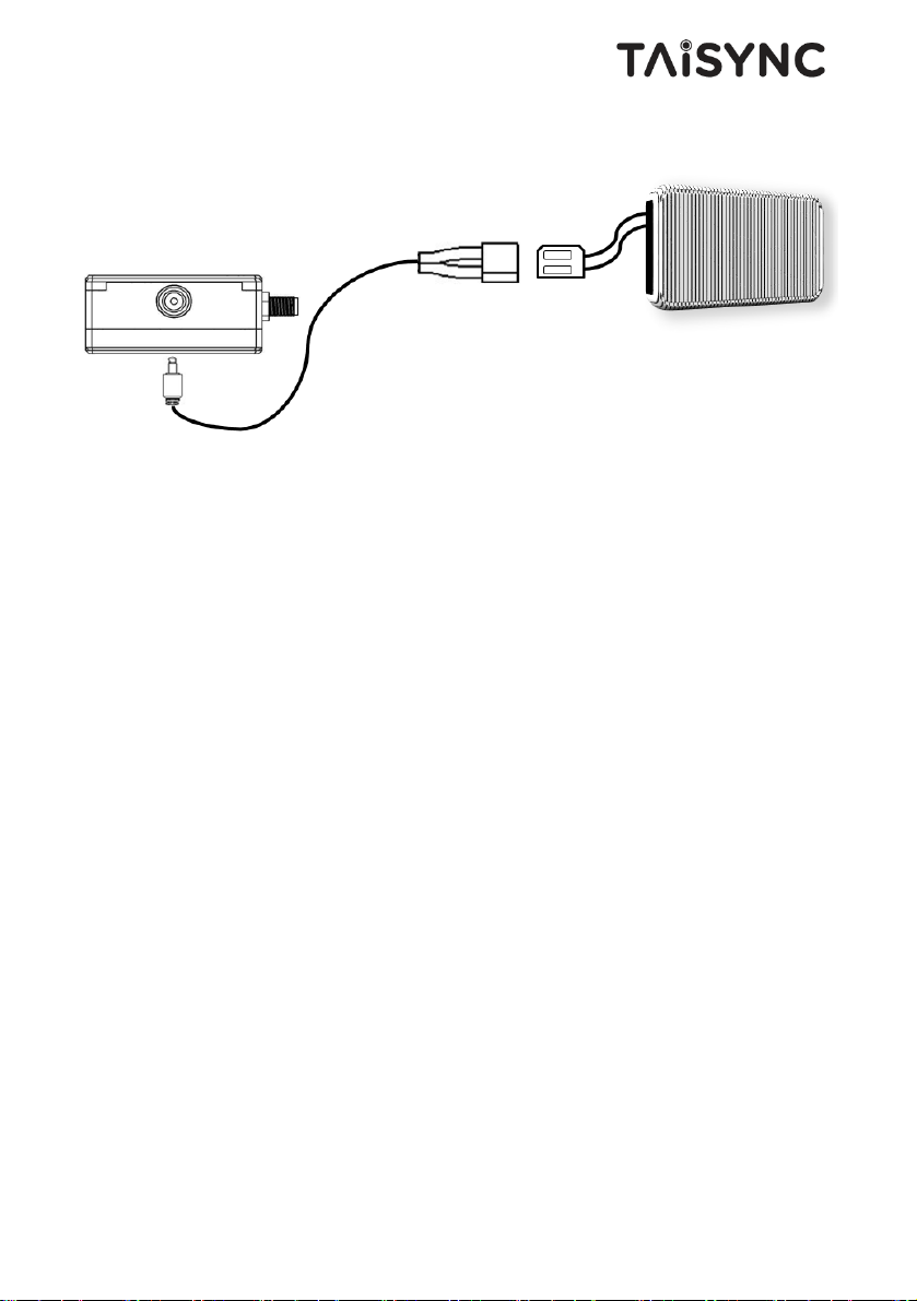
Insert the power connector of the power adaptor into the charging port of the ground unit and
insert into the aerial plug into an electrical outlet to fully charge the battery of ground unit.
Recommended voltage is 12V.
Note:
(1) Recommended rated voltage/current is DC12V/1.2A (or 3S lithium battery).
(2) To avoid equipment damage, install antennas before powering on the units.
Page 16
13
3.2.3. Telemetry connection
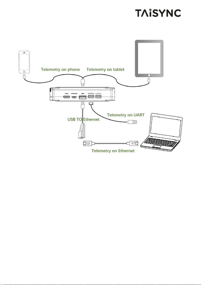
Insert the six-pin connector of supplied serial cable to the serial port of the ground unit and
connect the other end of supplied serial cable to the telemetry port of the ground control
station.
Note:
(1) Ensure the baud rate of ground station and the baud rate of Taisync module are
configured correctly.
(2) Ensure the serial cable sequence matches the interface definition of Taisync module.
Page 17
14
3.2.4. Connection to remote controller
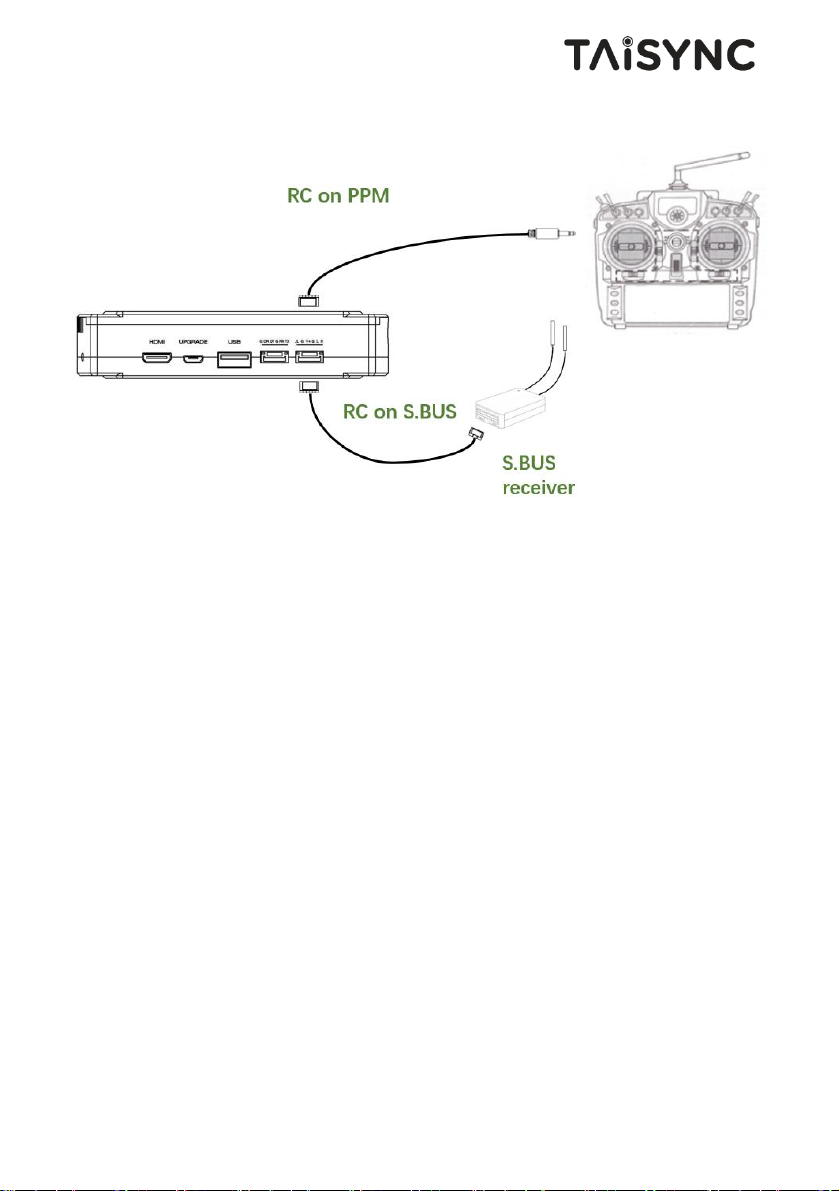
Using PPM mode: Insert the training connector of the supplied RC cable to the training port
of a remote controller and connect the six-pin connector of the RC cable to the RC port of
the ground unit.
Using S.BUS mode: Insert the six-pin connector of the RC cable to the RC port of the
ground unit, the other end connect the S.BUS receiver, and the S.BUS receiver
communicates with the remote controller in wireless communication.
Note:
(1) Ensure the remote controller is in training mode, it is configured to the PPM or S.
BUS working mode.
(2) Ensure the RC cable sequence matches the interface definition of Taisync module.
(3) If the S.BUS receiver is used, the working frequency of the receiver and the Taisync
module should be guaranteed with a certain degree of isolation.
Page 18
15
3.2.5. Setup video output
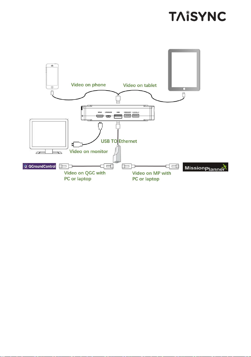
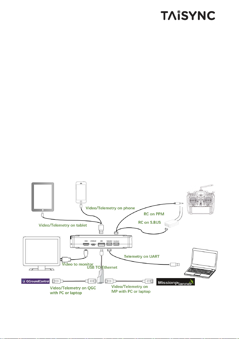
The ground unit outputs video to the monitor via HDMI cable, or you can connect the
ground unit to the mobile phone or tablet via USB cable, and opens Viulinx APP to watch
the video. QGC is also supported.
Video outputting can be supported on QGC or MP by using USB-Ethernet connector and
connecting PC or laptop through ethernet cable.
Note:
(1) If you use mobile phones or tablets to watch videos, please use Taisync's APP
Viulinx. QGC can also be supported.
(2) Using the USB-Ethernet connector, the corresponding ground station configuration is
needed.
Page 19
16
3.2.6. Use ViULinx Lite System
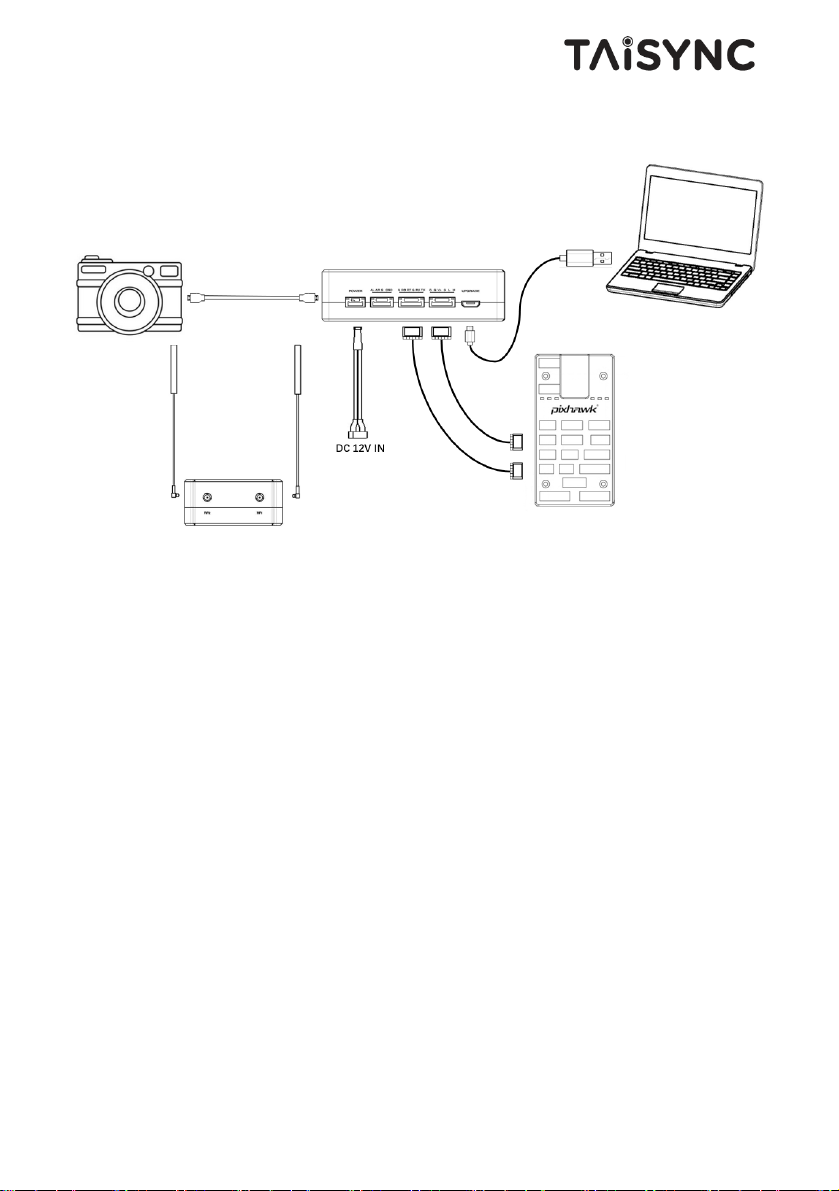
1. Connect antennas to RF ports of the air unit.
2. Connect camera HDMI output to HDMI port of the air unit.
3. Connect the PPM/S.bus port of the flight controller to the RC port of the air unit.
4. Connect the flight controller telemetry port to the serial port of the air unit.
5. Turn on the camera and set the video format to 720p or 1080p.
6. Connect a 12V DC power to the power port of the air unit and turn on the power.
7. If latest firmware is desired, connect the air unit to a PC or a Laptop using USB cable
and run ViuLinx
TM
PC program to upgrade the firmware of the air unit to the latest
one.
Page 20
17
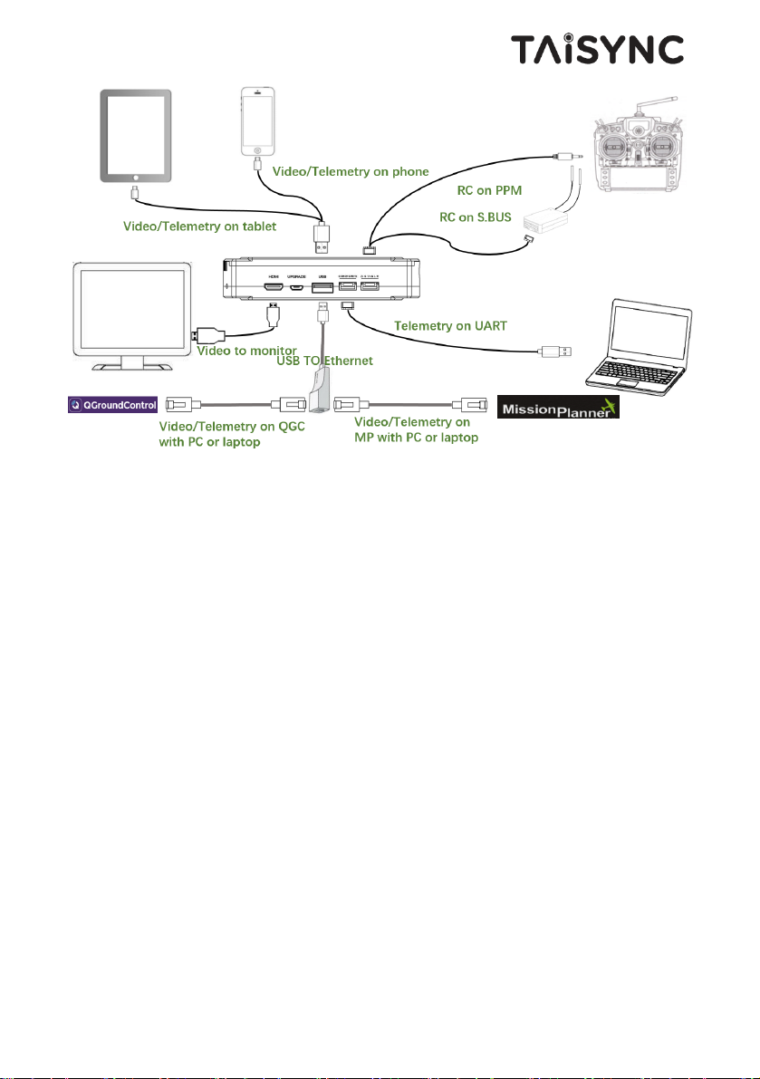
1. Connect antennas to RF ports of the ground unit.
2. Adjust the remote controller to the training mode, if PPM mode is used, the remote
controller interface at the ground end is connected to the training port of the remote
control. If S.BUS mode is used, the cable connection between the S.BUS receiver
and the ground end need to be established, and the connection between the receiver
and the remote control need to be established.
3. Connect the USB port of ground control station to the serial port of the ground unit
with TTL-USB cable if you want to use ViuLinx’s telemetry link.
4. Connect cell phone or tablet to the USB port of the ground unit.
5. If video view on a monitor is desired, connect a monitor to the HMDI port of the
ground unit.
6. Turn on the ground unit.
7. If latest firmware is desired, connect the ground unit to a PC or a Laptop using USB
cable and run ViULinx
TM
PC program to upgrade the firmware of the air unit to the
latest one.
8. After downlink and uplink are connected, both LEDs will be on.
9. Run ViuLinxTM APP on your phone or tablet. QGC is also supported. You can
watch the video on phone or tablet with ViuLinxTM or QGC APP.
Page 21
18
4. Software
4.1.Installation
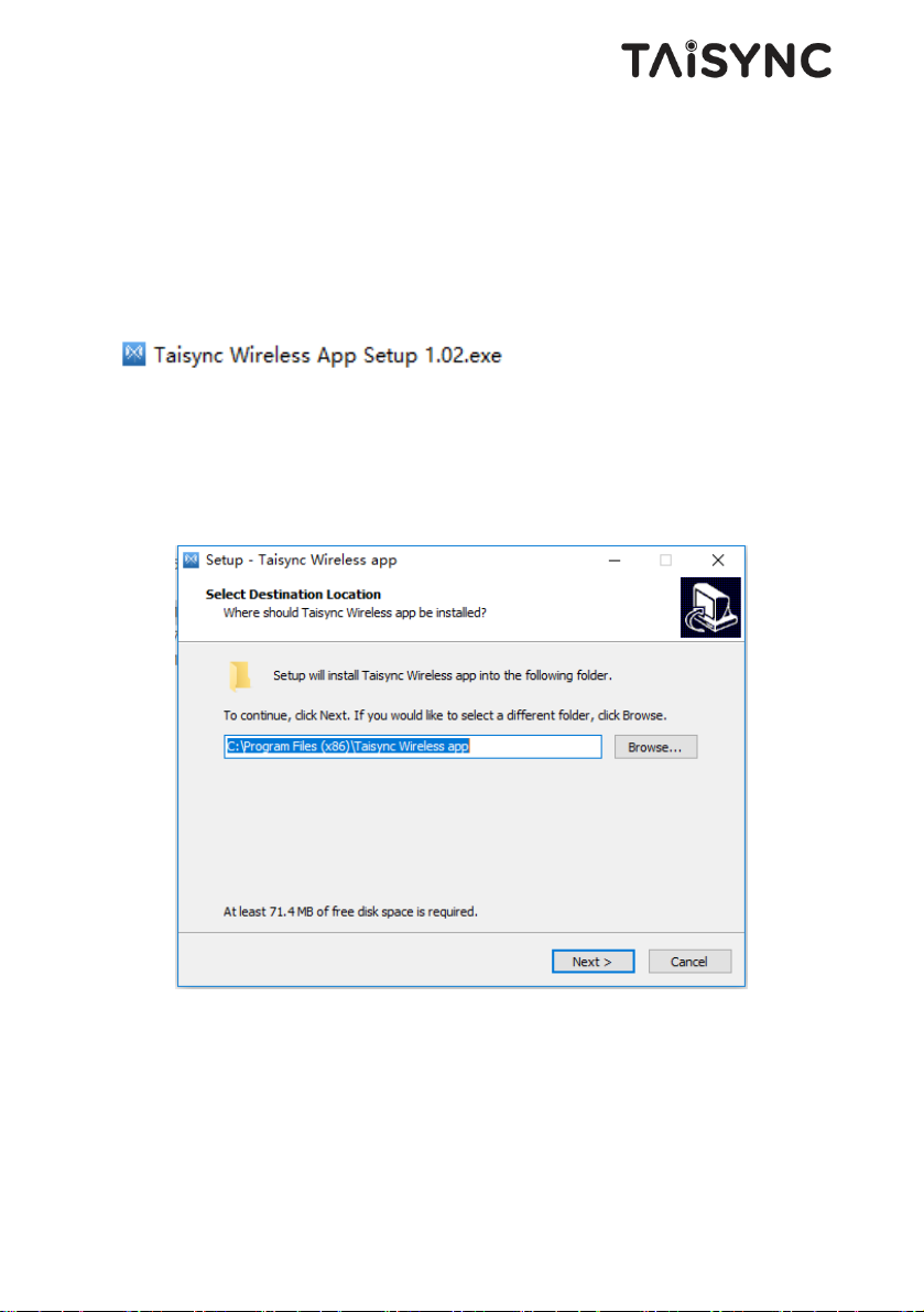
We provide program installation files, program file name: Taisync Wireless App Setup.exe.
The installer icon is as follows:
Double-click the installer to install and customize the program installation directory. After
configuration, click the “Next” button to jump to the next step. To cancel the installation,
click the “Cancel” button.
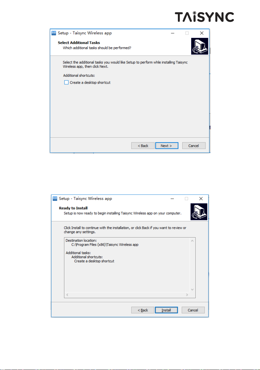
Check the Generate desktop shortcut. If it is not checked, the desktop shortcut will not be
generated. After configuration, click the “Next” button to jump to the next step. To rewind
the previous step, click the “Back” button. To cancel the installation, click the Cancel
button.
Page 22
19
Click “Install” to proceed with the installation. To rewind the previous step, click the “Back”
button. To cancel the installation, click the “Cancel” button.
Note: Please turn off the firewall software, otherwise the firewall may prevent the
driver from being installed when the driver is installed.
Page 23
20
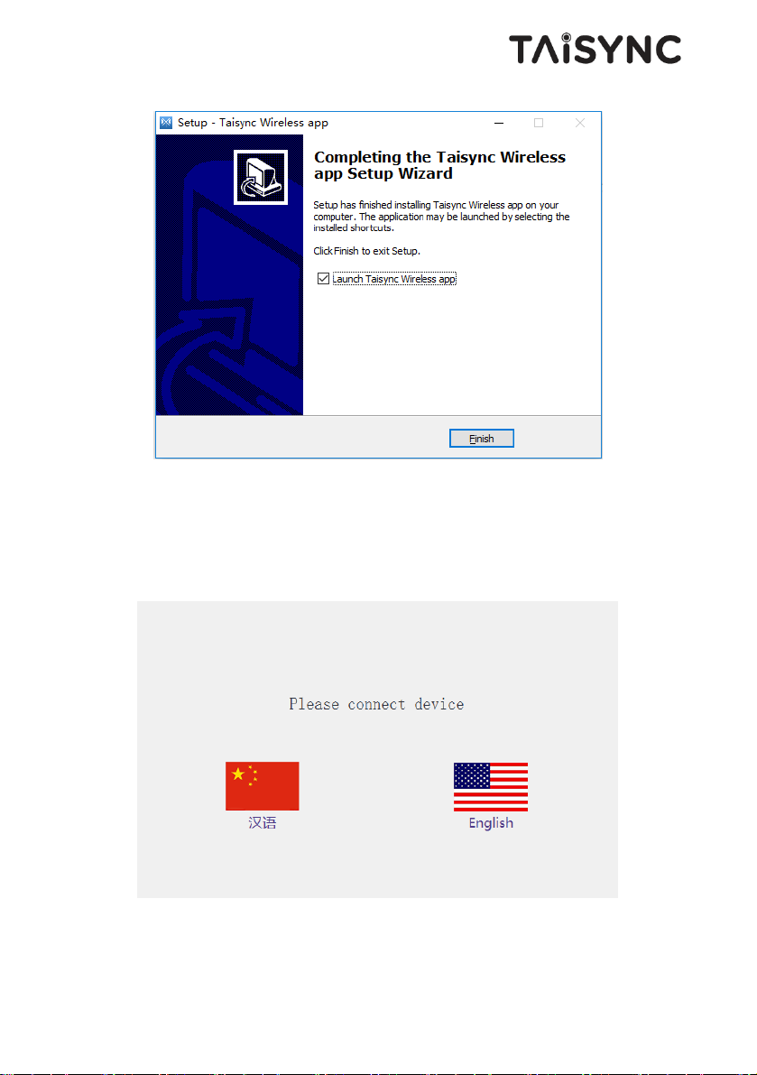
At this point, the software installation is successful and the driver installation is complete.
4.2.Language Selection
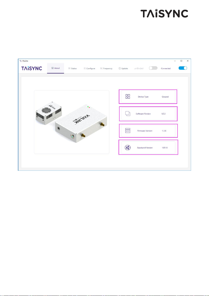
Software supports Chinese and English display.
Page 24
21
4.3.Device Info
Readable device status information: device type, software version, firmware version, and
baseband version.
4.4.Status
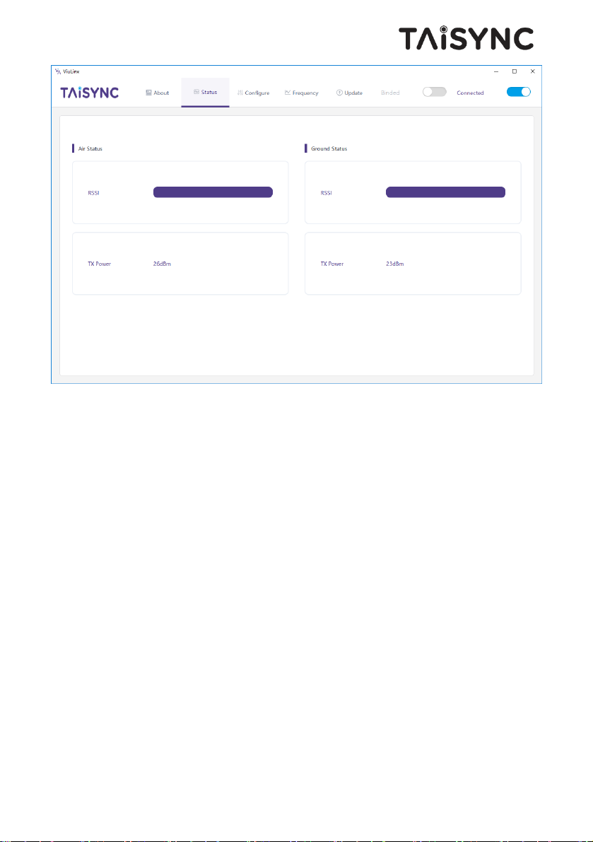
Read the air and ground status information, can read double-ended information: RSSI
(received signal strength indication), Tx_Power.
Page 25
22
4.5.Configuration
4.5.1. Mode configuration
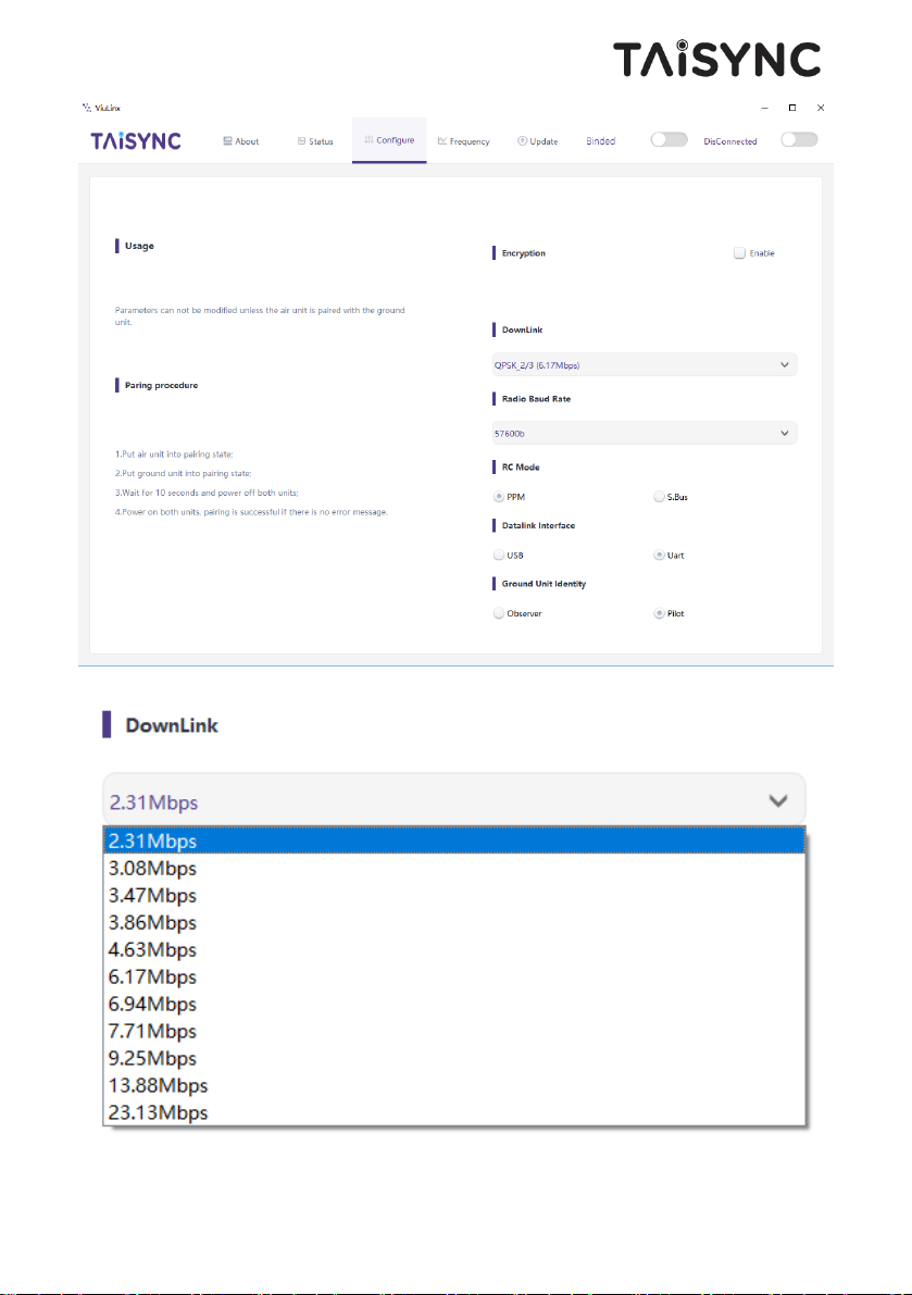
For parameter configuration, device bind is required.
Page 26
23
The downlink mode adjustment interface is as follows:
Page 27
24
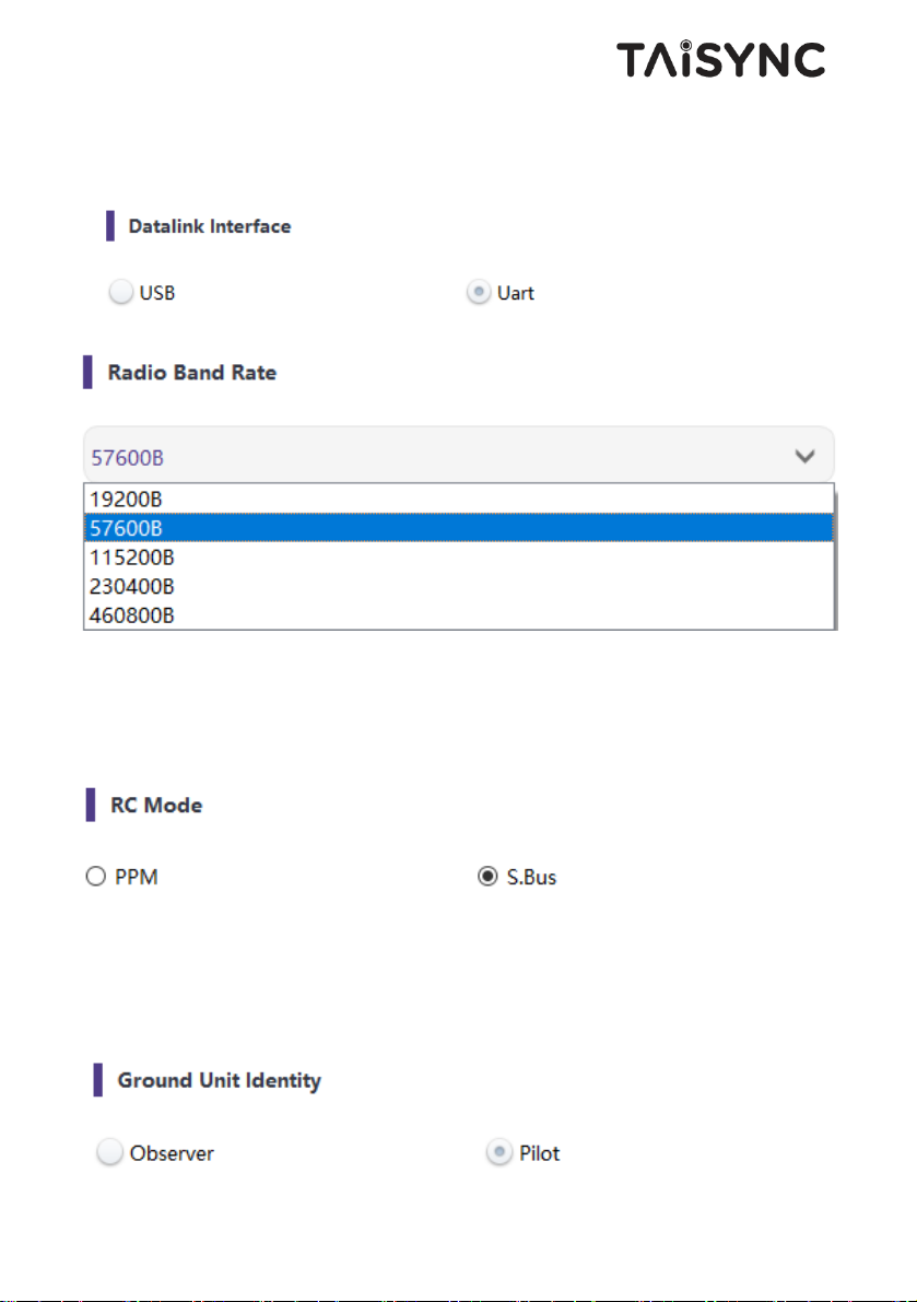
4.5.2. Telemetry configuration
Telemetry supported that can be on UART or USB.
Supported baud rate configuration:19200, 57600, 115200, 230400, 460800.
4.5.3. Remote control mode configuration
Supported remote control mode: PPM, S.bus.
4.5.4. Ground unit identity configuration
Ground unit can be configured as observer or pilot.
Page 28
25
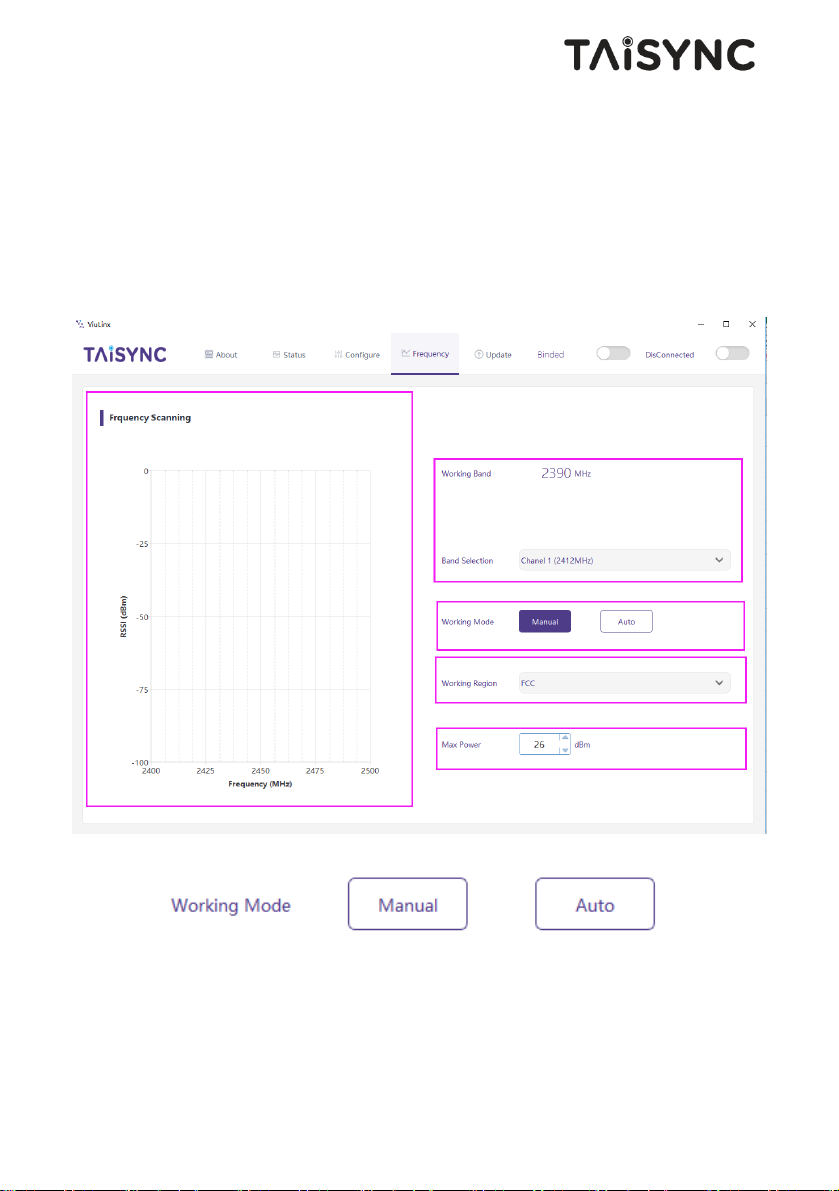
4.6.Frequency Scan
The left side is the frequency scan curve after the module starts. This interface display the
current working frequency, adjust the working frequency, adjust the frequency working mode,
the working region (FCC, CE) and the maximum TX power.
Working Mode:Manual, Auto.
Manual mode: The module administrator or user manually configures the working frequency.
Auto mode: The system configures the working frequency according to the frequency scan
curve.
Page 29
26
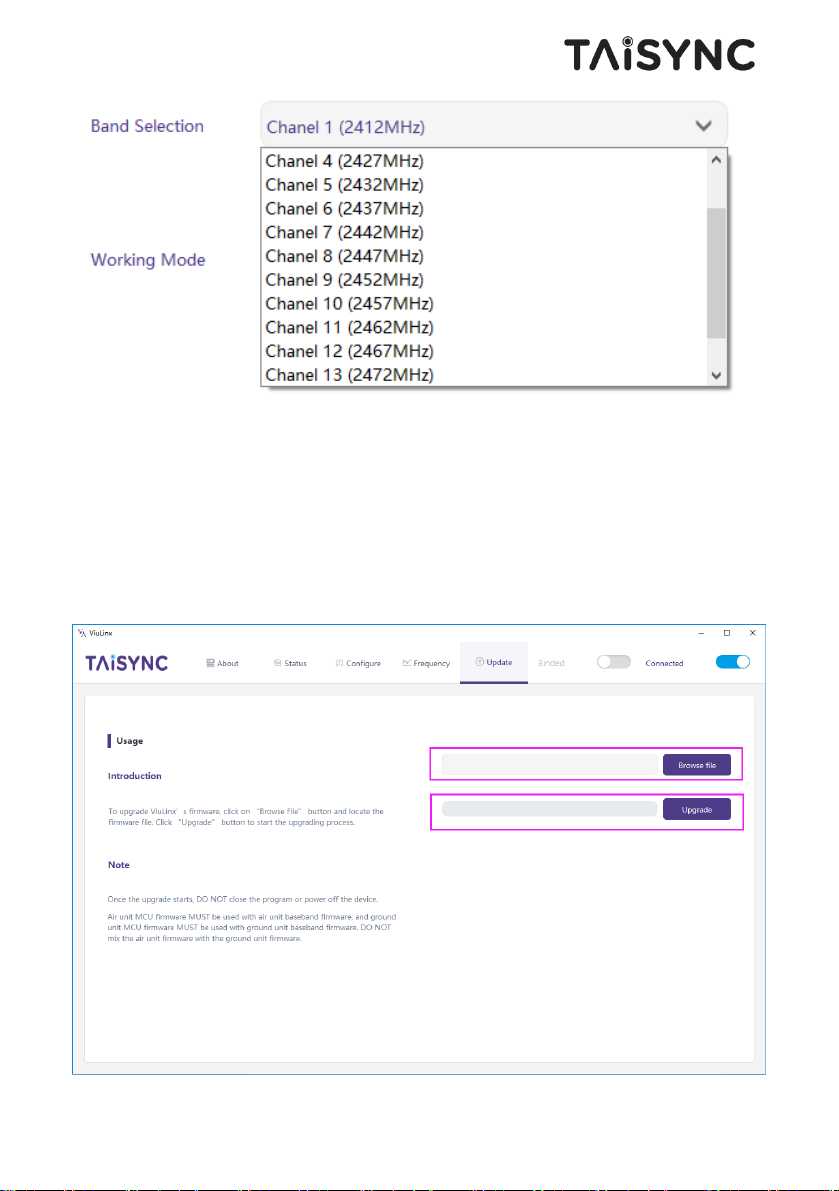
4.7.Upgrade
Note: air and ground upgrades need to be upgraded separately using the USB cable to connect
Taisync PC software.
Select the upgrade file, click the Upgrade button to upgrade.
Page 30
27
4.8.View Live Video
4.8.1. On phone/tablet
Connect cell phone to the micro USB port of the ground unit. Run ViULinxTM APP on your
cell phone. QGC is also supported.
4.8.2. On monitor
Connect a monitor to the HMDI port of the ground unit.
5. Applications
5.1.Applications of system in detail
Page 31
28
5.2.Applications of RC
The remote control function can support PPM and S. BUS protocol.
If PPM mode is used, please use Taisync standard PPM cable to connect the ground unit and the
remote controller's training port.
If S. BUS mode is used, additional receiver supporting S. BUS is needed. The ground unit is
connected with the receiver. The S. BUS receiver establishes wireless communication with the
remote controller.
Both modes require the remote controller to configure the corresponding mode.
If using S. BUS receiver, please use a receiver which working frequency is different from
Taisync module.
5.2.1. FRSKY remote controller
PPM mode
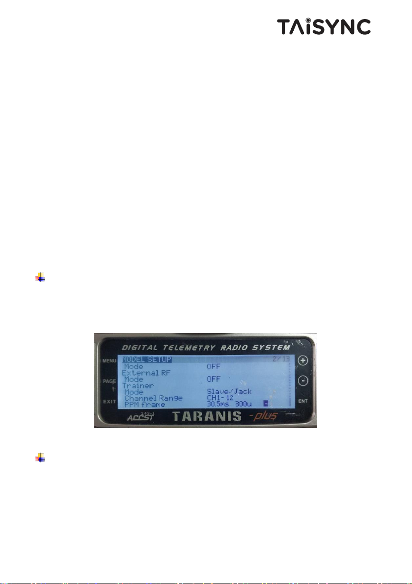
Model setup - Trainer - mode, if mode is configured to Slave/Jack, then the remote controller is
in PPM mode.
Model setup - Internal RF, it is needed to be configured to off, S. bus mode will be closed.
S.BUS mode
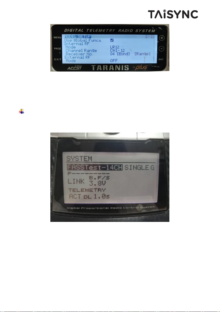
Model setup - Internal RF: LR12, D8, D16, OFF. Configuration of different parameters is
according to the receiver. If configured as off, S. bus mode will be closed.
Page 32
29
5.2.2. Futaba remote controller
S.BUS mode
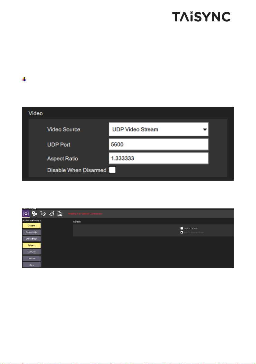
Linkage menu - system: FASSTest-14CH, FASSTest 12CH, FASST MULTI, FASST 7CH, SFHSS. Configuration of different parameters is according to the receiver.
5.3.Video output on USB (standard)
Standard mode: connect to mobile phone or tablet with USB cable, display video with Viulinx
APP of Taisync.
Taisync also supports video display on QGC APP (mobile phone and tablet) and telemetry on
QGC.
Page 33
30
5.4.Video output on USB (optional, USB To ETH)
Video can be played on QGC or Mission Planner via USB to ETH. This version requires
different versions of firmware. If you need to use this function, please contact Taisync to
provide technical support.
Video on QGC (QGroundControl)
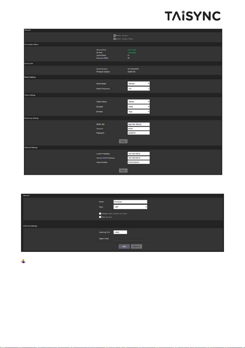
Please set the IP Address of a PC or laptop to 192.168.199.33.
Video source: UDP Video Stream, UDP port 5600.
If there is no video configuration subitem, please confirm that the Enable Taisync item is not
checked in the Taisync directory.
Through the Taisync item, we can get the connection status of the device, device information,
video configuration, video source configuration and IP configuration.
Page 34
31
Telemetry on USB to ETH, the type adjusts to UDP, listens on port 14550.
Video on Mission Planner
Please set the IP Address of a PC or laptop to 192.168.199.33.
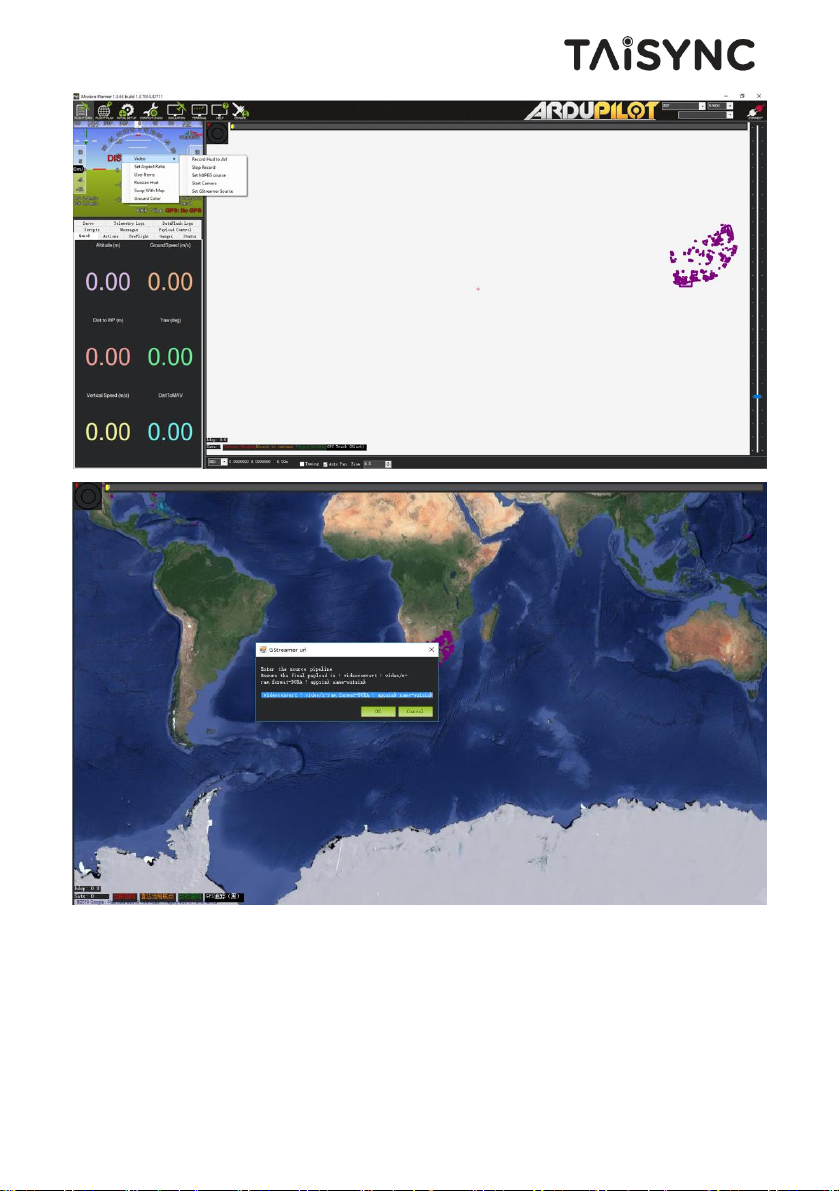
Right-click on the image area, select Video-Set GStreamer Source.
Page 35
32
GStreamer url: gst-launch udpsrc port=5600 ! application/x-rtp ! rtpjpegdepay ! videoconvert !
video/x-raw,format=BGRA ! appsink name=outsink.
When using this function for the first time, the program will update the plug-in. After updating,
the Mission Planner program needs to be restarted to play the video.
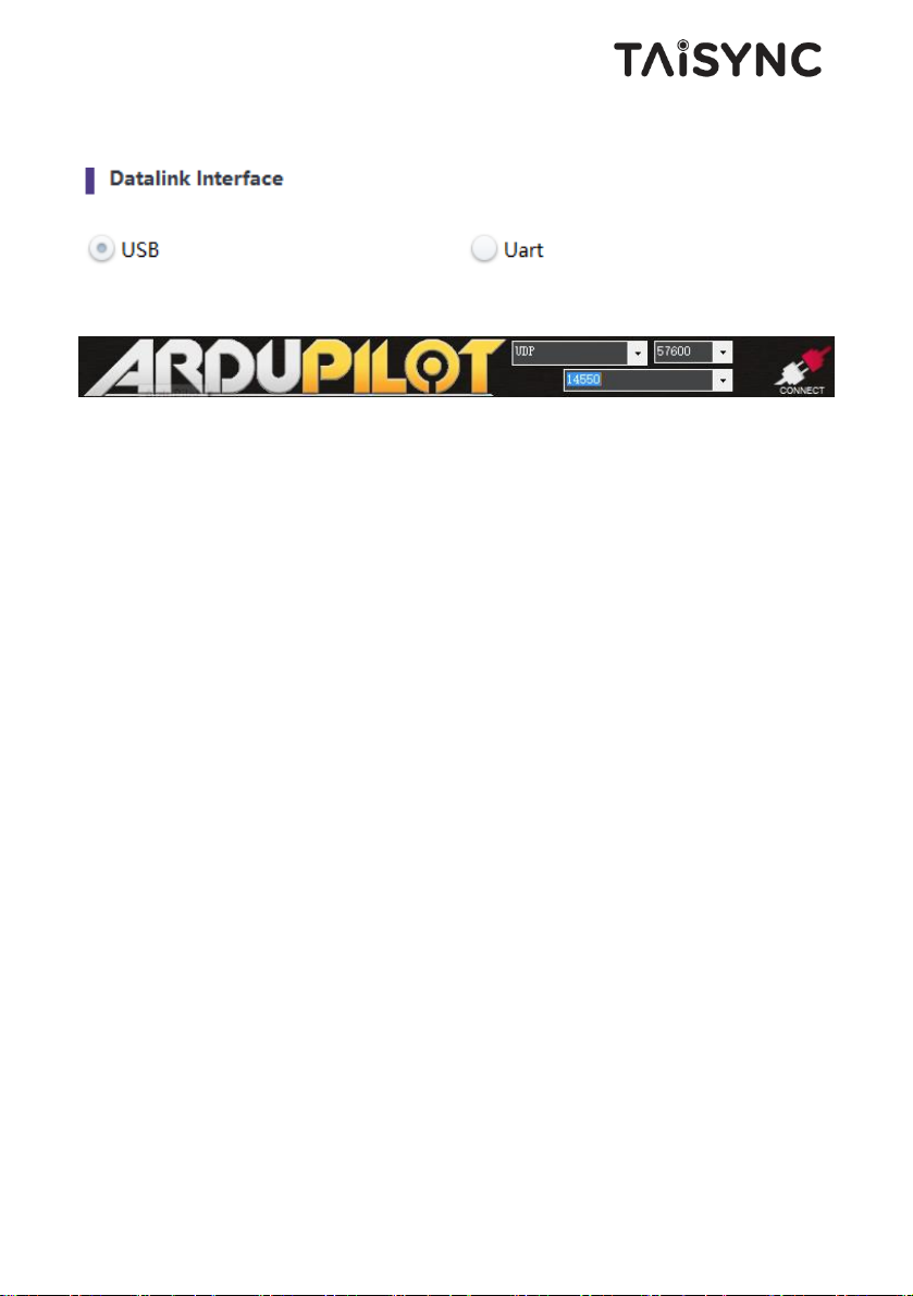
Telemetry on ETH:
Page 36
33
It is needed to adjust the datalink interface to the USB interface with Taisync management
software.
UDP, 14550.
6. Notes
6.1.Link performance
Interference by 2.4GHz WiFi
WiFi operates at 2.4GHz band with bandwidths of 20MHz and 40MHz. WiFI can generate both
co-channel interference and adjacent channel interference to the 2.4GHz wireless link of a
drone. Even if there is not a WiFi router is available for a WiFi device (for example, WiFi of a
phone) to connect with, a WiFi device periodically transmits beacon/probe signals. So, when
you operate a drone in the field with 2.4GHz wireless link, it is important to turn off WiFi
modem/hotspot of a phone, or a laptop. If WiFi relay of the video from the ground station is
desired, it is recommended to use a 5.8GHz WiFi modem.
Interference by Bluetooth device
Bluetooth operates on 2.4GHz in frequency hopping mode. So a Bluetooth mouse, Bluetooth
joystick, or any Bluetooth device that is actively working and next to ground station will
interfere the reception of downlink video. Please avoid using Bluetooth device when operate a
drone with 2.4GHz wireless link.
Interference by wireless device in co-existence
Page 37

34
Another wireless device that operates on bands close to 2.4GHz and the device is placed close
to the drone’s 2.4GHz wireless module can interfere the drone’s wireless link. For example,
some drones have both LTE link and point-2-point wireless link. Particularly, the LTE
operating on 2.3GHz band can be a problem. If the antenna of the LTE module is placed close
to the antenna of the 2.4GHz point-2-point wireless module, the receiver of 2.4GHz module can
be saturated by the LTE signal when it is transmitting. Thus, the range/performance of the
2.4GHz module will be significantly degraded.
Interference by HDMI
When HDMI source/cable is close the antenna of 2.4GHz wireless modem, the HDMI
source/video will interfere the 2.4GHz wireless signal (including WiFi).
https://h30434.www3.hp.com/t5/Notebooks-Archive-Read-Only/HDMI-interfering-with-WiFiconnectivity/td-p/4535026
http://www.dslreports.com/forum/r27141612-HDMI-connect-interferes-with-wifi
It is recommended that install the antenna at least 25cm away from the HDMI source/cable. A
good shield HDMI cable can be a resolution too. The following shield HDMI cable uses 360degree shield termination, which is recommended practice.
https://interferencetechnology.com/hdmi-cables-emi/
http://www.l-com.com/content/Article.aspx?Type=P&ID=10699
http://www.l-com.com/audio-video-micro-hdmi-to-hdmi-cables
http://www.l-com.com/audio-video-hdmi-female-to-micro-hdmi-male-adapter
RF cable connector/Antenna connector check
Before flight, check if the antennas are connected to the modules. Running module without
antenna connected results in very short range and potentially can damage the module. It is
recommended to check the connection of all RF connectors. Loose connection can degrade the
range significantly.
Antenna placement
Page 38
35
Place the two air antennas so that no matter what position the drone is, at lease one antenna is
not blocked by the payload from the ground station.
If the drone will fly in full throttle, it will lean forward. Install the air antenna so that it is close
to be vertical to the ground when the drone moves forward in full throttle.
Battery level of ground station
The reception performance will degrade if the battery of ground station runs low, even though it
might still power the wireless ground unit up.
6.2.How to select Frequency
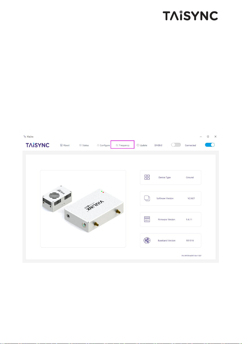
Click “Frequency” buttion using Viulinx APP.
On the left, you can see the RSSI curve of frequency scan.
Scan range: 2.4G WIFI bands.
The lower the RSSI value of the corresponding frequency points, the lower interference.
Please select the lowest interference frequency.
Page 39
36
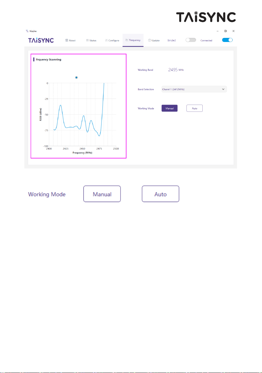
Working Mode:Manual, Auto.
Manual mode: The module administrator or user manually configures the operating frequency.
Auto mode: The management software configures the optimal working frequency according to
the frequency scan information.
Please make sure working mode is on manual mode.
Page 40
37
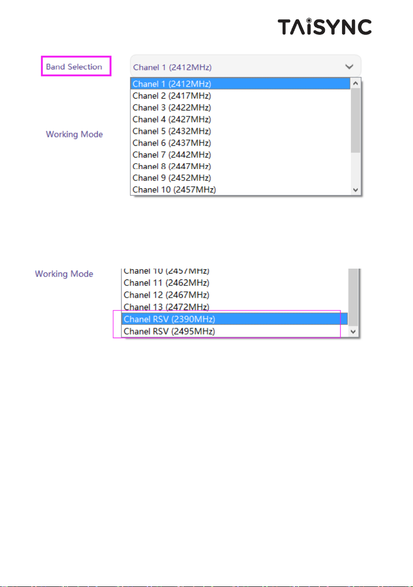
We can select working frequency by band selection function.
We provide 2390MHz and 2495MHz reserved frequency.
If WiFi interference is too high, you can consider using reserved frequency.
6.3.Firmware update
Upgrade files: FPGA upgrade file for air unit, FPGA upgrade file for ground unit, MCU1
upgrade file for air unit, MCU1 upgrade file for ground unit, MCU2 upgrade file for air unit,
MCU2 upgrade file for ground unit, Hi3516 upgrade file for air unit, Hi3798 upgrade file for
ground unit.
Hi3798 upgrade file for ground unit is upgraded with U disk. The fastboot. bin file needs to be
added to the root directory of the U disk, and the upgrade file is renamed update. bin. When the
ground unit is powered on, insert the U disk into the USB port. The LED lamp of the ground
unit will appear green flashing, indicating that it is in the upgrade process. When upgrade is
completed, the LED lamp will no longer flashing. The upgrade process is expected to last 7-8
minutes.
Page 41

38
Other files are upgraded using management software. During the upgrade process, the power
can not be powered off and the normal connection of USB cable should be ensured at the same
time. If the upgrade fails, the power can not be powered off, please try to upgrade again
directly. Otherwise, it will be necessary to return to us to use special burning tools for firmware
burning.
6.4.Bind operation
“Bind” is used to pair an air unit with ground unit.
To pair an air unit and an ground unit:
1. Both air unit and ground unit are powered on.
2. Connect the air and ground unit.
3. Press the physical bind button of the air unit, last 3-5s. The LED light next to the bind
button flashes green, indicating that it is in the binding state.
4. Press the physical bind button of the ground unit, last 3-5s. The LED light next to the
bind button flashes green, indicating that it is in the binding state.
5. When the link indicator LEDs of ground unit are always on, it indicates that the air
and gournd unit is binded. Then power off both units.
6. Power on both units. Link indicator lights are always on, indicating bind operation of
the air and ground units are completed.
Note:
(1) If modules binding with different firmware version, the binding operation may fail.
(2) If the program of the air unit or the ground unit is burned incorrectly, such as burning
the air unit to the ground unit, and performing the binding operation between the wrong
air unit and the ground unit, the binding operation will fail.
6.5.Telemetry & RC
Telemetry
UART singal: LVCMOS-3.3V.
Pin-out: G DR DT G RX TX.
Debug-DR/DT, Telemetry-RX/TX.
Page 42
39
RC
Pin-out: II G V+ G L H.
II: PPM/SBUS G: GND V+: POWER(5V) G: GND L: CAN-bus-L
H: CAN-bus-H (CAN-bus is not supported yet).
The RC port can provide 5V power supply for S. BUS application.
7. FAQ
Q1: How to install management software and driver, and how to use management software?
Please read Chapter 4 of this document.
Q2: How does the Taisync module supply power?
Air unit: DC, power supply range: 8-15V, recommended to use 12V, Taiysnc provides power
supply cables.
Ground unit: DC, power supply range: 8-15V, recommended to use 12V, Taiysnc provides
power supply cables.
Q3: Can the Taisync module be powered on before antennas installation?
The antennas must be installed before power on.
Q4: How many antennas do Taisync's air unit need to be installed?
Two antennas need to be installed.
Q5: How many antennas do Taisync's ground unit need to be installed?
Two antennas need to be installed.
Q6: Can different types of remote controllers be used to control drone?
Yes, just output standard PPM signals through the coach port, or use S. BUS receiver.
Q7: Video compression protocol supported by Taisync module?
H.264 & H.265.
Q8: Can two air units be installed on a drone?
No, a drone can only integrate one air unit.
Q9: Can two ground units be installed at the receiving end?
The ptp system can only install one ground unit; the ptmp system supports more than one
ground units.
Page 43
40
Q10: There are some devices nearby, such as WIFI, Bluetooth and so on. Can they be opened
when flying?
Be sure to turn off WIFI, Bluetooth and other functions of other devices, because these
devices are working in 2.4 GHz band, It can cause interference.
Q11 After integrating the Taisync air unit, GPS is not good at searching for stars. What
should we do?
Please check whether the antennas of air unit is far away from GPS to avoid blocking
interference to GPS. The frequency band of 1.4G module is close to working frequency of GPS, so
it is necessary to ensure a certain degree of antenna isolation.
Q12: What do the two LED lights of the ground unit stand for?
LED 1 (downlink Indicator): The LED is on indicates that the air-to-ground link is connected;
the LED is not on indicates that the air-to-ground link is disconnected.
LED 2(uplink Indicator): The LED is on indicates that the ground-to-air link is connected; the
LED is not on indicates that the ground-to-air link is disconnected.
Q13: What if the uplink LED indicator is not on?
Please follow the following steps:
1) Please check the power supply of the air and ground unit is normal.
2) Please check the antennas installation of the air and ground units is normal: whether the
antennas is blocked; whether the antennas connection is loose; whether the rf cable and port is
not tightened;
3) Check whether the TX frequency of the ground unit is consistent with the RX frequency of
the air unit with Taiysnc PC management software.
4) Check the TX power of the ground unit with Taiysnc PC management software.
5) If the above steps can not solve the problem, please contact Taisync technical support
staff.
Q14: What if the downlink LED indicator is not on?
Please follow the following steps:
1) Please check the power supply of the air and ground unit is normal.
2) Please check the antennas installation of the air and ground units is normal: whether the
antennas is blocked; whether the antennas connection is loose; whether the rf cable and port is
not tightened;
3) Check whether the TX frequency of the air unit is consistent with the RX frequency of the
ground unit with Taiysnc PC management software.
4) Check the TX power of the air unit with Taiysnc PC management software.
5) If the above steps can not solve the problem, please contact Taisync technical support
staff.
Page 44
41
Q15: After connecting Taisync module, telemetry can not be connected properly?
Please follow the following steps:
1) Please check whether the link state is normal, please refer to Question 13 and Question
14 if it is abnormal.
2) Please check whether the telemetry port both the air and the ground units is correct.
3) Please check whether the connecting between flight controller and air unit is correct and
that between ground unit and ground station is correct.
4) Please check whether the telemetry connection of the air and ground unit is correct. We
provides standard cables. If you make it by yourself, please check the pin.
5) Check whether the baud rate is configured correctly with Taiysnc PC management
software.
6) If the above steps can not solve the problem, please contact Taisync technical support
staff.
Q16: After connecting Taisync module, RC can not be connected properly?
Please follow the following steps:
1) Please check whether the link state is normal, please refer to Question 12 and Question
13 if it is abnormal.
2) Please check whether the RC port both the air and the ground units is correct.
3) Please check whether the RC connecting between flight controller and air unit is correct
and that between ground unit and remote contriller is correct.
4) If using PPM mode, check the mode configuration of the remote controller; if using S.
BUS mode, check the configuration of the receiver and remote controller;
5) Please check whether the RC connection of the air and ground unit is correct. We
provides standard cables. If you make it by yourself, please check the pin.
6) Please check whether the RC mode is configured correctly with Taiysnc PC management
software.
7) If the above steps can not solve the problem, please contact Taisync technical support
staff.
Q17: After connecting Taisync module, video can not be output properly?
Please follow the following steps:
1) Please check whether the link state is normal, please refer to Question 13 and Question
14 if it is abnormal.
2) Please check whether the HDMI cable and camera is normal;
Page 45
42
3) Please check whether the phone or HDMI connection is correct, and whether Viulinx APP
is used;
4) If the above steps can not solve the problem, please contact Taisync technical support
staff.
Q18: After connecting Taisync module, what if the video carton or mosaic?
Please follow the following steps:
1) Please confirm whether the downlink mode configuration is reasonable;
2) Please check whether the HDMI connection of air unit cable is normal;
3) Whether the connection of HDMI or USB cable of ground unit is normal;
4) Please check If there is interference exsit, we can consider changing the working
frequency.
5) If there is no interference, whether the limit distance of communication link has been
reached;
6) If the above steps can not solve the problem, please contact Taisync technical support
staff.
Q19: After connecting Taisync module, what if the transmission distance of the module is
short, which is not up to expectation?
Please follow the following steps:
1) Please verify whether the antenna and RF cable are installed correctly, check whether they
are Taisync standard materials;
2) Please ensure that the antennas installation of air unit is not blocked by the payload, and
there is no obvious blocking at the ground unit near the antennas, and the antennas of the air
and ground units are perpendicular to the ground;
3) Please check whether the RF power is reduced, not to achieve full RF power;
4) Please check whether the downlink mode configuration is reasonable or not, the highspeed downlink mode will significantly reduce the transmission distance;
5) Please check whether the working frequency is obviously interferenced or not, Chapter
6.2 introduces how to select working frequency.
6) Please check whether there is serious obstruction between the air and the ground unit
during flighting, and the complex geographical environment will affect the transmission distance;
7) If the above steps can not solve the problem, please contact Taisync technical support
staff.
 Loading...