

Page 1

TAINET
WANpro 2000i
IDSL / Broadband Access ROUTER
USER'S MANUAL
The Professional Partner
TAINET COMMUNICATION SYSTEM CORP.
Headquarters:
No. 25, Alley 15, Lane 120,
Sec. 1. Nei-Hu Rd,
Taipei 114, Taiwan
TEL: 886-2-26583000
FAX: 886-2-26583232
Beijing Branch:
3F, A Building, 113 Zhi Chun Lu,
HaiDian District, Beijing, China
Zip Code: 100086
TEL: 86-10-62522081~87
FAX: 86- 10-62522077
V1.3 09004-00018 2004/03/24
Page 2

Copyright © 1999 Tainet Communication Corporation.
All rights reserved.
Printed in Taiwan R.O.C.
Notice
This document is protected by the international copyright law. No part of this
publication may be reproduced by any means without the permission of Tainet
Communication Corporation.
TAINET is a registered trademark, and “WANpro 2000i” is a trademark of Tainet
Communication Corporation.
Other product names mentioned in this manual are used for identification purposes only
and may be trademarks or trademarks of their respective companies.
The information provided from Tainet Communication Corporation is believed to be
accurate. Any changes and enhancements to the product and to the information thereof
will be documented and issued as a new release to this manual.
i
Page 3

FCC NOTICE
This equipment has been tested to comply with limits for a digital device, pursuant to
Part 15 of the FCC Rules. These limits are designed to provide reasonable protection
against harmful interference when the equipment is operated in a commercial
environment. This equipment generates, uses, and can radiate radio frequenc y energy
and, if not installed and used in accordance with instruction manual, may cause
harmful interference to radio communication.
If the equipment does cause harmful interference to radio or television devices, the
user is encouraged to try to correct the interference by one or more of the following
advises:
1. Reorient or relocate the receiving antenna.
2. Increase the separation between the equipment and receiver.
3. Connect the equipment into an outlet on a circui t different from that to which
the receiver is connected.
4. Consult the dealer or an experienced radio/TV technician for help.
The FCC Rule is available from the U.S. government Printing Office, Washingt on, DC
20402, Stock NO. 004-00000345-4.
The shielded RS-232 cable is to be used in order to ensure complian ce with FCC Part
15, and it is the responsibility of the user to provide and use shielded RS-232 cable
from NTU to personal computer.
We will not commit to repair this unconditional fault resulting from the user. The
warranty issue will only protect for right operations mentioned in the manual, and extra
charge for this fault might be noticed if necessary.
Any changes of modifications not expressly approved by the grantee of
this device could void the user’s authority to operate the equipment.
ii
Page 4

W ARRA NTY AND SERVICE
Contact:
If there are any questions, contact your local sales
representative, service representative, or
distributor directly for any help needed. You might
use one of the following methods..
Via the Internet: visit our World Wide Web site at http://www.tainet.net
Via the Sales Representatives:
HQ
No. 25, Alley 15,. Lane 120, Sec. 1. N-e-is-H-u Rd. Taipei, Taiwan, R.O.C.
TEL: (886) 2-2658-3000 E-mail: [email protected]
FAX: (886) 2-2658-3232 URL: http://www.tainet.net/
Beijing Branch
3F, A Building, 113 Zhi Chun Lu,
HaiDian District, Beijing, China
Zip Code: 100086
TEL: (86) 10-62522081~87 E-mail: [email protected]
FAX: (86)
10-62522077 URL: http://www.tainet.com.cn
Moscow Branch
111024, Shosse Entuziastov Building 14, Room 425, Moscow, Russia
TEL: (7) 095-7850-377 URL: http://www.tainet.ru
FAX: (7) 095-7850-378
iii
Page 5

Preface
About your IDSL Internet Access Router
Congratulations on your purchase of the WANpro 2000i IDSL Router. For free future product
updates and information please visit our online web site http://www.tainet.net
The WANpro 2000i is an IDSL router used for WAN/LAN access via an 2-wire lease line, as
well as WAN serial interface (Optional) allows you to connect CSU/DSU or modem for Sync. or
Async. data translation up to 1 MBps. The WANpro 2000i supports TCP/IP routing protocol.
The WANpro 2000i router supports symmetrical multi-rate data transmission speeds of 64 kbps
or 128 kpbs. WANpro 2000i use 2B1Q line code with echo cancellation for high data rate
transmissions over a single twisted copper pair, it also provides high immunity from background
noise.
The WANpro 2000i provide 10 Mbps auto-negotiating LAN interface enables fast data transfer
in either half-duplex or full-duplex mode depending on your Ethernet network.
Your WANpro 2000i is easy to install and to configure via front panel for simple function or full
functions of WANpro configurable via the TCS (Terminal Configuration Syetem) interface.
This user's manual covers all operations of the WANpro 2000i and shows you how to get the best
out of the multiple advanced features of your IDSL Internet Access Router. It is designed to
guide you through the correct configuration of your WANpro 2000i for various applications.
What is IDSL
ISDN Digital Subscriber Line provides DSL technology over existing ISDN lines. Even though
the transfer rates for IDSL are about the same as ISDN (144kbps v. 128kbps), and IDSL circuits
typically only carry data (not voice), the major benefits of switching to IDSL from ISDN are
always-on connections, thus eliminating call setup delays; flat rate billing, instead of per minute
fees; and transmission of data over the data network, rather than the PSTN.
IDSL was developed by Ascend Communications, now part of Lucent Technologies.
iv
Page 6

Specifications
Software
PPP (RFC 1661, RFC 1662)
Frame Relay
Multi-protocol Interconnect over Frame Relay (RFC 1490)
HDLC packet-based format link layer,
Three generally implemented specification of Local Management Interfaces (LMI)
ANSI T1.617 Annex D
CCITT (ITU-T) Q.933 Annex A
LMI (Frame Relay Forum implementation agreement)
The eight multi-connection of virtual link by Data Link Connection Identifier (DLCI) at the most, and Permanent
Virtual Circuit (PVC) only
Routing
TCP/IP with RIP1 (RFC 1058), RIP2 (RFC 2543) or static routing on the LAN, WAN and/or IDSL interface, up to
16 static routes with default route and the option to not advertise routes
Dynamic Host Configuration Protocol
DHCP Server: automatic assignments of IP address, mask, default gateway, DNS server address, and WINS server
address to work stations (RFC 2131, RFC 2132)
IP Address T ranslation
NAT/NAPT (Network Address and Network Address Port Translatio n) (RFC 3022):
Provide enhanced security and flexibility by “hiding” all IP address on the LAN behind a single statically on the
Internet. Sophisticated extension NAT that provide security of a NAT “wall” to hide LAN IP addresses while
providing flexible use of all addresses offered by Internet Service Provider (ISP)
Security
Static IP Filter (Incoming and Outgoing)
Management
SNMPv1 (RFC 1157) and MIB II (RFC 1213)
TELNET (RFC 854)
ICMP Ping (RFC 792)
Local management through Console port
v
Page 7

Hardware
LAN Interface
Ethernet 10 Base-T (RJ-45)
WAN Interface
Provides various DTE interface module (DB-25)
Synchronous and Asynchronous data format
The DTE interface Module include
V.35 speed up to 1Mbps (Sync)
X.21 speed up to 1Mbps (Sync)
EIA-530 speed up to 1Mbps (Sync)
RS-232 speed up to 128Kbps (Sync)
RS-232 speed up to 115200bps (Async)
IDSL Interface
ISDN Digital Subscriber Line interface (RJ-45)
Multi-rate symmetric speeds available at 64Kbps and 128Kbps
Line coding: 2B1Q IDSL Transceivers
Standards-based A NSI T1.601
2-wire full duplex operation using echo cancellation technique
Operation range up to 7.8Km over 0.5mm wire (24 AWG)
Console Port
RS-232 DCE (RJ-45)
Asynchronous VT-100 or ANSI emulation
Data rate: 19200N-8-1
Front Panel
Menu-driven via 5 buttons
2x16 characters with back-light LCD display
LED Display
LAN LINK Indicates link-state of LAN interface
LAN TXD Indicates packet transmit of LAN interface
LAN RXD Indicates packet receive of LAN interface
IDSL LINK Indicates link-state of the BRI U-interface of IDSL interface
IDSL TXD Indicates packet transmit of IDSL interface
IDSL RXD Indicates packet receive of IDSL interface
WAN LINK Indicates link-state of the PPP of WAN interface
WAN TXD Indicates physical line signal of data transmit of WAN interface
WAN RXD Indicates physical line signal of data receive of WAN interface
CONSOLE Indicates link-state of Console interface to terminal
Processor
20MHz Motorola MC68302
1MByte Flash memory and 2Mbyte DRAM
vi
Page 8

Physical
Dimensions: 48 x 180 x 262mm (Height x Width x Depth)
Weight: 0.9kg
Power Requirements
Internal power suppory
AC voltage: 90~265V
Frequency: 47~60Hz
10 Watt maximum
Operating Environment
Temperature: 0ºC to 50ºC
Humidity: 5% ~ 95%, non-condensing
vii
Page 9

CONTENTS
COPYRIGHT © 1999 TAINET COMMUNICATION CORPORATION...............................I
FCC NOTICE...............................................................................................................................II
WARRANTY AND SERVICE INFORMATION..................................錯誤! 尚未定義書籤。
PREFACE....................................................................................................................................IV
SPECIFICATIONS...................................................................................................................... V
CONCENT................................................................................................................................VIII
C
HAPTER 1 GETTING TO KNOW WANPRO 2000I..................................................................... 1
1.1 Unpacking........................................................................................................... 2
1.2 Feature of the WANpro 2000i............................................................................. 3
CHAPTER 2 APPLICATION FOR THE WANPRO 2000I ............................................................... 4
2.1 Internet Access.................................................................................................... 5
2.2 LAN-to-LAN........................................................................................................ 6
2.3 Redundant........................................................................................................... 7
CHAPTER 3 CONFIGURE AND MONITOR VIA FRONT PANEL .................................................... 8
3.1 Front Panel Structure ......................................................................................... 9
3.2 Front Panel LEDs Indicators............................................................................. 9
3.3 Rear Panel Structure ........................................................................................ 10
3.4 Front Panel Operation ..................................................................................... 10
3.4.1 Keypad and Cursor Control..............................................................................10
3.4.2 LCD Menu Tree.................................................................................................11
3.4.3 The Description of the LCD Configuration...................................................... 12
CHAPTER 4 INSTALLATION & INITIAL SETUP........................................................................ 15
4.1 Configuring the WANpro from a PC................................................................. 16
4.2 Power on your WANpro.................................................................................... 17
4.3 Navigation the TCS Interface........................................................................... 18
4.4 Change the System Password...........................................................................19
4.5 Organization of TCS menu tree........................................................................ 20
4.5.1 Main Menu ....................................................................................................... 20
4.5.2 Configuration Menu ......................................................................................... 21
4.5.3 Monitoring menu .............................................................................................. 23
4.5.4 Device Control.................................................................................................. 27
viii
Page 10

4.5.5 Diagnosis Menu................................................................................................28
CHAPTER 5 IDSL & WAN CONFIGURATION......................................................................... 29
5.1 IDSL & WAN Interface ..................................................................................... 30
5.2 Setting up the IDSL PPP link............................................................................ 31
5.3 Setting up the WAN PPP link............................................................................ 33
5.4 Frame Relay Setup............................................................................................ 35
5.4.1 Encapsulation.................................................................................................... 35
5.4.2 DLCI................................................................................................................. 35
5.4.3 LMI................................................................................................................... 35
5.4.4 Manipulation Frame Relay via WAN or IDSL................................................. 36
CHAPTER 6 LAN AND ROUTING ACCESS CONFIGURATION................................................... 38
6.1 Ethernet Setup................................................................................................... 39
6.2 RIP Setup.......................................................................................................... 40
6.3 DHCP Setup ..................................................................................................... 42
6.4 Configuring Static Routes & Default Routes.................................................... 44
6.4.1 Configuring Static Routing Table..................................................................... 45
6.4.2 Configuring Default Gateway .......................................................................... 46
CHAPTER 7 NAT & IP FILTER .............................................................................................. 47
7.1 NAT Setting....................................................................................................... 48
7.2 IP Filter Setting................................................................................................ 52
CHAPTER 8 SNMP CONFIGURATION .................................................................................... 53
8.1 About SNMP..................................................................................................... 54
8.2 Configuring SNMP........................................................................................... 54
C
HAPTER 9 SYSTEM MAINTENANCE .................................................................................... 55
9.1 System Status .................................................................................................... 56
9.2 IDSL Local Loop Back ..................................................................................... 56
9.3 Firmware Upgrade........................................................................................... 57
9.3.1 Upload Router Firmware - Uploads from DOS mode...................................... 57
9.3.2 Upload Router Firmware - Upload from NT 4.0 Platform...............................59
C
HAPTER 10 TROUBLESHOOTING........................................................................................... 61
10.1 Problems Starting Up the WANpro................................................................... 62
10.2 Problem with the IDSL Interface...................................................................... 62
10.3 Problems with the LAN Interface ..................................................................... 62
C
HAPTER 11 INTERFACE PINOUT LIST ................................................................................... 63
11.1 WAN Interface PinOut List............................................................................... 64
11.2 RS-232 adapter for Console Interface PinOut ................................................. 64
11.3 IDSL Interface Pin Assignment ........................................................................ 65
ix
Page 11

Chapter 1 Getting to know WANpro 2000i
This Chapter describes the key features of the WANpro.
This chapter contains the following sections:
1.1 Unpacking
1.2 Feature of the WANpro 2000i
1
Page 12

1.1 Unpacking
The components that you might have.
! TAINET Products Documentation Set CD
! The digital interface for WAN (Optional)
! Power cord
! RJ-45 cable (For Console port adapter)
! RS-232 (DB25 - RJ45) adapter (For Console Port)
! RJ-45 cable (For IDSL interface connected)
! RJ-45 fitting box
2
Page 13

1.2 Feature of the WANpro 2000i
Your WANpro is packed with a number of features that give it the flexibility to provide a
complete networking solution for small and medium size businesses, or remote offices.
! Ease to Install
Your WANpro is designed for quick, intuitive and easy installation. Physically, its compact size
and lightweight make it easy to position anywhere in your busy office.
! Frame Relay Support
Frame relay employs a simple form of pack et swi tching that p erfect ly suits today a powerful PCs,
workstations and servers. Its high throughput and reliability easily copes with bandwidth-hungry
business applications.
! Full-duplex Ethernet LAN interface
The WANpro 10 Mbps auto-negotiating LAN interface enables fast data transfer in either
half-duplex or full duplex mode depending on your Ethernet network.
! Networking Compatibility
Your WANpro is compatible with the major IDSL DSLAM (Digital Subscriber Line Access
Multiplexes) providers, making configuration as simple as possible for you.
! Protocols Supported
TCP/IP (Transmission Control Protocol/Internet Protocol).
Point-to-Point Protocol (PPP over HDLC) (RFC1661,RFC1662).
Frame Relay (Multiprotocol over Frame Relay) (RFC1490)
NAT (Network Address Translation).
! DHCP Support
DHCP (Dynamic Host Configuration Protocol) allows you to automatically assign TCP/IP
settings to workstations on your network. Your WANpro can act as a DHCP server.
! NAT provide Static NAT and NAPT for Internet Access
The WANpro's NAT feature allows multiple user Internet access for the cost of a single IP
account. The NAPT (Network Address Port Translation) support popular Internet application,
such as ICQ, IRC RealAudio, VDOLive and PPTP. No configuration is needed to support these
applications.
! Full Network Management
# SNMP (Simple Network Management Protocol) support.
# Accessing TCS (Terminal Configuration System) through a telnet connection.
! Filters
The WANpro IP filtering functions allows administrator added network security and
management.
3
Page 14

Chapter 2 Application for the WANpro 2000i
This chapter shows the typical applications of the WANpro 2000i.
This chapter contains the following sections:
2.1 Internet Access
2.2 LAN-to-LAN
2.3 Redundant
4
Page 15
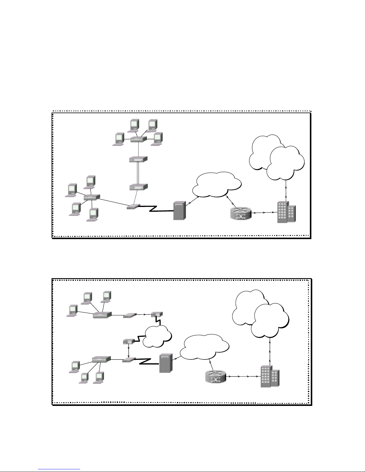
2.1 Internet Access
The WANpro support TCP/IP protocol, which the Internet uses exclusively. It is compatible with
all major IDSL DSLAM (Digital Subscriber Line Access Multiplexes) providers. A DSLAM is a
rack of IDSL line cards with data multiplexed into a backbone network interface/connection (e.g.,
T1, E1, OC3, DS3, ATM or Frame Relay). Think of it as the equivalent of a modem rack for
IDSL.
WANpro 2000i
Ethernet
DSLAM
ATM Switch
Netwo rk
Edge Router
ISP
Internet
HUB
IDSL
CSU/DSU
CSU/DSU
Ethernet
HUB
For SOHO (Small Office/Home Office) environment, your WANpro offers the NAT feature that
allows multiple users on the LAN (Local Area Network) to access the Internet concurrently for
the cost effective solution.
WANpro 2000i
Ethernet
DSLAM
ATM Switch
Network
Edge Router
ISP
Internet
HUB
WANpro 2000i
Ethernet
HUB
Modem
ISDN T/A
Modem
ISDN T/A
PSTN
ISDN
5
Page 16

2.2 LAN-to-LAN
You can use the WANpro 2000i to connect two geographically dispersed networks over the IDSL
line. Typical LAN-to-LAN applications for your WANpro are shown as follows.
WANpro 2000i
Branch Office LAN
HUB
WANpro 2000i
Corporate LAN
HUB
NTU
LTU
Lease Line
Usually WANpro 2000i act as NTU (Network Terminal Unit) when they are connected via a
Frame Relay Network. If it has connected directly via a leased line for example, the one
WANpro must act as a LTU and the other as a NTU as shown.
WANpro 2000i
Branch Office LAN
HUB
WANpro 2000i
Corporat e LAN
HUB
NTU
NTU
Frame
Relay
NTU
NTU
6
Page 17

2.3 Redundant
Either a lease line or dialup, Auto Backup function guarantee the connection to protect through
DSL line, dial up modem or ISDN T/A and ensure Internet connectivity is always available for
LAN user and LAN-based Internet servers.
WANpro 2000i
Ethernet
DSLAM
ATM Switch
Network
Edge Router
ISP
Internet
HUB
Modem
ISDN T/A
Modem
ISDN T/A
PSTN
ISDN
The Auto Backup function also can use in typical LAN-to-LAN applications.
WANpro 2000i
Branch Office LAN
HUB
WANpro 2000i
Corporate LAN
HUB
Modem
ISDN T/A
Modem
ISDN T/A
PSTN
ISDN
PPP
Frame Relay
7
Page 18

Chapter 3 Configure and Monitor Via Front Panel
This Chapter describes the physical features of the WANpro and how to make the cable
connections.
This chapter contains the following sections:
3.1 Front Panel Structure
3.2 Front Panel LEDs Indicators
3.3 Rear Panel Structure
3.4 Front Panel Operation
3.4.1 Keypad and Cursor Control
3.4.2 LCD Menu Tree
3.4.3 The Description of the LCD Configuration
8
Page 19
3.1 Front Panel S tructure
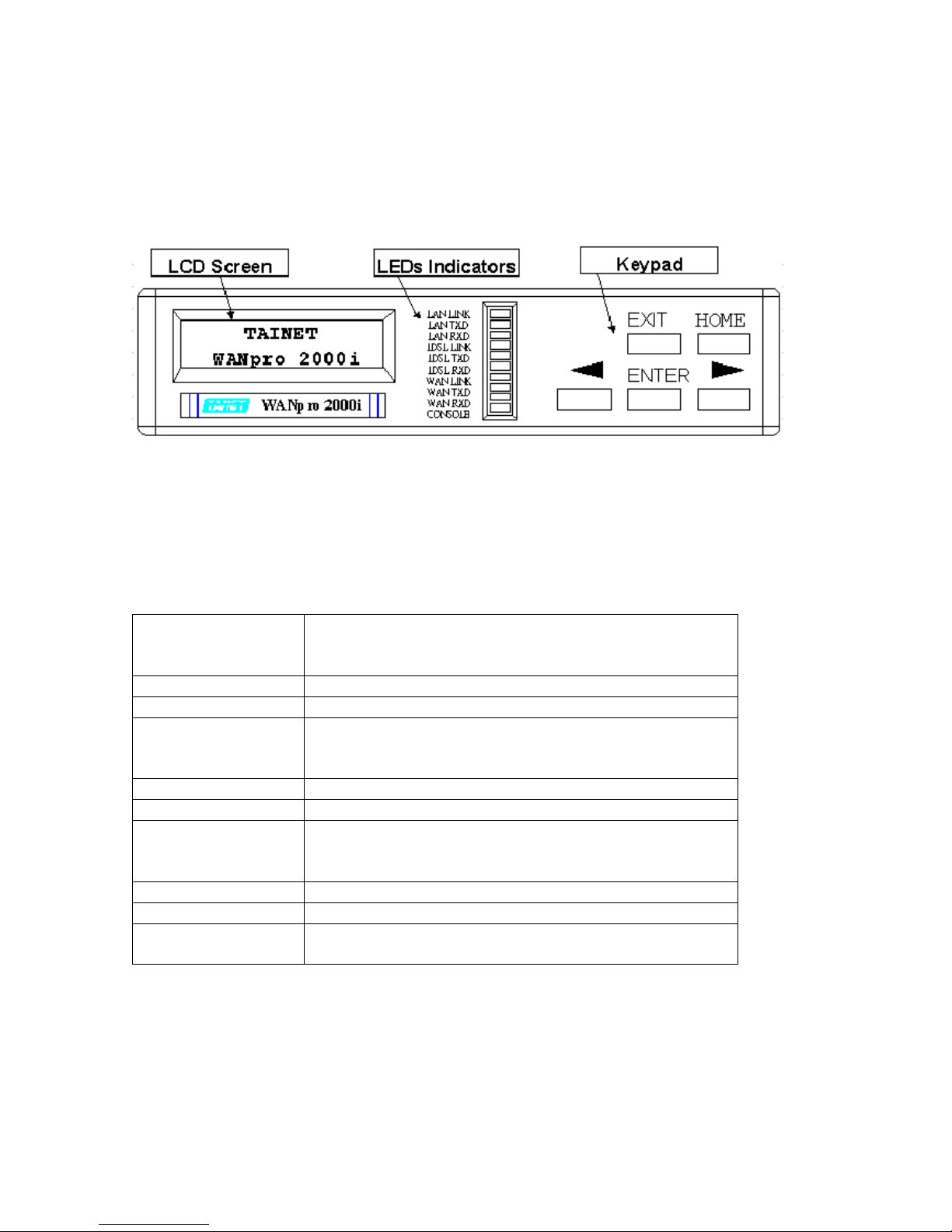
The front panel of the WANpro 2000i contains LCD Screen, LEDs Signal Indicators and
Keypads. The whole figure of the WANpro 2000i front panel could be found in the Figure 3.1A.
Figure 3.1A Front Panel of the Tainet’s WANpro 2000i
3.2 Front Panel LEDs Indicators
The LED indicators on the front panel indicate the operational status of the WANpro 2000i. The
descriptions of LED functions are shown in the Table 3-1.
LAN LINK
A steady on LAN LINK LED indicates the LAN port is up,
while an off LAN LINK LED indicates the LAN port is not
ready or malfunction.
LAN TXD
LAN port data transmits indicator.
LAN RXD
LAN port data receives indicator.
IDSL LINK
A steady on IDSL LINK LED indicates the IDSL port is
connected successfully, while the LED is off when the link is
down.
IDSL TXD
IDSL port data transmits indicator.
IDSL RXD
IDSL port data receives indicator.
WAN LINK
A steady on WAN LINK LED indicates the WAN port
PPP/FR link is up, while the LED is off when the PPP/FR
link is down.
WAN TXD
WAN port data transmits indicator.
WAN RXD
WAN port data receives indicator.
CONSOLE
A steady on CONSLOE LED port indicates the physical link
to the terminal or PC is up, otherwise the LED is off.
Table 3-1 LEDs definition
9
Page 20
3.3 Rear Panel Struct ure
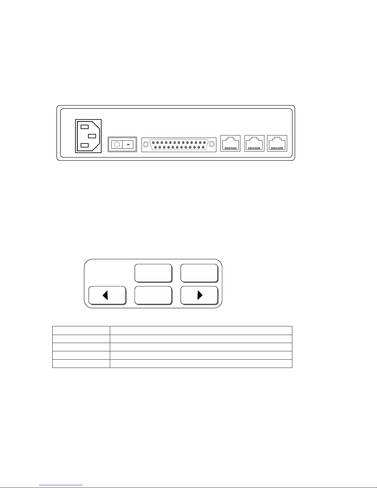
The Rear panel of the WANpro 2000i includes power, switch, and some interface ports for the
purposes of the network connection. The whole figure of the WANpro 2000i Rear panel could
be found in the Figure 3.1B.
AC INPUT
POWER SW
WAN
Console LAN IDSL
Figure 3.1B Rear Panel of the Tainet’s WANpro 2000i
3.4 Front Panel Operation
3.4.1 Keypad and Cursor Contr ol
- Keypad of the WANpro 2000i
- Cursor Control
EXIT
HOME
ENTER
EXIT
Back to the previous layer.
ENTER
Enter to the next layer. Select the parameter or move the cursor.
$ Change the parameter or to browse the selection menus.
% Change the parameter or to browse the selection menus.
HOME
Back and exit to the main menu.
10
Page 21
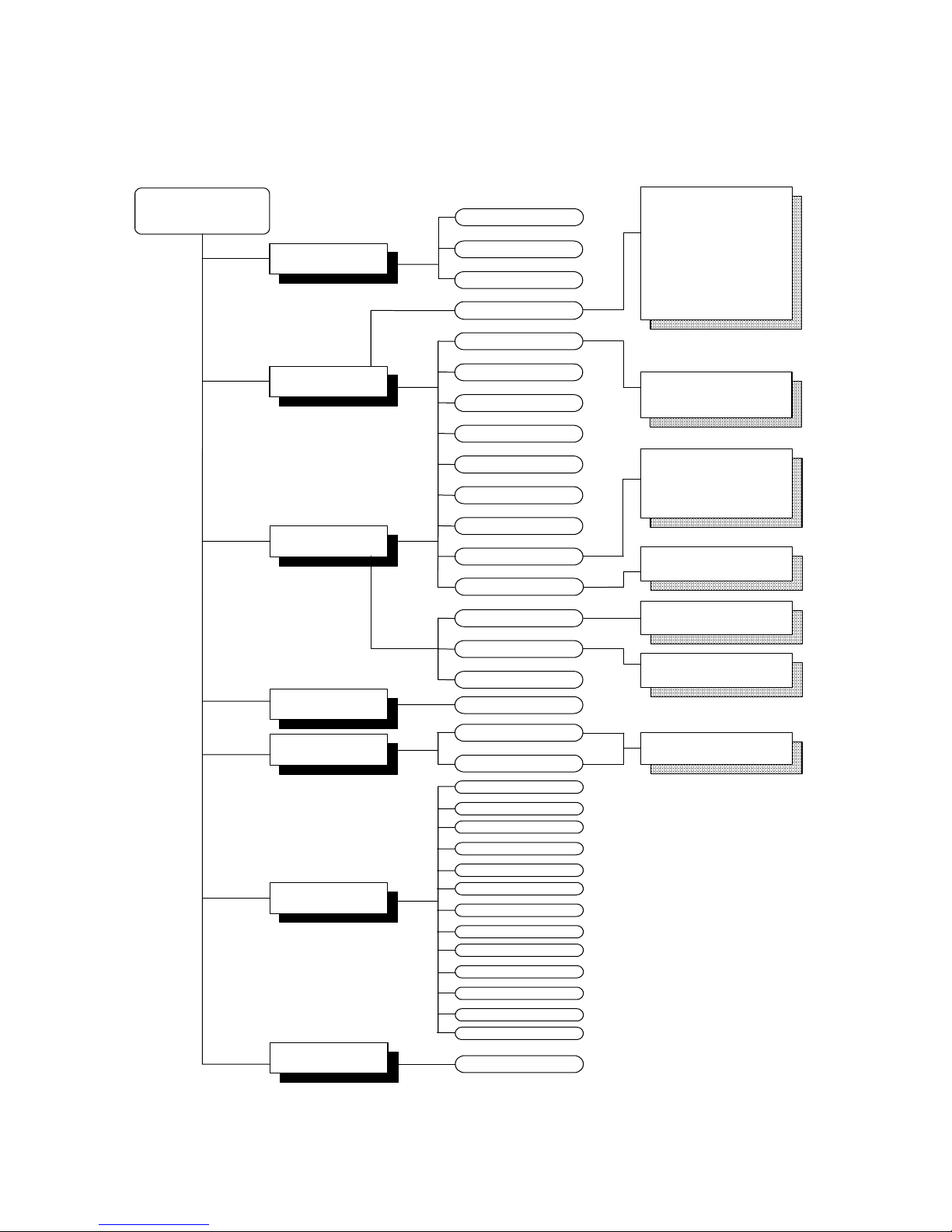
3.4.2 LCD Menu Tree
WANpro 2000i
MAIN MENU
LAN Setup
WAN Setup
IP Ne tma s k
MAC Address
WAN port Spee d <P P P>
Lo c a l IP < P P P>
IP Ne tMa s k < P P P>
Remote IP<PPP>
Local IP <FR >
IP Ne tMa s k < F R>
Re m ote IP < F R >
IDSL Setup
IDSL NTU Mode
IDSL Line Speed
IDSL TEST Loop
De f ault Ga te w ay
Warm Start
Restore Default
Protocol Select
Routing Table
Mon itor
Device Control
LMI ty p e < F R>
& PPP
& Frame Relay
& Sync - External
& Async - 115200
& Async - 38400
& Async - 19200
& Async - 9600
& Async - 4800
& Async - 2400
& Async - 1200
& No LMI
& ANSI T1.617
& ITU-T Q.933
& FR.Forum LMI
& Enter to confirm
& 64K
& 128K
& NTU
& LTU
& 0 (Default)
& Between 16 ~ 991
LAN Rx P ackets
LAN Tx Packets
LAN R x E rrors
WA N Rx Packets
WAN Tx Packets
WAN Rx Errors
IDSL Rx Packets
NAT
IDSL T x P a c k e ts
IDSL Rx Errors
DHCP Server
SNMP Agent
IP F ilte r
Diagonsis
Ping
DLCI number <FR>
IP Add re s s
Figure 3.3 LCD Menu Tree
11
Page 22

3.4.3 The Description of the LCD Configuration
LAN Setup
IP Address
The IP address is a unique 4-byte (32-bit) numeric value used to
identify a network and a local host on the network. Each IP address
consists of four sets of decimal numbers separated by the period (e.g.
192.72.243.1).
Each address is composed of two parts: a network part and a host part.
The network part identifies the unique subnet that contains the host;
the host part identifies the actual host device.
IP NetMask
The IP address netmask (also 32 bits, written in dotted decimal
notation) is used in conjunction with an IP address to specify which
b
its of the address make up t he network part and whic h the host part.
A one (1) in a mask bit location means the corresponding bit in the IP
address is part of the network value; a zero (0) means the
corresponding bit is part of the host value.
WAN Setup & IDSL Setup
WAN port Speed <PPP>
Selected the WAN port speed and data format when the WAN Protocol
is in PPP mode, in Frame Relay mode the WAN port Speed is operate
as "Sync - External".
Protocol Select
WANpro 2000i supports PPP and Frame Relay, This parameter
identifies which protocol of WAN and IDSL port is used, Frame Relay
mode can only be work at alternative WAN or IDSL but not both.
Local IP <PPP>
This parameter identifies the IP address for local WAN or IDSL port
when the protocol is selected PPP.
IP NetMask <PPP>
The IP netmask for WAN and IDSL when protocol is selected PPP.
Remote IP <PPP>
This parameter identifies the IP address for the WAN or IDSL port on a
remote router or IDSL router when the protocol is selected PPP.
Local IP <FR>
This parameter identifies the IP address for local WAN or IDSL port
when the protocol is selected Frame Relay.
IP NetMask <FR>
The IP netmask for WAN and IDSL when protocol is selected Frame
Relay.
Remote IP <FR>
This parameter identifies the IP address for the WAN or IDSL port on a
remote router or IDSL router when the protocol is selected Frame
Relay.
LMI type <FR>
A management protocol called LMI (Local Management Interface)
provides information about the status of PVC-to-network access
devices. It defines management frames fo r monitoring the integrity of a
link and whether a link is active or not.( Carrier provide)
DLCI number <FR>
The specific DLCI (Data Link Connection Identifier) for each PVC,
which is a path, number of a portion of the PVC (the DLCI changes for
each hop through the network), not the address of the destination. It is
a logical identifier with local significance only. Identifiers can range
from 16 to 991.
IDSL NTU Mode
Selected NTU or LTU for IDSL connection mode.
IDSL Line Speed
Selected the data rate for the IDSL connection. 64K or 128K
IDSL Test Loop
The IDSL loop diagnosis. Digital loop (DL)
12
Page 23

Routing Table
Default Gateway
In this field, enter the IP of the remote node that is the gateway for the
static route.
Device Control
Warm Start
Use this field to reload the parameter, this is require when a ny va lue
in LAN Setup, WAN Setup and IDSL Setup has been modified.
Restore Default
This field
will restart the system and restore the factory
default parameters.
Monitor
LAN Rx Packets
The number of received packets from LAN port.
LAN Tx Packets
The number of transfer packets from LAN port.
LAN Rx Errors
The number of packets that received from the LAN port with specific
errors. (CRC e rror, frame error, missed pac ket, unknown or
unsupported protocol, etc.)
WAN Rx Packets
The number of received packets from WAN port.
WAN Tx Packets
The number of transferred packets from WAN port.
WAN Rx Errors
The number of packets that received from the WAN port with specific
errors. (CRC e rror, frame error, missed pac ket, unknown or
unsupported protocol, etc.)
IDSL Rx Packets
The number of received packets from IDSL port.
IDSL T x Pack ets
The number of transferred packets from IDSL port.
IDSL Rx Errors
The number of packets that received from the IDSL port with specific
errors. (CRC e rror, frame error, missed pac ket, unknown or
unsupported protocol, etc.)
DHCP Server
This field identifies the DHCP Server function has enab led or disabled.
SNMP Agent
This field identifies SNMP Agent function has enabled or disabled
IP Filter
This field identifies IP Filter function has enabled or disabled.
NAT
This field identifies NAT function has enabled or disabled.
Diagnosis
Ping
In this field, enter the IP address you wish to ping, “ . “ shows device
has success received the responds from destination IP, “ ! “ shows fail.
13
Page 24

NOTICE:
Remember to warm start your WANpro if you have changed the setting of any parameters under
LAN Setup, WAN setup and IDSL setup.
Each sub-menu contains the individual selectable items. Some of the sub-menu trees might be
changed and come after later version. User could download the updated software through
Tainet’s Internet Web site.
http://www.tainet.net/tech/upgrade_fam.htm
14
Page 25

Chapter 4 Installation & Initial Setup
This chapter helps you to understand an organization of TCS (Terminal Configuration System)
and connecting of the console port.
This chapter contains the following sections:
4.1 Configuring the WANpro from a PC.
4.2 Power on your WANpro
4.3 Navigation the TCS Interface
4.4 Change the System Password.
4.5 Organization of TCS menu tree
4.5.1 Main Menu
4.5.2 Configuration Menu
4.5.3 Monitoring menu
4.5.4 Device Control
4.5.5 Diagnosis Menu
15
Page 26

4.1 Configuring the WANpro from a PC.
If you are configuring your router from a PC (not a dumb terminal), you need a type of
communications software called terminal emulation software. The PC uses this software to send
commands to your WANpro. Table 2-1 lists some common names for this software, based on the
type of PC you are using.
PC Operation System Software
Windows 95,98,ME or NT HyperTerm (included with Windows software)
Windows 3.1 Terminal (included with Windows software)
Macintosh ProComm, VersaTerm (supplied separately)
You can use the terminal emulation to change settings for the type of device that is connected to
the PC, in this case a WANpro, configure the software to the following settings, so that your PC
can communication with your WANpro:
! 19200 baud
! 8 data bits
! No parity
! 1 stop bit
! No flow control
After the WANpro has been successfully connected to your network, you can make future
changes to configuration through telnet application.
PC COM port
PC
W A Npro 2000 i
RJ-45 to RS 232
Console port
NOTICE:
You can access TCS (Terminal Configuration System) through a Telnet connection, when you
have your WANpro LAN IP setup, to setup of LAN please refer to
Chapter 6.
16
Page 27

4.2 Power on your WANpro
Before start, you should have connected the console port, the IDSL line, the Ethernet port and the
power port to the appropriate device or lines. You can now apply power to the WANpro by
turning the switch on.
Step 1. Initial Screen
When you power on your WANpro, it performs several seconds to internal tests, after it ready,
screen will shows “Press [ENTER KEY] return to menu.”, you can now press [ENTER] to the
login screen.
!!! Welcome to Access TAINET WANpro 2000i !!!
Please Enter Password :
ž`
Step 2. Entering Password
The login screen appears prompting you to enter the password.
For the first login, enter the default password root. As you type the password, the screen displays
a ( * ) for each character you type.
Please note that if there is no activity for longer than 10 minutes after you login, your WANpro
will automatically log you out and will display a initial screen message “Press [ENTER KEY]
return to menu.”, press [ENTER] to bring up the login screen again.
After you enter the password, the TCS displays the Main Menu as shown below.
MAIN TAINET WANpro 2000i Version 3.00
================================================================================
[Configuration] Monitoring Device Control Diagnosis
System Interface Routing Table Security
ENTER:select TAB:next '<':left '>':right ESC:previous menu
17
Page 28
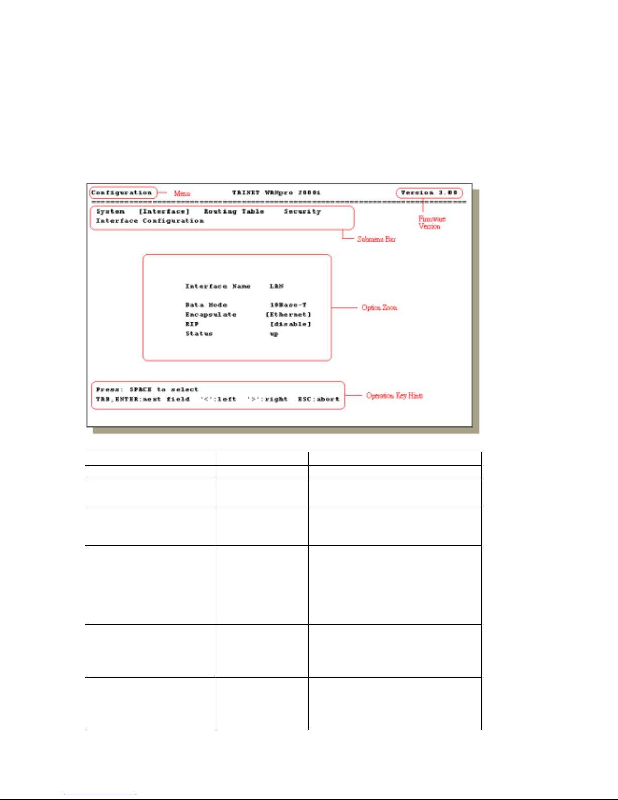
4.3 Navigation the TCS Interface
The TCS (Terminal Configuration System) is the interface that you use to configure your
WANpro.
Several operations that you should be familiar with before you attempt to modify the
configuration.
Operation Key Description
Move down to sub-menu [ENTER] To access in to a submenu.
Move up to previous menu [ESC] Press the [ESC] key to move back to
the previous menu.
Move the Cursor [<],[>],[TAB] Use [<] or [>] to move cursor left
and right or up and down, press
[TAB] to move cursor sequence.
Enter information Fill in, or press
[SPACE BAR] to
toggle.
You need to fill in two types of
fields. The First requires you to type
in the appropriate information. The
second allows you to cycle through
the available choices by pressing the
[SPACE BAR].
Save your Configuration [ENTER] Save your configuration by selecting
“YES” at the pop up “Confirm?”
message. In most cases it will take
you to the previous menu.
Exit the TCS [ESC] To exit the TCS interface, press
[ESC] at the Main Menu prompt and
pop up message “Logout” select
“YES”.
18
Page 29

4.4 Change the System Password.
You should change the password for protect your WANpro to prevent unauthorized user.
The passwords are separate to two-part “Console” and “Telnet”.
To change the System Password, enter to the Configuration menu and selected Security, and
there are two submenus under Security selected System security.
Configuration TAINET WANpro 2000i Version 3.00
================================================================================
System Interface Routing Table [Security]
Security Configuration
System Security
Console Password [root ]
Telnet [enable ]
Front Panel [enable ]
Press: ASCII, SPACE, BS, DEL
TAB,ENTER:next field '<':left '>':right ESC:abort
Step 1. Enter your new Console password (up to 10 characters), and press [ENTER]
The cursor will now move down to “Telnet” selection.
Step 2. At Telnet selection press [SPACE BAR] to enable or disable this field, to change the
Telnet username and password please select enable, if you don’t want to active the Telnet
connection then select disable.
Step 3. Enable or disable the front panel control, select disable to lock the front panel and will
not able to configure by the front panel.
Step 4. After you have change the password properly the confirm menu will pop-up, select
“YES” for confirmation. If you have change any parameter in this menu, the TCS will require
you to restart the WANpro to make the new setting effective.
19
Page 30

4.5 Organization of TCS menu tree
The TCS (Terminal Configuration System) is an user friendly configure interface, to use TCS
you can configuring and monitoring the WANpro for the advanced management.
The following diagram will help you easy to understand the TCS Organization menu.
4.5.1 Main Menu
WANpro 2000i
Configuration
Diagnosis
Device Co n trol
Monitoring
There are four categories in Main Menu:
Configuration:
This menu includes all configuration of IDSL, WAN and LAN, and some advance management.
The detail setting of this menu will be discussed at later chapters.
Monitoring:
Use monitoring menu to view system situation, interface statistics and routing table.
Device Control:
The device control menu allows you to restore the default parameter or warm start your WANpro
to load the current parameters.
Diagnosis:
In the diagnosis menu you can use ICMP ping echo to diagnosis your network.
20
Page 31

4.5.2 Configuration Menu
Configuration
System
Interface
Security
Routing Table
System:
System
SNMP Agent
DHCP Server
System Function
Fixed leases address map
You can active the DHCP server and SNMP agent in this menu.
Interface:
Interface
RIP
Encapsulate
LAN
Data mode
WAN
IDSL
Sync
Async
RIP
Encapsulate
PPP
Frame Relay
DLCI Parameter
Encapsulate
NTU mode
RIP
Data rate
Test loop
PPP
21
Page 32

There are three interface include in this menu, LAN, WAN and IDSL, in here you allow to
configure the PPP and Frame Relay encapsulation with WAN and IDSL serial interface and
Ethernet setup of LAN interface.
Routing Table:
You can add the default route and static routes in this option.
Configuration TAINET WANpro 2000i Version 3.00
================================================================================
System Interface [Routing Table] Security
Routing Table Configuration
Destination NetMask Nexthop Metric
1 192.168.0.0 255.255.255.0 10.0.0.1 1
2 172.16.1.0 255.255.0.0 10.0.0.2 1
3 0.0.0.0 0.0.0.0 0.0.0.0 0
4 0.0.0.0 0.0.0.0 0.0.0.0 0
5 0.0.0.0 0.0.0.0 0.0.0.0 0
6 0.0.0.0 0.0.0.0 0.0.0.0 0
7 0.0.0.0 0.0.0.0 0.0.0.0 0
8 0.0.0.0 0.0.0.0 0.0.0.0 0
9 0.0.0.0 0.0.0.0 0.0.0.0 0
10 0.0.0.0 0.0.0.0 0.0.0.0 0
11 0.0.0.0 0.0.0.0 0.0.0.0 0
12 0.0.0.0 0.0.0.0 0.0.0.0 0
TAB:next item ENTER:edit item '<':page up '>':page down ESC:abort
Security:
Security
System Security
Traffic Security
Telnet
WAN IDSL
NAT
IP Filter
Static NAT
Proxy Port List
Outgoing Filter
Incoming Filter
This field allows you to change the access password, and also you can configure the IP filter
which IP incoming and outgoing via WAN or IDSL interface in here.
22
Page 33

4.5.3 Monitoring menu
Monitoring
System
System
Interface Routing Table
ARP Table DHCP T abl e
Statistics
All
LAN
WAN
IDSL
Status
Address
System:
Monitoring TAINET WANpro 2000i Version 3.00
================================================================================
[System] Interface Routing Table ARP Table DHCP Table Statistics
View System Function
System Function
DHCP Server disable
SNMP Agent disable
System Security
Telnet enable
Front Panel enable
Traffic Security
Which Port WAN
NAT disable
IP Filter disable
Reflash Displey [yes]
Press: SPACE to select
TAB,ENTER:next field '<':left '>':right ESC:abort
In this field, you can easy to view the currently states of system and security function.
23
Page 34

Interface:
Monitoring TAINET WANpro 2000i Version 3.00
================================================================================
System [Interface] Routing Table ARP Table DHCP Table Statistics
View Interface Status
Iface Link Encapsulate RIP S-Ver R-Ver
1 LAN up Ethernet disable ----- ----2 WAN down PPP disable ----- ----3 IDSL down PPP Passive RIP-1 RIP-1&2
Monitoring TAINET WANpro 2000i Version 3.00
================================================================================
System [Interface] Routing Table ARP Table DHCP Table Statistics
View Interface Status
Iface Link Local NetMask Remote
1 LAN up 172.16.15.14 255.255.240.0 172.16.0.0
2 WAN down 0.0.0.0 0.0.0.0 0.0.0.0
3 IDSL down 0.0.0.0 0.0.0.0 0.0.0.0
There are 2 options under this field, Status and Address.
In Status menu you can monitor the LINK status of the encapsulation to corresponding interface.
Address menu shows the IP address, subnet mask and remote IP address of each interface
presently using.
Routing Table:
Monitoring TAINET WANpro 2000i Version 3.00
================================================================================
System Interface [Routing Table] ARP Table DHCP Table Statistics
View Routing Table
Destination NetMask Nexthop Iface Type Mtr
1 0.0.0.0 0.0.0.0 172.16.0.254 LAN US 1
2 127.0.0.1 255.255.255.255 127.0.0.1 LPBK UI 0
3 172.16.0.0 255.255.240.0 172.16.15.14 LAN UI 0
4 192.72.243.0 255.255.255.0 192.72.243.1 WAN UR 1
SPACE:refresh page '<':page up '>':page down ESC:abort
The Routing table shows all the routing information of your WANpro, include Static Routes, RIP
v1 and RIP v2.
The next table will describe the fields.
24
Page 35

Field Description
Destination It specifies the IP network address of the final destination. If
"0.0.0.0" appears in the field, this entry specifies the "Default
Gateway" of route information.
NetMask It represents the IP netmask of the destination IP address.
NextHop It represents the IP address of the next router for transmission of
the IP datagram to the destination network segment.
Iface Identify the IP routing to the corresponding interface
Type First character (Status)
U: The route is valid (up) and in use.
D: The route is invalid (down) and has a metric of 16 (RIP infinity)
Second character (Source)
I: The route is a direct connection
R: the route was established from RIP information.
S: The route is a static route.
Mtr The metric represents the cost of transmission for routing
purposes.
ARP Table:
Monitoring TAINET WANpro 2000i Version 3.00
================================================================================
System Interface Routing Table [ARP Table] DHCP Table Statistics
View ARP Table
Iface Encapsulate IP-Address Physical-Address Type Status
1 LAN Ethernet 172.16.5.41 0080C8469A5F Dynamic Active
2 LAN Ethernet 172.16.0.254 080020B0B86A Dynamic Active
SPACE:refresh page '<':page up '>':page down ESC:abort
The ARP table lists the LAN MAC addresses, which were learned by the WANpro. The WANpro
learns a device MAC address when IP traffic is generated between the router and other devices.
25
Page 36

DHCP Table:
Monitoring TAINET WANpro 2000 Version 3.00
================================================================================
System Interface Routing Table ARP Table [DHCP Table] Statistics
View the Dynamic leases of DHCP
IP Address Ethernet Address Lease Time Remaining Lease Time
1 172.16.5.97 0080C8490738 648 1200
2 172.16.5.98 0050BA1D2BE5 919 1200
3 172.16.5.99 0080C888BAF4 652 1200
4 172.16.5.100 0080C88AA02B 800 1200
5 172.16.5.102 0080C88FF9B7 735 1200
SPACE:refresh page '<':page up '>':page down ESC:abort
The DHCP table shows you the IP lease situation, you can view the remaining time for the IP
address which been dynamic and static leased, also shows the corresponding MAC address and
IP assigned lease time.
Statistics:
Monitoring TAINET WANpro 2000 Version 3.00
================================================================================
System Interface Routing Table ARP Table DHCP Table [Statistics]
View Interface Statistics
Interface Name LAN
Tx Octets 1373680
Tx Packets 5664
Tx Broadcast Packets 2994
Tx Discarded Packets 0
Rx Octets 43968968
Rx Packets 1606
Rx Broadcast Packets 395481
Rx Discarded Packets 4
Rx Unknow Protocols 145471
Reflash Displey [yes]
Press: SPACE to select
TAB,ENTER:next field '<':left '>':right ESC:abort
The Statistics provides a snapshot view of interface packets flow count, you can select the
specify interface to view detail static rather then select ALL.
26
Page 37

4.5.4 Device Control
Device Control
Warm Start Restore Default
There are two options under device control menu:
Warm Start:
This command will causes the system restart and reloads the parameter, it also interpreter the
WAN and IDSL connection.
Restore Default:
This command will restart the system and restore the factory default parameters.
27
Page 38

4.5.5 Diagnosis Menu
Diagnosis
Ping Information
There are two submenus include in diagnosis menu, Ping and Information.
Ping:
Diagnosis TAINET WANpro 2000i Version 3.00
================================================================================
[Ping] Information
IP Connectivity
Host Reachability
Target IP Address [172.16.5.41 ]
Datagram Size [100 ]
Timeout in Seconds [2 ]
PING 172.16.5.41 with 100 bytes of data
Reply from 172.16.5.41: bytes=100 time<10ms
Reply from 172.16.5.41: bytes=100 time<10ms
Reply from 172.16.5.41: bytes=100 time<10ms
Reply from 172.16.5.41: bytes=100 time<10ms
Reply from 172.16.5.41: bytes=100 time<10ms
Press any key to continue!
When you encounter an IP routing problem such as not being able to communicate with a remote
host or if you simply want to verify connectivity you can use the ping command to help you
diagnose it.
Information:
This option shows the version of BOOT ROM and FLASH firmware.
28
Page 39

Chapter 5 IDSL & WAN configuration
This chapter helps you setup your IDSL and WAN link of WANpro with it PPP and Frame Relay
connection.
This chapter contains the following sections:
5.1 IDSL & WAN Interface
5.2 Setting up the IDSL PPP link
5.3 Setting up the WAN PPP link
5.4 Frame Relay Setup
5.4.1 Encapsulation
5.4.2 DLCI
5.4.3 LMI
5.4.4 Manipulation Frame Relay via WAN or IDSL
29
Page 40

5.1 IDSL & WAN Interface
You can tread your WANpro 2000i as two serial ports device, which are IDSL interface and
WAN interface. Depend on the network scheme you can elasticity to use both or either one.
The IDSL port operates full duplex over twisted pair, 2-wire unconditioned lines, and operates at
data rates 64 kbps or 128 kbps.
The WAN port acts as DTE interface therefore it must collocate with CSU/DSU or modem, and
it support following digital interface:
! V.24/RS-232 (Data rates up to 128 kbps at Sync mode, 115200 bps at Async. mode)
! V.35 (Sync. mode data rates up to 1 Mbps)
! RS-530 (Sync. mode data rates up to 1 Mbps)
! X.21 (Sync. mode data rates up to 1 Mbps)
30
Page 41

5.2 Setting up the IDSL PPP link
RFC 1662 defines PPP over HDLC (High-level Data Link Control). HDLC is a bit-oriented,
(mean that the data is monitored bit by bit) link layer protocol for the transmission of data over
synchronous networks. Transmissions consist of binary data without any special control codes.
Information is the frame contains control and response commands, however. HDLC supports
full-duplex transmission, in which data is transmitted in two directions at the same time,
resulting in higher throughput. HDLC is suitable for point-to-point and multipoint (multidrop or
ne-to-many) connections. o
Configuration TAINET WANpro 2000i Version 3.00
================================================================================
System [Interface] Routing Table Security
Interface Configurati on
Interface Name IDSL
NTU Mode [NT]
Encapsulate [PPP ]
RIP [disable]
Status down
Press: SPACE to select
TAB,ENTER:next field '<':l eft '>':right ESC:abort
At IDSL interface menu, you allow to configure the IDSL data rate and assign the PPP
encapsulation.
The IDSL LINK LED on front panel can help you to diagnosis the IDSL physical link is success
connect, but this do not guarantee the PPP protocol is up, you can check it from interface static
at Monitoring menu to make sure the PPP link is UP. If the IDSL LINK LED is bright and the
interface static shows IDSL link is down, then you have focus on the setting of PPP
encapsulation. The following are the example of IDSL PPP setting.
31
Page 42
WANpro 2000i WANpro 2000i
PC
PC
PC
PC
PC
PC
Site A
10.0.0.1/30
Site B
10.0.0.2/30
Ethernet
Ethernet
Pair Copper Wire
IDSL-NT Mode
IDSL-LT Mode
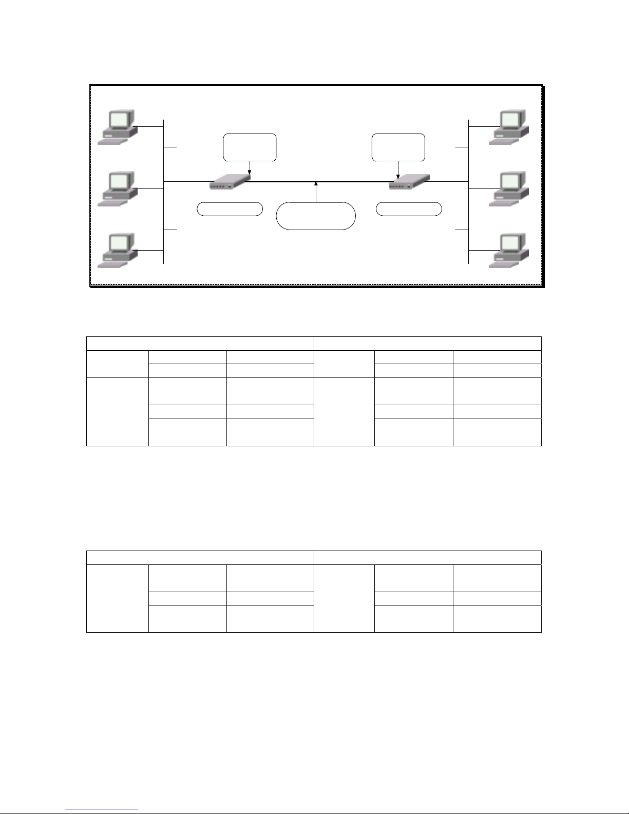
The above diagram shows the IDSL PPP link, configuration of your WANpro 2000i could be like
follow.
Site A (10.0.0.1/30) Site B (10.0.0.2/30)
Data Rate 128 k Data Rate 128 k NTU mode
<NT>
Test Loop Disable
NTU mode
<LT>
Test Loop Disable
Local IP
address
10.0.0.1 Local IP
address
10.0.0.2
NetMask 255.255.255.252 NetMask 255.255.255.252
Encapsulate
<PPP>
Remote IP
address
0.0.0.0
Encapsulate
<PPP>
Remote IP
address
0.0.0.0
You should configure the IDSL NTU (Network Terminal Unit) in to the proper mode, IDSL data
rate should be the same at both site.
Test Loop function will be discuss at Chapter 9.
The standard PPP encapsulate can be setup as above table or you can assign the IP to the remote
site.
Site A (Local) Site B (Remote)
Local IP
address
10.0.0.1 Local IP
address
0.0.0.0
NetMask 255.255.255.252 NetMask 0.0.0.0
Encapsulate
<PPP>
Remote IP
address
10.0.0.2
Encapsulate
<PPP>
Remote IP
address
0.0.0.0
NOTICE:
The IP shown this section are examples. You should substitute the IP values shown with values
that are appropriate for your network.
32
Page 43

5.3 Setting up the WAN PPP link
Configuration TAINET WANpro 2000i Version 3.00
================================================================================
System [Interface] Routing Table Security
Interface Configurati on
Interface Name WAN
Data Mode [Sync ]
Encapsulate [PPP ]
RIP [disable]
Status down
Press: SPACE to select
TAB,ENTER:next field '<':l eft '>':right ESC:abort
At WAN Interface you allow to configure the WAN port data mode and PPP encapsulate.
The WAN LINK LED on front panel can help you to diagnosis the WAN port PPP link is success
connect and PPP protocol is up, you can also check it from interface static at Monitoring menu
to make sure the PPP link is UP.
If you have setup the physical WAN port connect and configure the PPP encapsulate at proper
static, but WAN LINK LED is off and the interface static shows WAN link is down, then you
have focus on the both setting of PPP encapsulation and physical connect. When WAN LINK
LED is bright mean “Serial is up and protocol is up”. The following are the example of WAN
PPP setting.
33
Page 44

WANpro 2000i WANpro 2000i
PC
PC
PC
PC
PC
PC
Site A
10.0.0.1/30
Site B
10.0.0.2/30
Ethernet
Ethernet
CSU/DSU
or
Modem
CSU/DSU
or
Modem
The above diagram is the WAN PPP link, configuration of your WANpro 2000i could be like
follow.
Site A (10.0.0.1/30) Site B (10.0.0.2/30)
Data mode Sync Data mode Sync
Local IP
address
10.0.0.1 Local IP
address
10.0.0.2
NetMask 255.255.255.252 NetMask 255.255.255.252
Encapsulate
<PPP>
Remote IP
address
0.0.0.0
Encapsulate
<PPP>
Remote IP
address
0.0.0.0
Configure the Data mode to Sync (Synchronous – External clock), the WANpro will follow the
data rate from the DCE device such as Modem or CSU/DSU.
The standard PPP encapsulate can be setup as above table or you can assign the IP to the remote
site.
Site A (Local) Site B (Remote)
Local IP
address
10.0.0.1 Local IP
address
0.0.0.0
NetMask 255.255.255.252 NetMask 0.0.0.0
Encapsulate
<PPP>
Remote IP
address
10.0.0.2
Encapsulate
<PPP>
Remote IP
address
0.0.0.0
NOTICE:
The IP shown this section are examples. You should substitute the IP values shown with values
that are appropriate for your network.
34
Page 45

5.4 Frame Relay Setup
Configuring Frame Relay on a WANpro includes the mapping of IP addresses to DLCIs and
telling the router which virtual circuits are connected.
Configuration TAINET WANpro 2000i Version 3.00
================================================================================
System [Interface] Routing Table Security
Interface Configurati on
+----------------Encapsulate----------------+
| |
| Interface Name WAN |
| Encapsulate Frame Relay |
| |
| Local IP Address [0.0.0.0 ] |
| NetMask [0.0.0.0 ] |
| LMI Type [ANSI T1.617 Annex D ] |
| DLCI parameter [enable] |
| |
+-------------------------------------------+
Press: '0' - '9', '.', SPACE, BS, DEL
TAB,ENTER:next field '<':l eft '>':right ESC:abort
5.4.1 Encapsulation
The WANpro support IP over Frame Relay encapsulation describes in RFC 1490, which is the
method for carrying network interconnect traffic over a frame relay backbone. It also describes a
simple fragmentation procedure for carrying large frames over a frame relay network with a
smaller MTU.
5.4.2 DLCI
The carrier gives you a specific DLCI (Data Link Connection Identifier) for each PVC that is a
path number of a portion of the PVC (the DLCI changes for each hop through the network), not
the address of the destination. It is a logical identifier with local significance only. Identifiers can
range from 16 to 991.
5.4.3 LMI
The carrier also gives you the LMI (Local Management Interface) type, The LMI is a set of
enhancements to the basic Frame Relay specification. LMI includes support for keepalives, a
multicast mechanism, global addressing, and a status mechanism. Your WANpro support three
LMI standards: ANSI T1.617 Annex D, CCITT Q.933a Annex A and LMI by Frame Relay Forum.
35
Page 46

5.4.4 Manipulation Frame Relay via WAN or IDSL
Your WANpro 2000i allow only one serial port to act Frame Relay encapsulation, either WAN
port or IDSL port, but not both.
Configuration TAINET WANpro 2000i Version 3.00
================================================================================
System [Interface] Routing Table Security
Interface Configurati on
+------------------------DLCI parameter-------------------------+
| |
| DLCI Local IP NetMask Remote IP |
| |
| 1 [110 ] 10.0.0.1 255.255.255.0 [168.0.2.17 ] |
| 2 0 10.0.0.1 255.255.255.0 0.0.0.0 |
| 3 0 10.0.0.1 255.255.255.0 0.0.0.0 |
| 4 0 10.0.0.1 255.255.255.0 0.0.0.0 |
| 5 0 10.0.0.1 255.255.255.0 0.0.0.0 |
| 6 0 10.0.0.1 255.255.255.0 0.0.0.0 |
| 7 0 10.0.0.1 255.255.255.0 0.0.0.0 |
| 8 0 10.0.0.1 255.255.255.0 0.0.0.0 |
| |
+---------------------------------------------------------------+
Press: '0' - '9', '.', SPACE, BS, DEL <Must locate inside the network>
TAB,ENTER:next field '<':l eft '>':right ESC:abort
DLCI parameter table allows you to configure up to 8 remote IP nodes. The Local IP and
Netmask in DLCI table will automatically match to an encapsulate which you assign.
Information of DLCI parameter table should match to the Frame Relay switch.
36
Page 47

Frame Relay
Network
WANpro
2000i
PC
PC
Frame Relay
Switch
Frame Relay
Switch
IDSL device
IDSL device
WANpro
2000i
PC PC
Manipulation Frame Relay
via IDSL Interface
Frame Relay
Switch
Frame Relay
Switch
Frame Relay
Network
WANpro
2000i
PC
PC
Frame Relay
Switch
Frame Relay
Switch
WANpro
2000i
PC PC
Manipulation Frame Relay
via WAN Interface
CSU/DSU
or
Modem
CSU/DSU
or
Modem
CSU/DSU
or
Modem
CSU/DSU
or
Modem
Frame Relay
Switch
Frame Relay
Switch
37
Page 48

CHAPTER 6 LAN and Routing Access Configuration
This chapter shows you how to configure the LAN as well as the WAN of your WANpro for
Internet access.
This chapter contains the following sections:
6.1 Ethernet Setup
6.2 RIP Setup
6.3 DHCP Setup
6.4 Configuring Static Routes & Default Routes
6.4.1 Configuring Static Routing Table
6.4.2 Configuring Default Gateway
38
Page 49

6.1 Ethernet Setup
You can have TCP/IP setup for your WANpro at LAN Interface menu.
Configuration TAINET WANpro 2000i Version 2.99t
================================================================================
System [Interface] Routing Table Security
Interface Configuration
+-------------Encapsulate--------------+
| |
| Interface Name LAN |
| Encapsulate Ethernet |
| Ethernet MAC 0090BB000022 |
| |
| Local IP Address [192.168.0.254 ] |
| NetMask [255.255.255.0 ] |
| |
+--------------------------------------+
Press: '0' - '9', '.', SPACE, BS, DEL
TAB,ENTER:next field '<':left '>':right ESC:abort
Under LAN encapsulate option, you enable to configure LAN interface with an IP address and a
subnet mask, the IP address should be your router Ethernet IP address.
39
Page 50

6.2 RIP Setup
Routing Information Protocol (RIP) is a distance vector protocol for use intra-domain (on the
interior of a gateway). There are actually two versions of RIP in the TCP/IP protocol suite.
Version 1 is the original. Version 2 is the updated version. Version 2 is used almost exclusively
because of its enhanced capabilities.
Your WANpro support both RIP-1 and RIP-2, RIP-1 is universally supported; but RIP-2 carries
more information. RIP-1 is probably adequate for most networks, unless you have an unusual
network topology.
Configuration can be performed on a per-interface basis. You can enable or disable RIP for each
interface, WAN, IDSL and LAN. The following table describes the RIP option of your WANpro.
Configuration TAINET WANpro 2000i Version 3.00
================================================================================
System [Interface] Routing Table Security
Interface Configurati on
+--------------RIP---------------+
| |
| Interface Name IDSL |
| |
| Mode [Passive] |
In | Send_Version [RIP-1] |
| Recive_Version [RIP-1&2] |
NT | Default Route [0 ] |
En | Hotzon [SPLIT ] |
RI | Next Hop Advertise [no ] |
St | Sub Accept [yes] |
| Sub Advertise [yes] |
| |
+--------------------------------+
Press: SPACE to select
TAB,ENTER:next field '<':l eft '>':right ESC:abort
NOTICE:
WANpro sends both of RIP-1 and RIP-2 in broadcasting mode, if you have third party router
connected with WANpro at same network segment or remote node, please configure the third
party router RIP-2 to broadcasting mode, therefore the third party router can receive the RIP-2
form WANpro, because WANpro do not support RIP-2 with multicasting mode.
Generally if RIP-2 operates at multicasting mode, it does not listen to the RIP-2 broadcasting and
so will not receive the RIP-2 packets. However, if one router uses broadcasting, then all routers
on your network must use broadcasting.
40
Page 51

Mode:
The interface can execute passive or active RIP. When executing passive RIP, the interface
revises its routing table based on the routing update information it receive, but does not advertise
self-routing information to other routers. When configured for active RIP at specifies interface
acts as a full router; it not only listens for updates but also advertises it routing table information
every 30 seconds.
* Passive
Enable Passive RIP. (Receive RIP packet only)
Active
Enable Active RIP. (Receive and send RIP table)
Send_Version:
Controls the version(s) of RIP advertisements. Available with active RIP only.
OFF
Disable the version(s) of RIP advertisement.
* RIP-1
Enable the RIP version 1 advertisement.
RIP-2
Enable the RIP version 2 advertisement.
Reveive_Version:
Controls the version(s) of RIP updates that are accepted.
OFF
Disable the version(s) of RIP upgrades that are accepted.
RIP-1
Enable the version of RIP-1 upgrades that are accepted.
RIP-2
Enable the version of RIP-2 upgrades that are accepted.
* RIP-1&2
Enable the versions of RIP-1 and RIP-2 upgrades that are accepted.
Default Route:
Controls and sets the WANpro to advertise itself as the default router.
* 0
Disable
1~15
Enable and specifies the number of hops to a destination.
Horizon:
Controls the spilt horizon and poison reverse mechanisms. Available with active RIP only.
* SPLIT
Split horizon
POISON
Poison reverse
Next Hop Advertise:
Specifies whether or not the next hop value is included in the RIP version 2 advertisements.
Available with active RIP only.
YES
Next hop value will not be included in the RIP version 2 advertisements.
* NO
Next hop value will not be included in the RIP version 2 advertisements.
Sub Accept:
Controls whether or not subnet routes are accepted in updates.
* YES
Subnet routes will be accepted in updates.
NO
Subnet routes will not be accepted in updates.
Sub Advertise:
Controls whether or not the RIP advertises subnets. Available with active RIP only.
* YES
RIP advertises subnets.
NO
RIP does not advertise subnets.
NOTICE:
The " * " mark means the default value of RIP parameter.
41
Page 52

6.3 DHCP Setup
Dynamic Host Configuration Protocol (DHCP) is used for the dynamic distribution of IP address
to client machines, allow the individual clients (workstations) to obtain the TCP/I P configuration
t start-up from centralized DHCP server. a
The WANpro has built-in DHCP server capability, to enable DHCP function can be find under
Configuration System menu. In here you can configure the DHCP server setting for IP default
gateway, DNS server and WINS server.
Enable Fixed Leases Address Map allow you to assign up to 8 permanent IP leases to clients by
elling the client's NIC (Network Interface Card) Ethernet Address (MAC address). t
=
[
Configuration TAINET WANpro 2000i Version 3.00
===============================================================================
System] Interface Routing Table Security
System Configuration
+------------------DHCP Server------------------+
| |
| Default Lease Time (Secs) [38400 ] |
| Gateway [172.16.11.11 ] |
| DNS Server [172.16.0.1 ] |
| WINS Server [0.0.0.0 ] |
| IP Address Pool |
| Range from [172.16.8.10 ] |
| to [172.16.8.254 ] |
| Fixed Leases Address Map [disable] |
| |
+-----------------------------------------------+
Press: '0' - '9', '.', SPACE, BS, DEL
TAB,ENTER:next field '<':left '>':right ESC:abort
Configuration TAINET WANpro 2000i Version 3.00
================================================================================
[System] Interface Routing Table Security
System Configuration
+--------Fixed Leases Address Map---------+
+- | | -+
| | IP Address Ethernet Address | |
| | | |
| | 1 172.16.5.41 0080C8469A5F | |
| | 2 0.0.0.0 000000000000 | |
| | 3 0.0.0.0 000000000000 | |
| | 4 0.0.0.0 000000000000 | |
| | 5 0.0.0.0 000000000000 | |
| | 6 0.0.0.0 000000000000 | |
| | 7 0.0.0.0 000000000000 | |
| | 8 0.0.0.0 000000000000 | |
+- | | -+
+-----------------------------------------+
42
Page 53

Field Description
Default Lease Time (Secs) This field specifies an IP address lease time for clients.
It is base on seconds and the default value is 38400
(10 hrs).
Gateway
DNS Server
WINS Server
Those fields specify an IP default gateway, DNS server
and WINS server to Windows 95/98, Windows NT and
other systems that support the DHCP client.
The default value for Gateway is the LAN IP address of
this device.
IP address pool Setups the dynamic IP scope in this field, IP will be
assigned to client machines in this range pool.
Fixed Leases Address Map Assign the fixed IP to special clients or other server
machines, e.g. server for mail, FTP, telnet, web, etc. that
you may have to knowing their Ethernet address.
NOTICE:
There aren't any configurations about Netmask for clients, because WANpro will use the
Netmask value from configuration item of the LAN encapsulation.
The fix IP address should not be include inside the IP address pool range of dynamic leases, else
there will be an IP conflict in your network.
The Default Lease Time suggestion:
If you have some hosts move in and move out frequently, a short lease time is preferred.
If hosts in your network are stable, a long lease time can also reduce the packet exchange
between server & clients.
43
Page 54
6.4 Configuring Static Routes & Default Routes
Routes between network segments sometimes have to be added manually. There are several
advantages that static routes have over dynamic routes. One advantage is that there is less
overhead for the router, since it doesn't have to perform calculations on the fly and send out
router updates.
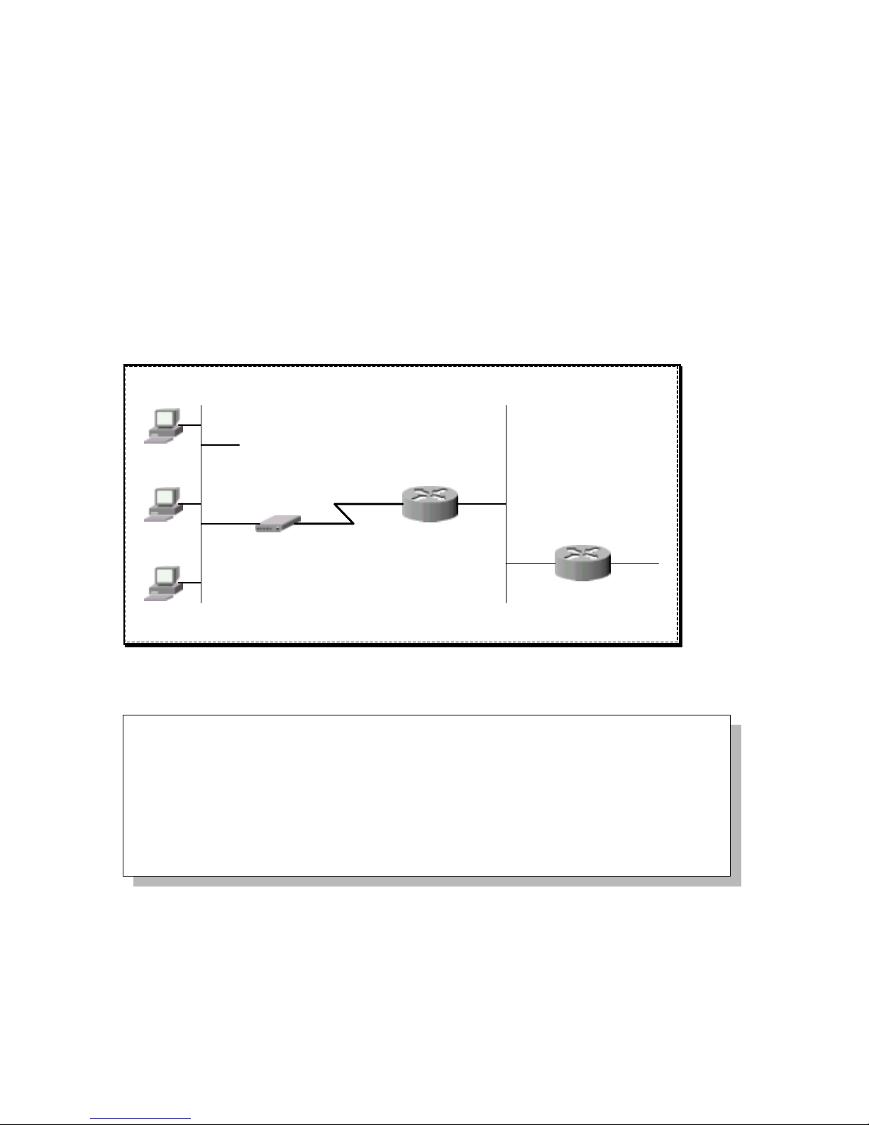
Each remote note specifies only the network to which the gateway is directly connected, and the
WANpro has no knowledge of the networks beyond. For instance, the WANpro knows about
network B in the following diagram through remote node Router 1. However, the WANpro is
unable to route a packet to network C because it doesn't know that there is a route through
remote node Router 1 (via Router 2). The static routes are for you to tell the WANpro about the
networks beyond the remote nodes.
WANpro 2000i
PC
PC
PC
Router 1
Router 2
Network A
Networ k B Networ k C
Configuring static routes and default gateway can be finding in Configuration Routing Table
menu.
Configuration TAINET WANpro 2000i Version 3.00
================================================================================
System Interface [Routing Table] Security
Routing Table Configuration
+----------Routing Table-----------+
|<Static Routing> Default Gateway |
+----------------------------------+
44
Page 55

6.4.1 Configuring Static Routing Table
Configuration TAINET WANpro 2000i Version 3.00
================================================================================
System Interface [Routing Table] Security
Routing Table Configuration
Destination NetMask Nexthop Metric
1 0.0.0.0 0.0.0.0 0.0.0.0 0
2 0.0.0.0 0.0.0.0 0.0.0.0 0
3 0.0.0.0 0.0.0.0 0.0.0.0 0
4 0.0.0.0 0.0.0.0 0.0.0.0 0
5 0.0.0.0 0.0.0.0 0.0.0.0 0
6 0.0.0.0 0.0.0.0 0.0.0.0 0
7 0.0.0.0 0.0.0.0 0.0.0.0 0
8 0.0.0.0 0.0.0.0 0.0.0.0 0
9 0.0.0.0 0.0.0.0 0.0.0.0 0
10 0.0.0.0 0.0.0.0 0.0.0.0 0
11 0.0.0.0 0.0.0.0 0.0.0.0 0
12 0.0.0.0 0.0.0.0 0.0.0.0 0
TAB:next item ENTER:edit item '<':page up '>':page down ESC:abort
Static routes are those route that you define in the WANpro manually. Static routes exist
permanently unless you change them. You may use static routes to establish fixed connections
and to augment the RIP routing table.
The maximum capacity of WANpro routing index list can number up to 20.
Field Description
Destination This parameter specifies the IP network address of the final destination.
Routing is always based on network number. If you need to specify a
route to a single host, use a subnet mask of 255.255.255.255 in the
subnet mask field to force the network number to be identical to the host
ID.
NetMask Enter the subnet mask for this destination.
NextHop Enter the IP address of the next hop (router). This is an immediate
neifhbor of your WANpro that will forward the packet to the destination.
On the LAN, the next hop must be a router on the same segment as your
WANpro; over WAN, the next hop must be the IP address of one of the
remote nodes.
Metric The metric represents the cost of transmission for routing purposes. IP
routing uses hop count as the measurement of cost, which a minimum of
1 for directly connected networks. Enter a number that approximates the
cost for this link. The number need not be precise, but it must be
between 1 and 15. In practice, 2 or 3 is usually a good number.
45
Page 56

6.4.2 Configuring Default Gateway
Imagine in large network and internetworks every router cannot know the exact route to every
other router. This is where the default gateway (sometimes call default route) is useful. The
default route specifies where to send non-local packets. The router will know what to do with it.
If the next router doesn't know the necessary route, it sends the packet to its own default gatewa y,
and this process continues on until the destination network is reached. Configuration of default
gateway is performed under Configuration Routing Table.
Configuration TAINET WANpro 2000i Version 3.00
================================================================================
System Interface [Routing Table] Security
Routing Table Configuration
Default Gateway [172.16.0.254 ]
46
Page 57

Chapter 7 NAT & IP Filter
This chapter shows you how NAT work with your WANpro and discusses the function of IP
filter.
This chapter contains the following sections:
7.1 NAT Setting
7.2 IP Filter Setting
47
Page 58

7.1 NAT Setting
We can classify IP addresses in two kinds: local (private) and global (public). Local IP addresses
cannot be used on the Internet and are mostly used on Local Area Networks (LANs). Public
addresses are valid on the Internet and must be properly registered so information can be sent to
them. Configure of NAT can be find under the Configuration Security - Traffic Security menu.
Configuration TAINET WANpro 2000i Version 3.01
================================================================================
System Interface Routing Table [Security]
Security Configuration
+-----------------------------NAT------------------------------+
| |
| Static NAT (Network Address Translation) [disable] |
| |
| NAPT (Network Address Port Translation) |
| Public IP [0.0.0.0 ] |
| NetMask [0.0.0.0 ] |
| Proxy Port List [disable] |
| |
+--------------------------------------------------------------+
Press: SPACE to select
TAB,ENTER:next field '<':left '>':right ESC:abort
Figure 7-1 NAT Configuration Menu
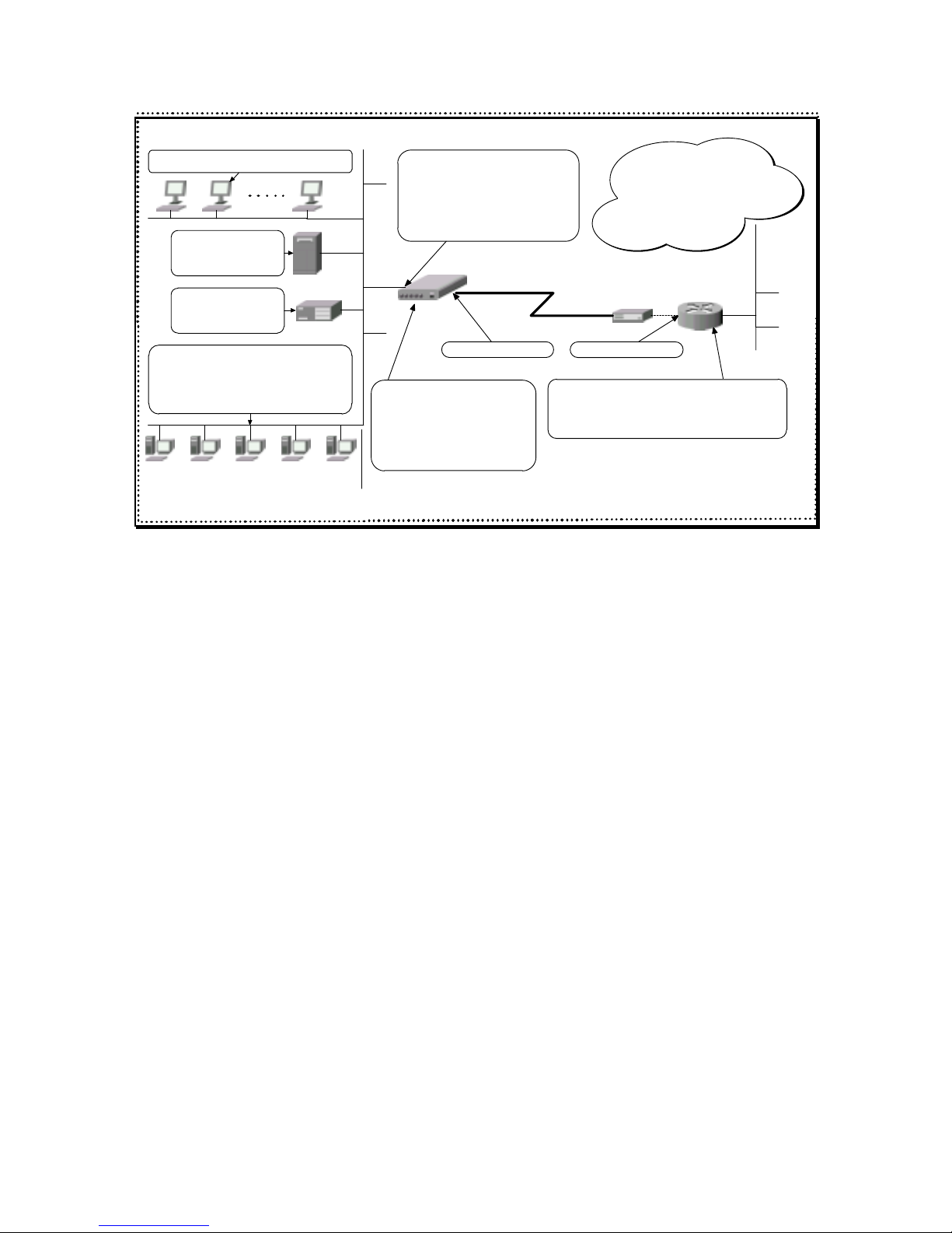
NAT, described in RFC 3022, allows local IP addresses on the LAN to be converted into global
IP addresses on the Internet.
WANpro use NAPT (Network Address Port Translation) device maps ALL the local IP addresses
into a SINGLE global IP address that assigned by an ISP. The PAT will perform a mapping
between local port addresses and global port addresses from a pool of available port addresses.
The advantage of this scheme, in addition to those mentioned above, is cost savings; only
one ISP account and IP address is required.
In addition, the PAT scheme provides privacy since the internal LAN is unavailable to hosts on
the Internet; all they can see is the single IP address interface provided by the PAT device.
48
Page 59
WANpro 2000i
Internet
192.168. 1.1 (LAN I/F)
Private IP use in
this LAN segment is
192.168.1.0/27
192.168. 1.2 ~ 192.168. 1.23
FTP Serv er
192.168.1.24
Web Server
192.168.1.25
168.192.0.2 ~ 168.192.0.6
IP Pass- Through matc h to
192.168. 1.26 ~ 192.168. 1.30
ISP Router
IDSL Device
IDSL PPP Link
IDSL IP : 10.0.0.2/30
Serial IP : 10.0.0.1/30
NAT enable
Public IP: 168.192.0.1
NetMask: 255 . 25 5. 2 55. 248
Proxy Port List: Enable
Static NAT: Enable
Public IP pool assign by ISP is
168.192.0.0/29
Routing Table in ISP Router
" ip route 168.192.0.0 255.255.255.248 10.0.0.2 "
LAN
Figure 7-2 Example of NAT Application
Enable Proxy Port List function you can make inside servers for different services, e.g. web or
FTP, visible to the outside users, even though NAT makes your whole inside network appear as a
single machine to the outside world. The port number and protocol identify the service, e.g. web
service is on port 80 TCP and TFTP is on port 69 UDP. The protocol supports in this feature are
TCP, UDP and ICMP.
Enable Static NAT function maintains a simple one-to-one mapping between a local and global IP
address for each host on the LAN. The main benefit of this is avoiding reconfiguration of local IP
addresses on each host.
Figure 7-2 shows you how NAT work with the public and private IP. Assume you have apply the
network segment of public IP form your ISP, that say 168.192.0.0/29, the public IP for you to use
is between 168.192.0.0 ~ 168.192.0.7, but in real you have only 5 public IP (one for router,
another two for net ID and broadcast) for your LAN but there you have total 30 computer in your
LAN include workstations and few server.
Use NAT will helps you solve this embarrassing situation, the configuring of this example are as
follow.
49
Page 60

Step 1. Selected the public IP for PAT
Choose one IP between 168.192.0.1 ~ 168.192.0.6 for PAT. The NetMask should match to the
network segment that ISP assigns to you.
+-----------------------------NAT------------------------------+
| |
| Static NAT (Network Address Translation) [enable ] |
| |
| NAPT (Network Address Port Translation) |
| Public IP [168.192.0.1 ] |
| NetMask [255.255.255.248] |
| Proxy Port List [enable ] |
| |
+--------------------------------------------------------------+
Step 2. Proxy Port List
Use this function to make a server visible to the outside world, specify the port number of the
service and the inside IP address of the server behind NAT.
Enter the protocol and port number in the field and the inside IP address of the server in the
Proxy IP.
+------------Proxy Port List------------+
| |
| Protocol Port Proxy IP |
| |
| 1 TCP 21 192.168.1.24 |
| 2 TCP 80 192.168.1.25 |
| 3 TCP 0 0.0.0.0 |
| 4 TCP 0 0.0.0.0 |
| 5 TCP 0 0.0.0.0 |
| 6 TCP 0 0.0.0.0 |
| 7 TCP 0 0.0.0.0 |
| 8 TCP 0 0.0.0.0 |
| |
+---------------------------------------+
The most often used port numbers are shown in the following table. Please refer to RFC 1700 for
further information about port numbers.
Services Port Number
FTP (File Transfer Protocol) 21
Telnet 23
SMTP (simple Mail Transfer Protocol) 25
DNS (Domain Name System) 53
HTTP (Hyper Text Transfer protocol or Web) 80
50
Page 61

Step 3. Configuring the Static NAT
Assign the remaining public IP to the workstation or server in your LAN.
+-Static NAT (Network Address Translation)--+
| |
| Public IP Private IP |
| |
| 1 168.192.0.2 192.168.1.26 |
| 2 168.192.0.3 192.168.1.27 |
| 3 168.192.0.4 192.168.1.28 |
| 4 168.192.0.5 192.168.1.29 |
| 5 168.192.0.6 192.168.1.30 |
| 6 0.0.0.0 0.0.0.0 |
| 7 0.0.0.0 0.0.0.0 |
| 8 0.0.0.0 0.0.0.0 |
| |
+-------------------------------------------+
51
Page 62

7.2 IP Filter Setting
Your WANpro uses filters to decide whether or not to allow passage of a packet. IP filters are
divided into incoming and outgoing filters, depending on the direction of the packet relative to a
serial port, WAN or IDSL alternative. To enable the IP Filter can be find under Configuration
Security - Traffic Security.
There has filter table for each incoming and outgoing filter, this allow you to configure specifies
IP traffic that are permitted to access your LAN.
Configuration TAINET WANpro 2000i Version 3.00
================================================================================
System Interface Routing Table [Security]
Security Configuration
+-------------IP Filter--------------+
| |
| Incoming Filter [Default Deny ] |
| Outgoing Filter [Default Deny ] |
| |
+------------------------------------+
You can choose the filter mode to "Default Deny" or "Default Permit", this option mode will
match to the filter table.
For example, if you have set the Incoming Filter to Default Deny then the corresponding serial
port (WAN or IDSL) will only allows IP incoming from the list of incoming filter table which
has the type of permit. The same logicality with Default Permit.
+----------------- --- --- -------Incoming Filter-------------------------------+
| |
| Type Source IP MASK Destination IP MASK Protocol Port |
| |
| 1 Permit 172.168.1.0 24 192.168.1.0 24 ALL 0 |
| 2 Deny 0.0.0.0 0 192.168.1.254 0 ALL 0 |
| 3 No 0.0.0.0 0 0.0.0.0 0 ALL 0 |
| 4 No 0.0.0.0 0 0.0.0.0 0 ALL 0 |
| 5 No 0.0.0.0 0 0.0.0.0 0 ALL 0 |
| 6 No 0.0.0.0 0 0.0.0.0 0 ALL 0 |
| 7 No 0.0.0.0 0 0.0.0.0 0 ALL 0 |
| 8 No 0.0.0.0 0 0.0.0.0 0 ALL 0 |
| |
+----------------- --- --- -----------------------------------------------------+
IP Filter table allows you configure against to the specify field. Leave the field to default "0" or
"0.0.0.0" means all include or don't care.
52
Page 63

Chapter 8 SNMP Configuration
This chapter discusses SNMP (Simple Network Management Protocol) for network management
and monitoring.
This chapter contains the following sections:
8.1 About SNMP
8.2 Configuring SNMP
53
Page 64

8.1 About SNMP
Your WANpro supports SNMP (Simple Network Management Protocol) agent functionality,
which allows a manager station to monitor the WANpro through the network.
8.2 Configuring SNMP
To enable the "SNMP Agent" can be find at Configuration System - System Function.
Configuration TAINET WANpro 2000i Version 3.00
================================================================================
[System] Interface Routing Table Security
System Configuration
+---------------------SNMP Agent----------------------+
| |
| System Contact [Keven Lin ] |
| System Name [WANpro 2000i ] |
| System Location [Taipei ] |
| |
+-----------------------------------------------------+
Press: ASCII, SPACE, BS, DEL
TAB,ENTER:next field '<':left '>':right ESC:abort
WANpro 2000i so far only provides "GET" value with SNMP, and Get Community is as default
"public", this is simply SNMP terminology for password.
54
Page 65

Chapter 9 System Maintenance
This Chapter covers the diagnostic method that help you to maintain your WANpro.
This chapter contains the following sections:
9.1 System Status
9.2 IDSL Local Loop Back
9.3 Firmware Upgrade
9.3.1 Upload Router Firmware - Uploads from DOS mode
9.3.2 Upload Router Firmware - Upload from NT 4.0 Platform
55
Page 66

9.1 System Status
System status can be monitoring under Monitoring menu, this menu arrange all system
information let comes easy to diagnosis the problem. The detail of each field please refers to
chapter 4.5.3 in this menu.
9.2 IDSL Local Loop Back
Uses IDSL local loop back to diagnosis the loop characteristic and the device.
Configuration TAINET WANpro 2000i Version 3.00
================================================================================
System [Interface] Routing Table Security
Interface Configuration
+---------NTU Mode ----------+
| |
Inte | Interface Name IDSL |
| |
NTU | Data Rate [128K] |
Enca | Test Loop [enable ] |
RIP | |
Stat +----------------------------+
Enable Local Loop Back can be find under Configuration Interface - IDSL NTU Mode, enable
this field the system will require to restart to active this action.
WANpro 2000i
IDSL Dev ice
BERT Test Equipment
LT Site
NT Site
56
Page 67

9.3 Firmware Upgrade
The firmware is the program that controls the functions of the WANpro.
Platform Upload method Description
MS_DOS Upload from DOS Support all version of WANpro 2000i.
Win95/98 N/A
WinNT 4.0 Upload from NT Support all version of WANpro 2000i. No
"Packet Drive" required.
Win2000 N/A
NOTICE:
Firmware upload won't cause the excise parameter setting lost.
9.3.1 Upload Router Firmware - Uploads from DOS mode
Flasht.exe is the tool for user to upgrade the firmware, which can be use for the following
TAINET product; CS-Jr, WANpro 2000, NMC32, NMC9000, and Router Module. This program
can only be operated at pure 16-bit MS-DOS mode.
There is another program user need to prepare before execute Flasht, which is the "Packet
Drive" for your PC Ethernet NIC (Network Interface Card), This is necessary because under
pure MS-DOS mode the Ethernet card is not yet to been active. User needs to install a drive to
make Ethernet device for PC running. The "Packet Drive" is just like to creative a layer two
communication. Different brand of Ethernet card will have different "Packet driver", usually it
will be attach in the CD or floppy disk when user buy the Ethernet card.
Files require:
Flasht.exe (TAINET Network Device flash agent tools for MS-DOS)
wr_fxxx.bin (binary firmware, upload file)
The Flash agent upgrade file can be download at
http://www.tainet.net/tech/upgrade_fam.htm
Step 1: Access to MS-DOS mode and Run Flasht
Power on your Wanpro.
Turn the PC with packet driver under MS-DOS mode.
Run flasht.exe to prepare upload firmware.
Tip: User can press Shift+F5 before Win95/98 start to access in to pure MS-DOS mode.
Step 2: Selected the firmware file to upload
Press 1 to select the file, e.g. C:\temp\wr_f213.bin
Press Enter to select and exit select menu (press ESC to reselect).
At top of screen you should see this sentence " Load File: C:\temp\rm_f213.bin " .
Step 3: Target the upgrade device
Press 2 "All Target Identification" menu.
User should see the list table of device find by the Flash program on your network.
57
Page 68

Press ESC to exit.
Product ID :
01 - WANpro 2000
02 - CS-Jr
03 - NMS9000
04 - Non-Channelize Router
05 - Channelize Router
06 - WANpro 2000i
Step 4: Upload the firmware
Press 3 "Selected Target Upload" to target the device, this menu will list the device that has been
identify in your network on setup 2.
SW-Ver shows current version of the device.
Use Ethernet Address, Product ID and SW-Ver to filter the possibility if there is more then one
target shows on the list table.
Target the device by select the number on the list, "#" shows the target has been mark for which
you wish to upgrade, you can select the target again to remark the target. Press " F " to start
uploads the firmware.
Step 5: Restart
When done, the devices will automatic restart.
58
Page 69

9.3.2 Upload Router Firmware - Upload from NT 4.0 Platform
This method is similar as the previous, only different are move the operating platform from
MS-DOS to Windows_NT_4.0. This method is for those users who feel difficult to find the
"Packet Driver" for their Ethernet Card. The same, before running the upload agent tool user
needs to add the new protocol for NT4.0 which is call "NDIS 3.0 Packet Driver v3.5", Please
following the instructions below to work out it.
Files require:
Download.exe (TAINET Network Device upload agent tools for NT4.0)
wr_fxxx.bin (binary firmware, upload file)
Oemsetup.inf (Protocol Driver for NT4.0)
Packet.sys (Protocol Driver for NT4.0)
http://www.tainet.net/tech/upgrade_fam.htm
Step 1: Access to the NT Network properties
Point to the "Network Neighborhood" icon on desktop, click the mouse right button, and then
select properties. User should see the sub-windows named "Network" popup.
Step 2: Adding new protocol driver.
Select the "Protocols" folder, press "add" and select "Have Disk" to setup the driver from the
correspond path, the path should point to where the files stored. Selected "NDIS 3.0 Packet
Driver v3.5" in the dialog and selected OK.
After all, user can find this protocol driver has been success add to the Services folder.
Step 3: Restart NT
NT will automatic request to restart the computer.
Step 4: Find the MAC address of upgrade device
After NT restart, find the Router's MAC address by manually, because this upload agent
(download.exe) did not support auto detect. There is two ways to find the MAC address of
device.
1. Using " ping " and " arp -a " command to find out the MAC address.
Eg. If the Router's LAN IP is "192.168.0.1". At command mode.
------------------------------------------------------------------------------------C:\ping 192.168.0.1
C:\arp -a
Interface: 192.168.0.254 on Interface 0x2000003
Internet Address Physical Address Type
192.168.0.1 00-06-29-38-06-b0 dynamic
------------------------------------------------------------------------------------Recorded the last 6 bits, for the above example is " 3806b0 ".
2. Open the Xstream 1300 lid, find the sticker which stick on the Router module main chip, there
should have the laster 6 digits of MAC address print on the sticker.
Recorded those 6 digits.
59
Page 70

Step 5: Start upgrade
Running Upload agent by telling then the new firmware file and destination MAC address.
Usage:download -f <file> -m <mac>
<file> Specify the binary file for download.
<mac> Specify the target MAC address.
E.g. C:\download -f c:\temp\rm_f213.bin -m 3806b0
Step 6: Restart
Restart the Device.
60
Page 71

Chapter 10 Troubleshooting
This chapter covers the potential problems you may run into and the possible remedies. After
each problem description, some instructions are provided to help you to diagnose and to solve
the problem.
This chapter contains the following sections:
10.1 Problems Starting Up the WANpro
10.2 Problem with the IDSL Interface
10.3 Problems with the LAN Interface
61
Page 72

10.1 Problems Starting Up the WANpro
Problem Corrective Action
None of the LEDs and LCD are on when you
power on the WANpro
Check the connection between the AC adapter
and the WANpro.
If the error persists, you may have a hardware
problem. In this case You should contact
technical support.
1. Check to see if the WANpro is connected to
your computer serial port.
VT 100 terminal
emulation
19200 bps
Cannot access the WANpro via the console port.
2. Check to see if the
communication
program is configured
correctly . The
communications
software should be
configured as follows:
No parity, 8 Data bits, 1
Stop bit, Flow Control
set to None.
10.2 Problem with the IDSL Interface
Problem Corrective Action
Initialization of the lease line (PVC) connection
failed.
Ensure that the cable is conneted properly from
the IDSL port to the wall jack. The IDSL Link
LED on the front panel of the WANpro should
be on. If not, check Menu 5.2 to verify that the
NTU mode of both side should not be the same,
and Data Rate should be the same as the peer,
Test Loop needs to be disable. If you still have
problems, you mayneed to verify these
variables with the telephone company and/or
ISP or the peer IDSL device or router (in a
LAN-to-LAN application).
10.3 Problems with the LAN Interface
Problem Corrective Action
Check the LAN LINK LEDs on the front panel.
The LED should be on for a port that has a
station connected. If it is off, check the cables
between your WANpro and the station.
Can't ping any station on the LAN
Verify that the IP address and the subnet mask
are consistent between the WANpro and
workstations.
62
Page 73

Chapter 11 Interface PinOut List
This chapter contains the following sections:
11.1 WAN Interface PinOut List
11.2 RS-232 adapter for Console Interface PinOut
11.3 IDSL Interface Pin Assignment
63
Page 74

11.1 WAN Interface PinOut List
SIGNAL
FUNCTION
SOURCE
V.24/RS-232
DB-25 (F)
V.35
DB-25 (F)
EIA-530
DB-25 (F)
INPUT
OUTPUT
Protective
Ground
COMMON 1 1 1 -----
Signal
Ground
COMMON 7 7 7 -----
Transmitted
Data
DTE 2
2 (TXD A)
14 (TXD B)
2 (TXD A)
14 (TXD B)
OUTPUT
Received
Data
DCE 3
3 (RXD A)
16 (RXD B)
3 (RXD A)
16 (RXD B)
INPUT
Request
To Send
DTE 4 4 4 OUTPUT
Clear
To Send
DCE 5 5 5 INPUT
Data Terminal
Ready
DTE 20 20 20 OUTPUT
Carrier
Detect
DCE 8 8 8 INPUT
Transmit
Clock
DCE 15
15 (TXC A)
12 (TXC B)
15 (TXC A)
12 (TXC B)
INPUT
Receive
Clock
DCE 18
17 (RXC A)
9 (RXC B)
17 (RXC A)
9 (RXC B)
INPUT
11.2 RS-232 adapter for Console Interface PinOut
RJ-45 (WANpro) DB-25 (PC)
Pin
Signal
Function
Pin
Signal
Function
1 PG 1 PG
2 RXD 2 TXD
3 TXD 3 RXD
4 CTS 4 RTS
5 RTS 5 CTS
6 DTR 6 DSR
7 SG 7 SG
8 DCD 8 DTR
64
Page 75

65
11.3 IDSL Interface Pin Assignment
1 2 3 4 5 6 7 8
RJ-45 Signal Function
1
2
3
4 Tip/Ring
5 Tip/Ring
6
7
8
 Loading...