

Page 1

V1.5 07008-00032 2004/03/24
TAINET
WANpro 2000
WAN ACCESS ROUTER
USER'S MANUAL
The Professional Partner
TAINET COMMUNICATION SYSTEM CORP.
Headquarters:
No. 25, Alley 15, Lane 120, Sec. 1. Nei-Hu Rd.,
Taipei 114, Taiwan, R.O.C.
TEL: 886-2-26583000
FAX: 886-2-26583232
Beijing Branch:
3F, A Building, 113 Zhi Chun Lu,
HaiDian District, Beijing, China
Zip Code: 100086
Tel: 86-10-62522081~87
Fax: 86-10-62522077
Page 2

Copyright © 1999 Tainet Communication Corporation.
All rights reserved.
Printed in Taiwan R.O.C.
Notice
This document is protected by the international copyright law. No part of this
publication may be reproduced by any means without the permission of Tainet
Communication Corporation.
TAINET is a registered trademark, and “WANpro 2000” is a trademark of
Tainet Communication Corporation.
Other product names mentioned in this manual are used for identification
purposes only and may be trademarks or trademarks of their respective
companies.
The information provided from Tainet Communication Corporation is
believed to be accurate. Any changes and enhancements to the product and to
the information thereof will be documented and issued as a new release to this
manual.
Page 3
FCC NOTICE
This equipment has been tested to comply with limits for a digital device,
pursuant to Part 15 of the FCC Rules. These limits are designed to provide
reasonable protection against harmful interference when the equipment is
operated in a commercial environment. This equipment generates, uses, and
can radiate radio frequency energy and, if not installed and used in
accordance with instruction manual, may cause harmful interference to
radio communication.
If the equipment does cause harmful interference to radio or television
devices, the user is encouraged to try to correct the interference by one or
more of the following advises:
1. Reorient or relocate the receiving antenna.
2. Increase the separation between the equipment and receiver.
3. Connect the equipment into an outlet on a circuit different from that
to which the receiver is connected.
4. Consult the dealer or an experienced radio/TV technician for help.
The FCC Rule is available from the U.S. government Printing Office,
Washington, DC 20402, Stock NO. 004-00000345-4.
The shielded RS-232 cable is to be used in order to ensure compliance with
FCC Part 15, and it is the responsibility of the user to provide and use
shielded RS-232 cable from NTU to personal computer.
We will not commit to repair this unconditional fault resulting from the user.
The warranty issue will only protect for right operations mentioned in the
manual, and extra charge for this fault might be noticed if necessary.
Any changes of modifications not expressly approved by the grantee
of this device could void the user’s authority to operate the
equipment.
Page 4

HOW TO USE THIS MANUAL
This section gives you some ideas about how to use this manual effectively.
It includes brief description of the summary chapters and the symbol used
inside the manual.
Summary Chapters
Section Description
Chapter 1 Quick Start.
Describe quick installation for Tainet’s WANpro 2000
device
Chapter 2 Introduction
General introduction to Tainet’s WANpro 2000 device
Chapter 3 Configure and Monitor Via Front Panel
Provide the procedures to setup the user interface and
using LEDs, status to monitor the device via LCD Front
Panel.
Chapter 4 Configure and Monitor Via PCs or Terminals
Provide the procedures to setup the user interface and
using LEDs, status to monitor the device via PCs or
Terminals.
Provide information to view and check the network
conditions.
Appendix A Interface Specifications & Cable Diagrams
Describe the port connectors and interface information.
Appendix B Technical Specifications
Contains physical, electrical and mechanical
specifications.
Glossary Define acronyms and terms used in this manual.
Page 5
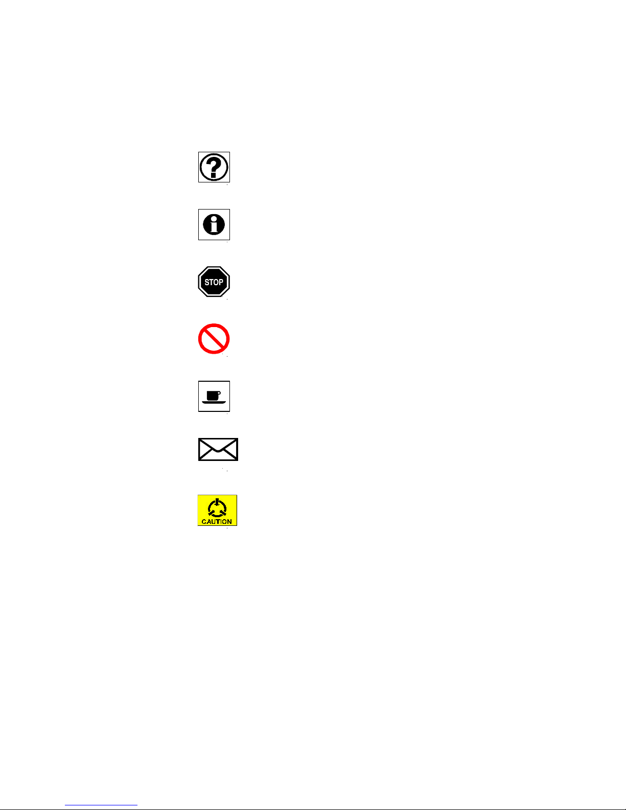
Symbols Have Been Used
There are eight types of the messaging symbols used inside the text. By the
way, users will be warned in conditions during chapters.
The questions from the section
The extra information provided for the user
Stop here to check conditions
Users are prohibit
Break time
How to contact
Warning messages
Page 6

WARRANTY AND SERVICE INFORMATION
If there is any question, contact your local sales representative,
service representative, or distributor directly for any help needed.
You might use one of the following methods:
n Via the Internet: visit our world wide web site at
http://www.tainet.net
n Via the Sales Representatives:
HQ
No. 25, Alley 15, Lane 120, Sec. 1 Nei-Hu Rd., Taipei, Taiwan
TEL: (886) 2-2658-3000 FAX: (886) 2-2658-3232
E-mail: #[email protected]
URL: http://www.tainet.net
Moscow Branch
111024, Shosse Entuziastov, Building 14, Room 425, Moscow, Russia
TEL: (7) 095-7850-377 FAX: (7) 095-7850-378
URL: http://www.tainet.ru
Beijing Branch
3F, A Building, 113 Zhi Chun Lu, HaiDian District , Beijng , China
Zip Code: 100086
TEL: Tel: 86-10-62522081~87 FAX: 86-10-62522077
E-mail: [email protected]
URL: http://www.tainet.com.cn
Guangzhou Representative Office
TEL: (86) 20-8758-5976, 8759-0695 FAX: (86) 20-8758-5976
Shanghai Representative Office
TEL: (86) 21-6487-6066, 6427-0809 FAX: (86) 21-6487-5825
Chengdu Representative Office
TEL: (86) 28-522-4651, 522-4652 FAX: (86) 28-522-4652
Page 7

CONTENTS
Copyright
FCC Notice
How to Use This Manual
CHAPTER 1 QUICK START...................................................................1
1.1 How to Begin – the first step for the user..................................... 2
1.1.1 Unpacking .........................................................................2
1.1.2 Connecting Power to the Device........................................3
1.1.3 Connecting to the Network ................................................3
1.2 How to Operate and Setup Internet Applications..........................4
1.3 How to Operate and Setup Intranet Applications..........................6
CHAPTER 2 INTRODUCTION............................................................... 1
2.1 Tainet’s WANpro 2000................................................................2
2.1.1 Features............................................................................. 2
2.1.2 Specifications .................................................................... 2
2.2 Applications................................................................................4
CHAPTER 3 Configure and Monitor Via Front Panel............................... 1
3.1 Font Panel ...................................................................................2
3.2 Identify LEDs Light Status..........................................................2
3.3 Rear Panel................................................................................... 3
3.4 Front Panel Operation..................................................................3
CHAPTER 4 Configure and Monitor Via PCs or Terminals ......................1
4.1 Connect WANpro 2000 to PCs or Terminals................................2
4.2 The ‘Configuration’ .....................................................................4
4.3 Main Menu:.................................................................................6
4.4 Configuration Menu ....................................................................6
4.4.1. System...............................................................................7
4.4.2. PPP.................................................................................. 10
Page 8

4.4.3 FR....................................................................................11
4.4.4. RIP_Setting .....................................................................12
4.4.5. Routing_Table .................................................................14
4.4.6. Security ...........................................................................17
4.4.7 NAT................................................................................. 20
4.4.8 Filter................................................................................23
4.4.9 DHCP..............................................................................26
4.5 Monitor Menu ...........................................................................28
4.5.1 Current_Configuration.....................................................28
4.5.2 Routing_Table .................................................................29
4.5.3 ARP_Table ...................................................................... 31
4.5.4 Statistics ..........................................................................32
4.5.5 NAT_Buffer.....................................................................35
4.5.6 DHCP..............................................................................36
4.6 Device_Control .........................................................................37
4.6.1 Warm_Start......................................................................37
4.6.2 Restore_Default...............................................................37
4.7 Diagnosis Menu......................................................................... 38
4.7.1 Ping.................................................................................38
Appendix A Interface Specifications & Cable Diagrams............................ 1
A1. WAN Interface PinOut List (Female Connectors)........................2
A2. Console Cable RJ-45 – DB-25 Connector PinOut........................3
A3. LAN Interface RJ-45 Connector PinOut......................................3
Appendix B Technical Specifications........................................................ 1
B1 LAN Interface .............................................................................2
B2. WAN Interface ............................................................................2
B3. CONSOLE Interface ...................................................................2
B4. Power..........................................................................................2
Glossary...................................................................................................1
Page 9

FIGURES
Figure 1.1A Front Panel of the Tainet’s WANpro 2000 ....................................... 1-2
Figure 1.1B Rear Panel of the Tainet’s WANpro 2000 ........................................ 1-2
Figure 1.2 The Internet Connection over PPP................................................... 1-4
Figure 1.3 The Internet Connection over Frame Relay...................................... 1-5
Figure 1.4 The Intranet Connection over PPP................................................... 1-6
Figure 2.1 Applications to xDSL Series Modem............................................... 2-4
Figure 3.1A Front Panel of the Tainet’s WANpro 2000 ....................................... 3-2
Figure 3.1B Rear Panel of the Tainet’s WANpro 2000 ........................................ 3-3
Figure 3.2 General Initialized Procedures of the WANpro 2000 Device........... 3-4
Figure 3.3 LCD Menu Tree.............................................................................. 3-6
Figure 4.1 The Console Port Connection to PCs or Terminals .......................... 4-3
Figure 4.2 Main Menu Tree.............................................................................. 4-5
Figure 4.3 Example of WANpro 2000 application............................................ 4-7
Page 10

Page 11

QUICK START
CHAPTER 1
QUICK START
Overview
1.1 How to Begin – the first step for the user
1.1.1 Unpacking
1.1.2 Connecting Power to the Device
1.1.3 Connecting to the Network
1.2 How to Operate and Setup Internet Applications
1.3 How to Operate and Setup Intranet Applications
1-1
Page 12
QUICK START
1.1 How to Begin – the first step for the user
1.1.1 Unpacking
To check the components that you might have,
Accessory Provided
ü Tainet WANpro 2000 user's manual
ü One digital interface (refer to DTE interface options)
ü Power cord
ü RJ-11 cable (S.A only)
ü RJ-11 box (S.A only)
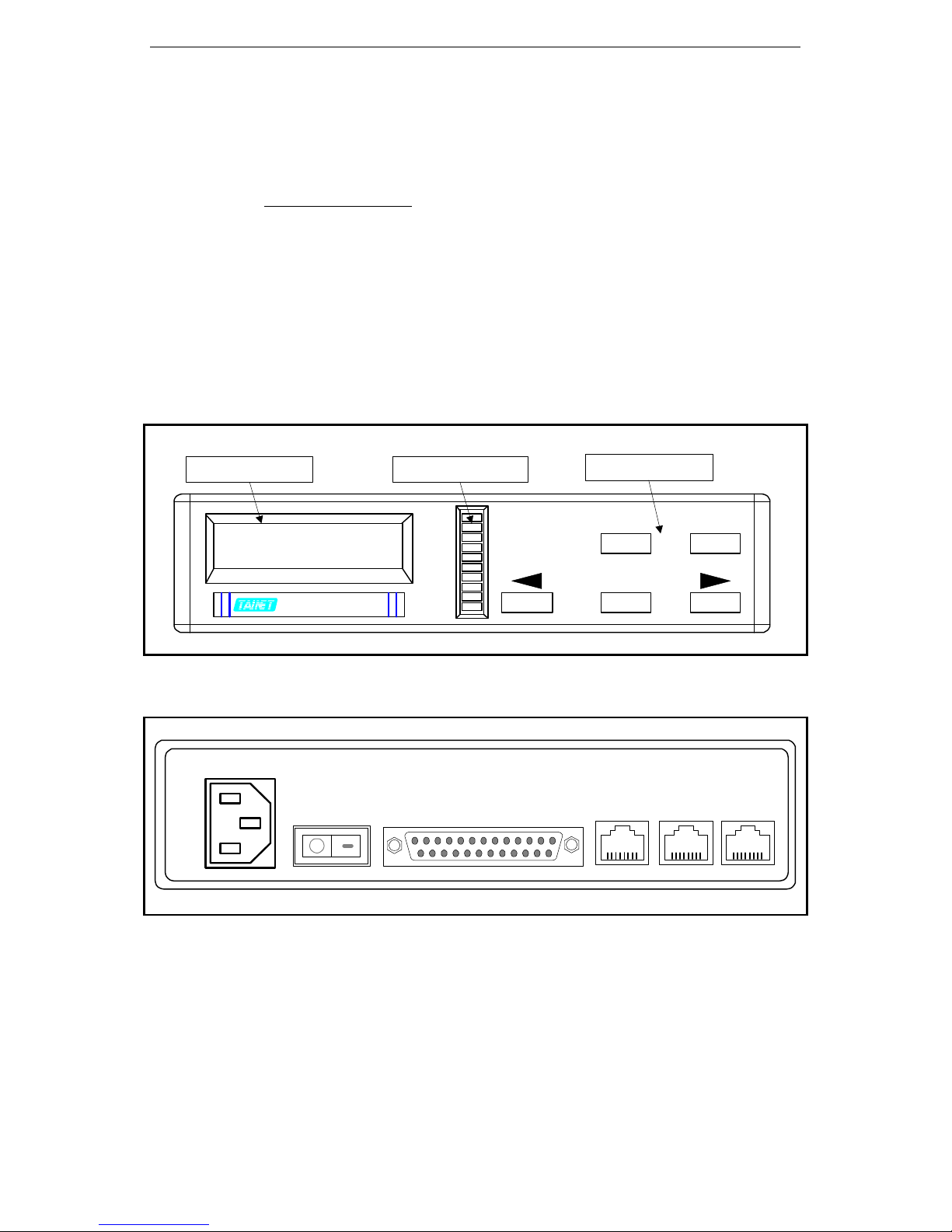
The front panel of the WANpro 2000 device contains LCD Screen, LEDs
Signal Indicators and Keypad. The whole figure of the WANpro 2000 Front
panel could be found in the Figure 1.1A.
LCD Screen LEDs Indicators
LAN
TAINET
WANpro 2000
WANpro 2000
Figure 1.1A Front Panel of the Tainet’s WANpro 2000
AC INPUT
POWER
LANT
LANR
RTS
CTS
TXD
RXD
LINK
CSR
CST
WAN
Keypad
EXIT VO/DA
ENTER
Console LAN ISDN
Figure 1.1B Rear Panel of the Tainet’s WANpro 2000
1-2
Page 13
QUICK START
case to avoid touching internal components.
the earth to protect your system.
User’s optional interface modules are depending on their applied network
interface. The optional modules of the WAN interface (see Figure 1.1B)
might include V.24, V.35 RS-530 and X.21. The Console port is used to
monitor and operate the device via PCs or Terminals.
User should not change any modules without
permission from the manufacturer.
The inspection of any damages from shipment includes bending or loosing
hardware components, and broken connectors.
To prevent electrostatic discharge (ESD)
damage, user should avoid not open up the
1.1.2 Connecting Power to the Device
The AC power requirement of the WANpro 2000 device is 115/230 VAC
auto-range input. Before you switch on the device, be sure that you plug the
power cord.
It is strongly recommended that you should
also screw a Protective Ground (PG) wire to
1.1.3 Connecting to the Network
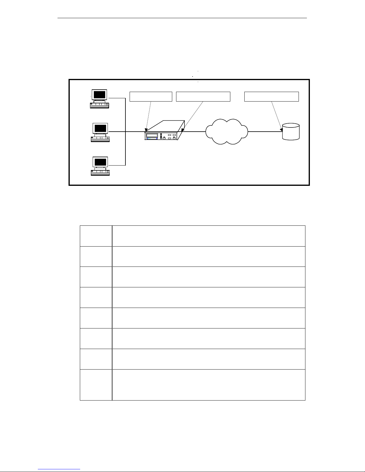
There are several optional interfaces and connectors such as WAN port
(RS-232 Cable), LAN port (RJ-45), ISDN port – unavailable (RJ-45). The
basic connection of devices could be shown in Figure 1.2.
The WANpro 2000 device is working like a Bridge or Gateway DTEs to
communicate remotely through the RJ-45 for LAN port to Ethernet Network
and RS-232 cable to DCEs for WAN port.
For details of using modules, you need to
contact your local sales representative.
PCs or Terminals could be used to setup system configuration or monitor
system status via Console Port. The DCE could be a Modems, ISDNs or
xDSL Series devices and so on that connect to the WANpro 2000 device
through WAN Port (25 DB).
1-3
Page 14
QUICK START
Step 2
1.2 How to Operate and Setup Internet Applications
Ethernet LAN
192.72.240.252192.10.25.1 192.72.240.253
Host
LAN
EXIT VO/DA
LANT
TAINET
LANR
RTS
CTS
WANpro 2000
TXD
RXD
ENTER
LINK
CSR
WANpro 2000
CST
Host
WANpro 2000
Host
Figure 1.2 The Internet Connection over PPP
An Example of the Setup Procedures via front panel
Step 1:
Step 3:
Step 4:
Under LAN Setup menu:
:
Under LAN Setup menu:
Under WAN Setup menu:
Under PPP Setup menu:
IP Address = 192.10.25.1
IP NetMask = 255.255.255.0
WAN Protocol = PPP
Local Address = 192.72.240.252
Internet
PPP
Internet
Service
Step 5:
Step 6:
Step 7:
Step 8:
Under PPP Setup menu:
Under PPP Setup menu :
Under Routing Table menu:
In an IP network, each host is configured with
1-4
IP NetMask = 255.255.255.252
WAN Port Speed = Sync-External
Default Gateway = 192.72.240.253
its own IP Address and
a Gateway IP address = 192.10.25.1
Page 15
QUICK START
Ethernet LAN
Step 2
Step 5
Host
192.72.240.252192.10.25.1 192.72.240.253
Fram Relay
Host
LAN
EXIT VO/DA
LANT
TAINET
LANR
RTS
CTS
WANpro 2000
TXD
RXD
ENTER
LINK
CSR
WANpro 2000
CST
WANpro 2000
Host
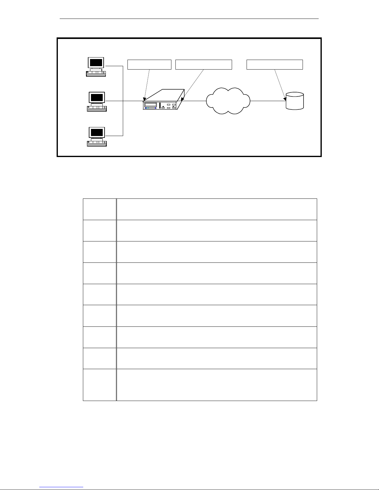
Figure 1.3 The Internet Connection over Frame Relay
An Example of the Setup Procedures via front panel
Step 1:
Step 3:
Step 4:
Under LAN Setup menu:
IP Address = 192.10.25.1
:
Under LAN Setup menu:
IP NetMask = 255.255.255.0
Under WAN Setup menu:
WAN Protocol = Frame Relay
Under FrRelay Setup menu:
Local Address = 192.72.240.252
Internet
Service
Step 6:
Step 7:
Step 8:
Step 9:
:
Under FrRelay Setup menu:
IP NetMask = 255.255.255.252
Under FrRelay Setup menu :
LMI type = ANSI T1.617
Under FrRelay Setup menu :
DLCI number = 150
Under Routing Table menu:
Default Gateway = 192.72.240.253
In an IP network, each host is configured with
its own IP Address and
a Gateway IP address = 192.10.25.1
1-5
Page 16
QUICK START
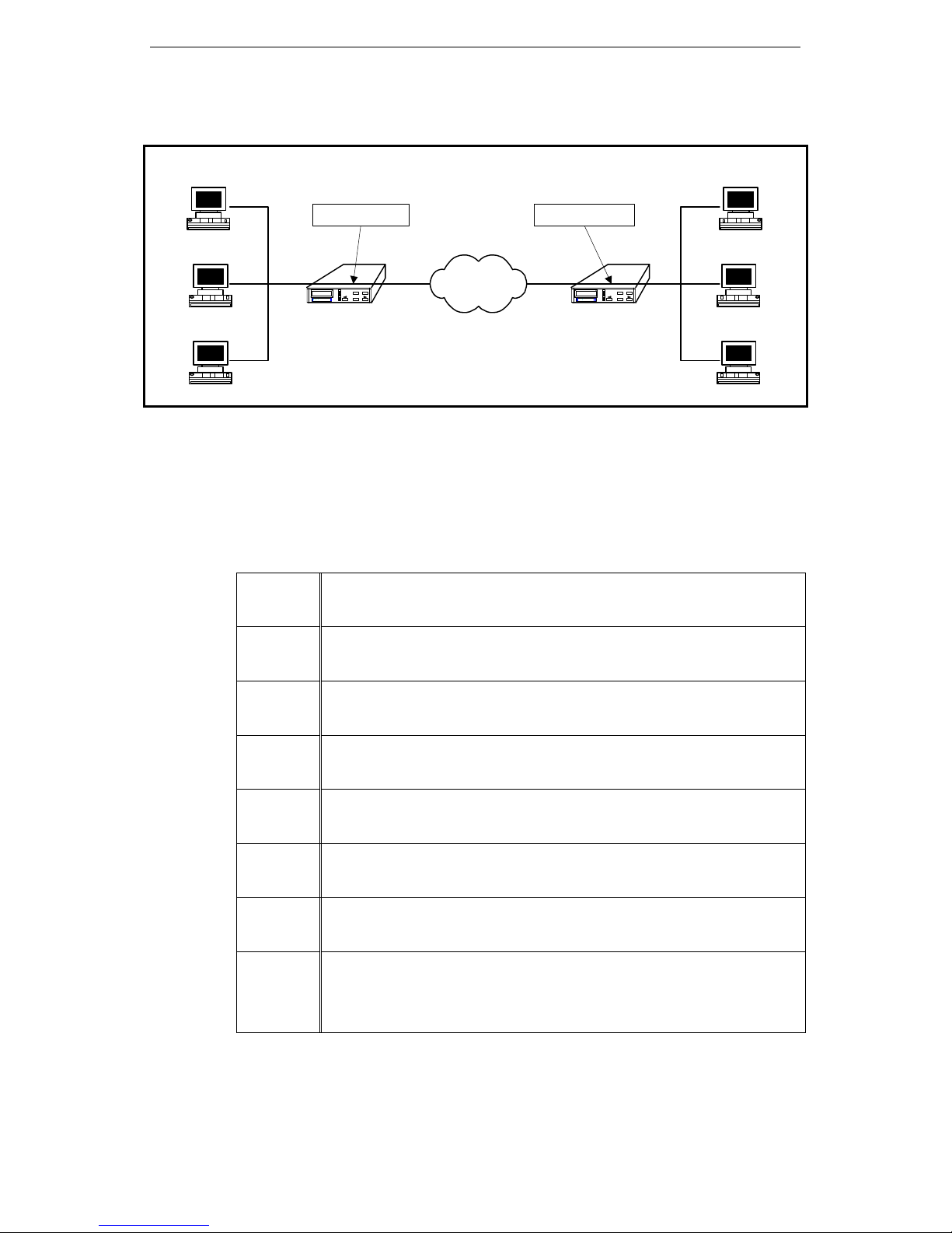
1.3 How to Operate and Setup Intranet Applications
Ethernet LAN
192.72.244.2192.72.244.1
Host
WAN
(Carrier)
Host
LAN
EXIT VO/DA
LANT
TAINET
LANR
RTS
CTS
WANpro 2000
TXD
RXD
ENTER
LINK
CSR
WANpro 2000
CST
WANpro 2000
#1
Host
Figure 1.4 The Intranet Connection over PPP
An Example of the Setup Procedures via front panel
1. WANpro 2000 #1 Setup
Step 1:
Under LAN Setup menu:
IP Address = 192.72.244.1
LAN
EXIT VO/DA
LANT
TAINET
LANR
RTS
CTS
WANpro 2000
TXD
RXD
ENTER
LINK
CSR
WANpro 2000
CST
WANpro 2000
#2
Ethernet LAN
Host
Host
Host
Step 2:
Step 3:
Step 4:
Step 5:
Step 6:
Step 7:
Step 8:
Under LAN Setup menu:
IP NetMask = 255.255.255.0
Under WAN Setup menu:
WAN Protocol = PPP
Under PPP Setup menu:
Local Address = 192.72.244.1
Under PPP Setup menu:
IP NetMask = 255.255.255.255
Under PPP Setup menu :
WAN Port Speed = Sync-External
Under Routing Table menu:
Default Gateway = 192.72.243.1
In an IP network, each host is configured with
its own IP Address and
a Gateway IP address = 192.72.244.1
1-6
Page 17

QUICK START
2. WANpro 2000 #2 Setup
End of the Chapter
Step 1:
Step 2:
Step 3:
Step 4:
Step 5:
Step 6:
Step 7:
Step 8:
Under LAN Setup menu:
IP Address = 192.72.243.1
Under LAN Setup menu:
IP NetMask = 255.255.255.0
Under WAN Setup menu:
WAN Protocol = PPP
Under PPP Setup menu:
Local Address = 192.72.243.1
Under PPP Setup menu:
IP NetMask = 255.255.255.255
Under PPP Setup menu :
WAN Port Speed = Sync-External
Under Routing Table menu:
Default Gateway = 192.72.244.1
In an IP network, each host is configured with
Its own IP Address and
a Gateway IP address = 192.72.243.1
1-7
Page 18

QUICK START
1-8
Page 19

INTRODUCTION
Overview
2.1 Tainet’s WANpro 2000
2.1.1 Features
2.1.2 Specifications
CHAPTER 2
INTRODUCTION
2.2 Applications
2-1
Page 20

INTRODUCTION
2.1 Tainet’s WANpro 2000
2.1.1 Features
l LCD display, provides instant information
l Front panel configuration, easy for use
l WAN port speed up to T1/E1
l Provides various DTE interface module
l Provides PPP & Frame Relay for high performance
Internet/Intranet access
l Supports RIP V1/V2, automatically create routing topology
l Embedded SNMP agent
l Provides NAT (Network Address Translation) function, offer
simply firewall and provide IP applications
l Provides DHCP(Dynamic Host Configuration Protocol) server for
automatically assigning IP addresses & other configuration
information to hosts on a TCP/IP network
l Provides "In band" (TELNET) and "Out band" (Console port)
Management
l Use flash memory, provides an easy way to upgrade
l ISDN interfaceà still not available
l Provides hardware interface 1 WAN and 1 LAN (10 BaseT)
2.1.2 Specifications
Power
l AC: 90~265V (47~60Hz)
l 5Watt
Dimensions
l Physical Dimensions: 180mm x 48mm x 262mm (W, H, D)
l Weight: 0.9kg
l Mounting: Desktop
Environment
l Operating Temperature: 0ºC to 50ºC
l Rel. Humidity: 5% ~ 95%, non-condensing
LAN Interface
l 10 Base-T auto detect
WAN Interface
l RS-232
Sync, Speed up to 128 Kbps
Aysnc, Speed up to 115200bps
l V.35 (Sync Speed up to 2Mbps)
l EIA-530 (Sync, Speed up to 2Mbps)
2-2
Page 21

INTRODUCTION
l X.21 (Sync, Speed up to 2Mbps)
Protocol
l PPP (RFC compliant)
l Frame Relay (RFC compliant)
l RIP V1, V2 (RFC compliant)
l IP (RFC compliant)
l ARP (RFC compliant)
l TELNET (RFC compliant)
l SNMP (RFC compliant)
l NAT
l DHCP
Management
l Control Port: RS-232 DCE (RJ-45 8pin phone jack)
l Async VT-100 or ANSI Emulation
l TELNET
l SNMP
LED Display
l LAN: LAN port enable/disable
l LANT: LAN port transmit
l LANR: LAN port receive
l RTS: WAN port DTE
l CTS: WAN port DCE
l TxD: WAN port transmission
l RxD: WAN port receive
l Link: PPP Link status
l CSR: Console port receive
l CST: Console port transmit
2-3
Page 22
INTRODUCTION
WANpro 2000
CST
WANpro 2000
CST
End of the Chapter
2.2 Applications
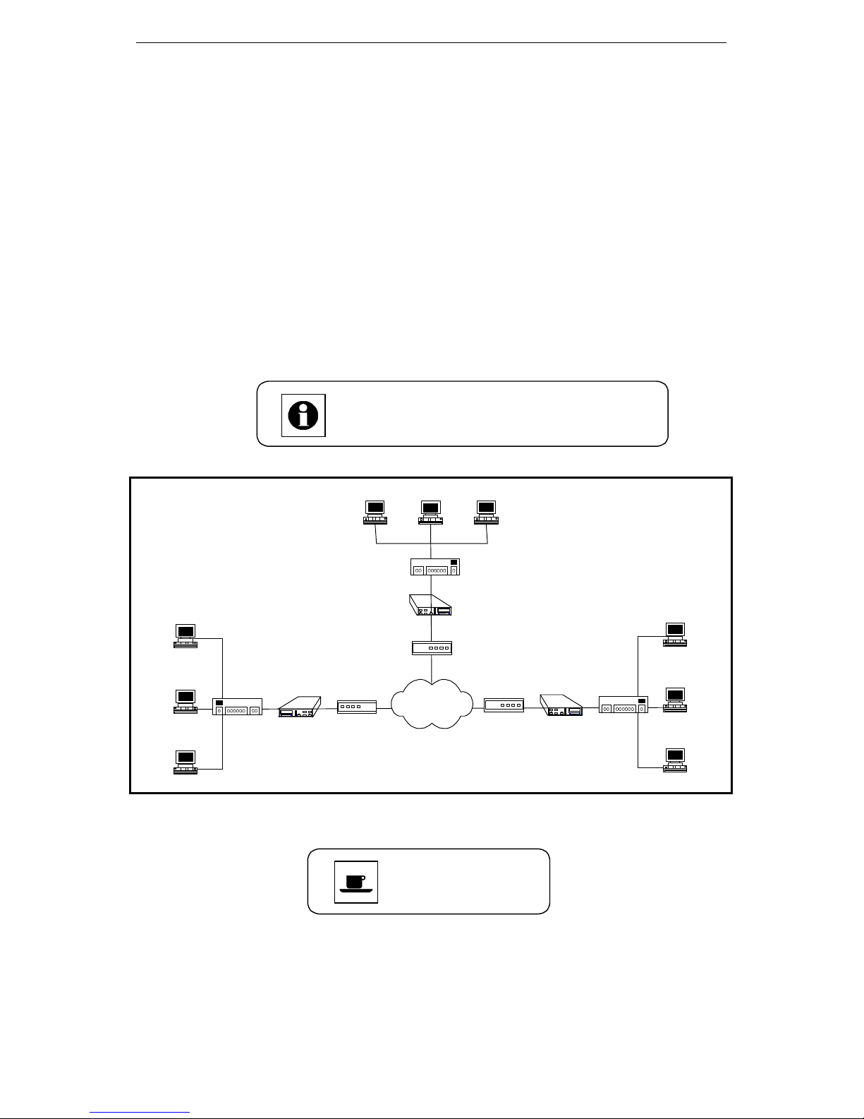
The application of the Tainet’s WANpro 2000 is broad. It is based on the
LAN and WAN network connectivity over a wide range of telephone line
distances and transmission line qualities. The Figure 2.1 has shown the
connection of the WANpro 2000 via the backbone of various DCE devices
to the Internet or Intranet Applications.
Nowadays, network access devices are not only required to provide reliable
service but they also strongly depend on well-developed network
management system. A solution of the embedded SNMP agent for Tainet’s
device is planned to manage more efficiently at the central office and
remote office.
The SNMP manager will be able to browse
and access the SNMP agent through Internet.
Ethernet LAN
Host
Host
Host
Host
Host
Host
Ethernet LAN
Hub
LAN
EXIT VO/DA
LANT
TAINET
LANR
RTS
CTS
WANpro 2000
TXD
RXD
ENTER
LINK
CSR
WANpro 2000
NTU
Hub
LAN
LANT
EXIT VO/DA
TAINET
LANR
RTS
WANpro 2000
CTS
TXD
RXD
ENTER
LINK
CSR
WANpro 2000
CST
WANpro 2000
xDSL
ISP
Telco
Voice band
Modem
LAN
EXIT VO/DA
LANT
LANR
RTS
CTS
TXD
ENTER
RXD
LINK
CSR
WANpro
2000
TAINET
WANpro 2000
Figure 2.1 Applications to xDSL Series Modem
Ethernet LAN
Hub
Host
Host
Host
2-4
Page 23

Configure and Monitor Via Front Panel
CHAPTER 3
Configure and Monitor Via Front Panel
Overview
3.1 Font Panel
3.2 Identify LEDs Light Status
3.3 Rear Panel
3.4 Front Panel
3-1
Page 24
Configure and Monitor Via Front Panel
3.1 Font Panel
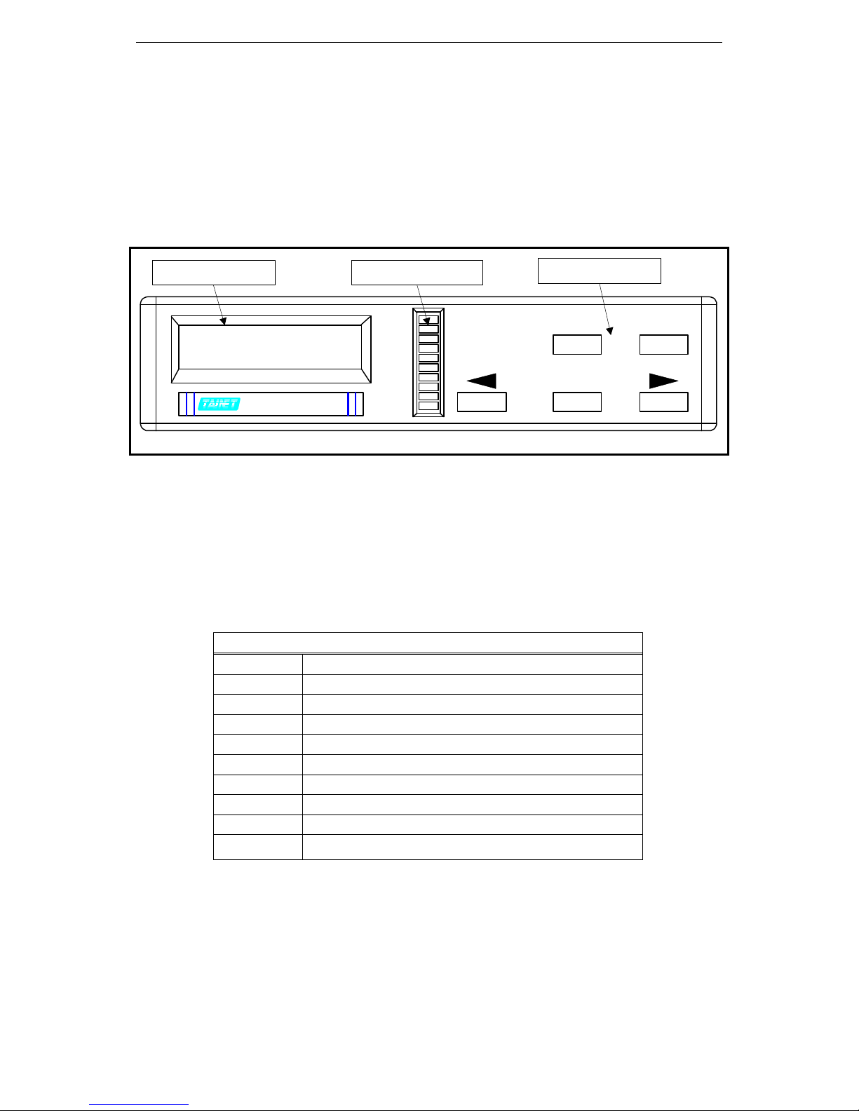
The front panel of the WANpro 2000 contains LCD Screen, LEDs Signal
Indicators and Keypad. The whole figure of the WANpro 2000 Front panel
could be found in the Figure 3.1A.
LCD Screen LEDs Indicators
LAN
TAINET
WANpro 2000
WANpro 2000
Figure 3.1A Front Panel of the Tainet’s WANpro 2000
LANT
LANR
RTS
CTS
TXD
RXD
LINK
CSR
CST
3.2 Identify LEDs Light Status
The LEDs light status explains in a comparison table below and some of the
useful information to tell user about the working status of the WANpro 2000
device. All of the details are shown in the table 3-1.
LED Display
LAN: LAN port enable/disable
LANT: LAN port transmit
LANR: LAN port receive
RTS: WAN port DTE
CTS: WAN port DCE
TxD: WAN port transmission
RxD: WAN port receive
Link: WAN Protocol layer link status
CSR: Console port receive
CST: Console port transmit
Keypad
EXIT VO/DA
ENTER
3-2
Table 3-1 LEDs definition
Page 25
Configure and Monitor Via Front Panel
3.3 Rear Panel
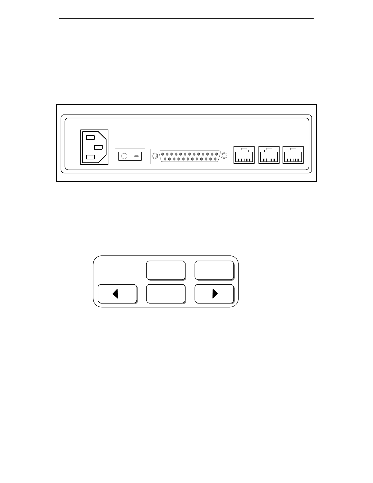
The Rear panel of the WANpro 2000 includes power, switch, and some
interface ports for the purposes of the network connection. The whole
figure of the WANpro 2000 Rear panel could be found in the Figure
3.1B.
AC INPUT
Figure 3.1B Rear Panel of the Tainet’s WANpro 2000
POWER
3.4 Front Panel Operation
1. Keypad and Cursor Control
- Keypad of the WANpro 2000 Device
- Cursor Control
EXIT HOME
ENTER
WAN
Console LAN ISDN
Where:
EXIT ; Press ‘EXIT’ keypad and move cursor up
ENTER ; Press ‘ENTER’ keypad and select the item
ç ; Press ‘Left’ keypad and move cursor left
è ; Press ‘Right’ keypad and move cursor right
HOME ; Press ‘Home’ keypad and exit cursor to main menu
3-3
Page 26
Configure and Monitor Via Front Panel
2. Startup Process
HOME
Power ON
Router
Initializing
After initialized Step
TAINET
WANpro 2000
After version menu, press
ENTER to Main Menu
Main Menu
LAN Setup
Go to
Sub-menu
Tree
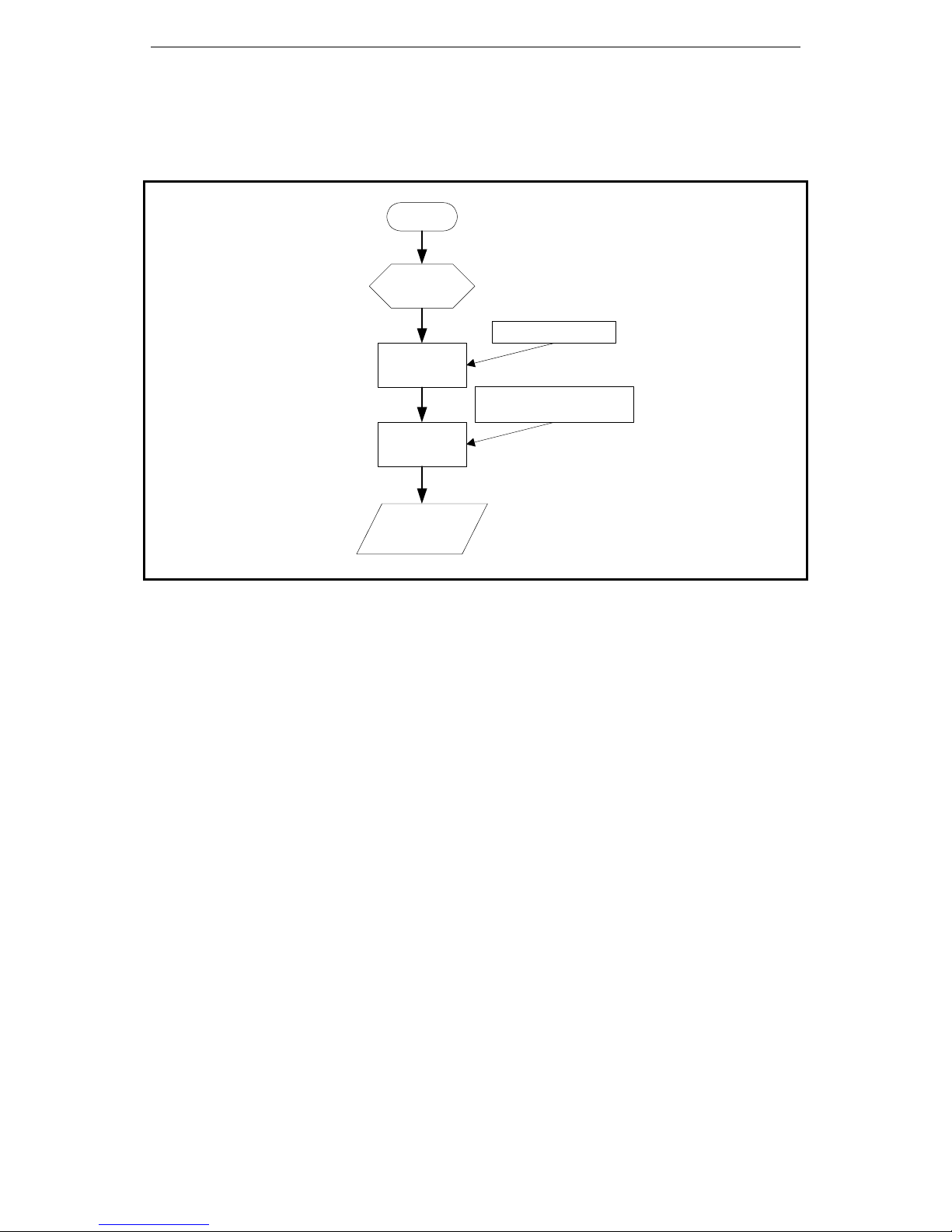
Figure 3.2 General Initialized Procedures of the WANpro 2000 Device
The main menu has been shown in conditions. It will constantly stop at the top
of the main menu while user might press ‘HOME’ keypad or not keying
anything for about 3 minutes. To go to the sub-menu, user should press ‘Enter’
to select and jump to the next layer of the menu tree.
3. LCD Display
The Tainet WANpro 2000 has the format of 2x16 characters and the LCD
display with automatic backlight control. Some of general questions that
you will encounter on the LCD display are show below.
3-4
Page 27

Configure and Monitor Via Front Panel
A. TOP Menu
Example:
TAINET
WANpro 2000
Description:
Ø You may use the “<”, “>” or “EXIT” keys to enter the
Version
Ø Menu. Press the “ENTER” key to get into the Main Menu.
B. Menu Select
Example 1: Example 2:
Main Menu
LAN Setup
Main Menu
Monitor
Description:
Ø You may use the “<” or “>” keys to browse the menu
selection:
LAN Setup à WAN Setup à Routing Table à
Device Control à Monitor.
Ø Press the ”ENTER” key to select the item.
Ø Press the “EXIT” key to quit the item.
C. Menu Screen
Example 1: Example 2:
LAN Setup
IP Address
LAN Rx Packets
Description:
Ø There are five menus:
LAN Setup à WAN Setup à Routing Table à
Device Control à Monitor.
Ø Use the “<” or “>” key to browse the sub-menu item.
Ø Press the “ENTER” key to select the item.
Ø Press the “EXIT” key to quit the item.
D. Editor Menu or Result Display
Example 1: Example 2:
IP Address
192.072.243.001
LAN Rx Packets
14705
Description:
Ø Use the “<” or “>” key to edit the IP address or IP Netmask
Ø Press the “ENTER” key to select the item.
Monitor
3-5
Page 28
Configure and Monitor Via Front Panel
4. LCD Menu Tree
WAN Router
MAIN MENU
Configuration using the LCD menu
IP Address
LAN Setup
LAN Setup
WAN Setup
WAN Setup
PPP Setup
PPP Setup
FrRelay Setup
FrRelay Setup
IP NetMask
WAN Protocol
Local IP
IP NetMask
Remote IP
WAN Port Speed
Local IP
IP NetMask
Remote IP
LMI Type
DLCI Number
PPP
Frame Relay
Sync - External
Async - 115200
Async - 57600
Async - 38400
Async - 19200
Async - 9600
Async - 4800
Async - 2400
Async - 1200
None LMI
ANSI T1.617
CCITT Q.933
LMI
Routing Table
Routing Table
Device Control
Device Control
Monitor
Monitor
Ddfault Gateway
Warm Start
Restore Default
LAN Rx Packets
LAN Tx Packets
LAN Rx Errors
WAN Rx Packets
WAN Tx Packets
WAN Rx Errors
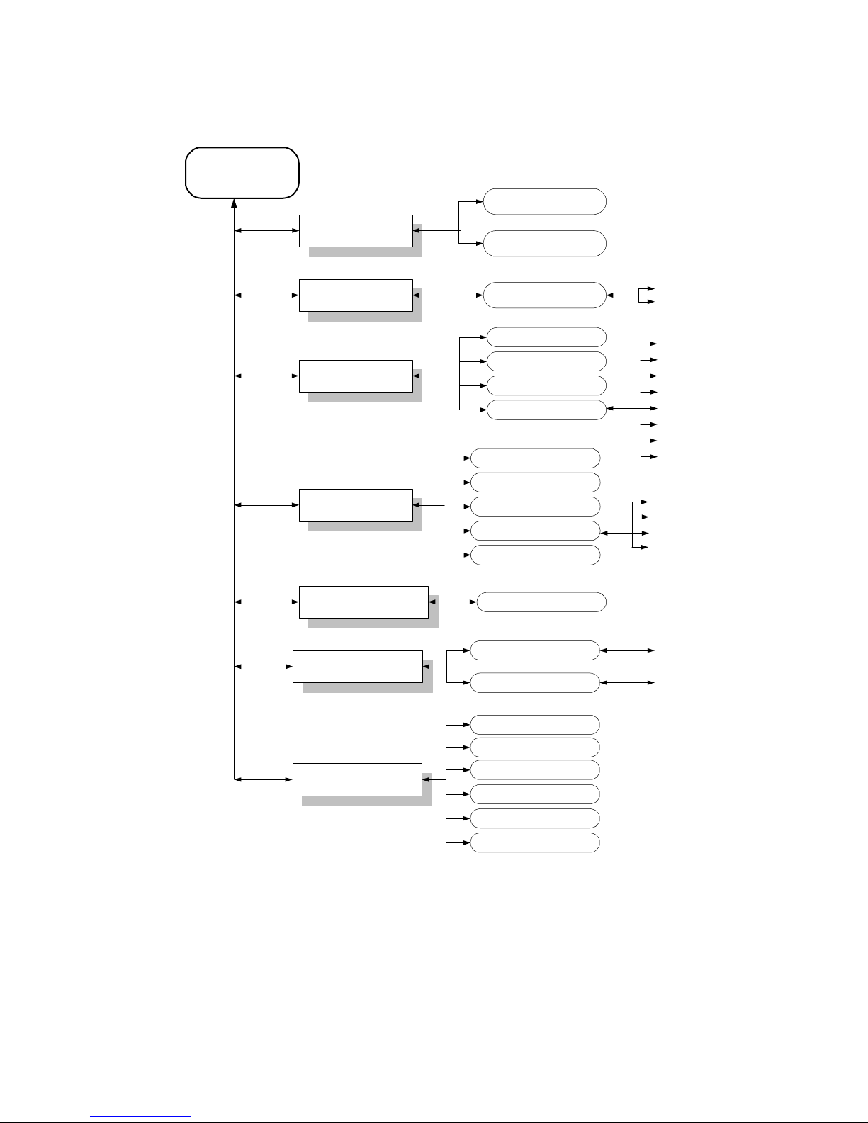
Figure 3.3 LCD Menu Tree
There are detail constructions of Menu tree in the next locus.
Enter to confirm
Enter to confirm
3-6
Page 29

Configure and Monitor Via Front Panel
The Description of the Configuration
A. LAN Setup
IP
Address
The IP address is a unique 4-byte (32-bit) numeric value
used to identify a network and a local host on that
network. Each IP address consists of four sets of decimal
numbers separated by the period (e.g. 192.72.243.1).
Each address is composed of two parts: a network part
and a host part. The network part identifies the unique
subnet that contains the host; the host part identifies the
actual host device.
IP
NetMask
B. WAN Setup
WAN
Protocol
C. PPP Setup
Local IP
IP
Netmask
Remote IP
WAN Port
Speed
The IP address netmask (also 32 bits, written in dotted
decimal notation) is used in conjunction with an IP
address to specify which bits of the address make up the
network part and which the host part. A one (1) in a
mask bit location means the corresponding bit in the IP
address is part of the network value; a zero (0) means
the corresponding bit is part of the host value.
The Tainet WANpro 2000 supports PPP and Frame
Relay. This parameter identifies what protocol WAN port
is used.
This parameter identifies the IP address for local WAN
port when the WAN protocol is selected PPP.
WAN port IP netmask when the WAN protocol is selected
PPP.
This parameter identifies the IP address for the WAN port
on a remote router when the WAN protocol is selected
PPP.
Select data speed & format when the WAN Protocol is
Selected PPP.
D. FrRelay Setup
Local IP
IP
Netmask
Remote IP
LMI type
DLCI
number
This parameter identifies the IP address for local WAN
port when the WAN protocol is selected Frame Relay.
WAN port IP netmask when the WAN protocol is selected
Frame Relay.
This parameter identifies the IP address for the WAN port
on a remote router when the WAN protocol is selected
Frame Relay.
Select Local Management Interface type to match the
public network, or the setting at the far-end in a private
network.
This Parameter identifier the Data Link Connection
Identifier address for the connection.
3-7
Page 30
Configure and Monitor Via Front Panel
End of the Chapter
E. Routing Table
Default
Gateway
F. Device Control
Warm
Start
If the WANpro 2000 receives a packet for an ”unknown”
destination (i.e. a packet with an IP address is not listed
in the routing table), it forwards that packet to the Default
Gateway if one has been defined.
Press the “ ENTER” key to restart the device.
Restore
Default
G. Monitor
LAN Rx
Packets
LAN Tx
Packets
LAN Rx
Errors
WAN Rx
Packets
WAN Tx
Packets
WAN Rx
Errors
Press the “ ENTER” key to reset the parameters to the
factory defaults.
The total number of input packets received from the LAN
interface.
The total number of packets sent to the LAN interface.
The total number of input packets received from the LAN
interface with specific errors (CRC error, frame error,
missed packet, unknown or unsupported protocol, etc).
The total number of input packets received from the WAN
interface.
The total number of packets sent to the WAN interface.
The total number of input packets received from the WAN
interface with specific errors (CRC error, frame error,
missed packet, unknown or unsupported protocol, etc).
Each sub-menu contains the individual selectable items. Some of
the sub-menu trees might be changed and come after later version.
User could download the updated software through Tainet’s
Internet Web site.
3-8
Only the registered user could have the right
to download the software.
Page 31

Configure and Monitor Via PCs or Terminals
CHAPTER 4
Configure and Monitor Via PCs or Terminals
Overview
4.1 Connect WANpro 2000 to PCs or Terminals
4.2 The ‘Configuration’
4.3 Main Menu:
4.4 Configuration Menu
4.4.1. System
4.4.2. PPP
4.4.3 FR
4.4.4. RIP_Setting
4.4.5. Routing_Table
4.4.6. Security
4.4.7 NAT
4.4.8 Filter
4.4.9 DHCP
4.5 Monitor Menu
4.5.1 Current_Configuration
4.5.2 Routing_Table
4.5.3 ARP_Table
4.5.4 Statistics
4.5.5 NAT_Buffer
4.5.6 DHCP
4.6 Device_Control
4.6.1 Warm_Start
4.6.2 Restore_Default
4.7 Diagnosis Menu
4.7.1 Ping
4-1
Page 32

Configure and Monitor Via PCs or Terminals
4.1 Connect WANpro 2000 to PCs or Terminals
The basic operation of the WANpro 2000 is similar to a normal PC. To view
the whole operation, user can feel comfortable of using a PC’s monitor instead
of the LCD panel.
The main function of the components could be described as,
1. Keyboard
The keyboard is used to select and manipulate the basic operation of
the WANpro 2000 including,
Ø Arrow Keys (Up, Down, Left, and Right)
Ø Number Keys (1 ~ 9) to select items
Ø Enter or Return Key (make the selection of each operation)
Ø Space Bar (Used to change a highlighted field and bring up next
choice)
Ø Special Function Keys
ESC (Quit and out of the operation)
2. Cursor
The cursor is used to indicate menu selections, option settings, and data
entry fields.
3. Pop-Up Boxes
Once an error or an information note was happened, a pop-up box will
appear over the current screen to assist operations.
The Console Port could assist the system maintenance for a Standalone
Termination Unit like Tainet’s WANpro 2000.
4-2
Page 33
Configure and Monitor Via PCs or Terminals
Procedures
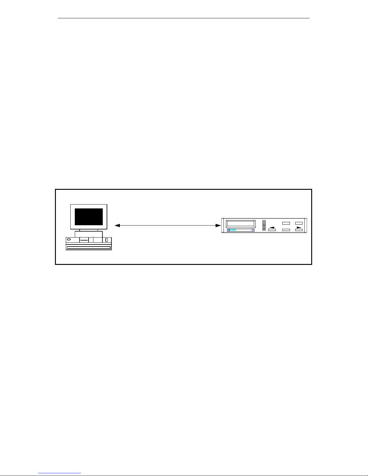
1. Make sure that PCs or Terminals of the COM port setting are set to
Ø At least 19200 baud rate
Ø 8-bit characters
Ø No parity
Ø 1 stop bit
Ø no flow control
2. Plug the RJ-45 with DB25 adapter to transfer RJ-45 into DB25
connector for attaching to the PCs or Terminal COM port. (WANpro
2000 Console Port with a DB25 adapter and PCs or Terminal COM
port – DB25 connector). (See Figure 4-1)
3. The Main Menu screen will display on the PC’s or Terminal’s Monitor
if the connection is successful. (See Figure 4-2)
PCs or Terminals
WANpro 2000
COM Port Console Port
V34 288 V42bis
L ANS CONNECT 9
WANpro 2000WANpro 2000
LAN
LANT
LANR
RTS
CTS
TXD
RXD
LINK
CSR
CST
EXIT VO/DA
ENTER
Figure 4.1 The Console Port Connection to PCs or Terminals
4-3
Page 34

Configure and Monitor Via PCs or Terminals
4.2 The ‘Configuration’
This section describes procedures for configuration and connection of the
Tainet WANpro 2000 to the Internet / Intranet.
1. Initial Setup
The WANpro 2000 features a setup program that can be initiated and
run from an ASCII Terminal or a PCs Terminal Emulator program.
The user needs to make sure that the Terminal Emulator is currently
connected to the RJ-45 Console port on the WANpro 2000 back panel.
2. Connecting to the Terminal
Ø The RJ-45 console port needs a DB25 adapter to be transferred
into the DB25 connector in order to make connection to the COM
port of the PCs or Terminals.
Ø Set COM port to work at a baud rate of 19.2 Kbps, N,8,1.
Ø Switch on the WANpro 2000 and you will see the following
screen.
3. Enter a Password
!!! Welcome to use TAINET WANpro 2000 !!!
Please Enter Password :
Ø The password could be up to eight digits in length. After key in
your password, the ‘Enter’ key is required.
Ø “root” with lower case is the default password for the
administration.
Ø The default password è “root”
4-4
Page 35
Configure and Monitor Via PCs or Terminals
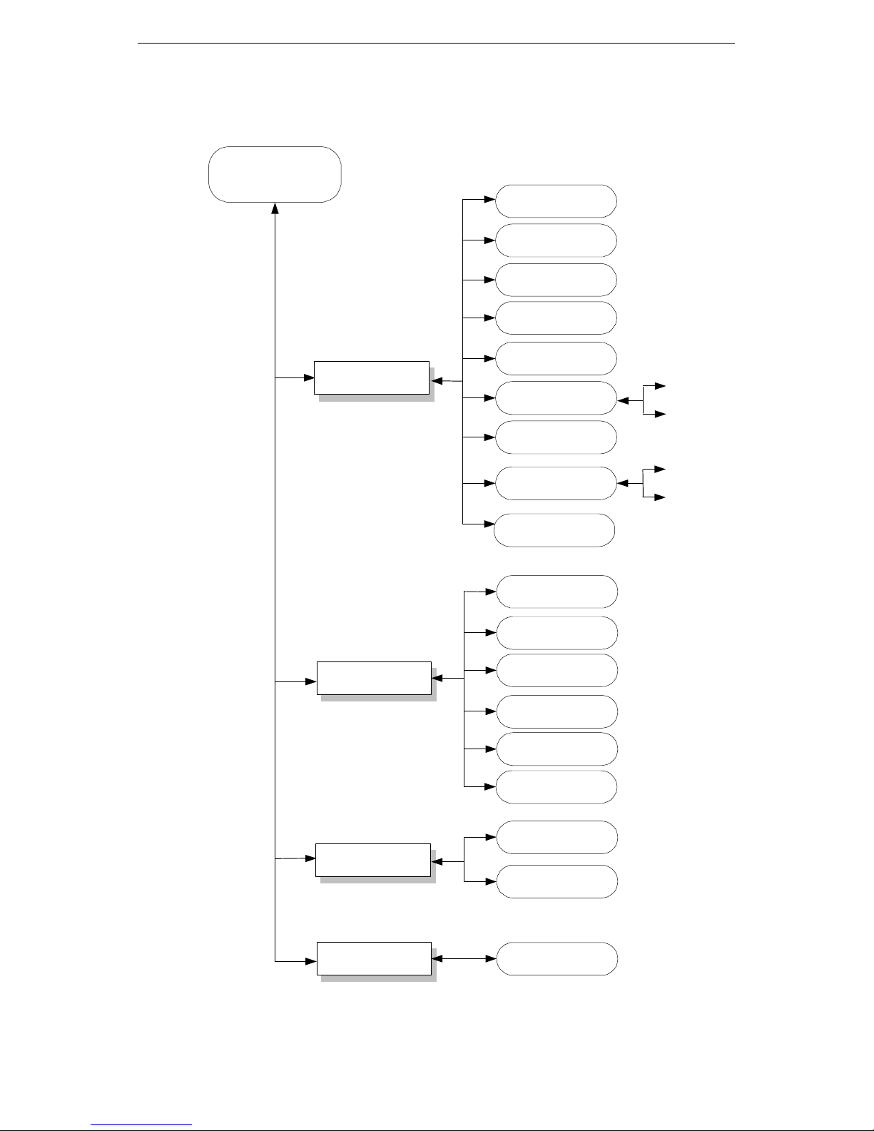
4. Main Menu Tree
MAIN MENU
Configuration
System
PPP
FR
RIP_Setting
Routing_Table
Static_Routing_Table
Security
Default_Gateway
NAT_Config
Monitoring
Device Control
Filter_Config
Incoming_Filter
Outgoing_Filter
DHCP
Current_Cinfiguration
Routing_Table
ARP_Table
Statistics
NAT_Buffer
DHCP
Warm_start
Restore_Default
Diagnosis
Figure 4.2 Main Menu Tree
Ping
4-5
Page 36
Configure and Monitor Via PCs or Terminals
4.3 Main Menu:
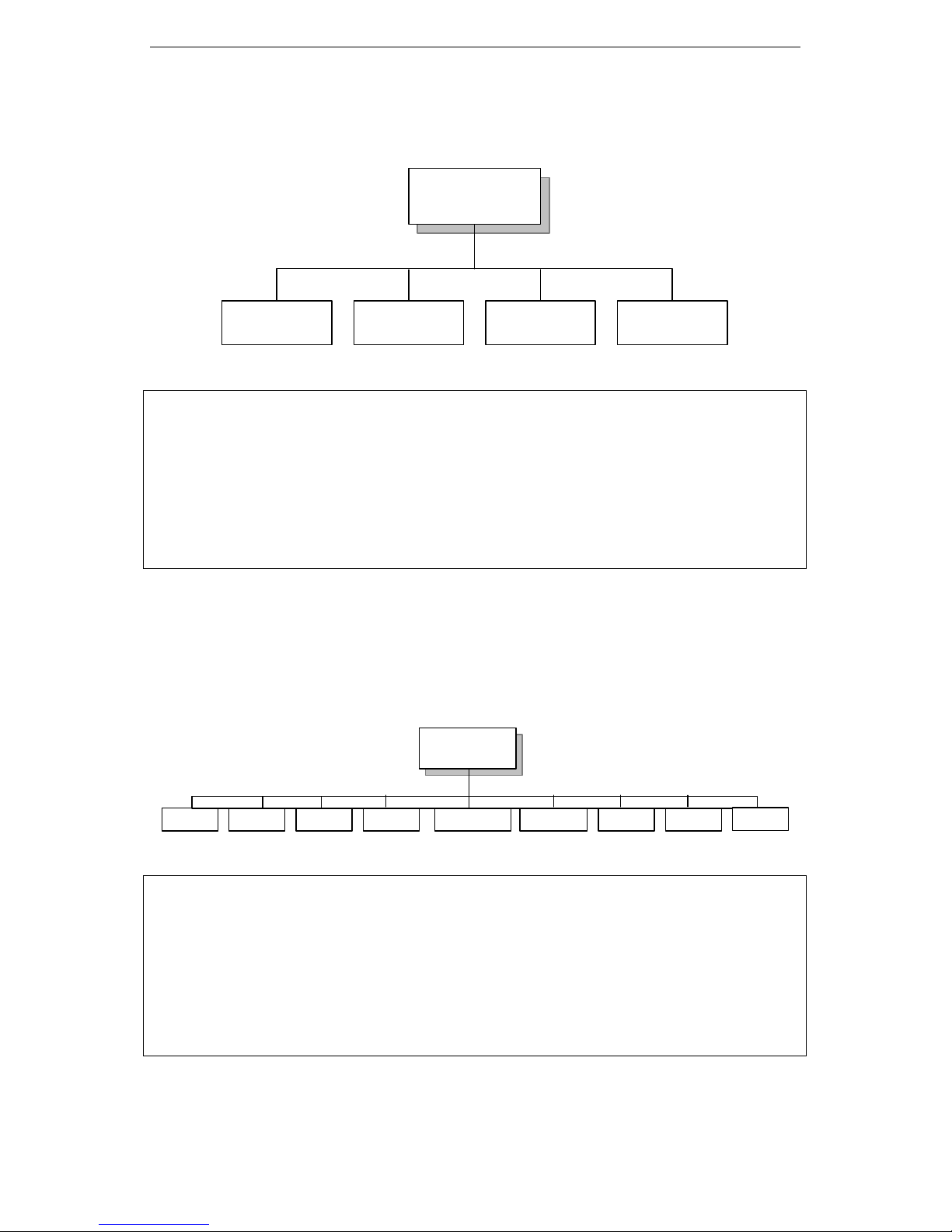
Main Menu
Configuration Monitoring Device_Control Diagnosis
Main MENU TAINET WANpro 2000
-------------------------------------------------------------------------------[Configuration] Monitoring Device_Control Diagnosis
System PPP FR RIP Routing_Table Security NAT Filter DHCP
Enter: select ESC: previous menu '<': left '>': right TAB: next item
The WANpro 2000 offers four major items of menu for user to configure and monitor
its own operation. All these four menu items are describing in following section.
4.4 Configuration Menu
CONFIGURATION
RIP Routing_Table SecurityFR FilterPPPSystem NAT
Configuration MENU TAINET WANpro 2000
-------------------------------------------------------------------------------[System] PPP FR RIP Routing_Table Security NAT Filter DHCP
Setup LAN IP, SubNetMask & WAN Protocol
DHCP
Enter: select ESC: previous menu '<': left '>': right TAB: next item
4-6
Page 37
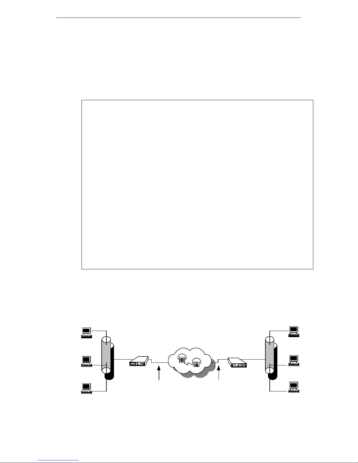
Configure and Monitor Via PCs or Terminals
4.4.1. System
This menu allows the administrator to configure the network parameters of
the WANpro 2000 for the LAN interface. These interface parameters should
be properly set before you make any network connections. The following
was shown after the user selects the sub-Menu of the ‘System’ menu.
Configuration MENU TAINET WANpro 2000
-----------------------------------------------------------------------------------------------[System] PPP FR RIP Routing_Table Security NAT Filter DHCP
Setup LAN IP, SubNetMask & WAN Protocol
Enter: select ESC: previous menu '<': left '>': right TAB: next item
LAN IP Address [10.0.0.254 ]
LAN IP NetMask [255.255.255.0 ]
WAN Protocol [PPP ]
SNMP [Enable ]
DHCP Daemon [Enable ]
Press [SPACE BAR] to Change Value
1. All IP address response is from WANpro 2000 IP address(Local IP).
2. There are the maximum of 300 IP to establish 1500 connection and 200
IP to establish 500 connection an 20 IP to process the maximum of 50
echo request operation at the same time.
Host
Host
Ethernet
EXITVOID
LANLANT
TAINET
LANR
WANpro 2000
RTSCTS
TXD
ENTER
RXDLINK
CSR
WANpro 2000
CST
WANpro 2000
LAN
EXIT VO/DA
LANT
LANR
RTSCTS
TXD
ENTER
RXDLINK
CSR
CST
WANpro 2000
TAINET
WANpro 2000
WANpro 2000
Ethernet
Host
Host
Host
Figure 4.3 Example of WANpro 2000 application
PPP over
RS-232(Sync/Async)or
V.35 or RS-530/X.21
PPP over
RS-232(Sync/Async)or
V.35 or RS-530/X.21
Host
4-7
Page 38

Configure and Monitor Via PCs or Terminals
The following describes the details of the setup items.
LAN
IP Address:
LAN
IP NetMask:
WAN
Protocol
SNMP
The IP address is a unique 4-byte (32-bit) numeric value
used to identify a network and a local host on that network.
Each IP address consists of four sets of decimal numbers
separated by periods (e.g. 192.72.243.1). Each address is
composed of two parts: a network part and a host part. The
network part identifies the unique subnet containing the
host; the host part identifies the actual host device.
An IP address netmask (also 32 bits, written in dotted
decimal notation) is used in conjunction with an IP address
to specify which bits of the address make up the network
part and which make up the host part. A one (1) in a mask
bit location means the corresponding bit in the IP address is
part of the network value; a zero (0) means the
corresponding bit is part of the host value.
The Tainet WANPro 2000 supports PPP and Frame Relay.
This parameter identifies what protocol WAN port is used.
Simple Network management protocol Enable or Disable.
SNMP V1 agent ,Support ISO standard MIB-II.
DHCP
Daemon
Dynamic Host Configuration Protocol Daemon Enable or
Disable.
4-8
Page 39

Configure and Monitor Via PCs or Terminals
SNMP Agent
The setup procedures for the “SNMP Agent” could be found as below.
a. Enter the main menu and select the “Configuration” item
Main MENU TAINET WANpro 2000
-------------------------------------------------------------------------------[Configuration] Monitoring Device_Control Diagnosis
System PPP FR RIP Routing_Table Security NAT Filter DHCP
Enter: select ESC: previous menu '<': left '>': right TAB: next item
b. After login to “Configuration” item and select “System”
Configuration MENU TAINET WANpro 2000
-------------------------------------------------------------------------------[System] PPP FR RIP Routing_Table Security NAT Filter DHCP
Setup LAN IP, SubNetMask & WAN Protocol
Enter: select ESC: previous menu '<': left '>': right TAB: next item
LAN IP Address [10.0.0.254 ]
LAN IP NetMask [255.255.255.0 ]
WAN Protocol [PPP ]
SNMP [Enable ]
DHCP Daemon [Enable ]
The following describes the details of the setup items.
SNMP: Disable/Enable SNMP agent.
Now the SNMP agent only provides “SET” and “GET”, and set the
Default Value as:
“Get Community: [Public]”, “Set Community: [Telnet Password]”
for SNMP Manager used.
4-9
Page 40

Configure and Monitor Via PCs or Terminals
4.4.2. PPP
This menu allows the administrator to configure the network parameters of
the WANpro 2000 for the WAN interface about PPP protocol. These
interface parameters should be properly set before you make any network
connections. The following was shown after the user selects the sub-menu
of the “PPP” Menu.
Configuration MENU TAINET WANpro 2000
-------------------------------------------------------------------------------System [PPP] FR RIP Routing_Table Security NAT Filter DHCP
Setup PPP
Enter: select ESC: previous menu '<': left '>': right TAB: next item
PPP Local IP Address [192.72.200.100 ]
PPP IP NetMask [255.255.255.255 ]
PPP Remote IP Address [192.72.200.200 ]
PPP Port Speed [Sync-External ]
NAT [Disable ]
Filter [Disable ]
PPP
Local
IP Address:
PPP
IP NetMask:
PPP
Remote
IP Address:
PPP
Port Speed
This parameter identifies the IP address for local WAN port
when the WAN protocol is selected PPP.
WAN port IP netmask when the WAN protocol is selected
PPP.
This parameter identifies the IP address for the WAN port on
a remote router when the WAN protocol is selected PPP.
Select data speed & format when the WAN Protocol is
Selected PPP.
NAT
Filter
4-10
Network Address translation Enable or Disable when the
WAN protocol is selected PPP.
IP Filter Enable or Disable when the WAN protocol is
selected PPP.
Page 41

Configure and Monitor Via PCs or Terminals
4.4.3 FR
This menu allows the administrator to configure the network parameters of
the WANpro 2000 of the WAN interface about Frame Relay protocol.
Configuration MENU TAINET WANpro 2000
-------------------------------------------------------------------------------System PPP [FR] RIP Routing_Table Security NAT Filter DHCP
Setup Frame Relay
Enter: select ESC: previous menu '<': left '>': right TAB: next item
LMI Type [ANSI]
DLCI No. IP Address IP NetMask Remote IP
NAT Filter
1. [100] [192.72.254.200] [255.255.255.255] [192.72.254.100]
[Disable] [Disable]
LMI Type:
DLCI NO.
IP Address
IP NetMask
Remote IP
NAT
Filter
Select Local Management Interface type to match the public
network, or the setting at the far-end in a private network.
This parameter identifiers the Data Link Connection
Identifier address for the connection.
This parameter identifies the IP address for local WAN port
when the WAN protocol is selected Frame Relay.
WAN port IP netmask when the WAN protocol is selected
Frame Relay.
This parameter identifies the IP address for the WAN port on
a remote router when the WAN protocol is selected Frame
Relay.
Network Address Translation Enable or Disable when the
WAN protocol is selected Frame Relay.
IP Filter Enable or Disable when the WAN protocol is
selected Frame Relay.
4-11
Page 42

Configure and Monitor Via PCs or Terminals
4.4.4. RIP_Setting
Routers do not need information on the complete path to a remote site –
they only need information on how to get to the next hop (router). Routers
often use dynamic routing to gain information on the location of the next
hop for a connection. The Tainet WANpro 2000 supports two standard
routing information protocols, RIP I and RIP II. The RIP I and RIP II
routing protocols automatically exchange the routing information and they
are used extensively throughout private IP networks and the Internet. The
following was shown after the user selects the sub-Menu of the ‘System’
menu.
Configuration MENU TAINET WANpro 2000
------------------------------------------------------------------------------- System PPP FR [RIP] Routing_Table Security NAT Filter DHCP
Setup RIP Option
Enter: select ESC: previous menu '<': left '>': right TAB: next item
Routed [Disable]
Mode [Passive]
LAN WAN-1
Send_Ver [RIP-1] [RIP-1]
Recv_Ver [RIP-1&2] [RIP-1&2]
Default Route [0 ] [0 ]
Horizon [SPLIT ] [SPLIT ]
Next Hop advertise [No ] [No ]
Sub Accept [Yes] [Yes]
Sub Advertise [Yes] [Yes]
Press [SPACE BAR] to Change Value
4-12
Page 43

Configure and Monitor Via PCs or Terminals
The following describes the details of the setup items.
LAN:
WAN:
Routed:
Mode:
Send_Ver:
Recv_Ver:
Refers to the LAN interface.
Refers to the WAN interface.
[Enable] enables RIP.
[Disable] disables RIP.
The Tainet WANpro 2000 can execute passive or active RIP.
When executing passive RIP, the Tainet WANpro 2000
revises its routing table based on the routing update
information it receives, but does not advertise self-routing
information to other routers. When configured for active RIP,
the WANpro 2000 acts as a full router; it not only listens for
updates but also advertises it routing table information
every 30 seconds.
[Passive] enables passive RIP.
[Active] enables active RIP.
Controls the version(s) of RIP advertisements. Available
with active RIP only.
[OFF] Disables the version(s) of RIP advertisement.
[RIP-1] Enables the version of RIP-1 advertisement.
[RIP-2] Enables the version of RIP-2 advertisement.
Controls the version(s) of RIP updates that are accepted.
[OFF] Disables the version(s) of RIP upgrades that
are accepted.
[RIP-1] Enables the version of RIP-1 upgrades that
are accepted.
[RIP-2] Enables the version of RIP-2 upgrades that
are accepted
[RIP-1&2] Enables the versions of RIP-1 and RIP-2
upgrades that are accepted.
Default
Route:
Horizon:
Controls and sets the Tainet WANpro 2000 to advertise itself
as the default router.
[0]: Disabled
[1~15]: Enables and specifies the number of hops to
a destination.
Controls the spilt horizon and poison reverse mechanisms.
Available with active RIP only.
[SPLIT] Split horizon
[POISON] Poison reverse
4-13
Page 44
Configure and Monitor Via PCs or Terminals
Next Hop
advertise:
Sub Accept:
Sub
Advertise:
Specifies whether or not the next hop value is included in
the RIP version 2 advertisements. Available with active RIP
only.
[YES] Next hop value will be included in the RIP
version 2 advertisements.
[NO] Next hop value will not be included in the RIP
version 2 advertisements.
Controls whether or not subnet routes are accepted in
updates.
[YES] Subnet routes will be accepted in updates.
[NO] Subnet routes will not be accepted in
updates.
Controls whether or not the RIP advertises subnets.
Available with active RIP only.
[YES] RIP advertises subnets
[NO] RIP does not advertise subnets
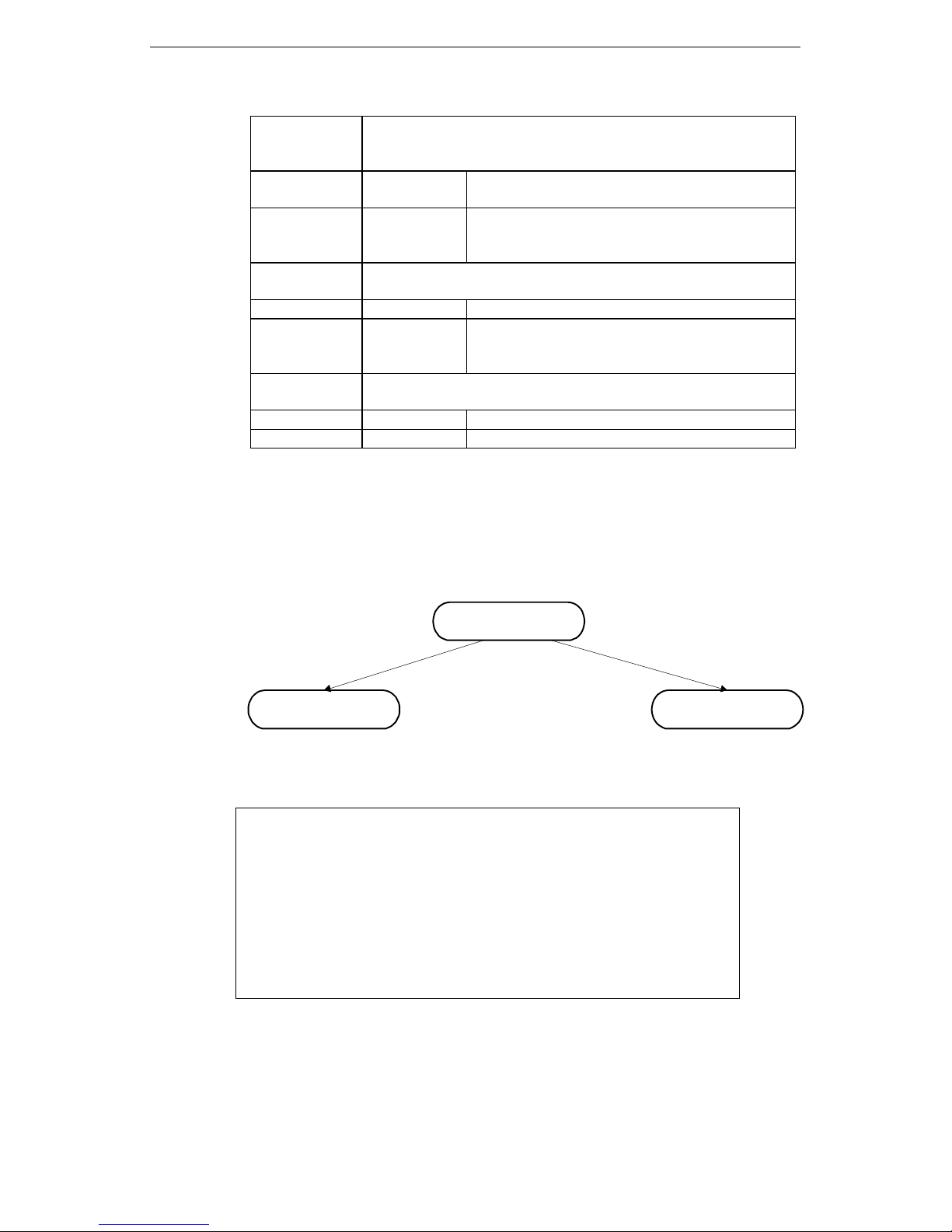
4.4.5. Routing_Table
To select the “Routing_Table” sub-menu under the “System” menu, the
topics will include,
Routing Table
Static Routing
Table
Default getwary
The pop-up screen of the Routing_Table menu will be found as,
Routing_Table MENU TAINET WANpro 2000
-------------------------------------------------------------------------------[Static_Routing_Table] Default_Gateway
Edit Static Routing Table
Enter: select ESC: previous menu '<': left '>': right TAB:
next item
4-14
Page 45

Configure and Monitor Via PCs or Terminals
a. Static_Routing _Table
Static routes are those routes that you define in the Tainet WANpro
2000 manually. Static routes exist permanently unless you change
them. You may use static routes to establish fixed connections and to
augment the RIP routing table. The details of the Configuration for
‘Static_Routing_Table’ could be found as follows.
Routing_Table MENU TAINET WANpro 2000
-------------------------------------------------------------------------------[Static_Routing_Table] Default_Gateway
Edit Static Routing Table
Enter: select ESC: previous menu '<': left '>': right TAB: next item
Destination Address Net Mask Next Hop Metric
[203.72.2.1 ] [ ] [ ] [ ]
[ ] [ ] [ ] [ ]
[ ] [ ] [ ] [ ]
[ ] [ ] [ ] [ ]
[ ] [ ] [ ] [ ]
[ ] [ ] [ ] [ ]
[ ] [ ] [ ] [ ]
[ ] [ ] [ ] [ ]
The following describes the details of the setup items.
Destination
Address:
Net Mask:
Next Hop:
Metric:
Enter the destination IP address in this column.
Enter the IP netmask in this column.
Enter the IP address of the next hop (router). The next
hop must be one of the following: a valid IP address on a
remote LAN or the IP address at the remote end of a PPP
link.
Enter a value of 1 through 15 to denote the number of
hops (the metric) to the endpoint destination. If the routing
tables show more than one route to a destination, the
Tainet WANpro 2000 will select the route with the smallest
metric.
4-15
Page 46

Configure and Monitor Via PCs or Terminals
b. Default_Gateway:
If the Tainet WANpro 2000 receives a packet for an unknown
destination, it forwards that packet to the default gateway as long as
one has been defined. The details of the configuration for
‘Default_Gateway’ could be found as follows.
Routing_Table MENU TAINET WANpro 2000
-------------------------------------------------------------------------------Static_Routing_Table [Default_Gateway]
Edit Default Gateway Table
Enter: select ESC: previous menu '<': left '>': right TAB: next
item
*Primary Default Gateway [192.72.244.2 ]
The following describes the details of the setup items.
Primary Default Gateway: Enter the default gateway IP address in this column.
4-16
Page 47

Configure and Monitor Via PCs or Terminals
4.4.6. Security
Configuration MENU TAINET WANpro 2000
------------------------------------------------------------------------------- System PPP FR RIP Routing_Table [Security] NAT Filter DHCP
Edit Console & Telnet Password
Enter: select ESC: previous menu '<': left '>': right TAB: next item
Please Enter Console Password :
[Note]: The default console password à ”root’’.
Configuration MENU TAINET WANpro 2000
------------------------------------------------------------------------------- System PPP FR RIP Routing_Table [Security] NAT Filter DHCP
Edit Console & Telnet Password
Note:
Enter: select ESC: previous menu '<': left '>': right TAB: next item
Console Port Password [root ]
Telnet [Enable ]
Telnet Username [root ]
Telnet Password [root ]
Front Panel [*Enable ]
Enable:
Ø Enable :using Front Panel
Ø Disable :Front Panel Lock
4-17
Page 48

Configure and Monitor Via PCs or Terminals
The following describes the details of the setup items.
Console Port
Password:
Telnet:
Telnet Username:
Telnet Password:
[Note]: The default Telnet User name à ”root’’.
Type your password. The password can be up to eight
characters in length.
Enable or Disable the TELNET management of the Tainet
WANpro 2000.
Type your TELNET username. The username can be up to
eight characters in length.
Type your TELNET password. The password can be up to
eight characters in length. Press the ENTER key. The
password allows you to enter the configuration module.
The default Telnet Password à ”root’’.
4-18
Page 49
Configure and Monitor Via PCs or Terminals
Front Panel Lock
The setup procedures for the “Front Panel Lock” could be found as below.
a. Enter the main menu and select the configuration item
Main MENU TAINET WANpro 2000
-------------------------------------------------------------------------------[Configuration] Monitoring Device_Control
System PPP FR RIP Routing_Table Security NAT Filter DHCP
Enter: select ESC: previous menu '<': left '>': right TAB: next item
b. After login to “Configuration” item, select “Security”
(Default is setup to “root”)
Configuration MENU TAINET WANpro 2000
------------------------------------------------------------------------------- System PPP FR RIP Routing_Table [Security] NAT Filter DHCP
Edit Console & Telnet Password
Enter: select ESC: previous menu '<': left '>': right TAB: next item
Please Enter Console Password :
c. After login to “Security, select “Front Panel Lock” to enable/disable
Configuration MENU TAINET WANpro 2000
------------------------------------------------------------------------------- System PPP FR RIP Routing_Table [Security] NAT Filter DHCP
Edit Console & Telnet Password
Enter: select ESC: previous menu '<': left '>': right TAB: next item
Console Port Password [root ]
Telnet [Enable ]
Telnet Username [root ]
Telnet Password [root ]
Front Panel [Disable ]
The default value is “Enable”. When enable this function.
Tainet2000 allows user get information from LCD display, but can
not change the setting.
4-19
Page 50

Configure and Monitor Via PCs or Terminals
4.4.7 NAT
NAT is a method by which many network IP Address and their TCP/UDP
ports are translated into a single network address and its TCP/UDP ports,
transparent to end-users. This NAT facility provides a mechanism to
connect a routing realm with private addresses to the external routing
network with globally unique registered addresses.
NAT (Network Address Translation)
The setup procedures for the NAT configuration could be found as below.
a. Enter the main menu and select the configuration item
Main MENU TAINET WANpro 2000
-------------------------------------------------------------------------------[Configuration] Monitoring Device_Control
System PPP FR RIP Routing_Table Security NAT Filter DHCP
Enter: select ESC: previous menu '<': left '>': right TAB: next item
b. After login to “Configuration” item, select “NAT_Config”
Configuration MENU TAINET WANpro 2000
-------------------------------------------------------------------------------System PPP FR RIP Routing_Table Security [NAT] Filter DHCP
Setup NAT Configuration
Enter: select ESC: previous menu '<': left '>': right TAB: next item
Proxy Port List
Protocol PORT IP
[TCP] [0 ] [0.0.0.0 ]
[TCP] [0 ] [0.0.0.0 ]
[TCP] [0 ] [0.0.0.0 ]
[TCP] [0 ] [0.0.0.0 ]
[TCP] [0 ] [0.0.0.0 ]
ICMP [0.0.0.0 ]
IP Pass-Through List
[0.0.0.0 ] [0.0.0.0 ]
[0.0.0.0 ] [0.0.0.0 ]
[0.0.0.0 ] [0.0.0.0 ]
4-20
Press [SPACE BAR] to Change Value
Page 51
Configure and Monitor Via PCs or Terminals
The following describes the details of the setup items.
NAT: Disable or Enable NAT function (default: Enable)
Proxy port list: Used to create incoming entry between internal and
external network, which is separated by NAT function.
Proxy port list/Protocol: Select which protocol should be used for current entry.
TCP and UDP can be chosen.
Proxy port list/ Port: Identify port number for the services, which will be
allowed to access by the user from external network.
Proxy port list/ IP: Identify the IP address of the HOST who provides the
services to other users in external network.
Proxy port list/ ICMP: Identify the IP address of the HOST who should reply the
“ICMP request” packet from external network.
(Default: 0.0.0.0)
If no IP address assigned in this field (default), any
HOST won’t reply the “ICMP request” packet.
IP pass-through list: IP pass-through function. Create the entry for incoming
and outgoing traffic. The traffic for the HOST who on this
list will not be processed by NAT algorithm.
4-21
Page 52

Configure and Monitor Via PCs or Terminals
Example:
Configuration MENU TAINET WANpro 2000
------------------------------------------------------------------------------------------------------ System PPP FR RIP Routing_Table Security [NAT] Filter DHCP
Setup NAT Configuration
Enter: select ESC: previous menu '<': left '>': right TAB: next item
Proxy Port List
Protocol PORT IP
[TCP] [23 ] [10.0.0.254 ]
[UDP] [53 ] [10.0.0.1 ]
[TCP] [0 ] [0.0.0.0 ]
[TCP] [0 ] [0.0.0.0 ]
[TCP] [0 ] [0.0.0.0 ]
ICMP [10.0.0.254 ]
IP Pass-Through List
[10.0.0.98 ] [0.0.0.0 ]
[0.0.0.0 ] [0.0.0.0 ]
[0.0.0.0 ] [0.0.0.0 ]
Explain:
1. Only signal IP 10.0.1.5 for communication, expect 10.0.0.98 other IP address
will change to 10.0.1.5.
2. TCP/23 è Telnet server, all from external network’s telnet service request of
10.0.1.5 will transmit to 10.0.0.254.
3. UDP/53 è DNS, all from external network’s DNS question of 10.0.1.5 will
transmit to 10.0.0.1
4-22
Page 53
Configure and Monitor Via PCs or Terminals
4.4.8 Filter
IP filters are a security feature that allow you to:
• Keep unauthorized people from accessing your LAN resources.
• Restrict traffic on the WAN link.
You can use IP filter to restrict the types of Internet traffic that are permitted
to access your LAN, and you can restrict your LAN workstation users to only
a specific application on the internet.
Filter
Incoming_Filter Outgoing_Filter
The setup procedures for the “Filter Configuration” could be found as
below.
a. Enter the main menu and select the configuration item
Main MENU TAINET WANpro 2000
-------------------------------------------------------------------------------[Configuration] Monitoring Device_Control
System PPP FR RIP Routing_Table Security NAT Filter DHCP
Enter: select ESC: previous menu '<': left '>': right TAB: next item
Login to “Configuration” item.
b. After login to “Configuration” item, select “Filter_Config”
Configuration MENU TAINET WANpro 2000
------------------------------------------------------------------------------- System PPP FR RIP Routing_Table Security NAT [Filter] DHCP
Incoming_Filter Outgoing_Filter
Enter: select ESC: previous menu '<': left '>': right TAB: next item
Choose “Filter”.
4-23
Page 54

Configure and Monitor Via PCs or Terminals
c. After login to “Filter” item, select “Incoming filter”
Filter_Config MENU TAINET WANpro 2000
-------------------------------------------------------------------------------[Incoming_Filter] Outgoing_Filter
Incoming Filter Config
Enter: select ESC: previous menu '<': left '>': right TAB: next item
Incoming filter: For incoming filter config.
Outgoing filter: For outgoing filter config.
d. The “Incoming Filter” and “Outgoing Filter” includes:
Filter_Config MENU TAINET WANpro 2000
-------------------------------------------------------------------------------[Incoming_Filter] Outgoing_Filter
Incoming Filter Config
Enter: select ESC: previous menu '<': left '>': right TAB: next item
Type Source IP MASK-Bit Destination IP MASK-Bit Protocol Port
[No ] [0.0.0.0 ] [0 ] [0.0.0.0 ] [0 ] [ALL ] [0 ]
[No ] [0.0.0.0 ] [0 ] [0.0.0.0 ] [0 ] [ALL ] [0 ]
[No ] [0.0.0.0 ] [0 ] [0.0.0.0 ] [0 ] [ALL ] [0 ]
[No ] [0.0.0.0 ] [0 ] [0.0.0.0 ] [0 ] [ALL ] [0 ]
[No ] [0.0.0.0 ] [0 ] [0.0.0.0 ] [0 ] [ALL ] [0 ]
[No ] [0.0.0.0 ] [0 ] [0.0.0.0 ] [0 ] [ALL ] [0 ]
[No ] [0.0.0.0 ] [0 ] [0.0.0.0 ] [0 ] [ALL ] [0 ]
[No ] [0.0.0.0 ] [0 ] [0.0.0.0 ] [0 ] [ALL ] [0 ]
[No ] [0.0.0.0 ] [0 ] [0.0.0.0 ] [0 ] [ALL ] [0 ]
[No ] [0.0.0.0 ] [0 ] [0.0.0.0 ] [0 ] [ALL ] [0 ]
[Permit] Any.
Press [SPACE BAR] to Change Value
4-24
Page 55
Configure and Monitor Via PCs or Terminals
The following describes the details of the setup items.
Type: Identify the process model of current entry.
No: No process will be done (default)
Permit: The packet that meets the requirement in this entry will be
send/received by Wan Pro.
Deny: The packet which meet the requirement in this entry will not be
sent/received by Wan Pro.
Source IP: Identify the source IP address for current entry. It can be a
HOST or Network.
MASK-bit: Identify the Subnet mask of the source IP. Presented by the
number of the mask bit.
Destination IP: Identify the destination IP address of current entry. It can be a
HOST or Network.
MASK-bit: Identify the Subnet mask of the source IP. Presented by the
number of the mask bit.
Protocol: Identify the protocol type of current entry.
ALL: Include TCP/UDP/ICMP
TCP: Current entry only effected TCP protocol.
UDP: Current entry only effected UDP protocol.
ICMP: Current entry only effected ICMP protocol.
Port: Identify the port number of the services.
In the bottom of this manual, Tainet2000 allows
user to “Permit” or “Deny” any kind of packet.
4-25
Page 56

Configure and Monitor Via PCs or Terminals
Main MENU TAINET WANpro 2000 Version 2.28t
Configuration MENU TAINET WANpro 2000 Version 2.28t
4.4.9 DHCP
Dynamic Host Configuration Protocol (DHCP) provides a method for
passing configuration to hosts on a TCP/IP network. DHCP is based on the
Bootstrap Protocol (BOOTP), adding the capability of automatic allocation
of reusable IP addresses and additional configuration options.
The setup procedures for DHCP could be found as below:
a. Enter the main menu and select the configuration item
-------------------------------------------------------------------------------------------------------
[Configuration] Monitoring Device_Control Diagnosis
System PPP FR RIP Routing_Table Security NAT Filter DHCP
Enter: select ESC: previous menu '<': left '>': right TAB: next item
'
b. After login to “Configuration” item, select “DHCP”
-------------------------------------------------------------------------------------------------------
System PPP FR RIP Routing_Table Security NAT Filter [DHCP]
DHCP Daemon Configuration
Enter: select ESC: previous menu '<': left '>': right TAB: next item
Default Lease Time(in secs) [86400 ]
Gateway [172.16.0.254 ]
DNS Server [172.16.0.1 ]
WINS Server [172.16.0.1 ]
IP Address Pool for Dynamic Leases
Range from [172.16.5.101 ]
to [172.16.5.105 ]
IP-Ethernet Address Mapping for Fixed Leases
IP Address Ethernet Address IP Address Ethernet Address
[0.0.0.0 ] [000000000000] [0.0.0.0 ] [000000000000]
[0.0.0.0 ] [000000000000] [0.0.0.0 ] [000000000000]
[0.0.0.0 ] [000000000000] [0.0.0.0 ] [000000000000]
[0.0.0.0 ] [000000000000] [0.0.0.0 ] [000000000000]
4-26
Page 57

Configure and Monitor Via PCs or Terminals
The following describes the details of the setup items.
Default Lease Time:
This option specifies the IP address lease time for clients.
It is a time in seconds and the default value is 86400 (1 day).
Gateway:
This option specifies the IP address for router on the client’s subnet.
The default value is the LAN IP address of this device.
DNS Server:
This option specifies the IP address for Domain Name System name
server available to the client
WINS Server:
This option specifies the IP address for NetBIOS Name Server
(NBNS) available to the client.
#Note that there isn’t any configurations about Netmask. Don’t worry about it
because DHCP daemon will get Netmask value from LAN configuration and
pass it to clients.
Items listed below are parameters for Dynamic Leases:
Range from: Available IP addresses for DHCP clients start here.
to: Available IP addresses for DHCP clients end here.
Items listed below are parameters for Fixed Leases:
IP Address: IP address for the client with fixed IP address.
Ethernet Address: Ethernet address of the client.
#The IP address must not appear in the IP address range of dynamic leases, or
there will be an IP conflict.
As mentioned in chapter 3, the configuration could be setup via LCD Front
Panel. In this section, the configuration could be setup via PCs or Terminals. To
configure the WANpro 2000, the user could select option one – ‘System’ and the
pop-up menu will come up after the selection.
4-27
Page 58

Configure and Monitor Via PCs or Terminals
4.5 Monitor Menu
Topics include:
n Current_Configuration
n Routing_Table
n ARP_Table
n Statistics
n NAT Buffer
n DHCP
4.5.1 Current_Configuration
The current configuration allows the user to view the configuration
parameters and status of the Tainet WANpro 2000. The following displays
the system status but the parameters could not be modified here.
Monitoring MENU TAINET WANpro 2000
-------------------------------------------------------------------------------[Current_Config] Routing_Table ARP_Table Statistics NAT_buffer DHCP
View Current Configuration
Enter: select ESC: previous menu '<': left '>': right
TAB: next item
LAN Status
LAN IP Address
LAN IP NetMask
Active MAC Address
WAN Type/Status
WAN Local IP Address
WAN IP NetMask
WAN Remote IP
*[ DOWN ]
192.72.243.1
255.255.255.0
0090bb000040
*[Frame Relay] / [UP]
192.72.244.1
255.255.255.252
192.72.244.2
Address
NAT
Filter
SNMP
DHCP Daemon
Disable
Disable
Disable
Enable
Press any key to return.
The following describes the details of the setup items.
LAN Status: ‘UP’ when the LAN interface connects to a hub.
Frame Relay Display what protocol WAN port is used.
UP When the protocol which layer link is available.
4-28
Page 59

Configure and Monitor Via PCs or Terminals
4.5.2 Routing_Table
The following lists all active IP routes and monitor the correction of the
network configuration.
Monitoring MENU TAINET WANpro 2000
-------------------------------------------------------------------------------Current_Config [Routing_Table] ARP_Table Statistics NAT_Buffer DHCP
View Current Routing Table
E+nter: select ESC: previous menu '<': left '>': right
TAB: next item
Destination NetMask NextHop Mtr IF TYPE Protocol
IP default 192.72.244.2 1 2 US
127.0.0.1 255.255.255.255 127.0.0.1 0 7 UI
192.72.243.0 255.255.255.0 192.72.243.1 0 1 UI
192.72.244.2 255.255.255.252 192.72.244.1 0 2 UI
Press any key to return.
4-29
Page 60

Configure and Monitor Via PCs or Terminals
The following describes the details of the setup items.
Destination:
It represents “the IP address of the route destination”. If “IP
default” appears in the Destination filed, this entry specifies
the “Default Gateway” of the Tainet WANpro 2000.
NetMask:
NextHop:
Mtr:
IF:
TYPE:
It represents the IP netmask of the destination IP address.
It represents the IP address of the next router for
transmission of the IP datagram to the destination IP or
subnet.
A metric for this route.
To identify the interface currently available to the Tainet
WANpro 2000.
1: LAN interface.
2: WAN interface
7: Loopback
First character (Status)
U: The route is valid (up) and in use.
D: The route is invalid (down) and has a metric of 16 (RIP
infinity).
Second character (Source)
I: The route is a direct connection.
R: The route was established from RIP information.
S: The route is a static route.
Protocol:
If the route was established from information gained via RIP
then
the following will appear:
RIP-1 for RIP version 1
RIP-2 for RIP version 2
4-30
Page 61

Configure and Monitor Via PCs or Terminals
4.5.3 ARP_Table
The ARP Table lists the LAN MAC addresses, which were learned by the
Tainet WANpro 2000. The Tainet WANpro 2000 learns a device MAC address
when IP traffic is generated between the WANpro 2000 and the devices.
Monitoring MENU TAINET WANpro 2000
-----------------------------------------------------------------------------------------Current_Config Routing_Table [ARP_Table] Statistics NAT_Buffer DHCP
View Current ARP Table
Enter: select ESC: previous menu '<': left '>': right
TAB: next item
IP MAC-Addr
192.72.243.15 080c819fec1
Press any key to return.
The following describes the details of the setup items.
IP: The IP address of the “learned” LAN devices.
MAC-Adrr: This field lists the MAC addresses of the “learned” LAN
devices.
4-31
Page 62

Configure and Monitor Via PCs or Terminals
4.5.4 Statistics
The Statistics provides a snapshot view of interface performance. The
following shows the status of ‘system statistics’ when the WAN protocol is
selected PPP.
Monitoring MENU TAINET WANpro 2000
-----------------------------------------------------------------------------------------Current_Config Routing_Table ARP_Table [Statistics] NAT_Buffer DHCP
View Device Statistics
Enter: select ESC: previous menu '<': left '>': right
TAB: next item
Rx Octets : 1137255 29003486
Rx Right Packets : 3117 282827
Rx Broadcast Packets : 28723 0
Rx Discarded Packets : 0 0
Rx Error Packets : 0 0
Rx Unknown Protocols : 21733 0
Tx Octets : 618 27707114
Tx Packets : 2 282854
Tx Broadcast Packets : 0 0
LAN WAN-1
Tx Throughput Octets : 1887 14070
Rx Throughput Octets : 2028 14048
Press any key to return.
4-32
Page 63

Configure and Monitor Via PCs or Terminals
The following describes the details of the status items.
LAN
WAN 1
Rx Octets
Rx Right Packets
Rx Broadcast
Packets
Rx Discarded
Packets
Rx Error Packets
Rx Unknown
Protocols
Tx Octets
Tx Packets
Tx Broadcast
Packets
Refers to the LAN interface.
Refers to the WAN interface
Number of octets received by the LAN or WAN interface.
Number of right packets received by the LAN or WAN
interface.
Number of broadcast packets received by the LAN
interface.
Number of packets discarded by the LAN or WAN interface.
Number of error packets received by the LAN or WAN
interface.
Number of packets discarded by the LAN or WAN interface
due to unknown protocols.
Number of octets transmitted by the LAN or WAN interface.
Number of packets transmitted by the LAN or WAN
interface.
Number of broadcast packets by the LAN interface.
Tx Throughput
Octets
Rx Throughput
Octets
Number of Octets transmitted by LAN or WAN interface
every one second.
Number of Octets received by LAN or WAN interface every
one second.
4-33
Page 64

Configure and Monitor Via PCs or Terminals
The following describes the details of the status items when the WAN
protocol is selected Frame Relay.
Monitoring MENU TAINET WANpro 2000
-----------------------------------------------------------------------------------------Current_Config Routing_Table ARP_Table [Statistics] NAT_Buffer DHCP
View Device Statistics
Enter: select ESC: previous menu '<': left '>': right
TAB: next item
Rx Octets : 1137255 29003486
Rx Right Packets : 3117 282827 LMI Type : ANSI
Rx Broadcast Packets : 28723 0
Rx Discarded Packets : 0 0 LMI Send
Rx Error Packets : 0 0 Packets : 37
Rx Unknown Protocols : 21733 0 Octets : 518
Tx Octets : 618 27707114
Tx Packets : 2 282854 LMI Receive
Tx Broadcast Packets : 0 0 Packets : 34
Tx Throughput Octets : 1887 14070
Rx Throughput Octets : 2028 14048
LAN WAN-1
Octets : 511
Press any key to return.
The following describes the details of the status items when the WAN
protocol is selected Frame Relay.
LMI Type
LMI Send
LMI Receive
Packets
Octets
Display what the of LMI is selected.
Refers to the LMI transmitted status.
Refers to the LMI received status.
Number of Packets with LMI.
Number of Octets with LMI.
4-34
Page 65

Configure and Monitor Via PCs or Terminals
4.5.5 NAT_Buffer
Monitoring MENU TAINET WANpro 2000
---------------------------------------------------------------------------------------------- Current_Config Routing_Table ARP_Table Statistics [NAT_Buffer] DHCP
View NAT's Free Buffers
Enter: select ESC: previous menu '<': left '>': right TAB: next item
TCP Free IP :
TCP Free Connection :
UDP Free IP :
UDP Free Connection :
ICMP Free IP :
ICMP Free Connection :
TNK Free Announce Buffer :
Press any key to return.
Note:
TCP Free IP :
Currently the used IP amount of NAT
Currently the used Connection amount of NAT
UDP Free IP :
Currently the used UDP amount of NAT
Currently the used Connection amount of NAT
ICMP Free IP :
Currently the used ICMP amount of NAT
Currently the used Connection amount of NAT
4-35
Page 66

Configure and Monitor Via PCs or Terminals
Monitoring MENU TAINET WANpro 2000 Version 2.28t
4.5.6 DHCP
The DHCP monitor function lists IP addresses currently used in the dynamic
leases. It also lists the corresponding ethernet address, lease time remaining, and
assigned lease time.
------------------------------------------------------------------------------------------------------- Current_Config Routing_Table ARP_Table Statistics NAT_Buffer [DHCP]
View Dynamic Leases Currently in Use
Enter: select ESC: previous menu '<': left '>': right TAB: next item
IP Address Currently Used in The Dynamic Leases:
------------------------------------------------------------------------------------------------------ IP Address Ethernet Address Lease Time Remaining Lease Time
172.16.5.102 00:10:60:50:07:3b 5975 sec 6400 sec
172.16.5.105 00:80:c8:6c:eb:46 5866 sec 6400 sec
Press any key to return.
4-36
Page 67

Configure and Monitor Via PCs or Terminals
4.6 Device_Control
Topics Include:
n Warm_Start
n Restore_Default
4.6.1 Warm_Start
This command allows the user to restart the device.
Device_Control MENU TAINET WANpro 2000
---------------------------------------------------------------------- [Warm_Start] Restore_Default
Reset WANpro 2000
Enter: select ESC: previous menu '<': left '>': right
TAB: next item
Please Enter Console Password :
Note: The default console password à “root”
About console password please to see section 4.4.4 “Security Menu”
4.6.2 Restore_Default
This command allows the user to change all configuration parameters back
to the factory defaults.
Device_Control MENU TAINET WANpro 2000
---------------------------------------------------------------------- Warm_Start [Restore_Default]
Restore All Parameter to Factory Default
Enter: select ESC: previous menu '<': left '>': right
TAB: next item
Note: The default console password à “root”
About console password please to see section 4.4.4 “Security Menu”
Please Enter Console Password :
4-37
Page 68

Configure and Monitor Via PCs or Terminals
4.7 Diagnosis Menu
Topics Include:
n Ping
4.7.1 Ping
When you encounter an IP routing problem such as not being able to
communicate with a remote host or if you simply want to verify
connectivity you can use the ping command to help you diagnose it.
Diagnosis MENU TAINET WANpro 2000
---------------------------------------------------------------------- [Ping]
IP Connectivity
Enter: select ESC: previous menu '<': left '>': right
TAB: next item
Target IP Address [192.72.245.57]
Repeat Count [5]
Datagram Size [100]
Timeout in Seconds [2]
The following describes the details of the ping items.
Target IP Address
Repeat Count
Datagram Size
Timeout in
Seconds
The IP address of the destination host.
Number of echo requests to ping.
The payload size of TCP datagram.
Timeout in seconds to wait for each reply.
4-38
Page 69
Configure and Monitor Via PCs or Terminals
End of the Chapter
Ping measures the round-trip time to the destination. Round-trip time is
useful for understanding bandwidth and load condition on the network. If
the network has a low link, the round-trip time is longer.
Heavy network loads can result in periodic ping failures.
Diagnosis MENU TAINET WANpro 2000
---------------------------------------------------------------------- [Ping]
IP Connectivity
Enter: select ESC: previous menu '<': left '>': right
TAB: next item
Target IP Address [192.72.245.57]
Repeat Count [5]
Datagram Size [100]
Timeout in Seconds [2]
5 of 5 less than 10ms
Success : 5/5 = 100%; Average Time less than 10ms
Max : 0.01 seconds, Min : 0.00 seconds
Press any key to continue.
4-39
Page 70

Page 71

Interface Specifications & Cable Diagrams
Appendix A
Interface Specifications & Cable Diagrams
Overview
A1. WAN Interface PinOut List (Female Connectors)
A2. Console Cable RJ-45 – DB-25 Connector PinOut
A3. LAN Interface RJ-45 Connector
A-1
Page 72

Interface Specifications & Cable Diagrams
A1. WAN Interface PinOut List (Female Connectors)
V.24/RS-232
SIGNAL
FUNCTION SOURCE
Protective
Ground
Signal Ground
Transmitted
Data
Received
Data
Request to
Send
Clear To Send DCE 5 5 5 Input
Data Terminal
Ready
Carrier Detect DCE 8 8 8 Input
Transmit
Clock
Receive
Clock
COMMON 1 1 1 -----COMMON 7 7 7 ------
DTE 2
DCE 3
DTE 4 4 4 Output
DTE 20 20 20 Output
DCE 15
DCE 17
DB-25
(FEMALE)
V.35
DB-25
(FEMALE)
2 (TXD A)
14 (TXD B)
3 (RXD A)
16 (RXD B)
15 (TXC A)
12 (TXC B)
17 (RXC A)
9 (RXC B)
EIA-530
DB-25
(FEMALE) Input / Output
2 (TXD A)
14 (TXD B)
3 (RXD A)
16 (RXD B)
15 (TXC A)
12 (TXC B)
17 (RXC A)
9 (RXC B)
Output
Input
Input
Input
A-2
Page 73

Interface Specifications & Cable Diagrams
A2. Console Cable RJ-45 – DB-25 Connector PinOut
RJ – 45 DB - 25
Pin
Signal
Function
Pin
1 PG 1 PG
2 RXD 2 TXD
3 TXD 3 RXD
4 CTS 4 RTS
5 RTS 5 CTS
6 DTR 6 DSR
7 SG 7 SG
8 DCD 20 DTR
RJ-45 pin DB 25 of Terminal
1 PG 1 PG
2 RxD
3 TxD 3 RxD
4 CTS
5 RTS
6 DTR
7 SG
8 DCD
Signal
Function
2 TxD
4 RTS
5 CTS
6 DSR
7 SG
20 DTR
1 2 3 4 5 6 7 8
A3. LAN Interface RJ-45 Connector PinOut
RJ-45 Signal Function
1 Transmit Data (+)
2 Transmit Data (-)
3 Receive Data (+)
6 Receive Data (-)
A-3
Page 74

Interface Specifications & Cable Diagrams
A-4
Page 75

Technical Specifications
Overview
B1 LAN Interface
Appendix B
Technical Specifications
B2. WAN Interface
B3. CONSOLE Interface
B4. Power
B-1
Page 76

Technical Specifications
B1 LAN Interface
Standard
Type
B2. WAN Interface
Interface (Options)
Connector
Data Rates
Protocol
IEEE 802.3
10BaseT
V.24/RS-232
V.35
RS-530, X.21
25-pin D-type, female
V.24/RS-232
Sync, Speed up to 128 Kbps
Async, Speed up to 115200 bps
V.35/RS-530 – up to 2.048 Mbps
(Synchronous only)
PPP over Sync / Async
B3. CONSOLE Interface
Type
Connector
Data Rate
B4. Power
Power Requirement:
Frame Relay over Sync
V.24/RS-232
RJ-45
Asynchronous, 19.2 Kbps, N,8,1
90 ~ 265 VAC auto range, 47 ~ 63 Hz
B-2
Page 77

Glossary
Glossary
10Based-T
An Ethernet network that uses 50-ohm thin coaxial cable is limited to 185 meters
per segment.
Bridge
A device that connects two local-area networks (LANs), or two segments of the
same LAN. The two LANs being connected can be alike or dissimilar. For example,
a bridge can connect an Ethernet with a Token-Ring network.
CHAP (Challenge Handshake Authentication Protocol)
A type of security that prevents unauthorized access by identifying the remote end.
COM Port
A computer’s serial communications port used to transmit to and receive data from
a DCE device like a modem. The modem connects directly to this port.
Compression
A method of providing the original information using fewer bits of information.
Console Port
The interface standard used in Tainet’s WANpro 2000 Device. It supports the
asynchronous communication protocol to be applied to talk to the COM Port
device.
DCE (Data Communications Equipment)
The equipment that provides the functions required to establish, maintain, and end
a connection. It also provides the signal conversion required for communication
between the DTE and the network.
DSL (Digital Subscriber Line)
The non-loaded, local-loop copper connection between the customer and the first
node within the network.
DTE (Data Terminal Equipment)
The equipment, such as a computer or terminal, that provides data in the form of
digital signals for transmission.
Ethernet
A type of network that supports high-speed communication among systems. It is a
widely-implemented standard for LANs. All hosts are connected to a coaxial cable
where they contend for network access using a Carrier Sense, Multiple Access
with Collision Detection (CSMA/CD) paradigm.
G-1
Page 78

Glossary
E1
A wideband digital interface operating at 2.048Mbps, defined by ITU
recommendations G.703 and G.704. It is used primarily outside North America.
Factory Profile
There are a group of the preset values that defined by the manufacturer. It is easy
to be setup by the user without knowledge about the network connection.
FCC (Federal Communication Commission)
The Board of Commissioners that regulates all electrical communications that
originate in the United States.
Frame Relay
A packet-switching protocol for connecting devices on a Wide Area Network
(WAN). In the U.S., Frame Relay is quite popular because it is relatively
inexpensive. However, it is being replaced in some areas by faster technologies,
such as ATM.
HDSL (High-bit-rate Digital Subscriber Loop)
It provides high bandwidth, bi-directional transmission over copper wire for both T1
and E1 Service.
Host
A computer system on a network.
Hub
A hardware device for interconnecting network equipment.
ICMP (Internet Control Message Protocol)
An extension to the Internet Protocol (IP) defined by RFC 792. ICMP supports
packets containing error, control, and informational messages. The PING
command, for example, uses ICMP to test an Internet connection.
IP (Internet Protocol)
IP specifies the format of packets, also called datagrams, and the addressing
scheme. Most networks combine IP with a higher-level protocol called Transport
Control Protocol (TCP), which establishes a virtual connection between a
destination and a source.
IP Address (Internet Protocol Address)
The address assigned to an internet host.
IPX (Internetwork Packet Exchange)
A communication protocol used by NetWare networks. The IPX protocol transfers
data from Novell severs to connected workstations.
ISDN (Integrated Services Digital Network)
A telephone company protocol that provides digital data and voice traffic over
telephone networks.
ISP (Internet service Provider)
A business that offers access subscriptions to the Internet.
G-2
Page 79

Glossary
LAN (Local Area Network)
A privately owned and administered data communications network limited to a
small geographic area.
LED (Light Emitting Diode)
A light or status indicator that glows in response to the presence of the a certain
condition (e.g. an alarm)
Loopback (Line Loopback)
A test in which the received signal on the network interface is looped back to the
network without change.
NMS (Network Management System)
A computer system used for monitoring and controlling network devices.
NTU (Network Termination Unit)
The unit on the customer promises end of a link.
Packet
A piece of information sent over a network.
PAP (Password Authentication Protocol)
A security type that requires the remote end to identify itself by providing a host or
user name and password. This type of security does not use encryption.
PPP (Point-to-Point Protocol)
A method of connecting a computer to the Internet. PPP is more stable than the
older SLIP protocol and provides error checking features.
Protocol
A set of conventions that control the way that networks exchange information and
how equipment interoperates.
RFC (Request for Comments)
A series of notes about the Internet, started in 1969 (when the Internet was the
ARPANET). An RFC can be submitted by anyone. Eventually, if it gains enough
interest, it may evolve into an Internet standard.
Each RFC is designated by an RFC number. Once published, an RFC never
changes. Modifications to an original RFC are assigned a new RFC number.
Router
Routers use headers and a forwarding table to determine where packets go, and
they use ICMP to communicate with each other and configure the best route
between any two hosts.
Very little filtering of data is done through routers. Routers do not care about the
type of data they handle.
SNMP (Simple Network Management Protocol)
Simple Network Management Protocol, a set of protocols for managing complex
networks. SNMP works by sending messages, called protocol data units (PDUs),
to different parts of a network. SNMP-compliant devices, called agents, store data
about themselves in Management Information Bases (MIBs) and return this data to
the SNMP requesters.
G-3
Page 80

Glossary
TCP (Transmission Control Protocol)
TCP is one of the main protocols in TCP/IP networks. Whereas the IP protocol
deals only with packets, TCP enables two hosts to establish a connection and
exchange streams of data. TCP guarantees delivery of data and also guarantees
that packets will be delivered in the same order in which they were sent.
UDP (User Datagram Protocol)
A connectionless protocol that, like TCP, runs on top of IP networks. Unlike TCP/IP,
UDP/IP provides very few error recovery services, offering instead a direct way to
send and receive datagrams over an IP network. It's used primarily for
broadcasting messages over a network.
V.35
An ITU-T standard for a high-speed, 34-position, DCE/DTE interface.
WAN (Wide Area Network)
A network that spans a large geographic area.
X.25
A protocol description for packet-mode services.
G-4
 Loading...