

Page 1

Headquarters:
No. 25, Alley 15, Lane
120,
Sec. 1. Nei-Hu Rd,
Taipei 114, Taiwan
TEL: 886-2-26583000
FAX: 886-2-26583232
Beijing Branch:
3F, A Building,
113 Zhi Chun Lu,
HaiDian District,
Beijing, China
Zip Code: 100086
TEL:
86-10-62522081~87
FAX: 86-10-62522077
USER'S MANUAL
G.SHDSL Termination Unit
Comet 16xx Series
Version: 1.3
Date: 2011/03/11
P/N: 07008-00148
Page 2

Page 3

Comet 16xx Series User’s Manual
Copyright © 2009 TAINET COMMUNICATION SYSTEM CORP.
All right reserved
Notice
This document is protected by the international copyright law. No part of this
publication may be reproduced by any means without the permission of Tainet
Communication System Corporation.
TAINET is a registered trademark, and Comet 16xx Series is a trademark of Tainet
Communication System Corporation.
Other product names mentioned in this manual are used for identification purposes
only and may be trademarks or trademarks of their respective companies.
The information provided from Tainet Communication System Corporation is believed
to be accurate. Any changes and enhancements to the product and to the information
thereof will be documented and issued as a new release to this manual.
Trademark
All products and services mentioned herein are the trademarks, service marks,
registered trademarks or registered service marks of their respective owners.
i
Page 4

Comet 16xx Series User’s Manual
FCC compliance
This device complies with Part 15 of the FCC Rules. Operation is subject to the
following two conditions:
(1) This device may not cause harmful interference, and
(2) This device must accept any interference received, including interference that may
cause undesired operation.
FEDERAL COMMUNICATIONS COMISSION (FCC)
STATEMENT
This equipment has been tested and found to comply with the limits for a Class B
digital device, pursuant to part 15 of the FCC Rules. These limits are designed to
provide reasonable protection against harmful interference in a residential installation.
This equipment generate, uses and can radiate radio frequency energy and, if not
installed and used in accordance with the instructions, may cause harmful interference
to radio communications. However, there is no guarantee that interference will not
occur in a particular installation. If this equipment does cause harmful interference to
radio or television reception, which can be determined by turning the equipment off
and on, the user is encouraged to try to correct the interference by one or more of the
following measures:
Reorient or relocate the receiving antenna.
Increase the separation between the equipment and the receiver.
Connect the equipment to an outlet on a circuit different from that to which the receiver
is connected.
Consult the dealer or an experienced radio/TV technician for help.
ii
Page 5

Comet 16xx Series User’s Manual
Safety
EMC
TBR21
EN5502
EN60950-
EN5502
CE COMPLIANCE
This product complies with the following standard of the Directive 1999/5/EC of the
European Parliament and of the Council. of 9 March 1999 on Radio Equipment and
Telecommunications Terminal Equipment and the mutual recognition of their
conformity
Table 1: CE of Conformity
iii
Page 6

Comet 16xx Series User’s Manual
About This Manual
This section guides you on how to use the manual effectively. The manual contains
information needed to install, configure, and operate TAINET’s Comet 16xx Series
termination units. The summary of this manual is as follows:
Chapter 1: Overview
Describes Comet 16xx Series in several applications.
Chapter 2: Specifications
Describes the features, specifications and applications of Comet 16xx Series.
Chapter 3: Interfaces
Introduces all the interfaces, including front panel and rear pane of Comet 16xx Series.
Chapter 4: Installation
Assist user to install and verify the Comet 16xx Series Step-by-step.
Chapter 5: Operation of CID
Gives a description of the CID (Craft Interface Device).
Chapter 6: Operation of Web
Gives a description of the Web Interface.
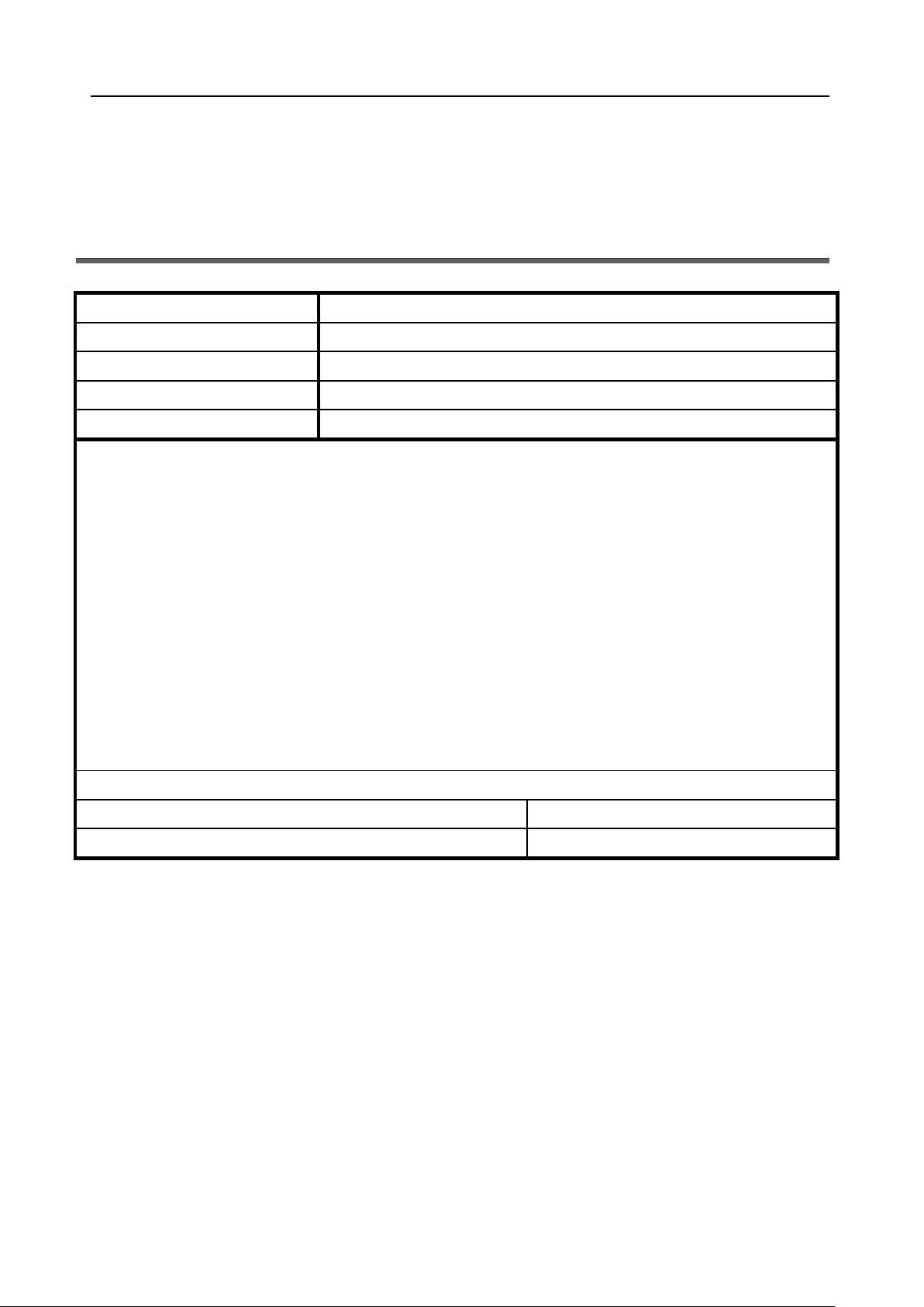
Appendix A: Trouble Report
Trouble Report Form
iv
Page 7
Comet 16xx Series User’s Manual
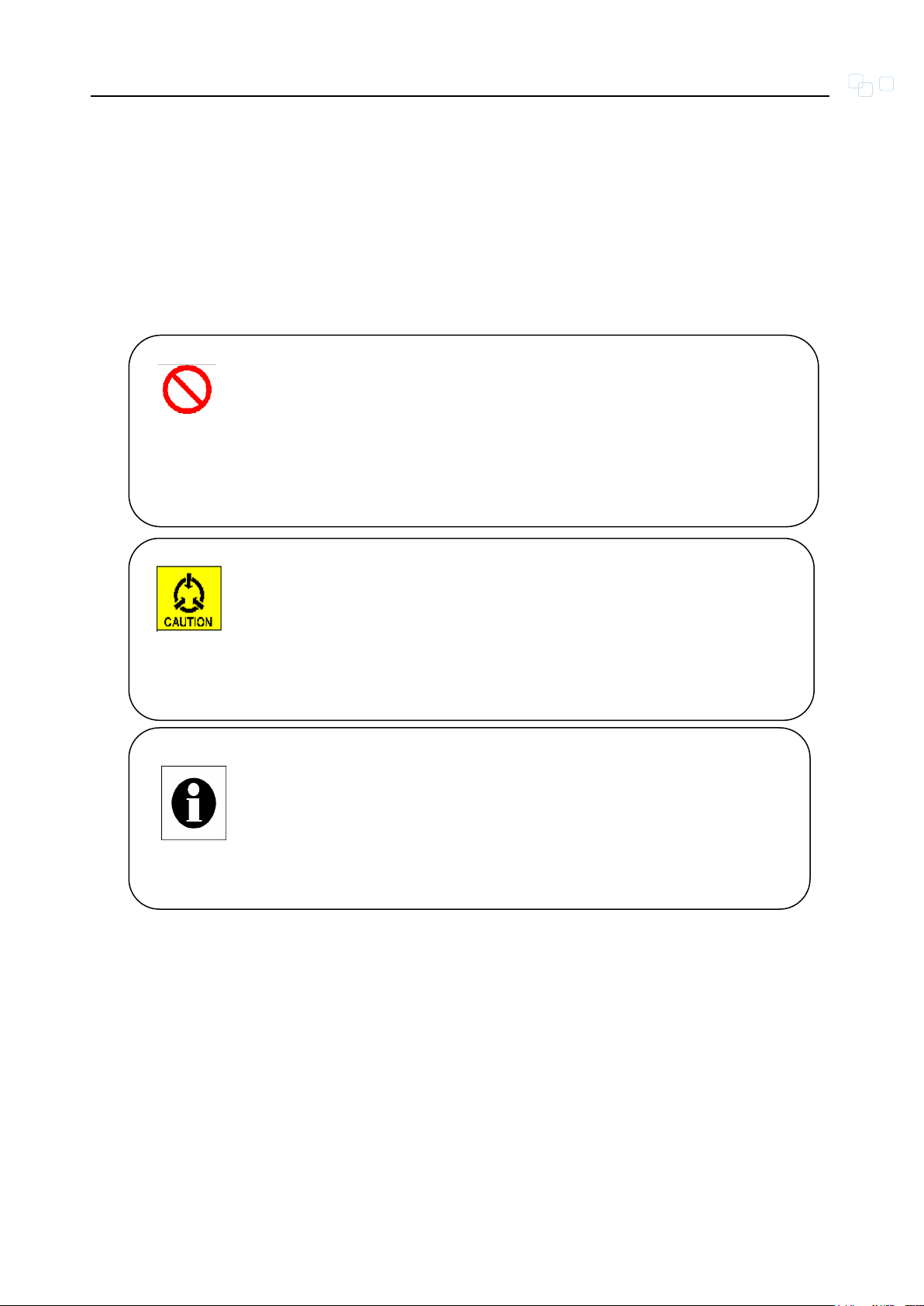
Warning:
This symbol and associated text are used when death or
injury to the user may result if operating instructions are not
followed properly.
Note:
This symbol and associated text are used to provide the
users with extra information that may be helpful when
following the main instructions in this manual.
Caution:
This symbol and associated text are used when damages to
the equipment or impact to the operation may result if
operating instructions are not followed properly.
Symbols Used in This Manual
3 types of symbols are used throughout this manual. These symbols are used to
advise the users when a special condition arises, such as a safety or operational
hazard, or to present extra information to the users. These symbols are explained
below:
v
Page 8

Comet 16xx Series User’s Manual
LIMITED WARRANTY
TAINET’s DISTRIBUTOR shall be responsible to its customers for any and all
warranties, which it makes relating to Products, and for ensuring that replacements
and other adjustments required in connection with the said warranties are satisfactory.
TAINET warrants to DISTRIBUTOR that the Products to be delivered hereunder will be
free of defects in material and workmanship under normal use and service for a period
of twenty-four (24) months [twelve (12) months in Taiwan] following the date of
shipment to DISTRIBUTOR.
If during the warranty period, any component part of the equipment becomes defective
by reason of material or workmanship, and DISTRIBUTOR notifies TAINET of such
defect within seven days after knowing of such defect, TAINET shall, for any Product
that TAINET agrees is defective, at its option, supply a replacement part, request
return of equipment to its plant for repair, or perform necessary repair at the
equipment’s location. At TAINET's option, DISTRIBUTOR shall destroy any Product
that TAINET agrees is defective and shall provide satisfactory proof of such
destruction to TAINET. TAINET is not responsible for Products damaged by misuse,
neglect, accident or improper installation, or if repairs or modifications were made by
persons other than TAINET’s own authorized service personnel, unless such repairs
by others were made with the written consent of TAINET.
THE ABOVE WARRANTY IS IN LIEU OF ALL OTHER WARRANTIES, EXPRESSED
OR IMPLIED. THERE ARE NO WARRANTIES THAT EXTEND BEYOND THE FACE
HEREOF, INCLUDING, BUT NOT LIMITED TO, WARRANTIES OF
MERCHANTABILITY AND FITNESS FOR A PARTICULAR PURPOSE, AND IN NO
EVENT SHALL TAINET BE LIABLE FOR CONSEQUENTIAL DAMAGES. If
DISTRIBUTOR extends to its customers any additional warranty with respect to
Products that is broader in scope than the warranty provided by TAINET,
DISTRIBUTOR shall be solely responsible for any and all liabilities, obligations and
damages resulting from the extension of such warranty.
TAINET shall not be liable to any person for any special or indirect damages, including,
but not limited to, lost profits, from any cause whatsoever arising from or in any way
connected with the manufacture, sale, handling, repair, maintenance or use of the
Products, and in no event shall TAINET’s liability exceed the purchase price of the
Products.
vi
Page 9

Comet 16xx Series User’s Manual
Software Products are provided “as is” and without warranty of any kind. TAINET
disclaims all warranties including the implied warranties of merchantability and fitness
for a particular purpose. TAINET shall not be liable for any loss of use, interruption of
business or indirect, special, incidental or consequential damages of any kind.
TAINET shall do its best to provide end users with Software updates during the
warranty period under this Agreement.
TAINET has not been notified of any intellectual property rights or others which may be
infringed by the Products or the promotion, marketing, sale (or resale), or servicing
thereof in the Territory, but TAINET makes NO WARRANTY, EXPRESS OR IMPLIED,
WITH RESPECT THERETO.
vii
Page 10

Comet 16xx Series User’s Manual
CONTENTS
CHAPTER 1. OVERVIEW ......................................................................................... 1
1.1 OVERVIEW ................................................................................................................................ 1
1.2 APPLICATIONS .......................................................................................................................... 1
CHAPTER 2. SPECIFICATION ............................................................................... 3
2.1 MAIN FEATURES ....................................................................................................................... 3
2.2 SHDSL INTERFACE .................................................................................................................. 4
2.2.1 E1 Interface ........................................................................................................................................ 4
2.2.2 V.35 Interface .................................................................................................................................... 5
2.3 NETWORK SIDE INTERFACE ...................................................................................................... 5
2.3.1 Ethernet Interface ............................................................................................................................... 5
2.4 OAM ........................................................................................................................................ 6
2.5 TECHNICAL SPECIFICATIONS..................................................................................................... 7
2.6 APPLICATIONS .......................................................................................................................... 8
2.6.1 EFM Application ............................................................................................................................... 8
2.6.2 TDM Application ............................................................................................................................... 9
CHAPTER 3. INTERFACES ................................................................................... 10
3.1 FRONT PANEL ......................................................................................................................... 10
3.1.1 Status Indicators ............................................................................................................................... 11
3.1.2 The RST Button ............................................................................................................................... 11
3.2 REAR PANEL ........................................................................................................................... 12
CHAPTER 4. INSTALLATION ............................................................................... 13
4.1 UNPACKING ............................................................................................................................ 13
CHAPTER 5. OPERATION OF WEB .................................................................... 14
5.1 OVERVIEW .............................................................................................................................. 14
5.2 LOGIN PAGE ............................................................................................................................ 14
5.3 STATUS ................................................................................................................................... 15
5.3.1 Local/Remote Status ........................................................................................................................ 15
5.3.2 Ethernet Statistics ............................................................................................................................ 19
5.4 CONFIGURATION ..................................................................................................................... 19
5.4.1 User Management ............................................................................................................................ 19
5.4.2 Local/Remote General Setup ........................................................................................................... 20
5.4.3 Trap Setup ........................................................................................................................................ 21
5.4.4 VLAN Setup .................................................................................................................................... 21
5.4.5 QoS Setup ........................................................................................................................................ 22
viii
Page 11

Comet 16xx Series User’s Manual
5.4.6 Load Local/Remote Profile .............................................................................................................. 22
5.4.7 Local/Remote Setting ...................................................................................................................... 23
5.5 MAINTENANCE ........................................................................................................................ 24
5.5.1 Alarm Log ........................................................................................................................................ 24
5.5.2 Performance History ........................................................................................................................ 25
5.5.3 Software Upgrade ............................................................................................................................ 26
5.5.4 Loopback Test .................................................................................................................................. 27
5.6 SAVE ....................................................................................................................................... 27
5.6.1 Local/Remote Save .......................................................................................................................... 27
5.7 EXAMPLES .............................................................................................................................. 28
5.7.1 E1 to E1 Connection ........................................................................................................................ 28
APPENDIX A PIN ASSIGNMENT .......................................................................... 29
APPENDIX B TROUBLE REPORT ........................................................................ 31
ix
Page 12

Comet 16xx Series User’s Manual
FIGURES
FIGURE 1-1 APPLICATION OF BACK-TO-BACK ................................................................................................. 2
FIGURE 1-2 POSSIBLE INTERFACE CONFIGURATION OF COMET SYSTEM ....................................................... 2
FIGURE 2-1 POINT TO POINT APPLICATION OF THE COMET 16XX SERIES WITH ETHERNET I/F ..................... 9
FIGURE 2-2 TDM APPLICATION OF THE COMET 16XX SERIES WITH E1, V35 OR FE I/F ................................ 9
FIGURE 3-1 FRONT PANEL OF THE COMET 16XX SERIES .............................................................................. 10
FIGURE 3-2 REAR PANEL OF THE COMET 16XX SERIES ................................................................................ 12
FIGURE 5-1 LOGIN PAGE ................................................................................................................................ 15
FIGURE 5-2 LANGUAGE SELECTION ............................................................................................................... 15
FIGURE 5-3 LOCAL STATUS .......................................................................................................................... 16
FIGURE 5-4 REMOTE STATUS ........................................................................................................................ 17
FIGURE 5-5 CURRENT ALARM ...................................................................................................................... 17
FIGURE 5-6 CURRENT PERFORMANCE .......................................................................................................... 18
FIGURE 5-7 LOOPBACK TEST STATUS .......................................................................................................... 18
FIGURE 5-8 ETHERNET STATISTICS .............................................................................................................. 19
FIGURE 5-9 USER MANAGEMENT ................................................................................................................. 19
FIGURE 5-10 LOCAL GENERAL SETUP ............................................................................................................ 20
FIGURE 5-11 REMOTE GENERAL SETUP ......................................................................................................... 20
FIGURE 5-12 TRAP SETUP............................................................................................................................... 21
FIGURE 5-13 PORT-BASE VLAN .................................................................................................................... 21
FIGURE 5-14 TAG VLAN ................................................................................................................................ 22
FIGURE 5-15 QOS BY PORT............................................................................................................................. 22
FIGURE 5-16 LOAD PROFILE........................................................................................................................... 23
FIGURE 5-17 LOCAL/REMOTE SETTING EFM MODE ...................................................................................... 24
FIGURE 5-18 LOCAL/REMOTE SETTING DBM MODE...................................................................................... 24
FIGURE 5-19 ALARM LOG .............................................................................................................................. 25
FIGURE 5-20 PERFORMANCE HISTORY .......................................................................................................... 25
FIGURE 5-21 SOFTWARE UPGRADE ................................................................................................................ 26
FIGURE 5-22 STEP 1 OF FIRMWARE UPGRADE ............................................................................................... 26
FIGURE 5-23 UPGRADING FIRMWARE ............................................................................................................ 26
FIGURE 5-24 LOOPBACK TEST ........................................................................................................................ 27
FIGURE 5-25 LOCAL SAVE .............................................................................................................................. 27
FIGURE 5-26 REMOTE SAVE ........................................................................................................................... 28
FIGURE 5-27 CO ............................................................................................................................................. 28
FIGURE 5-28 CPE ............................................................................................................................................ 28
FIGURE 5-29 E1 SETTING ................................................................................................................................ 28
FIGURE 5-30 DSL RJ-45 PIN ASSIGNMENT ..................................................................................................... 29
FIGURE 5-31 LAN RJ-45 PIN ASSIGNMENT ..................................................................................................... 29
x
Page 13

Comet 16xx Series User’s Manual
FIGURE 5-32 BALANCED E1 RJ-45 PIN ASSIGNMENT .................................................................................... 30
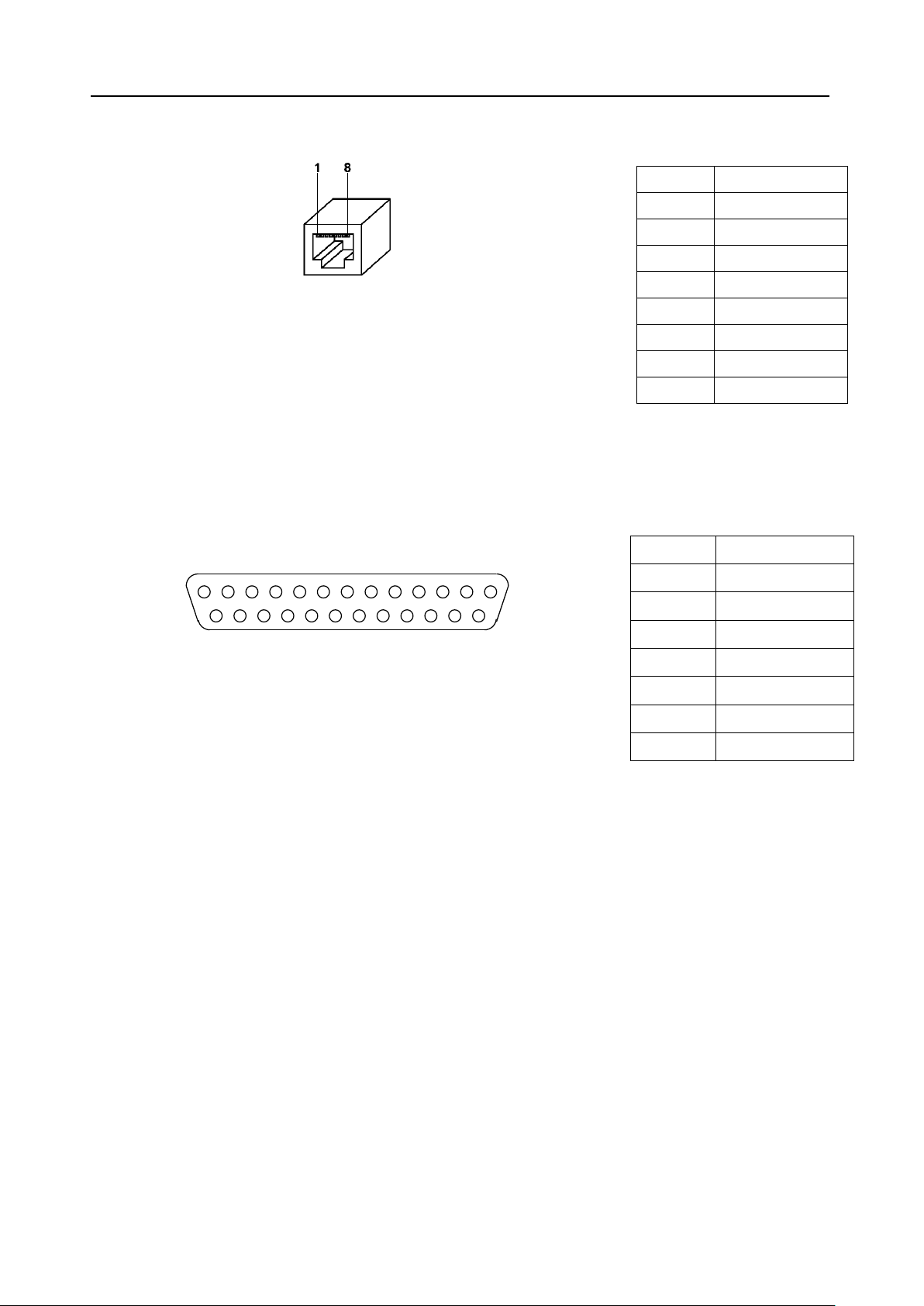
FIGURE 5-33 V.35 DB25 PIN ASSIGNMENT .................................................................................................... 30
xi
Page 14

Comet 16xx Series User’s Manual
TABLES
TABLE 2-1 TECHNICAL SPECIFICATIONS OF THE COMET 16XX SERIES ......................................................... 7
TABLE 3-1 INDICATORS ON FRONT PANEL ................................................................................................... 11
xii
Page 15

Comet 16xx Series User’s Manual
Chapter 1. Overview
This chapter begins with a general description of Comet 16xx Series. Then, the
chapter describes how to use TAINET Comet 16xx Series in several applications.
1.1 Overview
DSL (Digital Subscriber Loop) technologies increase the bandwidth capacity
of existing ubiquitous telephone line (the local copper loops). G.SHDSL is
designed for business applications, where high speed is required in both
transmission directions. It provides symmetrical data rates of 192Kbps to
5.696Mbps in 2-wire with a transmission distance up to 10Kft using SHDSL
technology. The data rates will be increased to 11.392Mbps in 4-wire link and
22.784Mbps in 8-wire link. The speed’s obtainable using DSL technologies
are tied to the distance between the customer premise and the Telco central
office. Performance varies with loop characteristics, such as line conditions,
loop distance, wire gauge, noise, and the number and locations of bridged
taps and gauge changes. The G.SHDSL bit rate can be configured (or rate
adapted) to adapt to the line conditions.
1.2 Applications
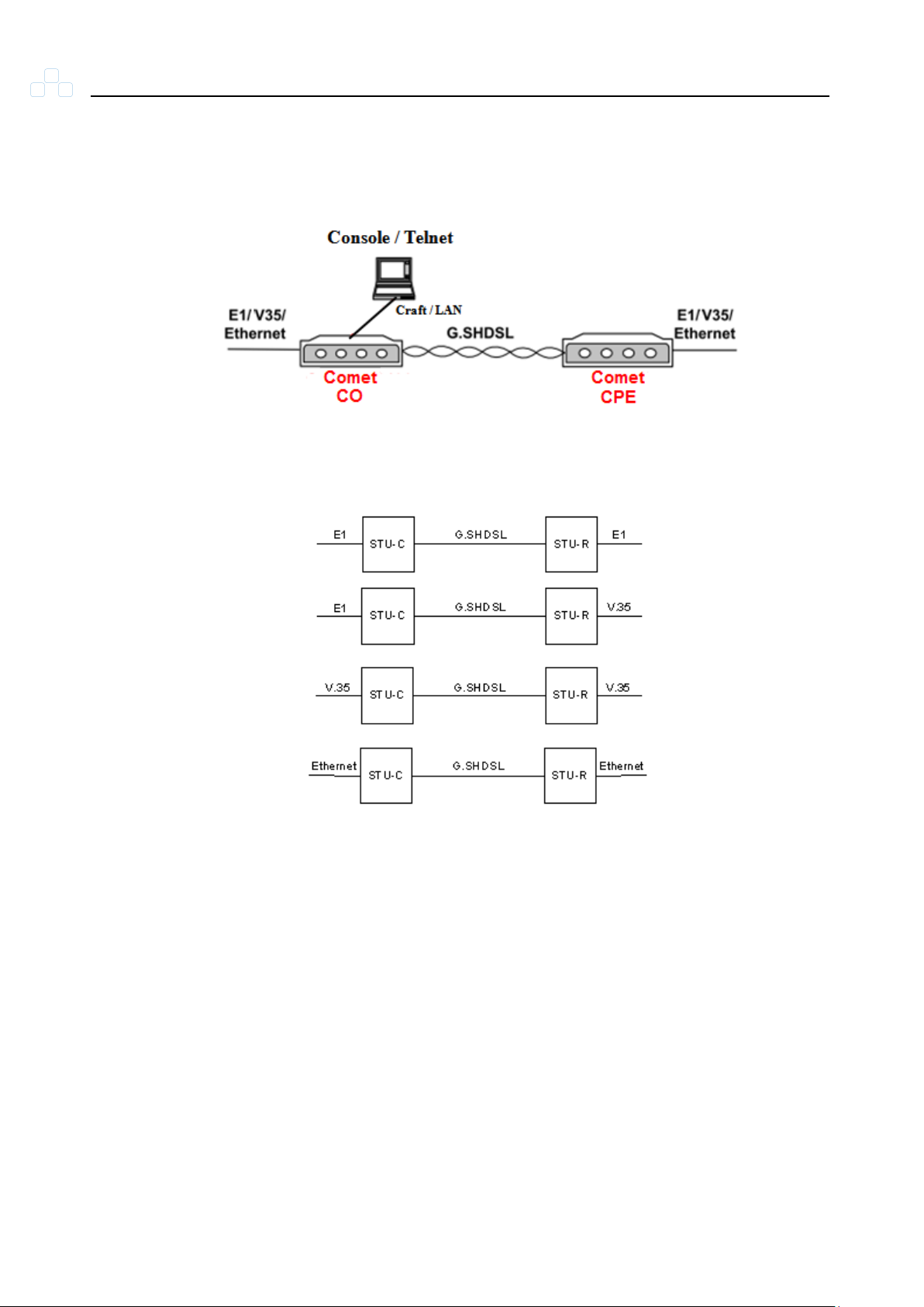
The SHDSL System consists of a central unit, CO (SHDSL Transceiver Unit Central), at central office, and a remote unit, CPE (SHDSL Transceiver Unit Remote), at customer premises.
1
The services are extended through the ubiquitous copper wires or leased
lines with the technologies of G.SHDSL. Various interface extensions are
supported on Comet: E1, DATA (V.35, V.36 / RS449, X.21, RS-530) and
Ethernet.
Figure 1-1 shows a typical application. Figure 1-2 depicts the possible
interface configurations. Comet automatically activates start-up when the
Page 16
Comet 16xx Series User’s Manual
power of the CO and CPE are enabled or after temporarily disconnecting the
CO or CPE.
Figure 1-1 Application of Back-to-back
2
Figure 1-2 Possible Interface Configuration of Comet System
Page 17

Comet 16xx Series User’s Manual
Chapter 2. Specification
To let the user understand the TAINET Comet Series, this chapter begins with its main
features. Then, the chapter continues to present SHDSL and SHDSL.bis interface, the
network side interface, timing and synchronization, OAM (Operation, Administration
and Maintenance) and technical specifications. The last part of this chapter is devoted
to the applications of TAINET Comet 16xx Series in different networks.
2.1 Main Features
Listed below are the main features of the Comet 16xx Series:
Listed below are the main features of the Comet 16xx Series.
Support loop interface G.SHDSL and G.SHDSL.bis.
Comet 16xx Series supports DTE interface: E1, DATA (V.35, X.21, RS-530,
V.36 / RS449) and Ethernet.
Carrying symmetrical 5.696 Mbps, 11.392Mbps, 22.784Mbps for up to 1.8
miles / 3 Km over 24-AWG single pair copper wire.
Carrying symmetrical 2048 Kbps payload for up to 2.4 miles / 3.9 Km over
26-AWG single pair copper wire.
Automatic line rate selection with Line Probe enabled.
Support SHDSL and SHDSL.bis payload rates of n ×64Kbps, where n is 3 to
89 in 2 wires, where n is 6 to 178 in 4 wires, where n is 12 to 356 in 8 wires.
Support Timing and Synchronization: Local (internal) timing, Line timing (loop
received clock).
3
For test and diagnostic purpose the Comet provides local and remote
loopback function.
Management by CID, Telnet and Web.
Remote control / monitoring via Telnet and Ethernet.
Remote in-band control / monitoring CPE via G.SHDSL EOC.
Page 18

Comet 16xx Series User’s Manual
Remote software upgrade via TFTP and Web.
Support security link function of G.SHDSL interface.
Comply with ITU-T G.991.2 and K.21.
2.2 SHDSL Interface
Meet ITU-T G.991.2 relative requirements.
Support Wetting Current function for feeding of a low current(between 1.0
mA and 20 mA)on the pair to mitigate the effect of corrosion of contacts.
Support power back off functions.
Modulation Method: 16-TCPAM, 32-TCPAM, 64-TCPAM and 128-TCPAM
(16/32/64/128 levels Trellis Coded Pulse Amplitude Modulation).
Physical Connection Type: Standard RJ-45 jack, 135 ohm balanced via 2
wires, 4 wires or 8 wires twisted pair.
Port enabled / disabled configurable.
Line Protection: meet ITU-T K.21 requirements.
2.2.1 E1 Interface
Comply with G.703 Standard.
Bit Rate: 2,048 Kbit / s 50 ppm.
Frame Format: Unstructured or Structured framing, field selectable.
Line Code: High Density Bipolar of Order 3 (HDB3).
Impedance: Normal 120 ohms 5% resistive, symmetrical pair.
Jitter performance: Meet ITU-T G.823 requirements.
4
Normal Peak Voltage of a Mark (pulse): 3 V for 120 ohms. Peak Voltage of a
Space (no pulse): 0 ± 0.3 V for 120 ohms.
Normal Pulse Width: 244 ns ± 25ns.
Ratio of the Amplitudes of Positive and Negative Pulse at the Center of Pulse
Interval: 0.95 to 1.05.
Page 19

Comet 16xx Series User’s Manual
Ratio of the Widths of Positive and Negative Pulse at the Normal Half
Amplitude: 0.95 to 1.05.
Line Interface: 120 ohm (RJ-45 / RJ48C) balanced, 75 ohm (BNC).
Physical Connection Type: Standard RJ-48C/RJ-45 jack (Balance) or BNC
(Unbalance).
Signal of input port was defined as above and can be modified by the
characteristics of the interconnecting pair. The insertion loss of this pair at a
frequency of 1024 kHz is in the range of 0 to 6 dB.
Minimum Return Loss at the Input Port: 12 dB for 51 to 102 kHz, 18 dB for
102 to 2,048 kHz 14 dB for 2,048 to 3,072 kHz.
2.2.2 V.35 Interface
Connector type: DB-25 female Connector with adapt cable convert to V.35/
V.11.
V.35, V.11 software selectable.
Line rate tolerance: 32 ppm.
Clock rate: n x 64K (n =1 to 72).
Clocking mode: DCE slave, DCE external (V.35/RS-530 only).
Clock inversion support.
Signal detect leads: DTR/ RTS.
2.3 Network Side Interface
2.3.1 Ethernet Interface
5
Provide a 10/100 Base-Tx auto sensing and half/full duplex configurable
Ethernet Interface.
Comply with the IEEE 802.3 / IEEE 802.3u
Physical Connection Type: Standard RJ-45 connector
Operate as a self-learning bridge specified in the IEEE 802.1d full protocol
transparent bridging function
Page 20

Comet 16xx Series User’s Manual
Supporting up to 2K(2048) MAC learning addresses
Supporting Bridge filter function based on source MAC addresses
Scalable Per Port Bandwidth Control (Step = 64K, up to 100M)
Support packet length up to 1518/1522/1536 byte
Support internal counter/PHY status output for management system
Support VLAN priority feature by Port-Based of packets for traffic and
management; Tag-Based is also supported
Support 802.3x Flow Control pause packet for Full Duplex in case buffer is
full
2.4 OAM
OAM (Operation, Administration and Maintenance) of the Comet 16xx Series
is listed below:
CID Console: command line operation
Web management message interface
Remote control / monitoring Comet 16xx Series via Telnet and Ethernet
Remote in-band control/monitoring CPE via G.SHDSL EOC
Remote Software Upgrade: Remotely via web interface with image file
selection; Locally CID console terminal with TFTP protocol
Configuration backup and restore to / from local nonvolatile memory
Support default configuration setup
Support Alarm Surveillance function
Support Performance Monitoring function
6
Page 21

Comet 16xx Series User’s Manual
DSL
Modulation
TC-PAM16/TC-PAM32/TC-PAM64/TC-PAM128
Mode
Full duplex with echo cancellation
Number of
loops
Single
Loop rate
N*64+8K(N=3~89) up to 5696Kbit/S (2 wire), (N=6~178)
11392Kbit/S (4 wire), (N=12~256) 22784Kbit/S (8 wire)
Loop
impedance
135 ohms
Clock
accuracy
± 32 ppm
Interface
Module
Data
V.35 Nx64 Kbps interface
RS-530 Nx64 Kbps interface
V.36 Nx64 Kbps interface
X.21 Nx64 Kbps interface
E1
E1 G703 / G704 interface
Ethernet
10/100Base-Tx Auto sensing
IEEE 802.3 / IEEE 802.3u
IEEE 802.1d full protocol transparent bridging function
Half and full duplex
Diagnostics
Loop test
E1 LDL : E1 Local Digital Loopback
V.35/V.11 LDL : V.35/V.11 Local Digital Loopback
E1 RDL : E1 Remote Digital Loopback
V.35/V.11 RDL : V.35/V.11 Remote Digital Loopback
Status
PWR
: Power indicator
2.5 Technical Specifications
Table 2-1 gives the technical specifications of the Comet 16xx Series.
Table 2-1 Technical Specifications of the Comet 16xx Series
7
Page 22

Comet 16xx Series User’s Manual
Indicators
DSL1-2
E1
V35
CPE
LAN
ALM
TST
: DSL status indicator
: E1 status indicator
: V.35 status indicator
: CPE or CO site indicator
: Ethernet link indicator
: Alarm indicator
: Test status indicator
Craft port
115200 BPS
8 bit data length
None parity
1 stop bit
9-pin/D-sub/female connector
Ethernet port
10/100M BPS
RJ-45 jack
Power Requirement
Input
DC 12V ± 5%, Load=1.0A
Power
Consumption
< 7 W
Environments
Temperature
Operating +0℃ ~ +45℃
Storage -10℃ ~ 70℃
Humidity
Operating 90% non-condensing
Storage 95% non-condensing
2.6 Applications
This section describes how to apply TAINET Comet 16xx Series in the
network systems.
2.6.1 EFM Application
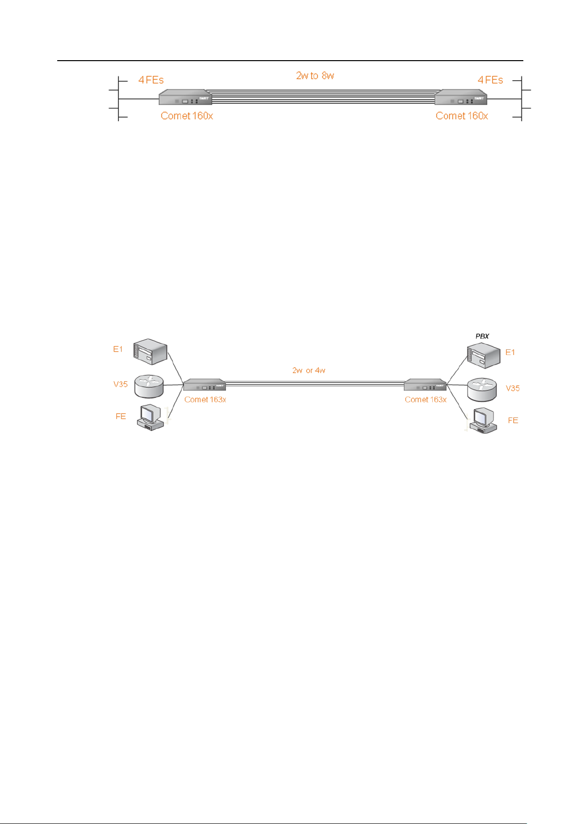
The Comet 16xx Series supports EFM applications. Figure 2-1 shows the
general Point To Point applications using two Comet 16xx Series. One unit is
configured as a central office site (CO) unit and the other is the customer
8
premise equipment (CPE) unit.
Page 23
Comet 16xx Series User’s Manual
Figure 2-1 Point To Point Application of the Comet 16xx Series with Ethernet
2.6.2 TDM Application
The Comet 16xx Series also supports TDM application. Figure 2-2 shows the
general TDM application where remote routers or PBX are interconnected via
two Comet 16xx Series. One unit is configured as a central office site (CO)
unit and the other is the customer premise equipment (CPE) unit.
I/F
Figure 2-2 TDM Application of the Comet 16xx Series with E1, V35 or FE I/F
9
Page 24
Comet 16xx Series User’s Manual
Chapter 3. Interfaces
In this chapter, we will focus our attention on the interfaces of the Comet 16xx Series.
First, the front panel of the Comet 16xx Series will be discussed. After that, we will
examine in more detail the rear panel of the Comet 16xx Series.
3.1 Front Panel
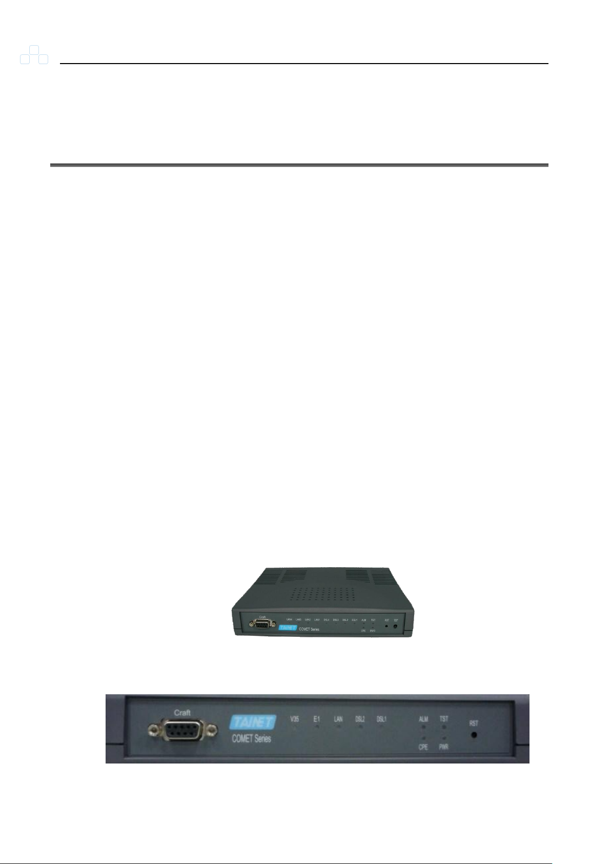
The front panel of Comet 16xx Series, as illustrated in Figure 3-1, contains
three main sections, Management port, status indicators and buttons. Via the
front panel of Comet 16xx Series, users can perform the functions as listed
below:
Displaying system status
Resetting the device and the alarm LED
Managing Comet 16xx Series via Craft port
From the status indicators of front panel, users can obtain useful information
to monitor the status of the Comet 16xx Series.
10
Comet 16xx Series
Figure 3-1 Front Panel of the Comet 16xx Series
Page 25

Comet 16xx Series User’s Manual
LED
GREEN
YELLOW
RED
Flashing
OFF
PWR
Power ON
Power OFF
TST
Testing
No Test
CPE
STU-R
STU-C
ALM
System Alarm occur
No Alarm
DSL1-2
DSL Link
DSL Alarm
DSL handshake
No Used
V35
In Service
V35 Alarm
Data tx/rx
No Used
E1
In Service
E1 Alarm
Data tx/rx
No Used
LAN
Ethernet Link
Full Duplex
Ethernet active
Link Down
3.1.1 Status Indicators
The status indicators of the Comet 16xx Series are depicted in Table 3-1.
There are nine LEDs, which are PWR, TST, CPE, ALM, DSL1, DSL2, V35,
E1 and LAN. These nine LEDs display the system status.
Table 3-1 Indicators on Front Panel
3.1.2 The RST Button
There is only one Reset button to manually reset the device.
11
Page 26
Comet 16xx Series User’s Manual
3.2 Rear Panel
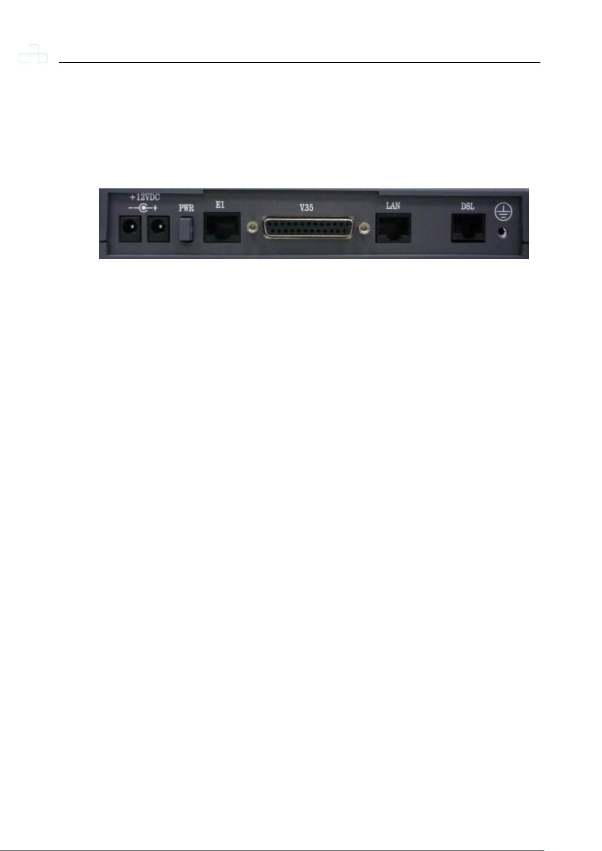
Figure 3-2 illustrates the rear panel of the Comet 16xx Series. Users may
connect the Comet 16xx Series to other devices or equipments via these
interfaces.
The following connectors/devices appear on the rear panel of the Comet
16xx Series.
Power On/Off: The Comet 16xx Series’ power switch
Figure 3-2 Rear Panel of the Comet 16xx Series
Power Receptacle: Redundant power for a DC power cable
E1 Interface: E1 / G.703 balanced interface (RJ-45)
LAN: Ethernet ports for RJ-45 connector
V.35 Interface: Data terminal equipment port
DSL Jack: RJ-45 jack for SHDSL link
12
Page 27

Comet 16xx Series User’s Manual
Chapter 4. Installation
In this chapter, we will present the installation guide for the Comet 16xx Series. It
begins with a checklist for unpacking the shipping package.
4.1 Unpacking
The Comet 16xx Series’ shipping package includes the following items:
Comet 16xx Series standalone unit
User’s manual CD Pack
AC to DC Power adapter
13
Page 28

Comet 16xx Series User’s Manual
Chapter 5. Operation of Web
In this chapter, you will be introduced to the Web operation of Comet 16xx Series. The
chapter starts with an overview of Comet 16xx Series’ Web. In addition, each main
menu item of the Comet 16xx Series’ Web, such as Configuration, Maintenance, and
Status will be discussed.
5.1 Overview
Please connect to the LAN port, the default management port on Comet 16xx
Series, and enter the IP address as the URL in the Internet browser. For
example, http://192.168.0.1 as mentioned to be the default IP address.
Comet 16xx Series supports the following Web browsers:
1. Internet Explorer 6+
2. FireFox 3+
3. Safari 4+
4. Chrome 4+
5.2 Login Page
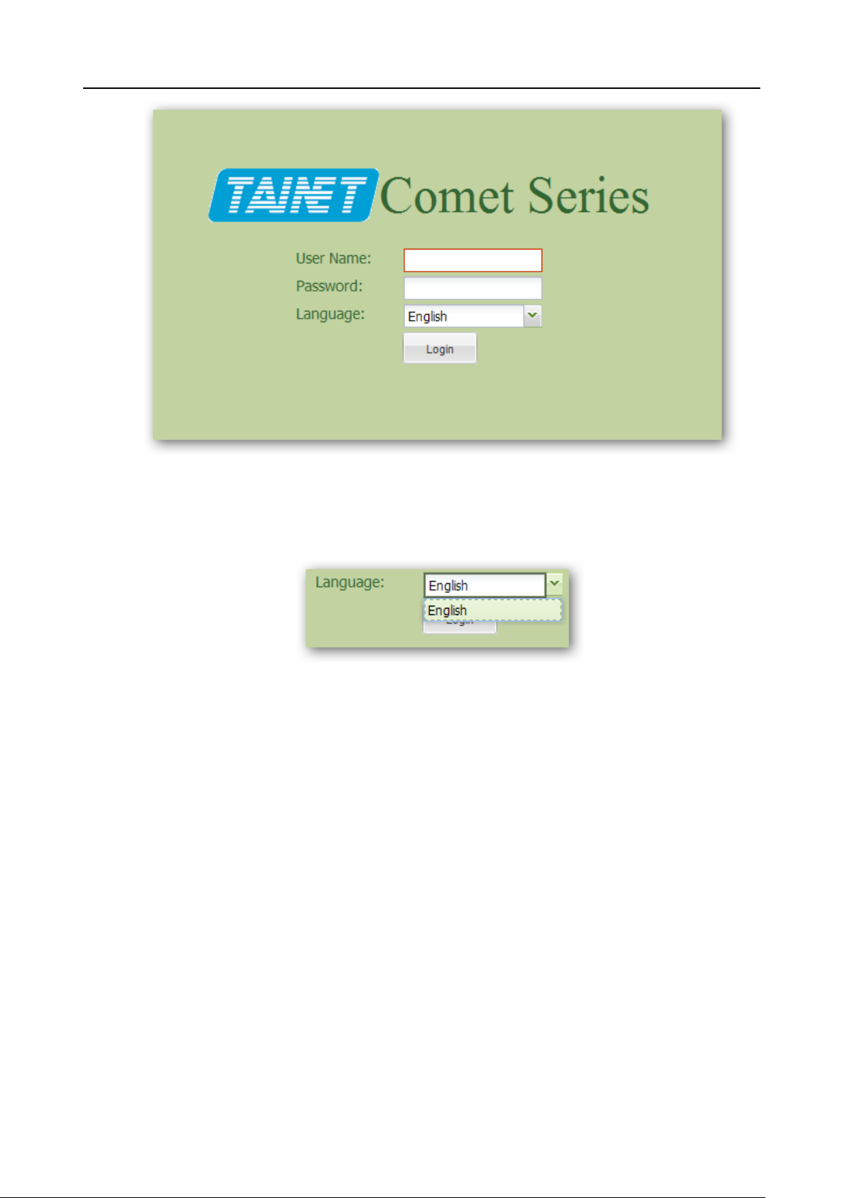
In this page, the user needs to enter correct name and password. There are
three built-in accounts with different privileges.
Administrator - username: admin, password: admin
14
User (Operator) - username: user, password: user
Guest (Monitoring) - username: guest, password: guest
Page 29
Comet 16xx Series User’s Manual
Figure 5-1 Login Page
Please use the following pull down menu option to select operation language.
5.3 Status
Local, remote and Ethernet status can be obtained in this section.
5.3.1 Local/Remote Status
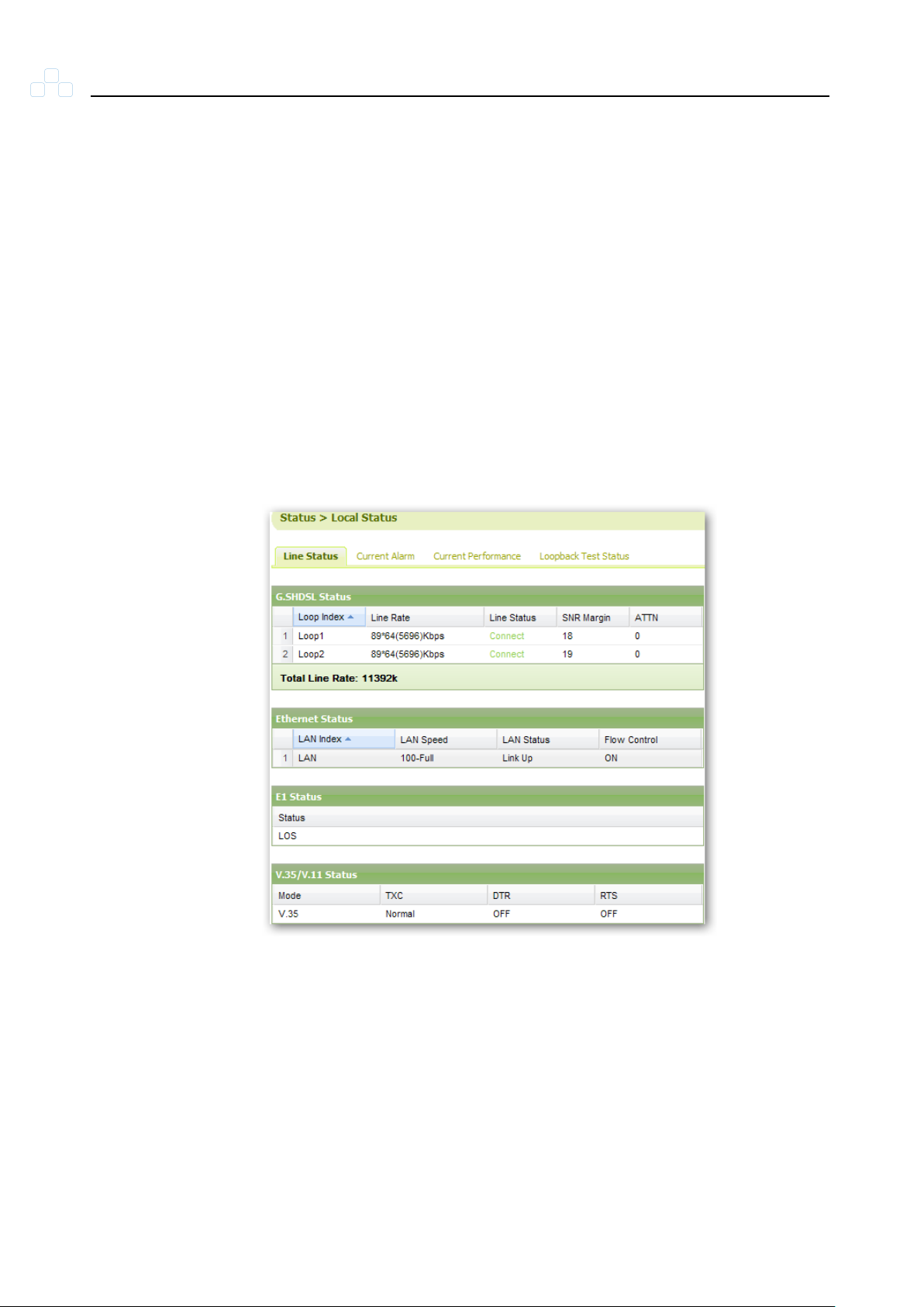
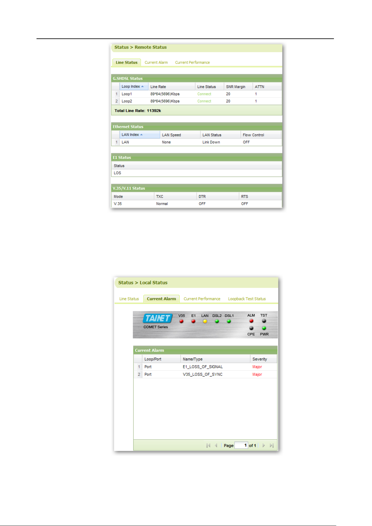
For 4-wire model, there are two loop indexes: loop 1 and loop 2. Thus, for
Figure 5-2 Language selection
15
2-wire model, only loop 1 is available. Comet 1608 supports up to 8-wire,
there will be loop 1~4 available in Comet 1608.
The following information is shown: Line Status, Current Alarm, Current
Performance, and Loopback Test Status (Only for CO side).
NOTE: For Comet 16xx Series 4-wire model, the total speed is the sum of
Page 30
Comet 16xx Series User’s Manual
Loop 1 Line Rate and Loop 2 Line Rate.
For example, if Loop 1 is 89*64k = 5696kbps, and Loop 2 is also 5696kbps.
The total speed of this device is 5696k + 5695k=11392kbps.
The following interface status is shown in Line Status: G.SHDSL Status,
Ethernet Status, E1 Status and V.35/V.11 Status.
G.SHDSL Status shows the following information: Loop Index, Line Rate, Line
Status, SNR (Signal Noise Ratio) Margin and ATTN.
Ethernet Status shows the following information: LAN Index, LAN Speed,
LAN Status and Flow Control.
V.35/V.11 Status shows the following information: Mode, TXC, DTR and RTS.
16
Figure 5-3 Local Status
Page 31
Comet 16xx Series User’s Manual
Figure 5-4 Remote Status
Current Alarm shows the following information: Loop/Port, Name/Type and
Severity.
17
Figure 5-5 Current Alarm
Page 32
Comet 16xx Series User’s Manual
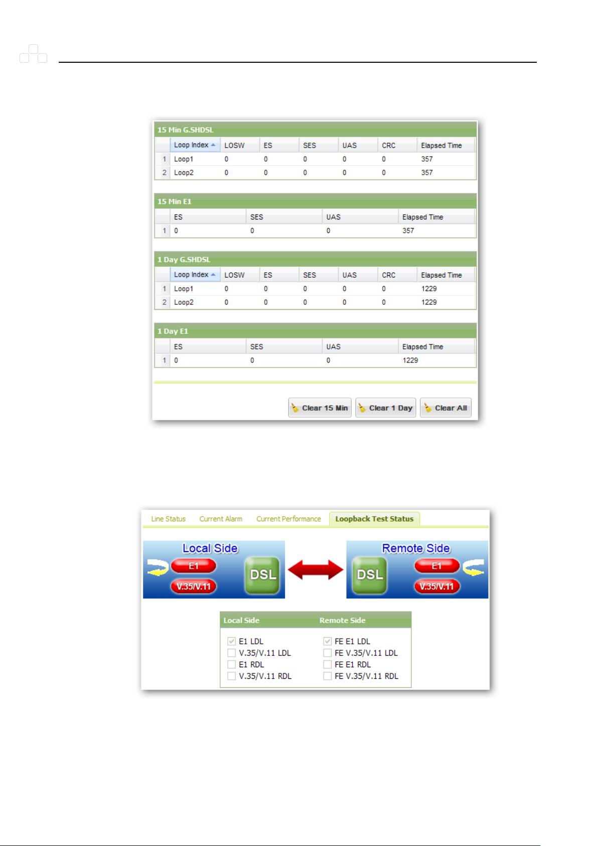
Current Performance shows the current performance error of G.SHDSL and
E1 in 15 minutes and 1 day duration.
Figure 5-6 Current Performance
Loopback Test Status shows the type of loopback test currently being used.
18
Figure 5-7 Loopback Test Status
Page 33
Comet 16xx Series User’s Manual
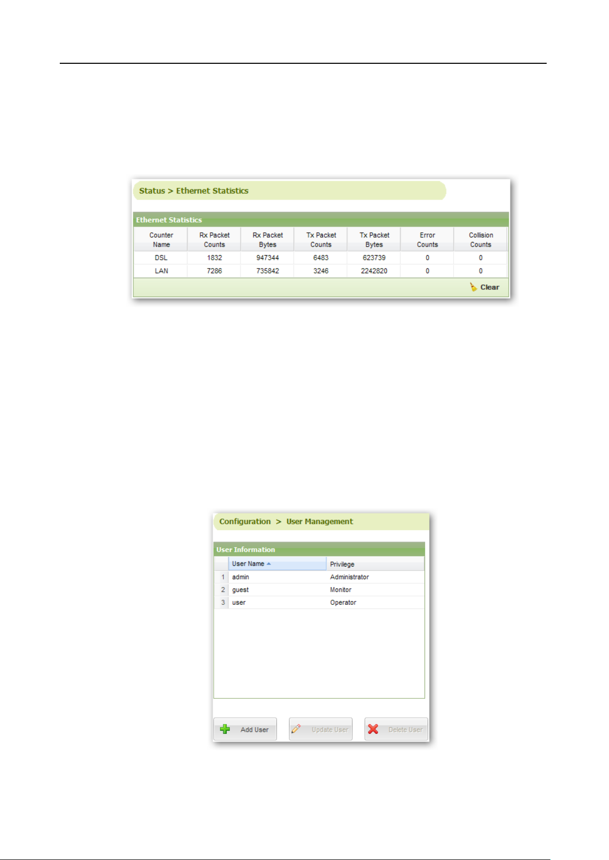
5.3.2 Ethernet Statistics
The following information is displayed: Counter Name, Rx Packet Counts, Rx
Packet Bytes, Tx Packet Counts, Tx Packet Bytes, Error Counts and Collision
Counts.
Figure 5-8 Ethernet Statistics
5.4 Configuration
5.4.1 User Management
There are three built-in users in Comet 16xx Series: Admin, Guest and User.
The user can add, delete, and update user’s name and password.
19
Figure 5-9 User Management
Page 34
Comet 16xx Series User’s Manual
5.4.2 Local/Remote General Setup
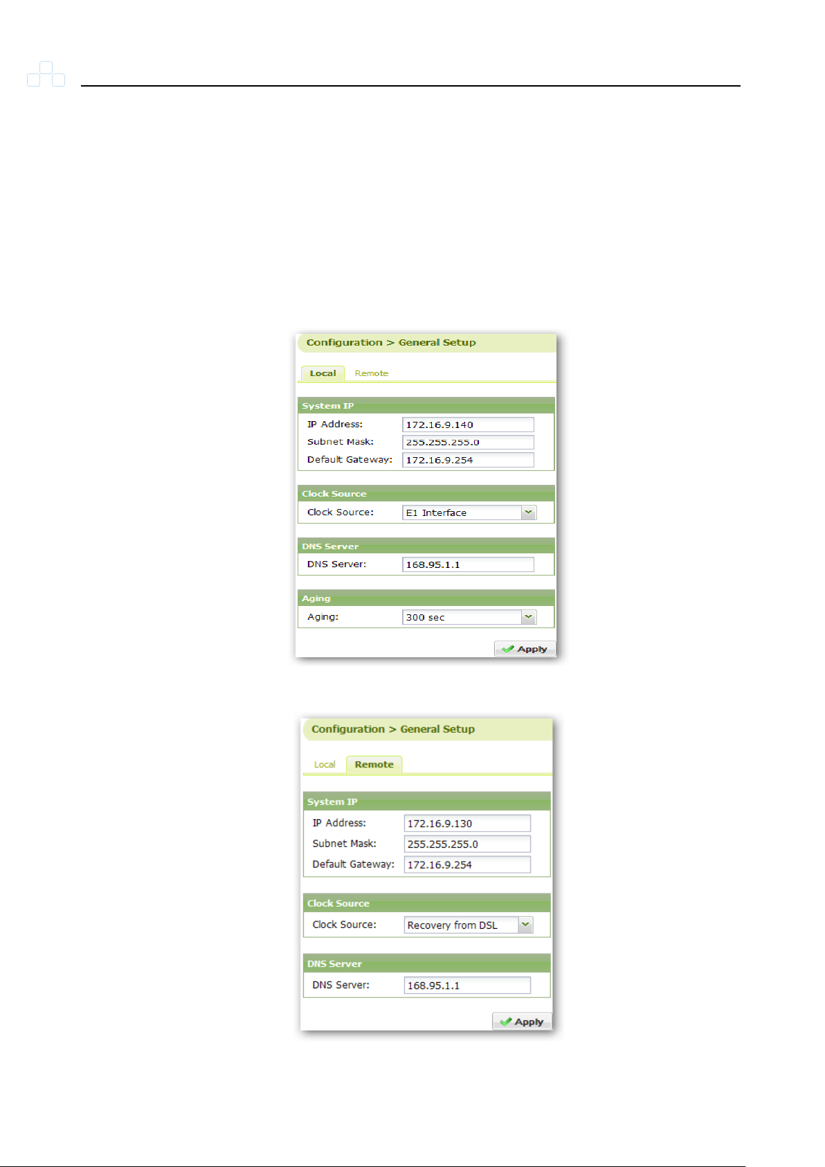
Users can set up the system IP, Clock Source, DNS Server and Aging time
(only for CO side). There are four clock sources available for the user to
select: Internal, E1 Interface, V.35/V.11 and Recovery from DSL. The default
clock source is Recovery from DSL. User can also set up the time to release
a MAC (Aging time) at: 1 sec, 18 sec, 75 sec or 300 sec. The default aging
time is 300 sec. Comet 16xx Series also allows the user to set up the IP
address of CPE from CO.
Figure 5-10 Local General Setup
Figure 5-11 Remote General Setup
20
Page 35
Comet 16xx Series User’s Manual
5.4.3 Trap Setup
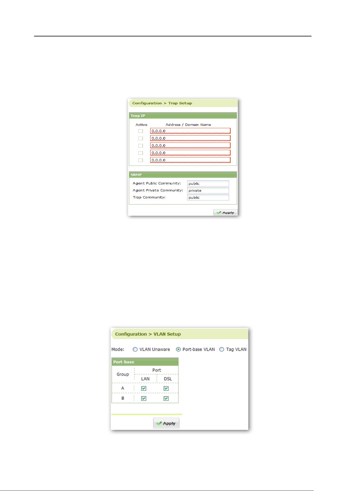
The TrapIP Address can be configured here. There are five sets of TrapIP
Address available. If DNS Server is set in General Setup, users can enter the
domain name instead of IP address.
5.4.4 VLAN Setup
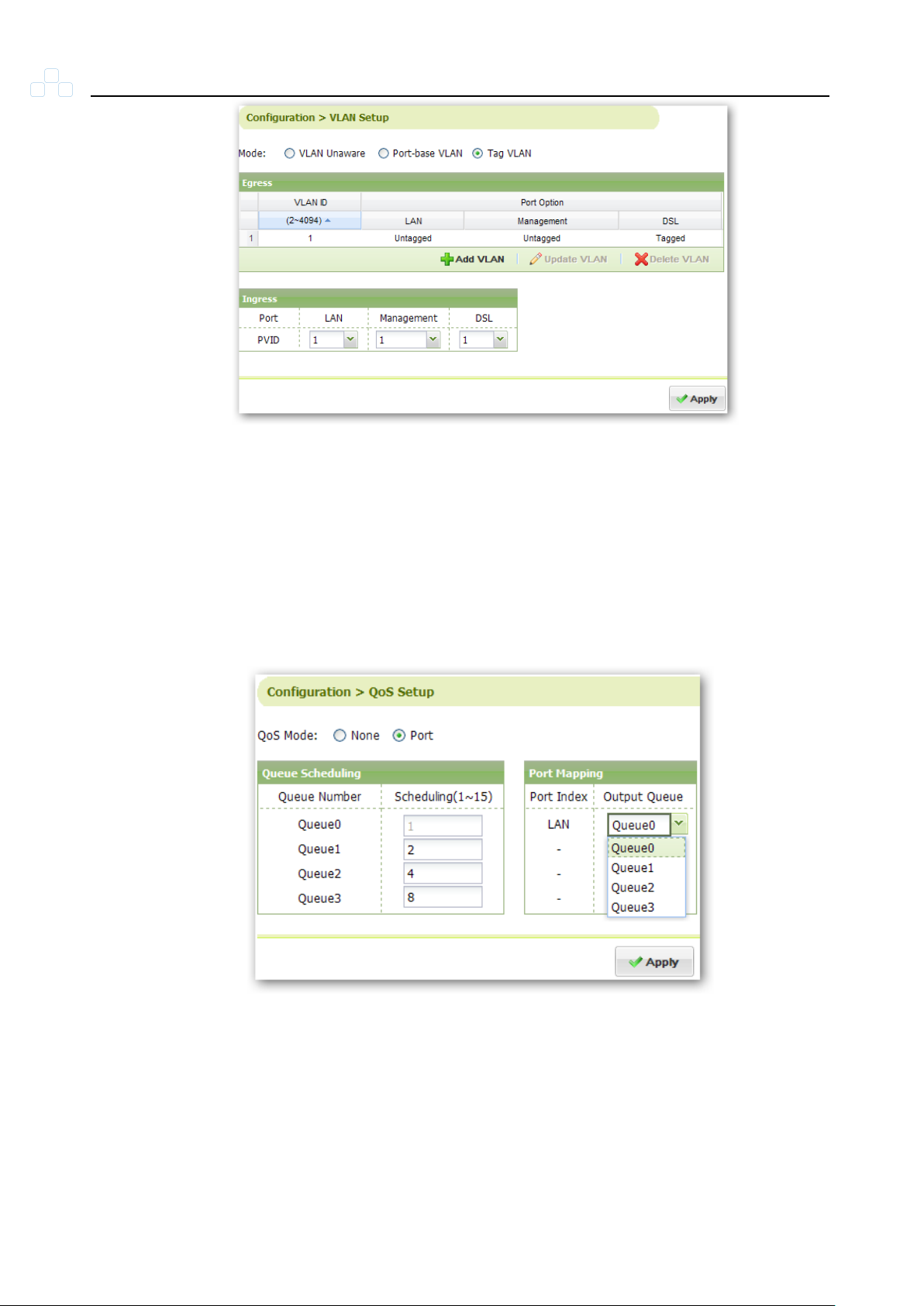
There are two modes of VLAN available on Comet 16xx Series: Port-base
and Tag VLAN. In Tag VLAN, user can define his own VLAN table by adding,
updating or deleting the VLAN tags. Once the Tag VLAN is enabled, only
traffic with tags in the VLAN table will be allowed to enter Comet 16xx Series.
Figure 5-12 Trap Setup
21
Figure 5-13 Port-base VLAN
Page 36
Comet 16xx Series User’s Manual
5.4.5 QoS Setup
Figure 5-14 Tag VLAN
Comet 16xx Series supports QoS by port. There are four queues available for
the user to define. User can set up the scheduling weight ranging from 1~15,
the scheduling weight of queue0 is always 1.
Figure 5-15 QoS by port
5.4.6 Load Local/Remote Profile
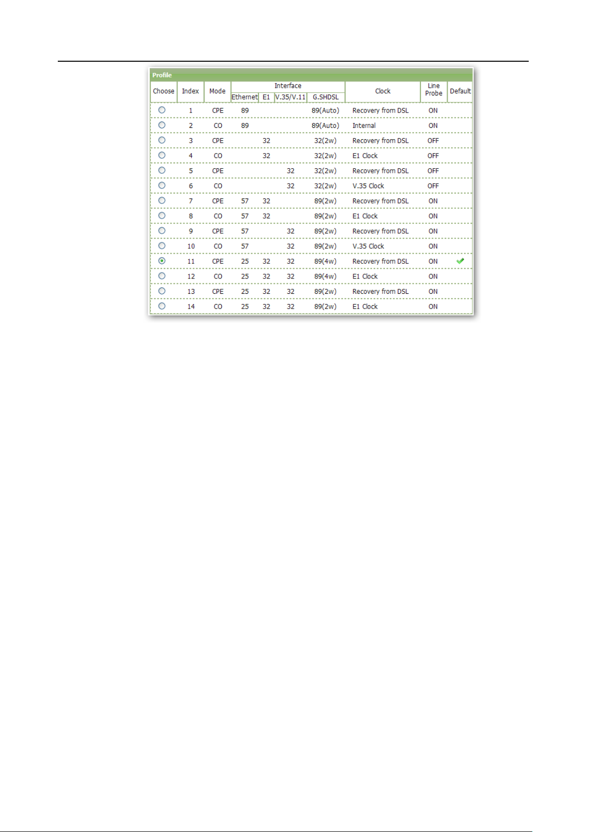
There are fourteen default profiles for the user to select. As shown in Figure
5-16, user can select CO or CPE with same settings. The default setting is
profile 11 and the corresponding profile is profile 12.
22
Page 37
Comet 16xx Series User’s Manual
5.4.7 Local/Remote Setting
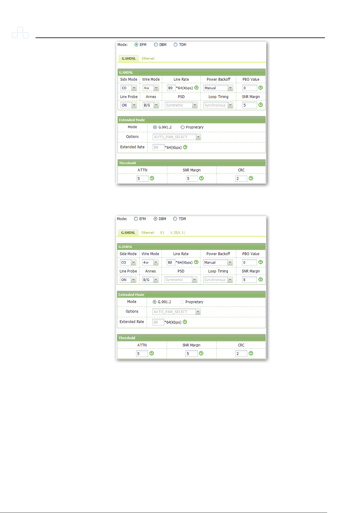
There are three modes to be selected by the users: EFM, DBM and TDM. In
EFM mode, user can only modify the settings of G.SHDSL and Ethernet. E1
and V.35/V.11 modification will be available in DBM and TDM mode.
Line Probe: When it is set to ON, the device adjusts the DSL line data rate
automatically according to (SNR Margin value). The DSL line quality is
represented by SNR (Signal Noise Ratio) value, the higher the SNR value,
the better the DSL line quality. When SNR value is very low, the DSL line
might become disconnected.
SNR Margin: If the actual SNR value is lower than SNR margin value, the
device will decrease the data rate to prevent SNR value from dropping so the
DSL link is up.
Figure 5-16 Load Profile
23
However, users should aware of that there is a relationship between the data
rate and connection distance. When the DSL line data rate goes higher, the
DSL line connection distance becomes shorter and vice versa.
Page 38
Comet 16xx Series User’s Manual
Figure 5-17 Local/Remote setting EFM mode
5.5 Maintenance
5.5.1 Alarm Log
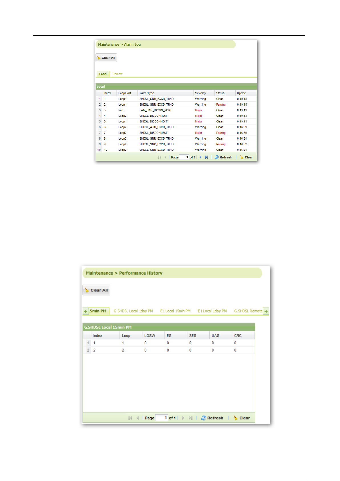
The alarm history is dispalyed in this section. The user can manually refresh
or clear the alarm log.
24
Figure 5-18 Local/Remote setting DBM mode
Page 39
Comet 16xx Series User’s Manual
Figure 5-19 Alarm Log
5.5.2 Performance History
The performance history shows the errors that may occur on each loop
during the 15 minutes and 1 day duration. Comet 16xx Series provides local /
remote G.SHDSL and E1 performance history. The user can manually refresh
or clear the performance history.
25
Figure 5-20 Performance History
Page 40
Comet 16xx Series User’s Manual
5.5.3 Software Upgrade
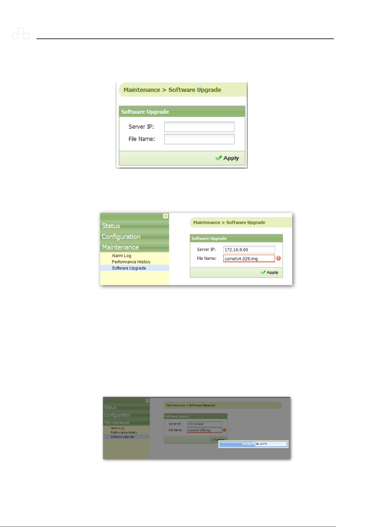
The local device can be upgraded using a TFTP server.
Step 1: Input Server IP address and firmware file name.
Figure 5-21 Software Upgrade
Figure 5-22 Step 1 of Firmware Upgrade
Step 2: Delete all Temporary Internet files including Cookies.
IE Browser : Tools >> Internet Options >> General >> Delete Cookie, Delete
Files
Step 3: Select “Apply” to start firmware upgrade.
26
Figure 5-23 Upgrading Firmware
Page 41
Comet 16xx Series User’s Manual
After firmware upgrade complete, device will automatically reboot and return
to the login page.
5.5.4 Loopback Test
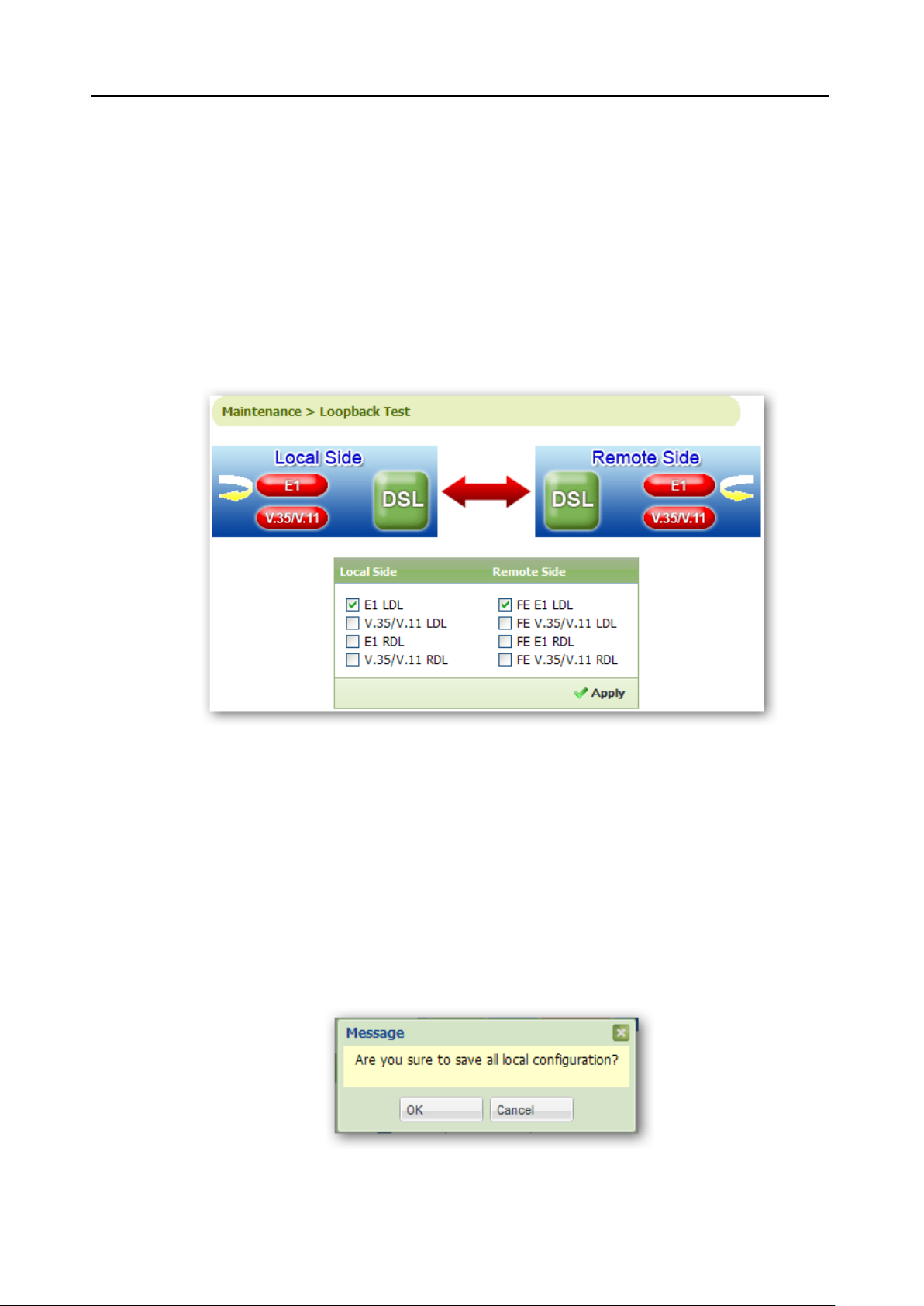
Comet 16xx Series provides eight types of loopback test modes: E1 LDL,
V.35/V.11 LDL, E1 RDL, V.35/V.11 RDL, FE E1 LDL, FE V.35/V.11 LDL, FE
E1 RDL and FE V.35/V.11 RDL. Comet 16xx Series supports multiple
loopback tests to be implemented concurrently.
5.6 Save
5.6.1 Local/Remote Save
Save all local/remote configurations.
Figure 5-24 Loopback Test
27
Figure 5-25 Local Save
Page 42
Comet 16xx Series User’s Manual
Figure 5-26 Remote Save
5.7 Examples
5.7.1 E1 to E1 Connection
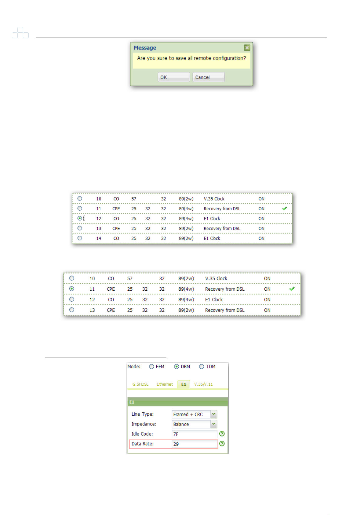
Select profile index 12 for CO, profile index 11 for CPE.
Figure 5-28 CPE
Input the desired data rate.
Configuration >> Local Setting >> E1
Figure 5-27 CO
28
Figure 5-29 E1 Setting
Page 43
Comet 16xx Series User’s Manual
Pin
8W
4W
2W 1 Tip(2)-
2
Ring(2)-
3
Tip(4)-
Tip(2)
4
Tip(1)-
Tip(1)
Tip 5 Ring(1)-
Ring(1)
Ring
6
Ring(4)-
Ring(2)
7
Tip(3)-
8
Ring(3)-
Pin
Description
1
TD+
2
TD -
3
RD+
4
NC
5
NC 6 RD -
7
NC
8
NC
Appendix A Pin Assignment
5.7.1.1 DSL RJ-45 Pin Assignment
Figure 5-30 DSL RJ-45 Pin
Assignment
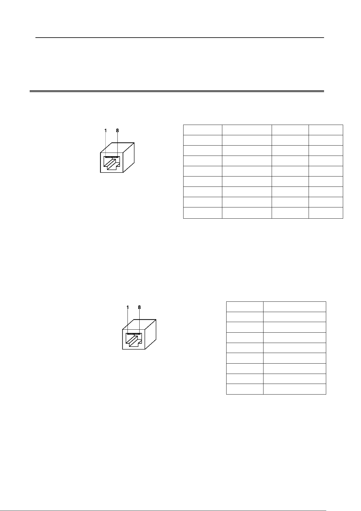
The pin assignment of G.SHDSL line is shown in Figure 5-30. The Comet 16xx Series
supports LAN interface port as shown in Figure 5-31.
5.7.1.2 LAN RJ-45 Pin Assignment
Figure 5-31 LAN RJ-45 Pin Assignment
29
Page 44
Comet 16xx Series User’s Manual
14 15 16 17 22 23 24 2518 19 20 21
1 2 3 4 5 6 10 11 12 137 8 9
Pin
Description
1
RX_ring
2
RX_tip
3
NC
4
Tx_ring
5
Tx_tip
6
NC
7
NC
8
NC
Pin
Description
1
FG
7
SG
4
RTS
5
CTS
6
DSR
8
DCD
20
DTR
5.7.1.3 G.703 / E1 RJ-45 Pin Assignment
Figure 5-32 Balanced E1 RJ-45 Pin Assignment
5.7.1.4 V.35 Pin Assignment
Figure 5-33 V.35 DB25 Pin Assignment
30
Page 45
Comet 16xx Series User’s Manual
Company
Local Representation
Purchase Order No
Equipment Serial No
Software Version
Please describe: 1. Testing Network Structure 2. Configuration
3. Testing Network Equipment 4. Trouble Description
E-MAIL:
TEL:
FAX:
Signature:
Date: / /
Appendix B Trouble Report
31
 Loading...