

Page 1

D E C 0 0 5 / 0 4
TAILIFT LTD. 2006
RADIAL DRILLS
TPR1230 TPR1230H
TPR1600H TPR2000H
Operation Manual
Page 2

0-1
Section Content page
CHAPTER 1 Safety Guidelines
1.1 Please follow the below basic safety principles ………………………..
1-1
1.2 Precautions for the transportation and installation ……………………..
1-1
1.3 Precautions for operation ……………………………………………..
1-1
1.4 Precautions for checking and maintenance ……………………………..
1-2
1.5 Warning labels on the machine ………………………………………….
1-3
1.5.1 Warning labels and mark introduction………………………………………..
1-3
1.5.2 Labels ……………………………………………………………………….
1-4
CHAPTER 2 General specifications
2.1 The anticipated machine life …………………………………………….
2-1
2.2 Machine dimensions …………………………………………………….
2-1
2.3 The machine ………………………………………………………………….
2-2
2.3.1 Description ………………………………………………………………….
2-2
2.3.2 Parts ………………………………………………………………………….
2-2
2.4 Specifications ………………………………………………………………...
2-3
2.4.1 TPR-1230H Specification ………………………………………………..
2-3
2.4.2 TPR-1230 Specification ………………………………………………..
2-4
2.4.3 TPR-1600H Specification ………………………………………………..
2-5
2.4.4 TPR-2000H Specification ………………………………………….
2-6
2.5 Standard and Option Accessories ………………………………………….
2-7
2.6 Operation position and noise level …. ……………………………………...
2-7
2.6.1 Operation position ……………………………………………………..
2-7
2.6.2 The noise level …………………………………………………………….
2-7
CHAPTER 3 Preparation to install
3.1 Space and room requirement ……………………………………………..
3-1
3.1.1 Floor requirement …………………………………………………………
3-1
3.1.2 Space requirement …………………………………………………………
3-3
3.2 Environment requirement ………………………………………………
3-3
3.3 Power supply requirement ………………………………………………
3-4
3.4 Electric system alculation ………………………………………………
3-5
CHAPTER 4 Transportation and Installation
4.1 Disassembly and packaging …………………………………………….
4-1
4.1.1 General ……………………………………………………………….……
4-1
4.1.2 Packaging ………………………………………………………………….
4-1
4.2 Transportation ……………………………………………………………...
4-2
4.2.1 The diagram of the machine weight and its gravity center …………….
4-2
Page 3

0-2
Section Content page
4.2.2 The movement of the machine …………………………………………
4-2
4.2.3 The order to pack …………………………………………………………...
4-3
4.3 Installation of the machine ………………………………………………
4-3
4.3.1 Have the machine set onto the fastening bolts of the crate base ……….
4-3
4.3.2 Level adjusting. …………………………………………………………….
4-4
4.3.3 The installation of the electricity ………………………………………
4-4
4.4 The test after installation ………………………………………
4-4
4.5 The procedure for dismantling the machine …………………………..
4-4
CHAPTER 5 Operation
5.1 A brief introduction to the relevant operation hardware ……………….
5-1
5.1.1 (For TPR-1230, TPR-1230H) ………………………………………..
5-1
5.1.2 (For TPR-1600H, TPR-2000H) ……………………………………...
5-3
5.1.3 Safty protective device (suit every model)…………………………….…….
5-5
5.2 Instruction to switches …………………………………………………..
5-6
5.2.1 (For TPR-1230, TPR-1230H) …………………………………………
5-6
5.2.2 (For TPR-1600H, TPR-2000H) …………………………………………
5-8
5.3
Installation of the clamp(work piece)
……………………………….
5-9
5.3.1 General …………………………………………………………………….
5-9
5.3.2 Introduction of the vise and the clamping of the work piece …………
5-9
5.3.3 Universal clamp and the clamping of the work piece ………………..
5-10
5.4 Installation and change of the drilling bit ……………………………
5-11
5.4.1 The assembly and disassembly of the drilling head and clamp ………
5-11
5.4.2 The assembly and disassembly of the straight handle drill bit ………..
5-13
5.5 Power on and off …………………………………………………………...
5-13
5.5.1 Power on …………………………………………………………………...
5-13
5.5.2 Power off …………………………………………………………………...
5-13
5.6 Work light ………………………………………………………………….
5-14
5.7 Cutting fluids ……………………………………………………………...
5-14
5.8 Elevating the arm …………………………………………………………...
5-14
5.9 Rotate the Gearbox right or leftwards …………………………………
5-15
5.9.1
(For TPR-1230,TPR-1230H)
…………………………………..
5-15
5.9.2
For TPR-1600H, TPR-2000H)
………………………………………
5-15
5.10 Rotate the arm forward or backwards …………………………………
5-16
5.10.1 (For TPR-1230,TPR-1230H)………………………………………………..
5-16
5.10.2 (For TPR-1600H, TPR-2000H)……………………………………………...
5-16
5.11 Change the spindle speed ……………………………………………….
5-17
5.11.1 (For TPR-1230,TPR-1230H) ………………………………………
5-17
5.11.2 (For TPR-1600H, TPR-2000H) ………………………………………
5-20
Page 4

0-3
Section Content page
5.12 Automatic Feed …………………………………………………………….
5-22
5.12.1
(For TPR-1230, TPR-1230H)
…………………………………………
5-22
5.12.2
(For TPR-1600H, TPR-2000H)
……………………………………..
5-24
5.13 The spindle ………………………………………………………………...
5-25
5.14 Threading …………………………………………………………………..
5-25
5.15 The assembly and disassembly of the work table ……………………..
5-25
5.16 Cutting fluids for all kinds of material …………………………………
5-26
CHAPTER 6 Adjustment
6.1 General …………………………………………………………………….
6-1
6.2 The arm clamping lever …………………………………………………
6-1
6.2.1 (For TPR-1230, TPR-1230H) …………………………………………
6-1
6.2.2 (For TPR-1600H, TPR-2000H) …………………………………………
6-2
6.3 Adjust tighten the clamping device ……………………………………
6-3
6.3.1 (For TPR-1230, TPR-1230H) ……………………………………
6-3
6.3.2 (For TPR-1600H, TPR-2000H) ……………………………………….
6-3
6.4 Adjust tighten the clamping device ……………………………………
6-4
6.4.1 (For TPR-1230, TPR-1230H) ……………………………………
6-4
6.4.2 (For TPR-1600H, TPR-2000H) …………………………………………..
6-5
6.5 Adjustment for the backlash between the gearbox and the arm rail………...
6-6
6.6 Adjustment of the hydraulic pressure ……………………………….…
6-6
6.7 Adjustment of the clutch(for TPR-1600H,TPR-2000H)…………………….
6-7
CHAPTER 7 Maintenance
7.1 General …………………………………………………………………….
7-1
7.2 Daily Maintenance …………………………………………………………
7-1
7.2.1 Clearing …………………………………………………………………….
7-1
7.2.2 Please clean every parts using a metal brush and a rag, dipped with oil, to
rub them …………………………………………………………….………
7-1
7.2.3 The way to clean iron filings ……………………………………………
7-2
7.2.4 Lubrication ………………………………………………………………….
7-2
7.2.5 Change oil inside of the speed reduction of the arm elevating motor……….
7-3
7.2.6 Chang the oil inside the gearbox ………………………………………
7-4
7.2.7 Changing hydraulic oil in the hydraulic oil pump…………………………..
7-5
7.3 Replace the cutting fluids ………………………………………………
7-6
7.4 Maintenance and replacement period ………………………………….
7-6
7.5 Waste disposition …………………………………………………………...
7-6
Page 5

0-4
Section Content page
CHAPTER 8 Troubleshooting
8.1 The spindle overloads and the relay jumps …………………………….
8-1
8.1.1 The cause …………………………………………………………………...
8-1
8.1.2 The solution ………………………………………………………………...
8-1
8.2 The spindle overloads and the fuse burns out ………………………….
8-1
8.2.1 The cause …………………………………………………………….……
8-1
8.2.2 The solution ………………………………………………………………...
8-1
8.3
What if the drill bit get broken?
……………………………………….
8-2
8.4 What if the screw tap get broken? ……………………………………...
8-2
8.5 How if a person is entangled? ………………………………………….
8-2
CHAPTER 9 Annex
9.1 Electrical circuit diagram (For TPR-1230H CE Standard)………………..
9-1
9.2 Electrical circuit diagram (For TPR-1230 CE Standard)…………….……
9-2
9.3 Electrical circuit diagram (For TPR-1600H CE Standard)………………..
9-3
9.4 Electrical circuit diagram (For TPR-2000H CE Standard)………………..
9-4
9.5 Electrical main parts list (For TPR-1230H CE Standard)…………………
9-5
9.6 Electrical main parts list (For TPR-1230 CE Standard)……………..…….
9-7
9.7 Electrical main parts list (For TPR-1600H CE Standard)…………………
9-9
9.8 Electrical main parts list (For TPR-2000H CE Standard)…………………
9-11
9.9 Electrical circuit diagram (For TPR-1230 Standard)……………….……..
9-13
9.10 Electrical circuit diagram (For TPR-1230 H Standard)…………………...
9-14
9.11 Electrical circuit diagram (For TPR-1600H, TPR-1600H Standard)………..
9-15
9.12 Electrical main parts list (For TPR-1230 Standard)……………………….
9-16
9.13 Electrical main parts list (For TPR-1230H Standard)……………..………
9-19
9.14 Electrical main parts list (For TPR-1600H Standard)…………….……….
9-22
9.15 Electrical main parts list (For TPR-2000H Standard)…………….……….
9-25
9.16 Diagram for hydraulic system (only for TPR1230H / TPR-1600H /
TPR-2000H ) ………………………………………………………………..
9-28
9.17 Hydraulic system main parts list (only for TPR1230H / TPR-1600H /
TPR-2000H )……...........................................................................................
9-29
Page 6

1-1
CHAPTR 1
Safety Guidelines
1.1 Please follow the below basic safety principles
(1) Have only sophisticated or experienced personal perform the machine operation or
maintenance.
(2) Please read and understand the operation manual thoroughly before operation.
(3) Please place the manual close to the machine for easy access.
(4) Please have only authorized person keep the keys to the machine.
(5) All operation and maintenance personnel need to know the location of the emergency
switch, its function and operation.
1.2 Precautions for the transportation and installation
(1) Please make sure that the floor is solid enough to support the machine.
(2) Only one person is allowed to lift and move the machine for safety reason.
(3) When lifting and moving, Nobody is allowed to be under or near the machine.
(4) Please wear protective helmet when moving, installing or clearing the machine.
(5) All levers, which tighten, need to be tightened.
(6) If the moving object weighs over 25kgs, Please use only proper movement equipment for it.
(7) Please make sure that the slings are strong enough to lift the machine or the subjects.
(8) Please power off before movement and installation. If necessary to power on, please let other
persons know the location of the emergent stop.
(9) Please put on leather gloves or similar protective equipments when moving, installing or
clearing the machine.
1.3 Precautions for operation
(1) Please don’t remove any protection guard or any safety installation.
(2) Please don’t remove or alter any location of the limit switches, restraint blocks or
interlocking mechanisms.
(3) Don’t touch any switch with wet hand.
(4) Please don’t put any part of your body on the moving parts of the machine or near to
them.
(5) The operation person have better no long hair, if it is impossible, please have it coiled in
a topknot and wear a safety helmet.
(6) Please wear no hand ring, watch, pearls or loose clothes. Operation should wear a safety
clothes.
(7) Please wear no slippery shoes while operating.
(8) Wearing gloves is needed when loading and unloading material.
(9) Only one person is allowed to operate the machine.
(10) While operation, Debris may fly off. So please wear a protective mask to prevent from
being injured.
(11) Please power off after work.
(12) Please wear a gauze mask if you are working, using cutting fluids.
(13) Please don’t use the machine in a explosive environment.
(14) A risk of being squeezed is composed when the gearbox and the arm are descending or
the spindle is descending to the worktable. (The arm screw moves at a low speed of
0.8m/min.)
(15) Operator should stand in front of the machine. That’s the operation position.
Page 7

1-2
1.4 Precautions for checking and maintenance
(1) Please power off first before performing maintenance or checking job.
(2) Only have authorized electric technician carry out maintenance or checking job when
Power-on is needed in it
(3) Please power off after work.
(4) Adding or replacing hydraulic oil or lubricant, Please use Tailift recommended oil type
or its equivalent. For details, please refer to the chapter 7.
(5) Basically, only one person is needed to serve. If more than one person is called for,
Good communications is required.
(6) Please power off first before getting rid of the iron filings or cleaning the machine.
Page 8

1-3
1.5 Warning labels and mark on the machine
1.5.1 Warning labels and mark introduction
labels Description
Please secure the machine with the base
fixing bolts, to prevent from any risk.
TAI PIN INDUSTRIAL CO., LTD
TAILIFT CO., LTD
Model of a machine.
Please watch out the running tools.
Please operators wear a protective glasses
during work.
CE Mark(option)
Oil filler position.
Oil drain outlet position.
Risk of high voltage.
Page 9

1-4
1.5.2 Warning Labels and mark positions
a. The front view
b. The rear view
TAI PIN INDUSTRIAL CO., LTD
TAILIFT CO., LTD
Page 10

1-5
C. Oil filler position and Oil Drain outlet position
z Arm elevating motor (For TPR-1230,TPR-1230H)
z
Arm elevating motor (For TPR-1600H,TPR-2000H)
Page 11

1-6
z
Gearbox
(For TPR-1230,TPR-1230H) (For TPR-1600H/TPR-2000H)
z Hydraulic oil pump
Page 12

2-1
CHAPTER 2
General Specifications
2.1 The anticipated machine life.
The calculation of the anticipated machine life:
8 hours x 6 days x 50 weeks x 10 years = 24000 hours.
The above calculation is based on a sound maintenance and normal condition, excluding
wearing parts.
2.2 Machine dimensions.
The following are the machines’ dimensions and its diagrams.
Models A B C
TPR-1230 1710mm 715mm 2780mm
TPR-1230H 1710mm 715mm 2780mm
TPR-1600H 2450mm 1020mm 3170mm
TPR-2000H 2908mm 1102mm 3470mm
Page 13

2-2
2.3 The machine
2.3.1 Description
Radial drills are purposely designed to process bulky objects. Tailift has 20 years of
history and experience in behind. It knows radial drills certainly very well.
Tailift radial drills will be your best choice. The material that the machine can process
on are : mild steel, metal, stainless steel, cast iron, aluminum, copper,,,, etc, except
magnesium alloy. (Note 1)
Note 1: Processing magnesium alloy may cause fire.
2.3.2 Parts
There are six categories of parts on the radial drill: Gearbox, Arm, Column, Top
Cover, Box Table and Base. The following are its description and locations.
1. Base The main aim of the base is to support the whole weight of the
machine. In addition, the cutting fluid is contained here and the
Box Table is installed on.
2. Gear box It is the core part for the radial drill for all procession is finished
here, like speed switch, auto feed, spindle,,, etc. They are inside
of the gearbox.
3. Arm It is to support the gearbox and is connected with the column.
4. Column It is to support the gearbox and the arm. It connects the base.
5. Top Cover It is at the top end of the Column.
6. Box table Working with clamps, it enables to reach the required accuracy.
7. The ball screw transmit
ion motor and clamping
mechanism.
The motor is to elevate the gearbox. The clamping
mechanism is to clamp both the Arm and the Column.
Page 14

2-3
2.4 Specifications.
2.4.1 TPR-1230H Specification.
TPR-1230H
Diameter of column
300mm
Distance from Column surface to Spindle center, max.
1170mm
Distance from Column surface to Spindle center, min.
340mm
Travel of Spindle head
890mm
Distance from Base surface to Spindle end, max.
1370mm
Distance from Base surface to Spindle end, min.
490mm
Elevating height of Arm.
630mm
Effective area of Table.
635mm╳520mm╳415mm
The dimensions of the Base (L ╳W ╳ H)
1710mm╳715mm╳180mm
Taper hole Spindle.
MT#4
Stroke of the Spindle.
250mm
R.P.M. of Spindle.(R.P.M.╳ step)
44-1500 12 steps
Feed of Spindle(REV.╳ step)
0.05,0.09,0.153 steps
Main motor. 2.25KW(3HP)
Elevating motor. 0.75KW(1HP)
Clamping motor. 0.75KW(1HP)
Coolant pump . 0.1KW(1/8HP)
Machine height from floor, max.
2780mm
Height from the Column top to floor
2060mm
Net weight (approx.)kgs
2100kg
Shipping Gross weight. (approx.)kgs
2300kg
Shipping dimensions(L╳W╳H)
2035mm╳995mm╳2240mm
The max. processing capacity.
Steel
∅42
Drilling
Cast iron
∅55
Steel
∅25
Taping
Cast Iron
∅38
Page 15

2-4
2.4.2 TPR-1230 Specification.
TPR-1230
Diameter of column
300mm
Distance from Column surface to Spindle center, max.
1170mm
Distance from Column surface to Spindle center, min.
340mm
Travel of Spindle head
890mm
Distance from Base surface to Spindle end, max.
1370mm
Distance from Base surface to Spindle end, min.
490mm
Elevating height of Arm.
630mm
Effective area of Table.
635mm╳520mm╳415mm
The dimensions of the Base (L ╳ W ╳ H)
1710mm╳715mm╳180mm
Taper hole Spindle.
MT#4
Stroke of the Spindle.
250mm
R.P.M. of Spindle.(R.P.M.╳ step)
44-1500 12 steps
Feed of Spindle(REV.╳ step)
0.05,0.09,0.15 3 speeds
Main motor. 2.25KW(3HP)
Elevating motor. 0.75KW(1HP)
Clamping motor. 0.75KW(1HP)
Coolant pump . 0.1KW(1/8HP)
Machine height from floor, max.
2780mm
Height from the Column top to floor
2060mm
Net weight (approx.) kgs
2100kg
Shipping Gross weight. (approx.) kgs
2300kg
Shipping dimensions(L╳W╳H)
2035mm╳995mm╳2240mm
The max. processing capacity.
Steel
∅42
Drilling
Cast iron
∅55
Steel
∅25
Taping
Cast Iron
∅38
Page 16

2-5
2.4.3 TPR-1600H Specification.
TPR-1600H
Diameter of column 432mm
Distance from Column surface to Spindle center, max. 1580mm
Distance from Column surface to Spindle center, min. 440mm
Travel of Spindle head 1140mm
Distance from Base surface to Spindle end, max. 1600mm
Distance from Base surface to Spindle end, min. 380mm
Elevating height of Arm. 850mm
Effective area of Table.
700mm╳500mm╳400mm
The dimensions of the Base (L ╳ W ╳ H) 2450mm╳1020mm╳200mm
Taper hole Spindle. MT#5
Stroke of the Spindle. 370mm
R.P.M. of Spindle.(R.P.M.╳ step)
35 – 1890 12 steps
Feed of Spindle(REV.╳ step)
0.07 - 0.96 6 steps
Main motor. 5.625KW(7.5HP)
Elevating motor.
1.5KW(2HP)
Clamping motor.
0.75KW(1HP)
Coolant pump .
0.1KW(1/8HP)
Machine height from floor, max. 3170mm
Height from the Column top to floor 2660mm
Net weight (approx.) kgs 4600kg
Shipping Gross weight. (approx.) kgs 4900kg
Shipping dimensions(L╳W╳H) 2820mm╳1450mm╳2920mm
The max. processing capacity.
Steel
∅65
Drilling
Cast iron
∅70
Steel
∅50
Taping
Cast Iron
∅60
Page 17

2-6
2.4.4 TPR-2000H Specification.
TPR-2000H
Diameter of column 432mm
Distance from Column surface to Spindle center, max. 2000mm
Distance from Column surface to Spindle center, min. 490mm
Travel of Spindle head 1510mm
Distance from Base surface to Spindle end, max. 1900mm
Distance from Base surface to Spindle end, min. 500mm
Elevating height of Arm. 1100mm
Effective area of Table.
1000mm╳800mm╳500mm
The dimensions of the Base (L ╳ W ╳ H) 2908mm╳1102mm╳250mm
Taper hole Spindle. MT#5
Stroke of the Spindle. 370mm
R.P.M. of Spindle.(R.P.M.╳ step)
35 – 1890 12 steps
Feed of Spindle(REV.╳ step)
0.07 - 0.96 6 steps
Main motor. 5.625KW(7.5HP)
Elevating motor.
2.25KW(3HP)
Clamping motor.
0.75KW(1HP)
Coolant pump .
0.1KW(1/8HP)
Machine height from floor, max. 3470mm
Height from the Column top to floor 2960mm
Net weight (approx.) kgs 6100kg
Shipping Gross weight. (approx.) kgs 6600kg
Shipping dimensions(L╳W╳H) 3105mm╳1400mm╳3240mm
The max. processing capacity.
Steel
∅65
Drilling
Cast iron
∅70
Steel
∅50
Taping
Cast Iron
∅60
Page 18

2-7
2.5 Standard and Option Accessories.
(1) Standard Accessories:
a.
Adjusting tools(including tool box)
b.
Cooling equipment(including pump)
c.
Lighting installation(including fluorescent lamp)
d. Box table
(2) Option Accessories:
a. Tilt worktable
2.6 Operation position and noise level.
2.6.1 Operation position: about 1 meter far from the gearbox surface.
Height: 1.6 meter from the ground.
2.6.2 The noise level.
(1)
Before being processed,
When the turning speed is 1500 rpm, the noise level is 82 dB(A).
When the turning speed is 88 rpm, the noise level is 79 dB(A).
(2)
When processing with tools,
The test conditions are as follow:
Material:SS41
Thickness:32mm
The tool diameter:∅32mm
When the turning speed is 88rpm and the feed rate is 0.09 mm, the noise level is 82 dB(A).
When the turning speed is 88rpm and the feed rate is 0.05 mm, the noise level is 80 dB(A)。
Page 19

3-1
CHAPTER 3
Preparation to Install
3.1 Space and room requirement
3.1.1 Floor requirement
Using this machine requires solid and well-structured floor and its good level.
Note:
1. For adjusting level, please refer to the chapter 6.
2. Adjusting level is needed before using this machine. The level adjusting tolerance
must be within 1 mm/m.
TPR-1230H & TPR 1230 floor diagrams. (Unit : mm)
The above diagrams are for the bases and ground bolts, as well as its relative positions of
TPR-1230H & TPR 1230.
TPR-1600H floor diagrams. (Unit : mm)
The above diagrams are for the bases and ground bolts, as well as its relative positions of
TPR-1600H.
Page 20

3-2
TPR-2000H floor diagrams. (Unit : mm)
The above diagrams are for the bases and ground bolts, as well as its relative positions of
TPR-2000H.
Page 21

3-3
3.1.2 Space requirement
For safety reason, Path must be considered when installing. For space, it requires:
Its calculation is the area of the arm rotating 360 degree, the most outer circle and plus 1000
mm. Different models has different dimensions.
MODEL The distance from the
column center to the arm
limit.
Plus maintenance area
(A)
Total space
requirement
(B)
TPR-1230 1546 mm 1000 mm 5092 mm
TPR-1230H 1546 mm 1000 mm 5092 mm
TPR-1600H 2087 mm 1000 mm 6174 mm
TPR-2000H 2537 mm 1000 mm 7074 mm
3.2 Environment requirement
a. Never put the machine in the places where sun shines directly on it.
b.
Temperature: normal range is between +5
℃ and
40℃.
c.
Humidity: between 30% and 95%. At the max. temperature 40
℃,The relative
humidity should not be over 50%. And at the relative lower temperature, higher
humidity is acceptable I.g. at temperature 20℃,
humidity 90% is fine.
d. Please keep the machine away from gasoline, chemical substances, dust, acid, sulfides,
magnetic interference and explosive environment.
e. Please keep the machine away from the electrical interference source like welding
machine and EDM.
f. The installation ground must be flat.
g. The illumination of the work area: greater than 500lux.
h. Good ventilation.
i. Please take care there is no hydraulic splash to prevent from anyone slipping tripping
and falling in danger.
Page 22

3-4
3.3 Power supply requirement
a.
Acceptable voltage fluctuation : normally ±10%vlt.
b.
Acceptable frequency fluctuation : ±1HZ (50/60HZ)
c.
Acceptable momentary power-off duration: less than10m.sec
d.
Acceptable voltage impulse
The Peak value : 200% or less than the line voltage of the actual value(rms. value)
Duration: 1.5m.sec or less
e.
Acceptable AC voltage of the waveform distortion.
f.
Acceptable imbalance of the line voltage: 5% or less
g.
Power capacity table
TPR-1230H & TPR-1230
Main Motor
2.25Kw
Elevating Motor 0.75Kw
Hydraulic Motor 0.75Kw
Coolant Pump Motor 0.1Kw
The total power requirement should be 9.753KVA
TPR-1600H
Main Motor
5.625Kw
Elevating Motor 1.5Kw
Hydraulic Motor 0.75Kw
Coolant Pump Motor 0.1Kw
The total power requirement should be 20.203KVA
TPR-2000H
Main Motor
5.625Kw
Elevating Motor 2.25Kw
Hydraulic Motor 0.75Kw
Coolant Pump Motor 0.1Kw
The total power requirement should be 22.193KVA
Page 23

3-5
3.4 Electric system alculation
3.4.1 (For TPR-1230, TPR-1230H)
Motor Part Name Rated Power Capacity Maximum Initiate Power
Main Motor
2.25kw 6.3kw
Elevating Motor
0.75kw 2.1kw
Hydraulic Motor
0.75kw 2.1kw
Coolant Pump Motor
0.1kw 0.28kw
Total Rated Power Capacity:
(2.25kw+0.75kw+0.75kw+0.1kw)=3.85kw……………..(1)
Maximum Total Initiate Power Capacity:
(6.3kw+2.1kw+2.1kw+0.28kw)=10.78kw
…………………(2)
Transformer Rated Output Power Capacity for Control Circuits
Model
Item 100VA
Input
AC400V±10% 1∅
Power Supply
Output
AC240V±10% 1∅
Ambient Temperature 0°C To 55°C
S=KVA
P=KW
Pf ×n = 0.75 (Correction Factors)
S=
KW
Pf×n(0.75)
P=
3.85Kw
0.75
=5.133KVA…………………..(1)
P=
10.78Kw
0.75
=14.373KVA………………...(2)
Power Equipment Capacity=
5.133KVA+14.373KVA
2
=9.753KVA
Page 24

3-6
3.4.2 (For TPR-1600H)
Motor Part Name Rated Power Capacity Maximum Initiate Power
Main Motor
5.625kw 15.75kw
Elevating Motor
1.5kw 4.2kw
Hydraulic Motor
0.75kw 2.1kw
Coolant Pump Motor
0.1kw 0.28kw
Total Rated Power Capacity:
(5.625kw+1.5kw+0.75kw+0.1kw)=7.975kw…………….(1)
Maximum Total Initiate Power Capacity:
(15.75kw+4.2kw+2.1kw+0.28kw)=22.33kw…………….(2)
Transformer Rated Output Power Capacity for Control Circuits
Model
Item 100VA
Input
AC400V±10% 1∅
Power Supply
Output
AC240V±10% 1∅
Ambient Temperature 0°C To 55°C
S=KVA
P=KW
Pf ×n = 0.75 (Correction Factors)
S=
KW
Pf×n(0.75)
P=
7.975Kw
0.75
=10.633KVA………………….. (1)
P=
22.33Kw
0.75
=29.773KVA………………….. (2)
Power Equipment Capacity=
10.633KVA+29.773KVA
2
=20.203KVA
Page 25

3-7
3.4.3 (For TPR-2000H)
Motor Part Name Rated Power Capacity Maximum Initiate Power
Main Motor
5.625kw 15.75kw
Elevating Motor
2.25kw 6.3kw
Hydraulic Motor
0.75kw 2.1kw
Coolant Pump Motor
0.1kw 0.28kw
Total Rated Power Capacity:
(5.625kw+2.25kw+0.75kw+0.1kw)=8.725kw…………….(1)
Maximum Total Initiate Power Capacity:
(15.75kw+6.3kw+2.1kw+0.28kw)=24.43kw…………….(2)
Transformer Rated Output Power Capacity for Control Circuits
Model
Item 100VA
Input
AC400V±10% 1∅
Power Supply
Output
AC240V±10% 1∅
Ambient Temperature 0°C To 55°C
S=KVA
P=KW
Pf ×n = 0.75 (Correction Factors)
S=
KW
Pf×n(0.75)
P=
8.725Kw
0.75
=11.633KVA………………….. (1)
P=
24.43Kw
0.75
=32.573KVA.………………….. (2)
Power Equipment Capacity=
11.633KVA+32.573KVA
2
=22.193KVA
Page 26

4-1
CHAPTER 4
Transportation and Installation
4.1 Disassembly and packaging
4.1.1 General
Electrical equipment should be designed to stand transportation and storage under
the temperature between -25℃ and+55℃. If this is impossible, proper measurements
must be taken to endure the high temperature. The criteria for this measurement is
that it can withstand the affection of the high temperature of +70℃ within 24 hours.
Other considerations like to prevent damage from vibration or shock must be also
given.
4.1.2 Packaging
When sold and being shipped to customer’s plant, The machine needs to be
packaged and fastened in place.
a. The way to fasten the machine is illustrated as above diagram.
b.
Press the “LOCK” button to lock 1、2 & 3 position.
c.
4 is a wooden block:Due to its weight, it might lose its accuracy during transportation.
It is to support the weight of the Arm and prevent from collision each other when test
running. (Please don’t move it when unpacking.)
d. The block is added to help the Column support the Gearbox.
e.
5 is a fastening screw.:When being packaged, the machine needs to be fastened with
screws. Otherwise, the machine might move during transportation and make the
center of the gravity slant, therefore bring the risk that the machine falls.
f.
6 is the wooden crate base:It will ease the movement by a forklift.
Precaution:
All levers must be tightened. Please refer to the chapter 1, regarding the transportation.
MODEL LENGTH WIDTH HIGHT
TPR-1230 2035mm 995mm 2240mm
TPR-1230H 2035mm 995mm 2240mm
TPR-1600H 2820mm 1450mm 2920mm
TPR-2000H 3105mm 1400mm 3240mm
Page 27

4-2
4.2 Transportation
4.2.1 The diagram of the machine weight and its gravity center
The weight differ due to the different models. Their data is as blow:
MODEL TPR-1230 TPR-1230H TPR-1600H TPR-2000H
Total Weight 2300 kgw 2300kgw 5100kgw 6600kgw
Required Forklift 2.5 tons 2.5 tons 5 tons 7 tons
Note:
Please make sure that the forklift tonnage is suitable for the machine.
The above arrow pointed place is the machine’s gravity center. It is about 200 mm far from
the Column, measured from the middle of the wooden crate.
4.2.2 The movement of the machine.
There are using forklift to move the machine.
The following is the procedure, precaution and illustration for moving the machine with
forklift.
a. Have a suitable forklift move to the wooden crate.
b. As diagram shown, insert two forks into the underneath of the
wooden crate.
c. Adjust the distance from the forks to the gravity center till L1
is equal to L2. (L1 & L2=450mm)
d. Have forks fully inserted into the underneath of the wooden
crate.
e. Have the machine fastened to the forks and forklift, using
metal chain or wire.
Precaution:
a. Forks must be fully inserted.
b. L1 must be equal to L2 so that the machine can be in balance.
Page 28

4-3
4.2.3 The order to pack
Please pack according the following procedure:
1. Place the base plate 1 under the machine and
have both the plate and the machine fastened
with bolts.
2. Install the side plate 2.
3. Install the side plate 3.
4. Install the side plate 4.
5. Install the side plate 5.
6. Install the top plate 6 and pack it.
4.3 Installation of the machine
4.3.1 Have the machine set onto the fastening bolts of the crate base
(1) Tools
Sling, lifting equipment, spanner, movement plate, insertion blocks and level
adjusting blocks.
(2) Procedure
a. After dismantling the wooden crate, get the manuals and tool box out.
b. Remove the fastening bolts.
c. Hook it using sling, lift it up and move to site for installation.
d. Align the ground bolts and the base bores and set the later onto them.
Meanwhile, have the level adjusting blocks inserted to the underneath of the
level adjusting bolts.
e. Remove the lifting equipment and slings.
f. Have nuts for the ground bolts mounted.
Page 29

4-4
4.3.2 Level adjusting
(1) Tools
a. A level scale, with tolerance within 0.02mm/m
b. Spanners, Level adjusting blocks.
(2) Procedure
a. Please adjust the level adjusting bolts to
contact the level adjusting blocks.
b.Have the level scale put on the worktable.
c. Locate the peak point using the level scale and
make it as a reference level.
d.Adjust the tolerance of the level adjusting
bolts to be within one grad using the level
adjusting scale.
1.
The level adjusting bolts.
`
4.3.3 The installation of the electricity
a. Prepare long enough wire. (about 30 meters). The diameters for all the models
are as follows:
b. Connect L1、L2 and L3 to the main power switch.
c. Connect the ground wire to PE base.
Note: The following are the main power switches and its other relating data.
Power supply AC±10%1Φ 50/60HZ±1HZ
Cross-sectional area of phase
conductors supplying the
equipment` (mm
2
)
Rated current
(A)
Item
Type
220V 380V 415V 440V PE 220V 380V 415V 440V
Power
equipment
capacity
(KVA)
TPR-1230 3.5 3.5 3.5 3.5 3.5 19.3 11.12 10.2 9.7 9.753
TPR-1230H 3.5 3.5 3.5 3.5 3.5 19.7 11.89 11.04 10.33 9.753
TPR-1600H 5.5 5.5 5.5 5.5 5.5 34.8 19.95 18.59 17.38 20.203
TPR-2000H 5.5 5.5 5.5 5.5 5.5 37.8 21.65 21 20 22.193
4.4 The test after installation
a. Have the main power on.
b. Press the emergent stop button to see whether it stops immediately.
c. Power on again.
d Please check whether the motor is running smoothly. If there is any errors,
Please select two of the wires L1, L2 and L3 and change its position.
e Check every mechanism to see whether it works normally.
4.5 The procedure for dismantling the machine
The dismantling procedure is the reverse of the installation one.
Page 30

5-1
CHAPTER 5
Operation
5.1 A brief introduction to the relevant operation hardware
5.1.1 (For TPR-1230, TPR-1230H)
The front view of the machine
The rear view of the machine
Page 31

5-2
The relevant terms.
No. Term Description
1 Column It is to support the Gearbox and Arm. It is connected with the Base.
2 Top Cap It is on the top of the machine.
3 Electric ball screw It is the rail of the Arm, which can be lifted or lowered by an
elevating motor.
4 Main motor It is to move the spindle.
5 Three speeds change
lever
It is to change the speed of the Spindle. There are three speeds for it.
6 Two speeds change lever It is to change between the high and low speed. After interconnecting
with three speeds change lever, there are six speeds available on the
machine.
7 Hand wheel It is to move the head either to right or to left side.
8 Arm It is to support the Gearbox, connecting with the Column.
9 Lever, for feed trip. It is to start or stop the automatic Knives Feeding.
10 Hand wheel, for moving
head
It is the indicator for the automatic knife feeding. It runs
simultaneously with the feeding knives.
11 Spindle It is the place where drill bit, threading head, drill clamp are
mounted on.
12 Worktable It features a T shape chamfer, which help clamp and position work
piece. In addition, the worktable helps shorten the distance between
the work piece and the drill bit.
13 Base It is the gravity center of the machine. It stores the cutting fluids.
When no worktable used, it is used to support the work piece and
applied as a base for processing. It features also a T shape chamfer,
which is very convenient for clamping.
14 Cutting fluids adjusting
knob
It is used to control the floating of the cutting fluids.
15 Feed rate switch When at boring and automatic feeding needed, the feed rate varies
due to the different material and drilling bit used. It is used to adjust
the feed rate.
16 Handle, for rotating the
Arm.
It requires the smallest strength and it is the safest way to rotate the
Arm,
17 Control box All control elements are mounted here.
18 Counter weight After feeding knife finished, The spindle will return to its original
point due to the counter weight.
19 Metal covering It covers the internal ball screw and hydraulic pump so that the
operator or others can be safely protected.
20 Cutting fluids pump It is to pump the cutting fluids from the container to lubricate the
drilling or boring.
21 Elevating speed reducer The elevating motor rotates very fast. If the motor drives the ball
screw transmission directly, it is very hard to control the elevating
position. Therefore an elevating speed reducer is mounted to easily
control the elevating positions.
22 Elevating motor It is to elevate up or down the Arm through ball screw.
23 The solenoid valve It is to control the open and close of the switch when the Arm is
clamped hydraulically.
24 Hydraulic pump motor It is the source power for the hydraulic pump.
25 Oil tank It stores the hydraulic oil.
26 Oil pressure gauge
It indicated the oil pressure gauge. The normal pressure is 38bar。
Page 32
5-3
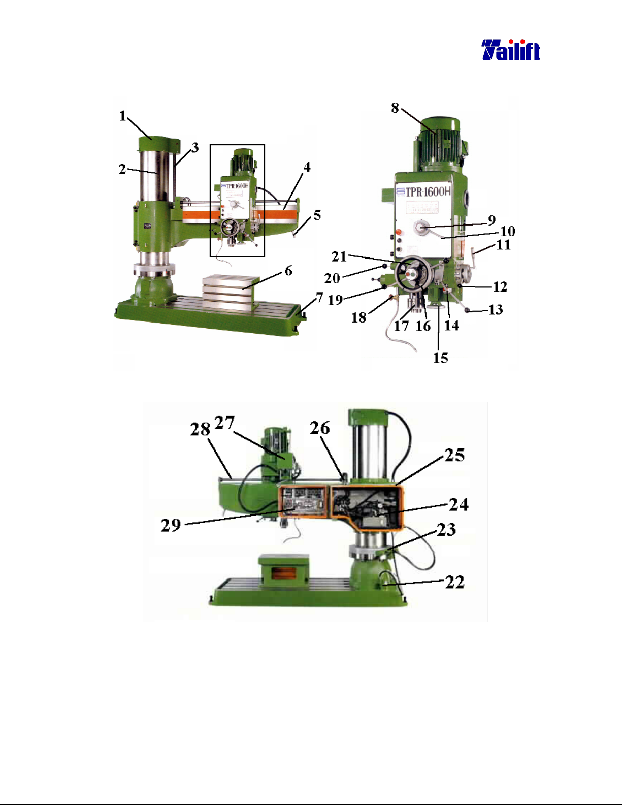
5.1.2 (For TPR-1600H/ For TPR-2000H)
The front view of the machine
The rear view of the machine
Page 33

5-4
The relevant names
:
No
Name Description
1 Top Cover It is located on the top of the Column, inside which Elevating Motor and Reducing
Speed Motor are installed.
2 Column It is designed to support the Gearbox and Arms. It connects with the Base.
3 Transmission ball
screw.
It is designed to transmit the rotation of the Elevating Motor to the Arm so that it
can move up and down.
4 Arm It is to support the Gearbox. It connects with the Column.
5 Rotating lever It is designed to move the Arm. It is easy and safe to use.
6 Work table It shortens the distance between the work piece and drilling bit. The T-shaped
surface facilitates the clamping and positioning of the work piece.
7 Base It serves as a foundation, the gravity center of the machine. It contains cutting fluids
inside. It can support the work piece. Its T-shaped surface facilitates the clamping
and positioning of the work piece.
8 Spindle Motor It is the source of the driving for the Spindle.
9 Three steps feeding
rate selection ring
It is designed to select the feeding rate. Used together with the two steps feeding rate
selection lever, it provides 6 options for the feeding rate.
10 Two steps feeding
rate selection ring
It is designed to select the feeding rate. Used together with the three steps feeding
rate selection lever, it provides 6 options for the feeding rate.
11 Dual Speed
changing lever
It is designed to switch the spindle rotation speed. Used together with the three steps
feeding rate selection lever, it provides 6 options for the feeding rate.
12 Triple speed
changing lever
It is designed to switch the spindle rotation speed. Used together with the two steps
feeding rate selection lever, it provides 6 options for the feeding rate.
13 High-low speed
changing lever
It is designed to switch the spindle rotation speed. Used together with the two and
three steps feeding rate selection lever, it provides 12 options for the feeding rate.
14 Auto feeding lever It is used simultaneously with the feeding lever to enable the auto mechanism.
15 Manual feeding
wheel
It indicates the scale of the manual feeding. It rotates simultaneously with the auto
feeding devices.
16 Hand wheel It is designed to move the Gearbox. It can move right- or leftward.
17 Spindle It is the place where the drilling bit, tapper and drill clamp head are installed to.
18 Cutting fluid
adjustment switch
While at drilling, cutting fluid might be used. The switch is used to control the
passage volume.
19 Feeding Lever It is to control on and off of the auto feeding mechanism.
20 Bit releasing lever When releasing the drilling bit, a releasing pin is used. This Bit releasing lever works
the same as the releasing pin.
21 Main Scale It indicates how deep the drilling has reached.
22 Cutting fluid pump It is designed to extract out the fluid from the container.
23 Column clamping
devise
24 Oil Pressure pump
motor
It is the dynamic source of the oil pressure pump.
25 Metal cover There are the ball screw and oil pressure pump inside. It is designed to protect the
operation and staffs’ safety.
26 Gearbox clamping
devise
It is designed to fasten the gearbox. It is used simultaneously with the ball screw.
27 Counter weight After feeding finished, the Spindle will return to the original point due to the counter
weight.
28 Guide lever It is designed to guide the gearbox movement and clamp it.
29 Electricity box Most of the control elements for the radial drill are put in this box.
Page 34
5-5
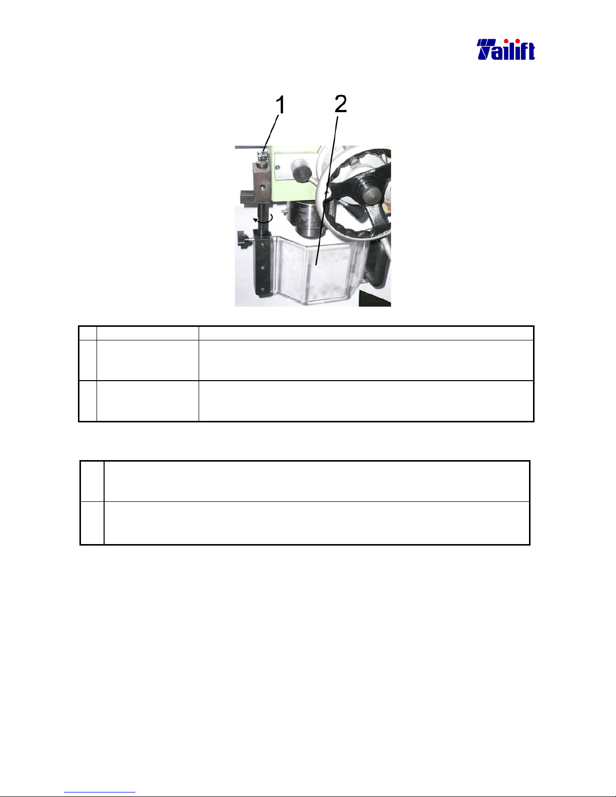
5.1.3 Safty protective device (suit every model)
No. Term Description
1 Safety Protective
Cover
For to avoid debris fly off. When spindle making the drilling bit,the cover
must be close. Another for safety, the spindle must stop rotation, when the
cover is open.
2 Limit Switch The limit switch is controlled by safety protective cover’s open or close.
If safety protective cover is open,the spindle stop rotation by limit switch’
single . Another,if safety protective cover is close,the spindle can rotation.
Precaution:
1. When user close the saftety protective cover(As marked 1) , the limit switch (As
marked 2)can message a signal to allow the spindle rotation.Therefore, user can
operation the machine.
2. When user open the saftety protective cover(As marked 1) , the limit switch (As
marked 2)can message a signal to stop the spindle rotation immediately.
Page 35
5-6
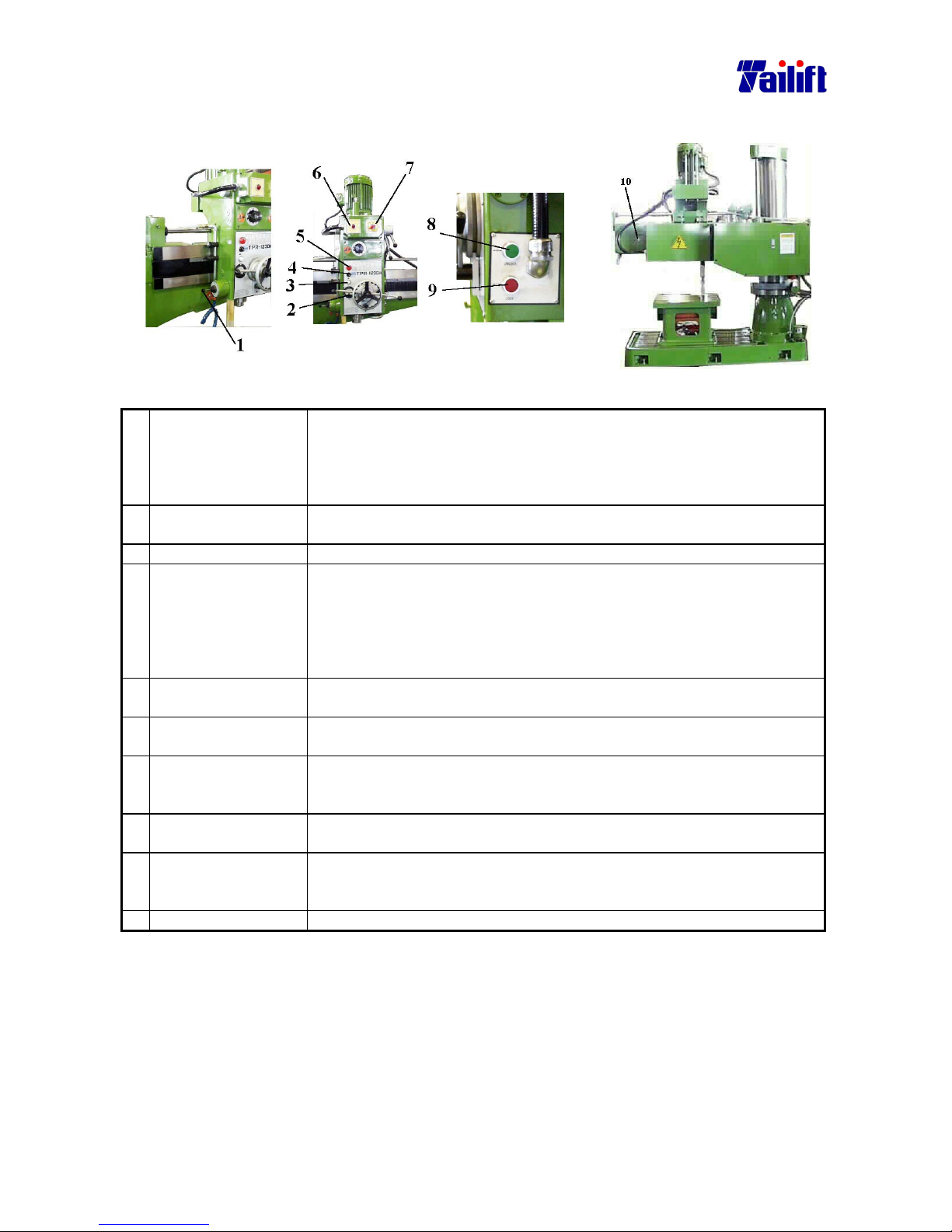
5.2 Instruction to switches
5.2.1 (For TPR-1230, TPR-1230H)(Type I)
The front view of the machine The rear view of the machine
Description for Switches.
1. Cross switch It is to control the elevating and revolution. There are four sign on it.
When switched to “SPDL. FOR.”, the spindle revolves clockwise. When
switched to “SPDL.REV.”, it revolves counter clockwise. When switched
to “ARM UP”, the Arm lifts. When switched to “ARM DOWN”, the arm
descends.
2. Electric current meter It is for operator’s understanding whether the working situation is
normal.
3. Feeding light It lights when at feeding. After work finished and power off, it turns off .
4. The cutting fluids
switch
It is a switch to start on or off the lubrication when at boring, where the
boring or shearing causes high temperature, making the drilling bit easy
to wear. The lubrication can reduce the temperature and lengthen the life
of the drilling bit. Turn on to start and off to stop the lubrication. The
floating capacity is decided by another knob called the cutting fluids
adjusting knob.
5. Emergent stop It is pressed to stop the machine when at processing and emergence
occurs. Pull it again for back to release the stop.
6. Power light When the external power and the main machine power switch are on, the
power light will be on, indicating to the operator that the power is on.
7. Pole change switch The spindle motor is a pole variable one. A regular motor has 4 pole. But
this one is changeable between 4 and 8 pole. It can change the spindle
rotating speed.
8. Release switch It is to release the clamping of the Arm and the Gearbox so that the
Gearbox can elevate, move for or backwards, left or rightwards.
9. Clamping switch It is used to clamp the Arm and the Gearbox. After the Gearbox, moveable
up and down, for and backwards, left and rightwards, is positioned, You
can use this switch to fasten the above mechanisms in positions.
10. Work light switch It is used to improve lighting where illumination is not enough.
Page 36
5-7
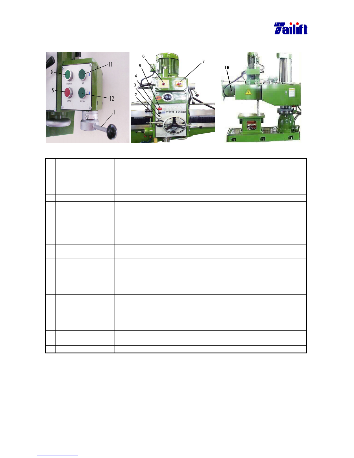
(For TPR-1230, TPR-1230H) (Type II)
The front view of the machine(Type II) The rear view of the machine
Description for Switches.
1. Cross switch Main Spindle forward-reverse Switch : When Switch to SPDL .For
The Spindle will forward . When switch to SPDL.REV,The spindle
will reverse.
2. Electric current meter It is for operator’s understanding whether the working situation is
normal.
3. Feeding light It lights when at feeding. After work finished and power off, it turns off .
4. The cutting fluids
switch
It is a switch to start on or off the lubrication when at boring, where the
boring or shearing causes high temperature, making the drilling bit easy
to wear. The lubrication can reduce the temperature and lengthen the life
of the drilling bit. Turn on to start and off to stop the lubrication. The
floating capacity is decided by another knob called the cutting fluids
adjusting knob.
5. Emergent stop It is pressed to stop the machine when at processing and emergence
occurs. Pull it again for back to release the stop.
6. Power light When the external power and the main machine power switch are on, the
power light will be on, indicating to the operator that the power is on.
7. Pole change switch The spindle motor is a pole variable one. A regular motor has 4 pole. But
this one is changeable between 4 and 8 pole. It can change the spindle
rotating speed.
8. Release switch It is to release the clamping of the Arm and the Gearbox so that the
Gearbox can elevate, move for or backwards, left or rightwards.
9. Clamping switch It is used to clamp the Arm and the Gearbox. After the Gearbox, moveable
up and down, for and backwards, left and rightwards, is positioned, You
can use this switch to fasten the above mechanisms in positions.
10. Work light switch It is used to improve lighting where illumination is not enough.
11. Arm uplift switch The arm will uplift when pushing the”UP” button.
12. Arm downlift switch The arm will be lowered down when pushing the”Down” button.
Page 37
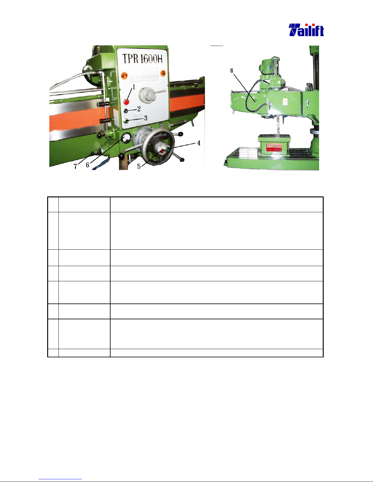
5-8
5.2.2 (For TPR-1600H/ TPR-2000H)
The front view of the machine The rear view of the machine
Description for Switches.
1. Emergent stop It is pressed to stop the machine when at processing and emergence occurs.
Pull it again for back to release the stop.
2. The cutting fluids
switch
It is a switch to start on or off the lubrication when at boring, where the
boring or shearing causes high temperature, making the drilling bit easy to
wear. The lubrication can reduce the temperature and lengthen the life of the
drilling bit. Turn on to start and off to stop the lubrication. The floating
capacity is decided by another knob called the cutting fluids adjusting knob.
3.
Power switch
(light attached)
When external power and the machine is on, the main power light will be on,
to indicate to the operator that the power is on.
4. Release switch It is to release the clamping of the Arm and the Gearbox so that the Gearbox
can elevate, move for or backwards, left or rightwards.
5. Clamping switch It is used to clamp the Arm and the Gearbox. After the Gearbox, moveable up
and down, for and backwards, left and rightwards, is positioned, You can use
this switch to fasten the above mechanisms in positions.
6. Electric current
meter
It is for operator’s understanding whether the working situation is normal.
7. Cross switch It is to control the elevating and revolution. There are four sign on it. When
switched to “SPDL. FOR.”, the spindle revolves clockwise. When switched to
“SPDL.REV.”, it revolves counter clockwise. When switched to “ARM UP”,
the Arm lifts. When switched to “ARM DOWN”, the arm descends.
8. Work light switch It is used to improve lighting where illumination is not enough.
Page 38
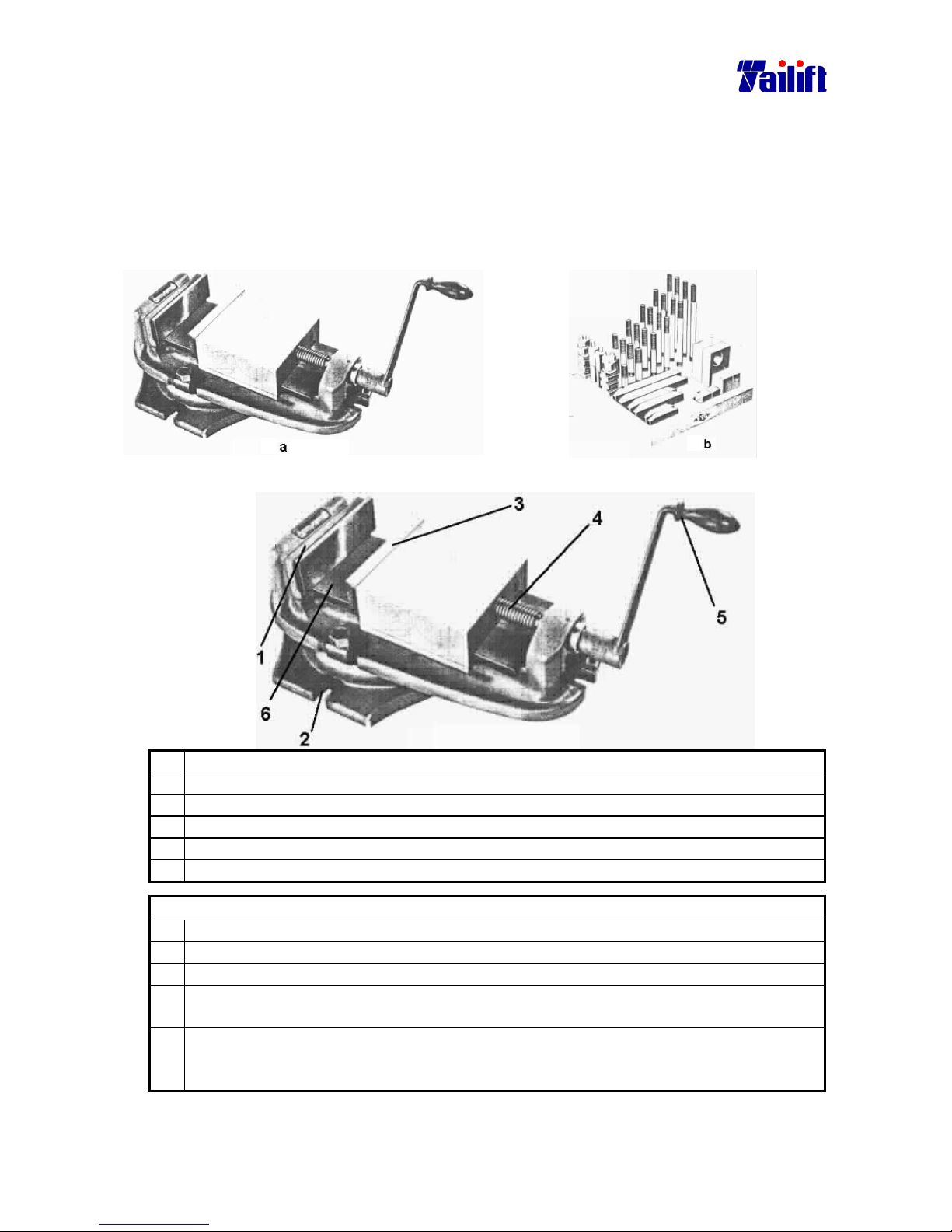
5-9
5.3 Installation of the clamp(work piece)
5.3.1 General
Work piece must be placed securely and precisely on the radial drill so that precision and
safe procession can be achieved. Regularly, a vise is applied. (as shown picture a). Since
the vise has its range limit, universal clamp (as shown picture b) is applied for bulky
work piece or any work piece which isn’t easy to be clamped. The universal clamp
includes T shape chamfer bolts, stacking plate, insertion blocks, which makes clamping
easier.
5.3.2 Introduction of the vise and the clamping of the work piece.
(1) The fixed side of the vise.
(2) The fixing side with T shape chamfer bolt and nuts
(3) The moving side of the vise.
(4) The screw bar.
(5) The handle.
(6) The surface of the vise.
Clamp work piece as the following:
a. Move away the drilling bit or lift the gearbox to the utmost point.
b. Using brush, clean the worktable and the vise surface.
c. Clean the vise surface using clean rag.
d. Position the work piece on the vise surface. If it is piercing drilling, please insert a
block under the work piece so that drilling into vise can be avoided.
e. Fasten the handle by rotating it clockwise and tighten it. While tightening it, please
use plastic hammer or copper bar to hit the work piece till there is no gap between
the work piece and the inserted block.
Page 39
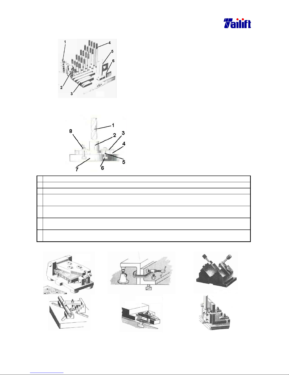
5-10
5.3.3 Universal clamp and the clamping of the work piece.
(1) Hex nuts
(2) T shape chamfer nuts
(3) Stacking plate
(4) Twin head bolts
(5) Insertion block
(6) Ladder block
Clamp the work piece as the following:(Since the combination of the universal clamp is very
flexible and abundant, The following diagram is applied as an exemplary description.
1. Drilling bit
2. Work piece
3. Stacking block
4. Insertion block
5. Twin head bolts
6. T shape chamfer bolts
7. Worktable
8. Hex but
a. Move away the drilling bit or lift the gearbox to the utmost point.
b. Using brush, clean the worktable and the vise surface.
c. Clean the vise surface using clean rag.
d. Position the work piece on the vise surface. If it is piercing drilling, please insert a block under the
work piece so that drilling into vise can be avoided.
e. After screwing the T shape chamfer nut to the twin head bolts with suitable length, put it into the T
shape chamfer of the worktable or the base.
f. Choose the insertion block or ladder block that is the same high as work flange. Put them in the
other side of the bolts.
g. Using holed stacking block, place them onto the bolts, with one of its side pressing the work flange
and another pressing the insertion block or ladder block, then tighten it with hex nuts.
Examples of clamping, using the universal clamp.
Page 40
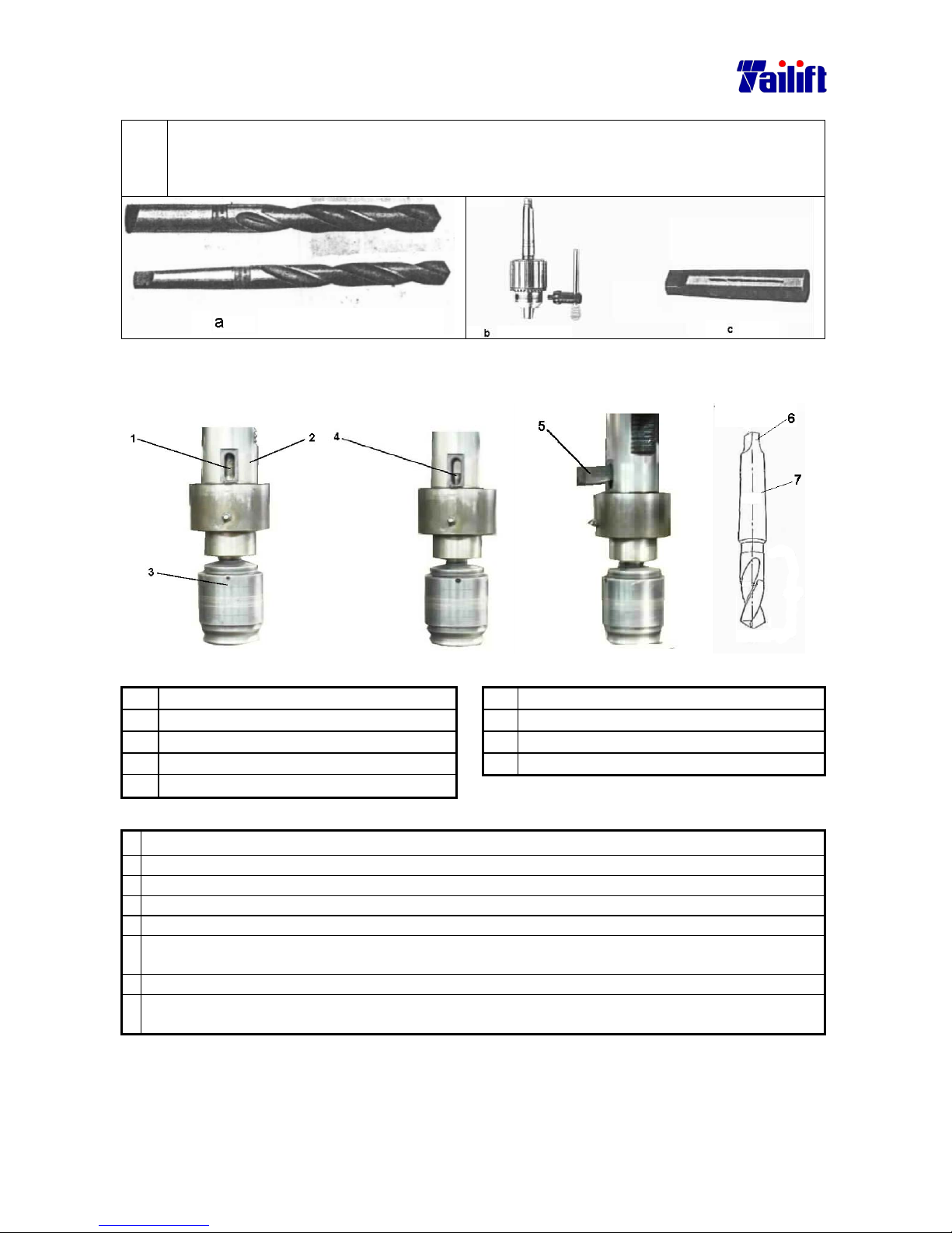
5-11
5.4 Installation and change of the drilling bit
The radial drill is mainly used in drilling. How to clamp the drilling bit is therefore very
important. Generally, drilling bits divides into two kinds, one is straight handle drilling bit,
and another is tapered handle one. (as fig. A). Their clamping is very different. The straight
handle one is fixed by a drilling head while the tapered handle one is fixed by a bushing.
5.4.1 The assembly and disassembly of the drilling head and clamp
Fig. a. Fig. b. Fig. c. Fig. d.
No. Term No. Term
(1) Revolving shaft. (5) Pin for releasing drill bit
(2) Shaft bushing (6) Drill shaft end
(3) Speedy drill bit clamp (7) Drilling shaft
(4) The stem for the speedy drill bit clamp
Disassemble the tapered handle drill bit and the drill head clamp as the following way:
a. Move away the drilling bit or lift the gearbox to the utmost point.
b. Power off machine.
c. Put on gloves.
d. Insert a thick wood plate into the underneath of the drill bit and the drill bit head.
e. Rotate the feed trip lever clockwise and have the spindle descend about 150 to 200 mm. As fig. a.
f. Rotate the revolving shaft from the bushing till that the drill shaft end and drill shaft are visible
from the hole of releasing drill bit. as fig. b.
g. Insert the pin for releasing the drill bit into the hole, as fig. c.
h. Hit the end of the pin for releasing drill bit, using plastic hammer or copper bar, till the drill bit
and the drill bit clamp fall onto the wood plate.
Precaution:
The distance between the thick wood plate, drill bit and the end of the drill bit clamp is about 30 mm.
Please dismantle the drill bit the following way when the bit releasing devise of the TPR-1600H cannot work.
Page 41
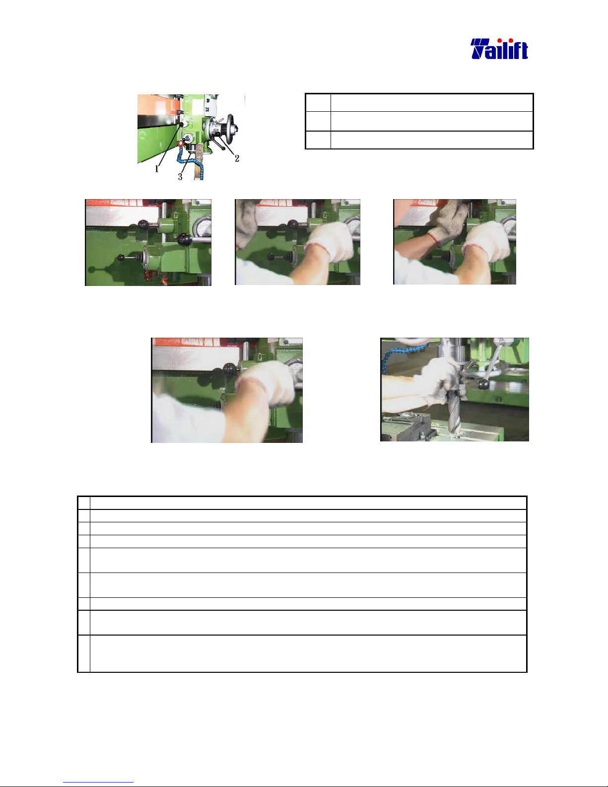
5-12
The way to use the releasing taper handle head and clamping head follows as:
(only applicable for TPR-1600H /TPR-2000H)
1 The lever for releasing the drilling bit.
2 The feeding lever
3 The spindle
To dismantle as follows:
Step 1. Stand at the left side
of the machine.
Step 2 Grasp the feeding lever
using right hand and
release the spindle to its
utmost position.
Step 3. Press down the bit
releasing lever using left
hand.
Step 4. Keep grasping the drilling bit using left hand and rotate the feeding
lever counter clockwise until the bit comes out.
Assemble the drill bit head and the drill bit clamp as the following:
a. Move away the drilling bit or lift the gearbox to the utmost point.
b. Power off.
c. Put on gloves.
d. Insert a thick wood plate into the underneath of the drill bit and the drill bit clamp.
e. Rotate the feed trip lever clockwise and have the spindle descend about
150 to 200 mm. As fig. a.
f. Rotate the revolving shaft from the bushing till that thing behind the machine is visible from the
hole of releasing drill bit, as fig. b.
g. Place the drill bit clamp end up, as fig. d.
h. Place the drill bit and its clamp end into the revolving shaft and have the drill shaft end inserted
into the hole for releasing the drill bit, as fig. b.
i. Rotate the feed trip lever counter clockwise. Make the spindle descend till the drill bit and the
bottom end of the drill bit clamp head contact the wood plate. Apply a little bit force and complete
it by confirming that the drill bit won’t fall.
Precaution:
The distance between the thick wood plate, drill bit and the end of the drill bit clamp is about 30
mm.
Page 42
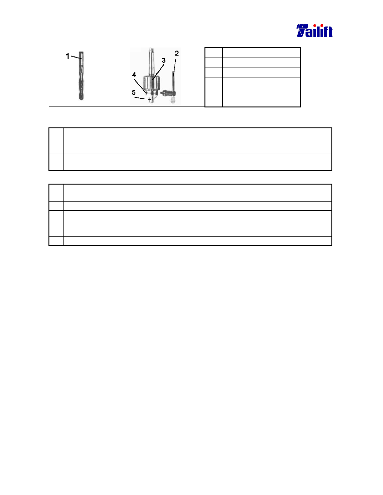
5-13
5.4.2 The assembly and disassembly of the straight handle drill bit
No. Term
(1) Drill bit
(2) Drill spanner
(3) Tightening ring
(4) Hole for drill spanner.
(5) Drill bit clamp head.
Fig. a. Fig. b.
Disassemble the straight drill bit as the following way:
a. Move away the drilling bit or lift the gearbox to the utmost point.
b. Power off.
c. Put on gloves.
d. Put the drill spanner into the hole for tightening.
e. Rotate the spanner counter clockwise till the clamp head falls.
Assemble the straight handle drill bit as the following way:
a. Move away the drilling bit or lift the gearbox to the utmost point.
b. Power off.
c. Put on gloves.
d. Adjust the tightening ring till the drill bit can be inserted.
e. Insert the drill bit into the clamp head at least 25 mm.
f. Put the drill spanner into the hole for tightening.
g. Rotate the spanner clockwise till the drill bit is tightened.
Precaution:
The drill bit must be inserted at least over 25 mm, otherwise the bit get easily broken or
can’t drill very precisely.
5.5 Power on and off.
5.5.1 Power on
a. Turn outside main switch to ”ON” position.
b. Turn the machine power switch to ”ON” position.
5.5.2 Power off
a. Turn the machine power switch to ”OFF” position.
b. Turn outside main switch to ”OFF” position.
Precaution:
When at emergency, please press down the emergent stop button to shut down the
power supply.
But the emergent stop button can’t be used as a switch for normally stopping
machine or normal power off.
Page 43
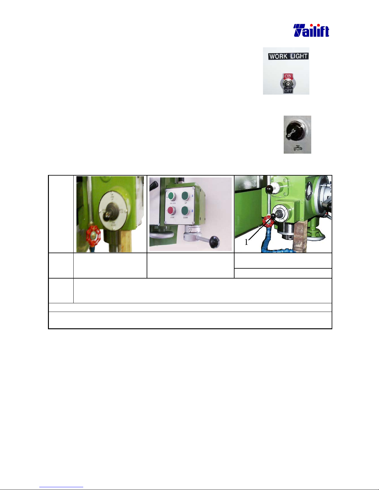
5-14
5.6 Work light
Turn on the work light. Switch the work light to ”ON”
position.
Turn off the work light. Switch the work light to ”OFF”
position.
5.7 Cutting fluids
Turn on the cutting fluids. Switch the cutting fluids to ”ON” position.
Turn off the cutting
fluids.
Switch the cutting fluids to ”OFF” position.
5.8 Elevating the arm .
Diagra
ms
1
Cross Switch.
Descrip
tion
For
TPR-1230,TPR-1230H
(Type I)
For TPR-1230,TPR-1230H
(Type II)
For TPR-1600H, TPR-2000H
Steps Turn the cross switch to “ARM UP” if you want to elevate it up, Turn the cross switch
to “ARM DOWN” if you want to elevate it down. Turn the cross switch to the middle
after the Arm reaches the required position.
Precaution
When the Arm is elevating, the clamping device will release itself automatically. When the
cross switch is turned to the middle, the clamping device will tighten itself automatically.
Page 44
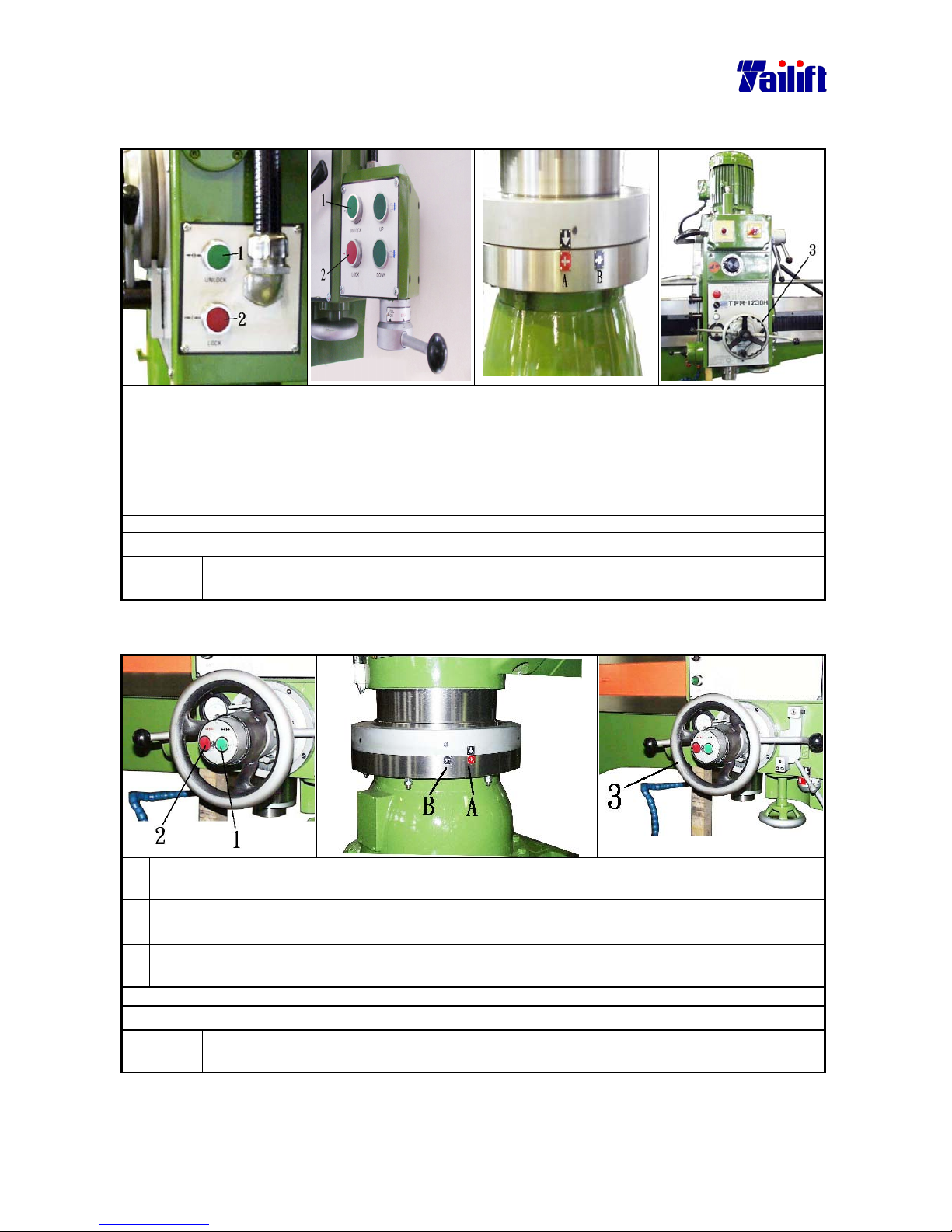
5-15
5.9 Rotate the Gearbox right or leftwards.
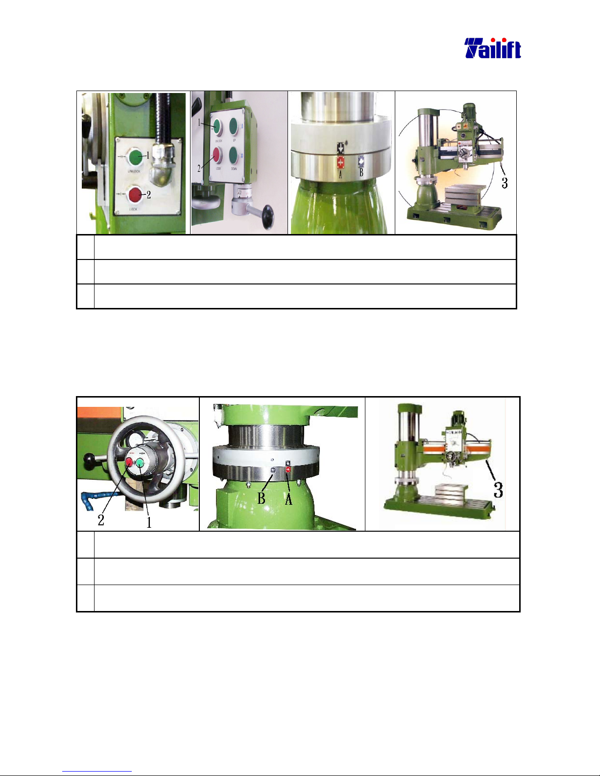
5.9.1(For TPR-1230,TPR-1230H)
1. Press the figure1 shown in the bottom left. Referring to the up right picture, release the
button after pointing the arrow head to B. The clamping device is released now.
2.
Rotate the hand wheel clockwise to move rightwards and counter clockwise to move
leftwards, as shown in up left picture.
3. Press the figure 2 shown in the bottom left. Referring to the up right picture, release the
button after pointing the arrow head to A. The clamping device is tightened now.
Precaution:
After UNLOCK pressed, the Arm can move for and backwards in addition to
move left and right wards.
5.9.2(For TPR-1600H/ TPR-2000H)
1. Press the figure1 shown in the bottom left. Referring to the up right picture, release the
button after pointing the arrow head to B. The clamping device is released now.
2.
Rotate the hand wheel clockwise to move rightwards and counter clockwise to move
leftwards, as shown in up left picture.
3. Press the figure 2 shown in the bottom left. Referring to the up right picture, release the
button after pointing the arrow head to A. The clamping device is tightened now.
Precaution:
After UNLOCK pressed, the Arm can move for and backwards in addition to
move left and right wards.
Page 45
5-16
5.10 Rotate the arm forward or backwards.
5.10.1 (For TPR-1230,TPR-1230H)
1. Press the figure1 shown in the bottom left. Referring to the up right picture, release the
button after pointing the arrow head to B. The clamping device is released now.
2.
Push the arm moving lever backwards to move the arm backwards, as shown in figure 3. Pull the
arm moving lever towards to move the arm towards, as shown in figure 3.
3.
Press the figure2 shown in the bottom left. Referring to the up right picture, release the button
after pointing the arrowhead to A. The clamping device is tightened now.
Precaution:
After UNLOCK pressed, the Arm can move for and backwards in addition to move left and
right wards. If 180 degree rotation is needed, the ground needs to be processed according the
method in the chapter 3, where the base bolts are required and need to be fastened by nuts.
5.10.2(FOR TPR-1600H, TPR-2000H)
1. Press the figure1 shown in the bottom left. Referring to the up right picture, release the
button after pointing the arrow head to B. The clamping device is released now.
2.
Push the arm moving lever backwards to move the arm backwards, as shown in figure 3.
Pull the arm moving lever towards to move the arm towards, as shown in figure 3.
3.
Press the figure2 shown in the bottom left. Referring to the up right picture, release the
button after pointing the arrowhead to A. The clamping device is tightened now.
Precaution:
After UNLOCK pressed, the Arm can move for and backwards in addition to move
left and right wards. If 180 degree rotation is needed, the ground needs to be
processed according the method in the chapter 3, where the base bolts are required
and need to be fastened by nuts.
Page 46
5-17
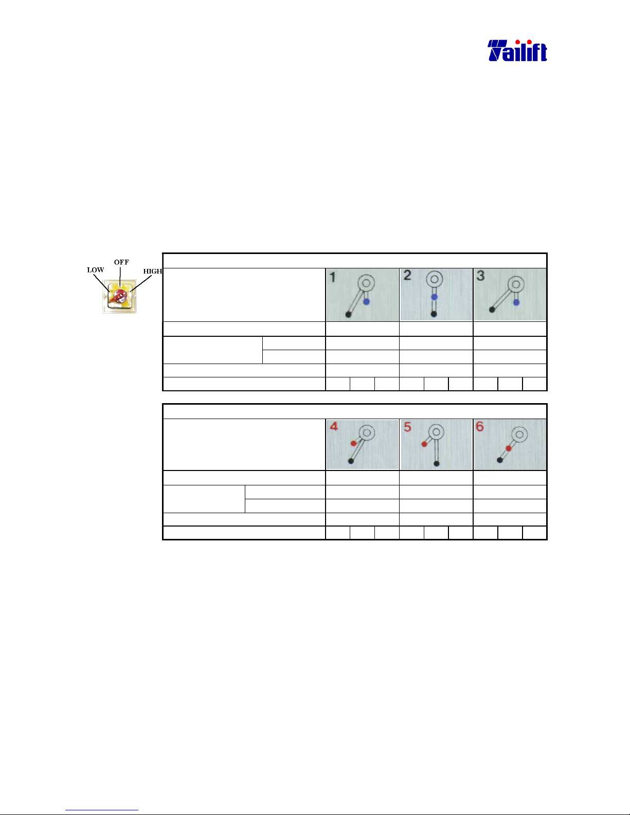
5.11 Change the spindle speed.
Warning:
Spindle temperature will go up making operation in trouble when the
spindle speed is set at high rotation mode without movement of the
quill. So please do not set the spindle speed at high rotation mode
when no movement of the quill.
5.11.1(For TPR-1230,TPR-1230H)
Ⅰ. The speedometer at the time when the pole switch is in high position.
(For TPR-1230,TPR-1230H)
The position for the pole switch.(For TPR-1230,TPR-1230H)
Two speed change lever(low speed)
Speed change levels
Speed(rpm) 88 154 282
Mild steel
∅25-∅40 ∅19-∅25 ∅12-∅19
Suitable drilling
diameter (mm)
Cast iron
∅38-∅55 ∅28-∅38 ∅22-∅28
Threading (metric) M16-M20 M6-M16 M3-M6
Suitable automatic feeding step. 1 2 3 1 2 3 1 2 3
Two speed change lever(high speed)
Speed change levels
Speed(rpm)
456 796 1500
Mild steel
∅10-∅12 ∅6-∅10 ∅3-∅6
Suitable drilling
diameter mm
Cast iron
∅19-∅22 ∅10-∅19 ∅3-∅10
threading(metric) Not suggested. Not suggested. Not suggested.
Suitable automatic feeding step. 1 2 3 1 2 3 1 2 3
Page 47
5-18
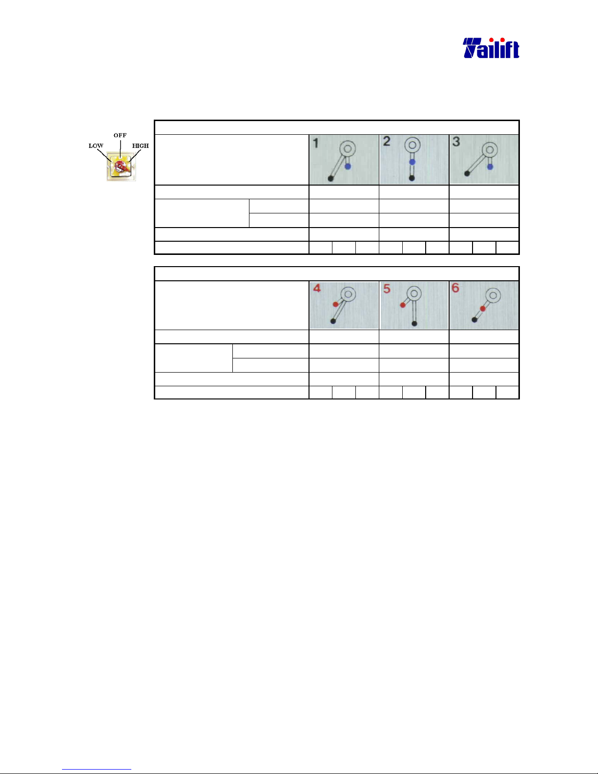
Ⅱ. The speedometer at the time when the pole switch is in low position.
(For TPR-1230,TPR-1230H)
The position for the pole switch.(For TPR-1230,TPR-1230H)
Two speed change lever(low speed)
Speed change levels
Speed(rpm)
44 77 141
∅25-∅40 ∅25-∅40 ∅19-∅25
∅12-∅19
Suitable drilling
diameter (mm)
∅38-∅55 ∅38-∅55 ∅28-∅38
∅22-∅28
Threading (metric)
M16-M20 M16-M20 M6-M16
Suitable automatic feeding step. 1 2 3 1 2 3 1 2 3
Two speed change lever(high speed)
Speed change levels
Speed(rpm)
228 398 750
∅12-∅19 ∅10-∅12 ∅6-∅10
∅3-∅6
Suitable drilling
diameter mm
∅22-∅28 ∅19-∅22 ∅10-∅19
∅3-∅10
threading(metric)
M3-M6
Not suggested. Not suggested.
Suitable automatic feeding step. 1 2 3 1 2 3 1 2 3
Page 48
5-19
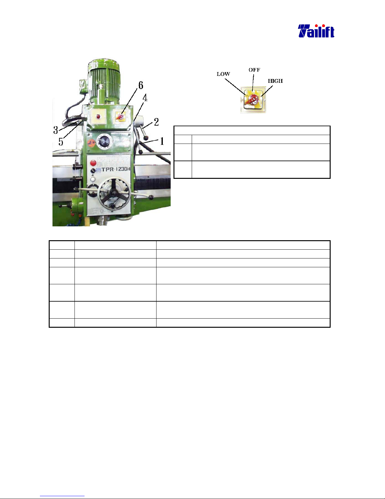
Ⅲ.Change spindle speed.
Label 6 of detail.
Low If the pole switch to high position, its 8 pole.
OFF If the pole switch to “OFF” position, the
motor can’t turn run.
High If the pole switch in high position, its 4 pole.
Normal, switch to high position.
Pic. a.
No. Term Description
1. Three speeds change lever
2. Two speeds change lever High and low speeds change lever.
3. Indicating ring for high
and low speed.
It is to indicate the current speed.
4. Reference point for the
three speeds change lever
It refers to the current position of the three speeds
change lever.
5. Reference point for the
two speeds change lever
6. Pole change switch
Ⅳ. Change the spindle speed as the following way:
a. Have spindle rotate.
b. Look up in the speed table and choose a suitable speed rate.
c. Turn on the switch for the feed rate.
Precaution when changing speed:
a. Spindle rotation must be stopped when at changing speed.
b. Please press down the emergent stop button for safety reason.
c. Change speed only after the spindle stops completely.
Page 49
5-20
5.11.2(For TPR-1600H/ TPR-2000H)
Ⅰ.Speedometer(For TPR-1600H/ TPR-2000H)
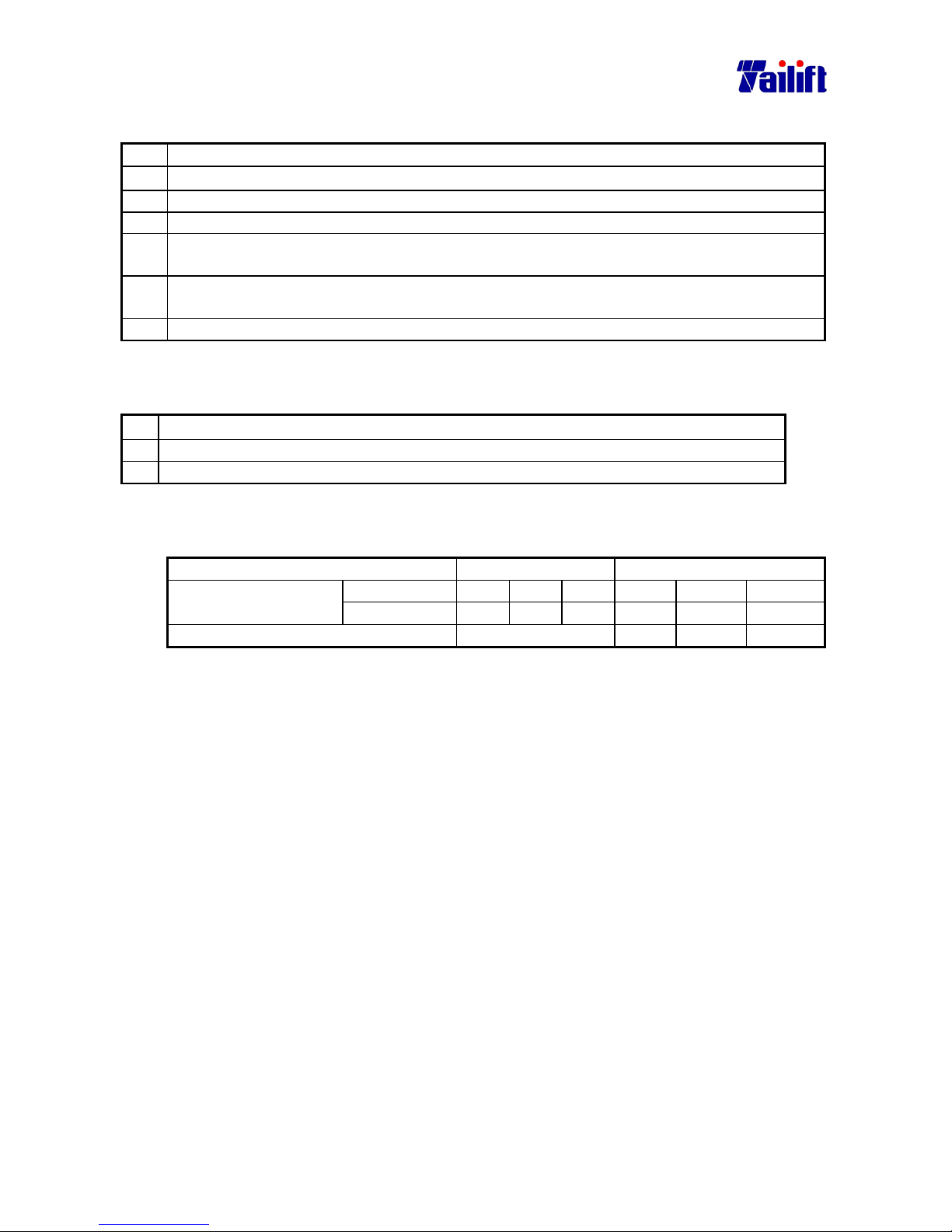
Two step choice 1 2
H (hi-speed)
1890 1010 475 220 115 55
Speed(rpm)
L (lo-speed) 1330 715 335 155 80 35
Mild steel
∅1-∅6 ∅6-∅24 ∅14-∅24 ∅24-∅36 ∅36-∅50 ∅50-∅66
Applicable
diameter mm
Cast iron
∅1-∅8 ∅8-∅18 ∅18-∅30 ∅30-∅44 ∅44-∅60 ∅60-∅78
Ⅱ. speed switch(For TPR-1600H/ For TPR-2000H)
Fig.1.
Fig.2. Fig.3.
The relevant names
The relevant names The relevant names
a. Step 1
d. Ref. Point for the
step 1.
h. Hi-lo speed
indicator
b. Step 2
e. Ref. Point for the
step 2.
i. Hi-lo speed
changing lever
c. Two speed lever
f. Three step speed
changing lever
j. Hi-lo speed
reference point
g. Speedometer
(FOR TPR-1600H/ TPR-2000H)
The way to switch speed follows as:
Step Description
a. Stop rotation of the spindle.
b. Press down the emergency button.
c. Check the speedometer and select the suitable speed.
d. Switch the two step speed changing lever (as mark c in the fig. 1.) to the required
position. (Select the required step)
e. Switch the three step speed changing lever to the required position. When the two step
speed changing lever is at the step 1, the speed will be based on the reference point of
the step 1 (as mark d in the fig. 2). On the contrary, when the two step speed changing
lever is at the step 2, the speed will be based on the reference point of the step 2 (as
mark e in the fig. 2).
f. Switch the Hi-lo speed changing lever to the required position.
Page 50
5-21
Example:The following is the way to select the spindle speed at 115rpm:
Step Description
a. Stop the rotation of the spindle.
b. Press down the emergency button.
c. Check the speedometer and select the speed of 115 rpm.
d. Switch the two step speed changing lever to step 2. That’s to align the speed changing
lever (as mark c in the fig. 1) to the step 2. (as the mark b in the fig. 1)
e. Switch the three step speed changing lever to 115 and 80 (as the mark g in the fig. 2)
and align it to the reference point of the step 2 (as the mark e in the fig. 2)
f. Align the H of the Hi-lo speed changing lever to the Hi-lo speed indicator.
Ⅲ. Precaution to switch the rotation speed:
(Application model TPR-1600H/ TPR-2000H)
a. Rotating Spindle must be stopped when at changing rotation speed.
b. Please press down the emergency stop for safety.
c. Start to switch the rotation speed only when the spindle stops running.
Ⅳ. Precaution to switch the rotation speed:
(Application model TPR-1600H/ TPR-2000H)
1 2
H(Hi speed)
1890 1010 475 220 115 55
Rotation speed
(rpm)
L(Lo speed)
1330 715 335 155 80 35
Threading (metric)
Not suggested. M3-M6 M6-M16 M16-M20
Page 51

5-22
5.12 Automatic Feed.
5.12.1 (For TPR-1230, TPR-1230H)
Ⅰ. Automatic feed rate table
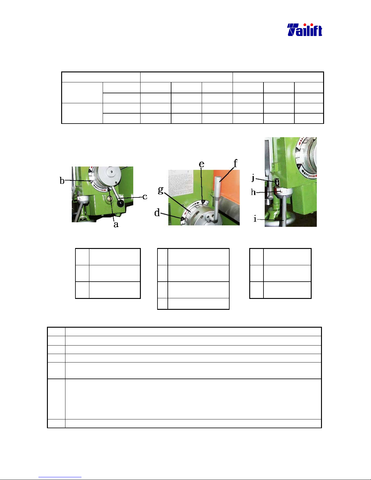
Steps N 1 2 3
Feed rate No feed rate 0.05mm/Rev 0.09 mm/Rev 0.15 mm/Rev
Ⅱ. Change the feed rate as the following way:
a. Stop the spindle.
b. Press down the emergent stop button.
c. Check the speedometer and choose a suitable rate.
d. Switch the feed rate.
Precaution when at changing feed rate:
You can change the feed rate only when the spindle is rotating.
Ⅲ. Suppose that the work piece is by the machine
The way to move(less than 25kgs.)
Suppose that the work piece is by the machine, the way to move it is as follows:
1. Power off.
2. Put on gloves.
3. Squat facing the work piece.
4. Lift the work piece with two hands.
5. When you are standing up, lift and move the work piece with your feet strength.
6. Move the work piece toward the worktable.
The way to move(greater than 25kgs.)
Suppose that the work piece is by the machine, the way to move it is as follows:
1. Power off.
2. Put on gloves.
3. Push the arm backwards.
4. Move a lifting devise close to the work piece.
5. Place lifting ropes or slings under the work piece, (please use two ropes or
slings). If the work piece has holes for lifting ropes or slings, please lock it with
ring head pin, then lift and move it with a hook.
6. Move the work piece toward the worktable.
Page 52
5-23
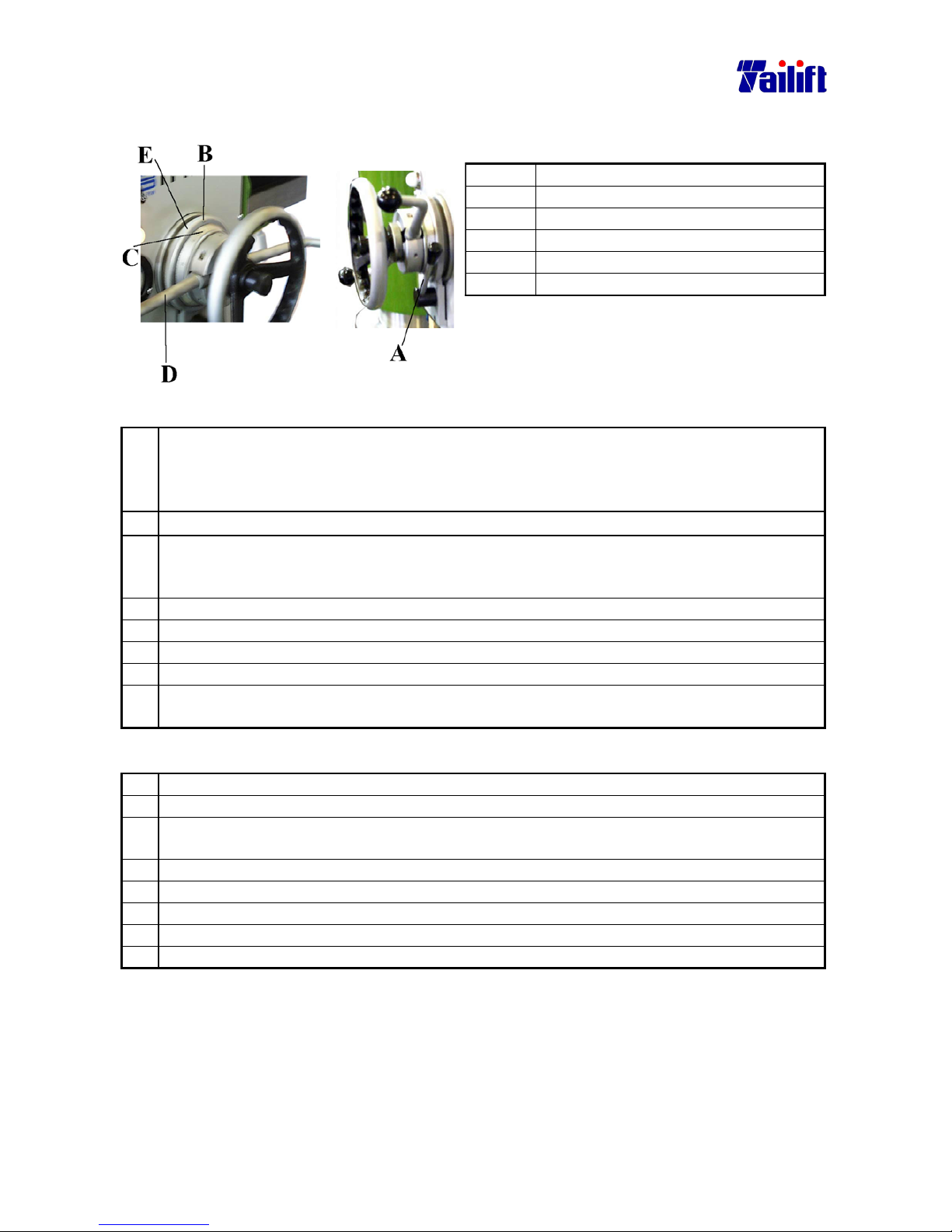
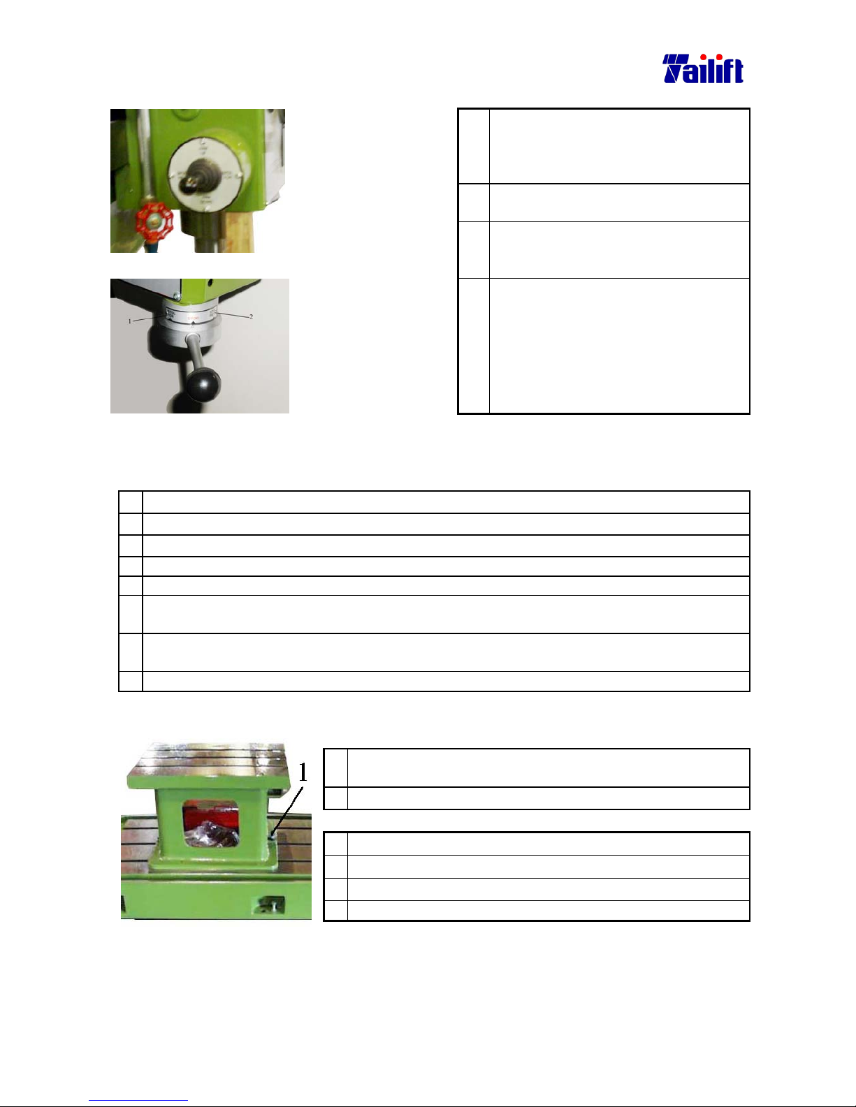
Ⅳ. How to preset the depth of the power-feed?
The relevant terms
Position Term
A Depth controlling and fixing lever.
B Depth reference point.
C Main dial
D Feed trip lever
E Depth-setting ring
Preset the depth of the power-feed:
a. Rotate the feed trip lever counter clockwise as shown in label D till The drill bit contact
the work piece. (At this moment, label B shown in the pictures move simultaneously.
That’s the depth is zero when the bit is contacting the work piece and the dial is also at
the zero position. )
b. Release the fixing lever of the main dial. That’s to release label A shown in the picture.
c. Rotate the depth setting ring as shown in label E, referring to the depth point on the
ring label B. To set the drilling depth is to adjust and align the gauge on the ring as
shown in the label C.
d. Clamp the fixing lever of the main dial. That’s to clamp label A shown in the picture.
e. Release the feed trip lever as shown in the label D.
f. Rotate the feed trip lever a little bit counter clockwise, as shown in the label D.
g. Turn the spindle switch to “SPDL. FOR”.
h. Pull the feed trip lever backwards as shown in the label D, The spindle will feed at the
chosen rate and stop
Example:How to preset a depth of 30mm?
a. Rotate D as in the picture till it contacts the work piece.
b. Release A, as shown in the picture.
c. Rotate E and align C as shown in the picture to the position of 30 mm on the B, as shown
in the picture.
d. Clamp A, as shown in the picture.
e. Release D, as shown in the picture.
f. Rotate D in the picture a little bit counter clockwise.
g. Turn the spindle switch to SPDL. FOR
h. Pull the feed trip lever as shown in the picture D backwards.
Precaution
a. Auto feed will move only after the feed rate is set up.
b. Auto feed is used only in drilling, not in threading.
Page 53
5-24
5.12.2 (For TPR-1600H/ TPR-2000H)
Ⅰ.The auto feeding rate table(Application model: TPR-1600H/ TPR-2000H)
Two step feeding rate selection
Step 1 Step 2
Feeding rate mm/Rev 0.96 0.56 0.31 0.21 0.12 0.07
Ⅱ. The way to switch the feeding rate follows as: (Application model: TPR-1600H/ TPR-2000H)
a. Stop the running spindle.
b. Check the speedometer and select a suitable speed.
c. Turn on the feeding rate switch.
The precaution to switch the feeding rate follows as:
a. When you switch the feeding rate, the spindle has to be at running.
Ⅲ. The way to set up the depth of the auto feeding follows as:
(Application model:TPR-1600H /TPR-2000H)
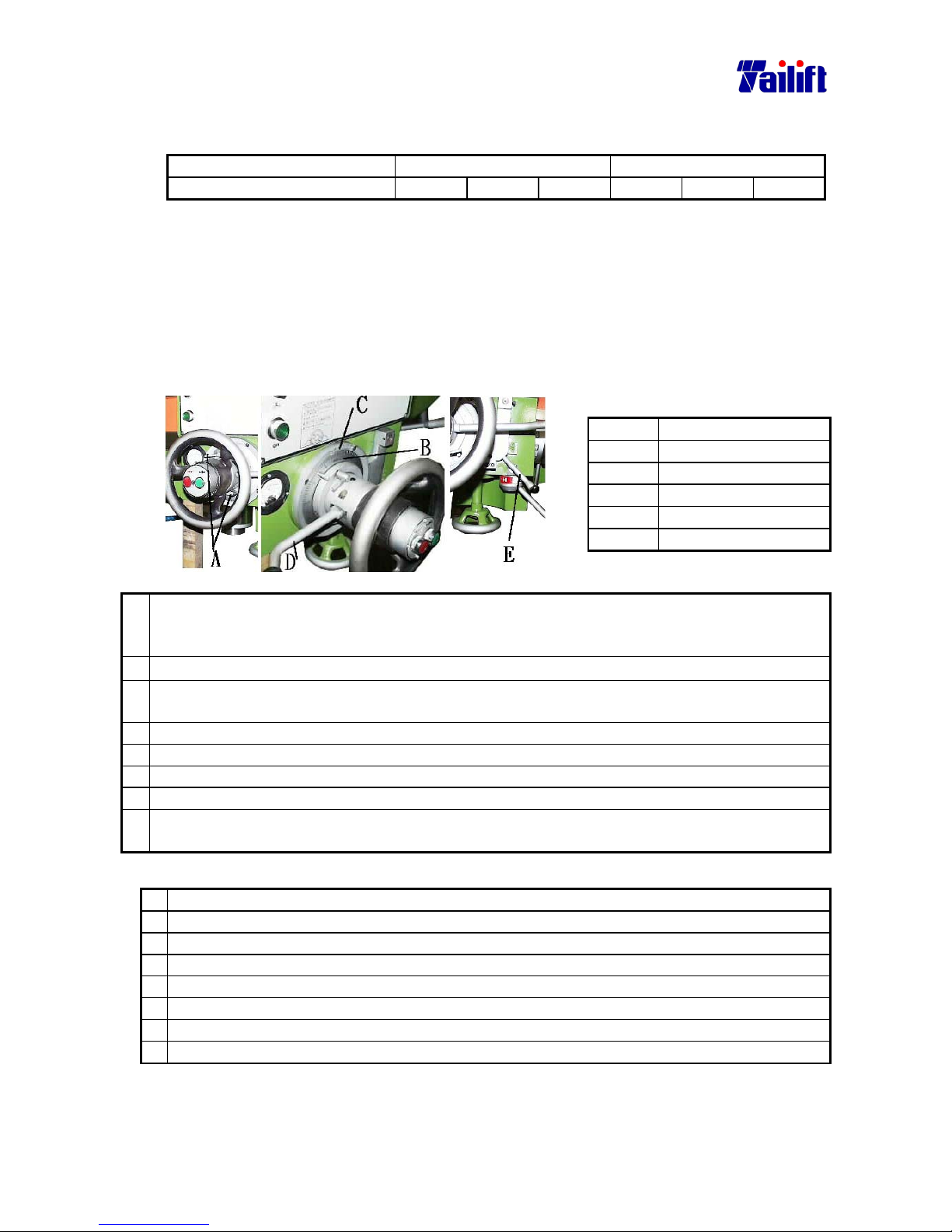
The relevant names
position name
A Depth control lever
B Main scale
C Depth reference point
D Feeding lever
E Auto feeding lever
The way to set up the depth of auto feeding follows as:(Application model: TPR-1600H/ TPR-2000H)
a. Rotate the feeding lever (as mark D) counter clockwise until the drilling bit contacts the work
piece (at this time, Mark B will be turning also. The depth is zero when the drilling touches the
work piece and the main scale is also pointing to 0 position.)
b. Release those two main scale levers. That’s to release the mark A in the fig.
c. Rotate the main scale (mark B). Using the depth reference point on the depth setup ring (mark C),
set up the drilling depth, which is also the main scale ring’s reading.
d. Clamp the main scale ring. That’s to clamp the mark A in the fig.
e. Release the feeding lever (mark D)
f. Rotate the feeding lever (mark D) a little bit counter clockwise.
g.
Turn the spindle switch to SPDL. FOR.。
h. Pull the feeding lever (mark D) backwards and push the auto feeding lever downwards. Then the
spindle will be feeding at the selected rate and stop at the set depth.
Example:To set up a depth of 30 mm.
a. Rotate the mark D until the drilling bit touches the work piece.
b. Release the mark A.
c. Rotate the mark B. Align the mark C to the mark B, at its scale 30.
d. Clamp the mark A.
e. Release the mark D.
f. Rotate the mark D a little bit counter clockwise.
g. Turn the spindle switch to SPDL. FOR
h. Pull the feeding lever (mark D) backwards and push downward the auto feeding lever.
Precaution
a. The feeding rate must be set up before the auto feeding can move.
b. The auto feeding is suitable to be used in threading, but not in boring.
Page 54
5-25
5.13 The spindle
1. Please turn on the main switch of
The Machine , and then lower down
the Quill 5mm, so that the forward
/reverse of the main spindle can start.
2. The main spindle will forward when
Switching to SPDL.FOR.
For
TPR1230,TPR1230H
(Type I)
3. If you want to stop the rotating of the
Spindle, Please switch to the middle
Position.
For
TPR1230,TPR1230H
(Type II)
4. The main spindle will reverse when
Switching to SPDL.FOR.
5.14 Threading
The way to thread is as follows:
a. Clamp the screw tap with drilling head.
b. Move the spindle to the top of the threading.
c. Set the feed rate at ”N”。
d. Rotate the feed trip lever a little bit counter clockwise.
e. After the cross switch turned to “SPDL.FOR”, the spindle spins clockwise.
f. Rotate the feed trip lever counter clockwise till the threading is finished. (The operator
decides the threading depth.)
g. After the cross switch turned to “SPDL.REV.”, let the spindle turn counter clockwise till
the screw tap retreats completely.
h. Turn the cross switch to the middle to stop the spindle.
5.15 The assembly and disassembly of the work table
.
Disassemble it as follows:
1. Release 1, as shown in the picture, using a spanner. That’s
to move the spanner counter clockwise.
2. Apply the above to the other side.
Assembly it as follows:
1.
Clean the debris from the base with a metal brush.
2.
Clean the worktable and the base with rags.
3.
Place T shape Bolts into the T shape chamfer of the base.
4. Tighten the nuts.
Page 55

5-26
5.16 Cutting fluids for all kinds of material
Soft steel crude oil、animal fat
Mild steel crude oil、animal fat
High carbon steel crude oil、animal fat
Stainless steel crude oil、animal fat
Manganese steel crude oil、animal fat
Cast iron Without
Malleable cast iron Crude oil
Brass, bronze Kerosene
Aluminum and alloy Kerosene
When cutting fluids is not applied, Having the turning speed and the feed rate reduced is
the only way to extend the tool life.
If cutting fluids leaks or injects to the aisle, please clean it immediately from the floor.
Page 56
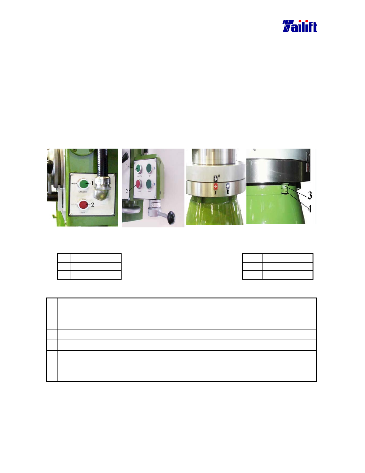
6-1
CHAPTER 6
Adjustment
6.1General
Adjustment is needed after the machine has been used a period of time for its parts will
get loose or worn out, In the radial drill, there are three parts needed to be adjusted. One is
the arm clamping lever, another the gap between the gearbox and the arm rail, finally the
engagement between the feed trip lever and the clutch.
6.2 The arm clamping lever
After the machine has been used for about 3-5 years, the position of the arm clamping
lever will be descending. It is the time to adjust the position of the adjusting nut.
6.2.1(For TPR-1230, TPR-1230H)
Fig. a. Fig. a-1 Fig. b. Fig. c.
The relevant names
The relevant names
No. name No. name
1. Release switch 3. Adjusting nut
2. Clamping switch 4. Fastening nut
Adjust the arm clamping lever as follows:
a. Press the figure1 shown in the bottom. Referring to the up right picture, release the
button after pointing the arrow head to b. The clamping device is released now.
b. Release the fastening nuts, totally 5 pieces, in the figure c and mark 4.
c. Using a wrench, adjust the nuts counter clockwise about 180°. (totally 5 pieces bolts)
d. Fasten the nuts, marked 4 in the figure c. (totally 5 pieces bolts)
e. Press the figure2 shown in the bottom left picture 1. Referring to the up right picture,
release the button after pointing the arrowhead to A. The clamping device is tightened
now.
Page 57
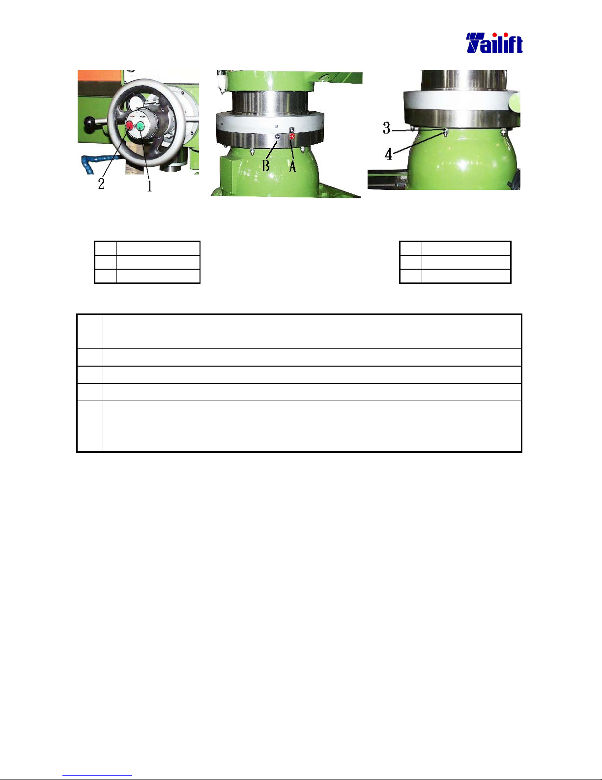
6-2
6.2.2(For TPR-1600H/ TPR-2000H)
Fig. a. Fig. b. Fig. c.
The relevant names
The relevant names
No. name
No. name
1. Release switch
3.
Adjusting nut
2. Clamping switch
4.
Fastening nut
Adjust the arm clamping lever as follows:
a. Press the figure1 shown in the bottom. Referring to the up right picture, release the
button after pointing the arrow head to b. The clamping device is released now.
b. Release the fastening nuts, totally 5 pieces, in the figure c and mark 4.
c. Using a wrench, adjust the nuts counter clockwise about 180°. (totally 5 pieces bolts)
d. Fasten the nuts, marked 4 in the figure c. (totally 5 pieces bolts)
e. Press the figure2 shown in the bottom left picture 1. Referring to the up right picture,
release the button after pointing the arrowhead to A. The clamping device is tightened
now.
Page 58
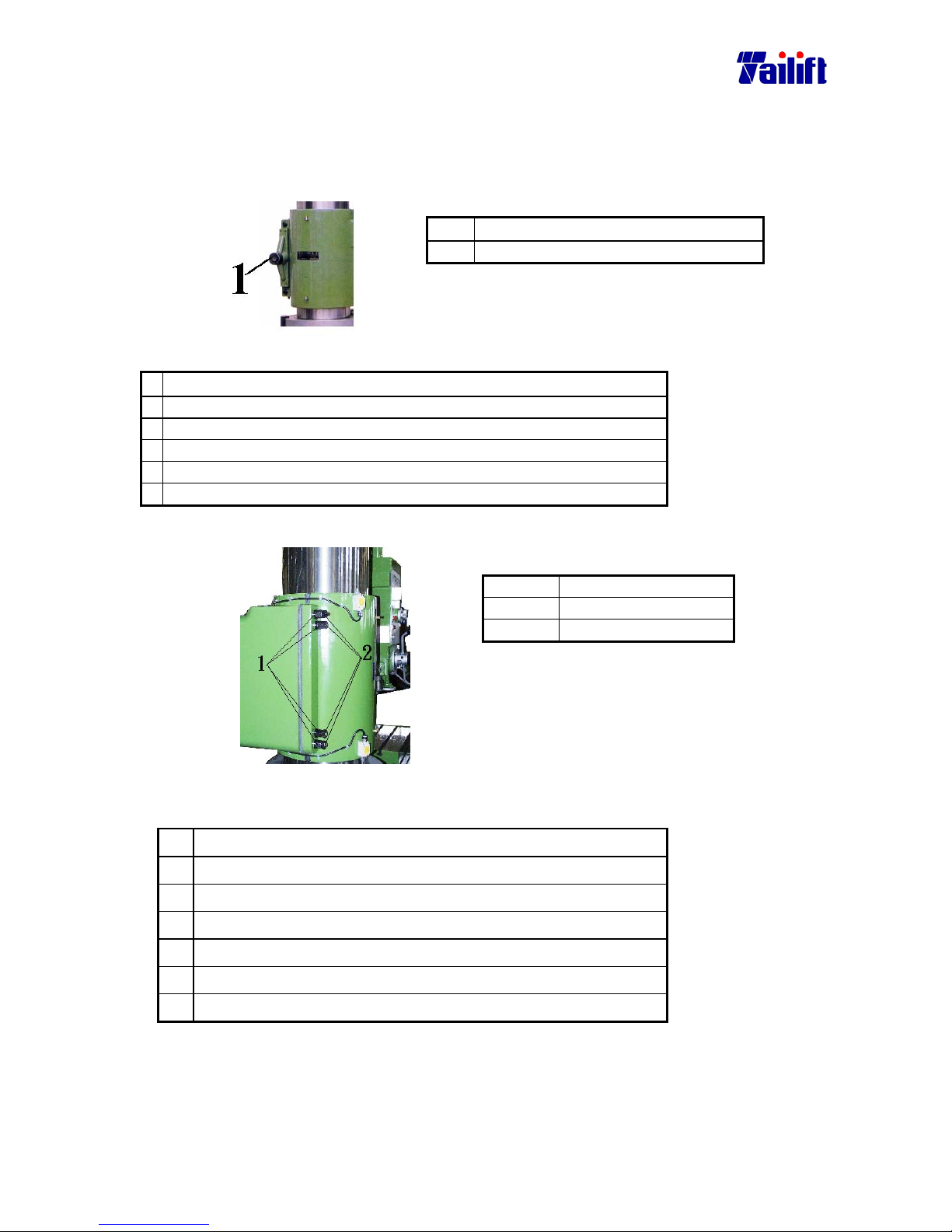
6-3
6.3 Adjust tighten the clamping device
After the machine has been used a period of time, the tighten the clamping device. It is the
time to adjust its tightness clamping device of adjusting nut.
6.3.1(For TPR-1230, TPR-1230H)
Part Name
1. clamping device of adjusting nut
Adjust tighten the clamping device lever as follows:
a. Switch the cross switch to ARM UP 。
b. Press the emergent stop button after the Arm elevates a little bit.
c. Release the clamping device and adjust the bolts and nuts.
d. Adjust the nut one notch clockwise.
e. Switch the cross switch to the middle.
f. Reset the emergent stop button.
6.3.2 (Application model: TPR-1600H, TPR-2000H)
position Name
1 Adjust the nut.
2 Fasten the nut.
The way to clamp the arm follows as:
a.
Turn the cross switch to ARM UP 。
b. After the arm lifts a little bit, press down the emergency stop.
c. Release the fastening nut.
d. Rotate the adjustment nut half circle clockwise.
e. Clamp the fastening nut.
f. Turn the cross switch to the middle.
g. Reset the emergency stop.
Page 59
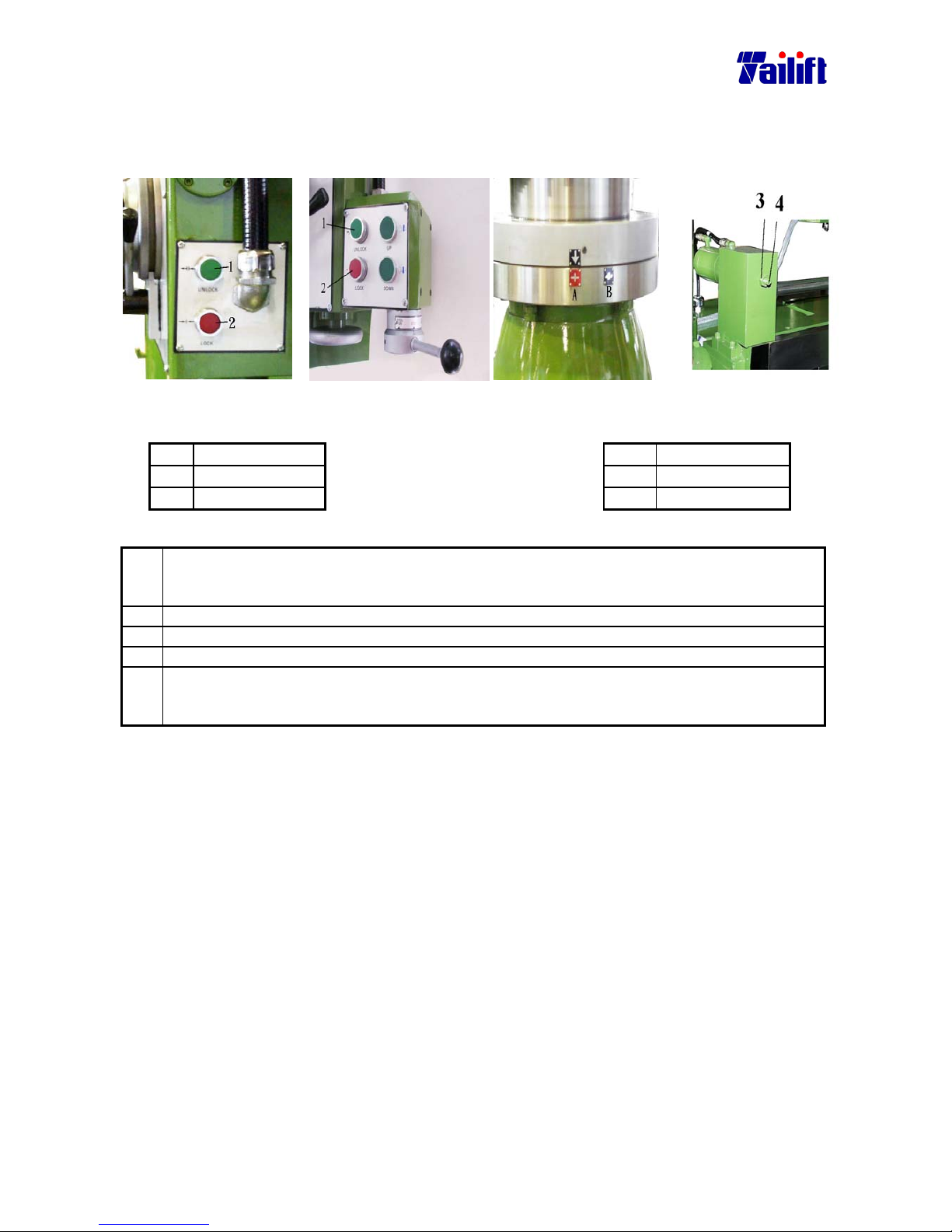
6-4
6.4 Adjust tighten the clamping device
After the machine has been used a period of time, the tighten the clamping device. It is the
time to adjust its tightness clamping device of adjusting nut.
6.4.1(For TPR-1230, TPR-1230H)
Fig a-1 Fig a-2 Fig b Fig c.
The relevant
names
The relevant names
No. Name No. Name
1. Release switch 3. Adjusting nut
2. Clamping switch 4. Fastening nut
Adjust tighten the clamping device lever as follows:
a. Press the button marked 1 in the below figure. Release the button only after you turn the
arrowhead to the point B, referring to the figure b. After the button released, the claming device
c
an be released.
b. Release the fastening nuts marked 3 in the figure 3.
c. Turn the adjusting bolts about 180° clockwise, using a spanner.
d. Tighten the fastening nuts marked 3 in the figure c.
e. Press the button marked 2 in the below figure a. Release the button only after you turn the
arrowhead to the point A, referring to the figure b. After the button released, the claming
device can be tightened.
Page 60
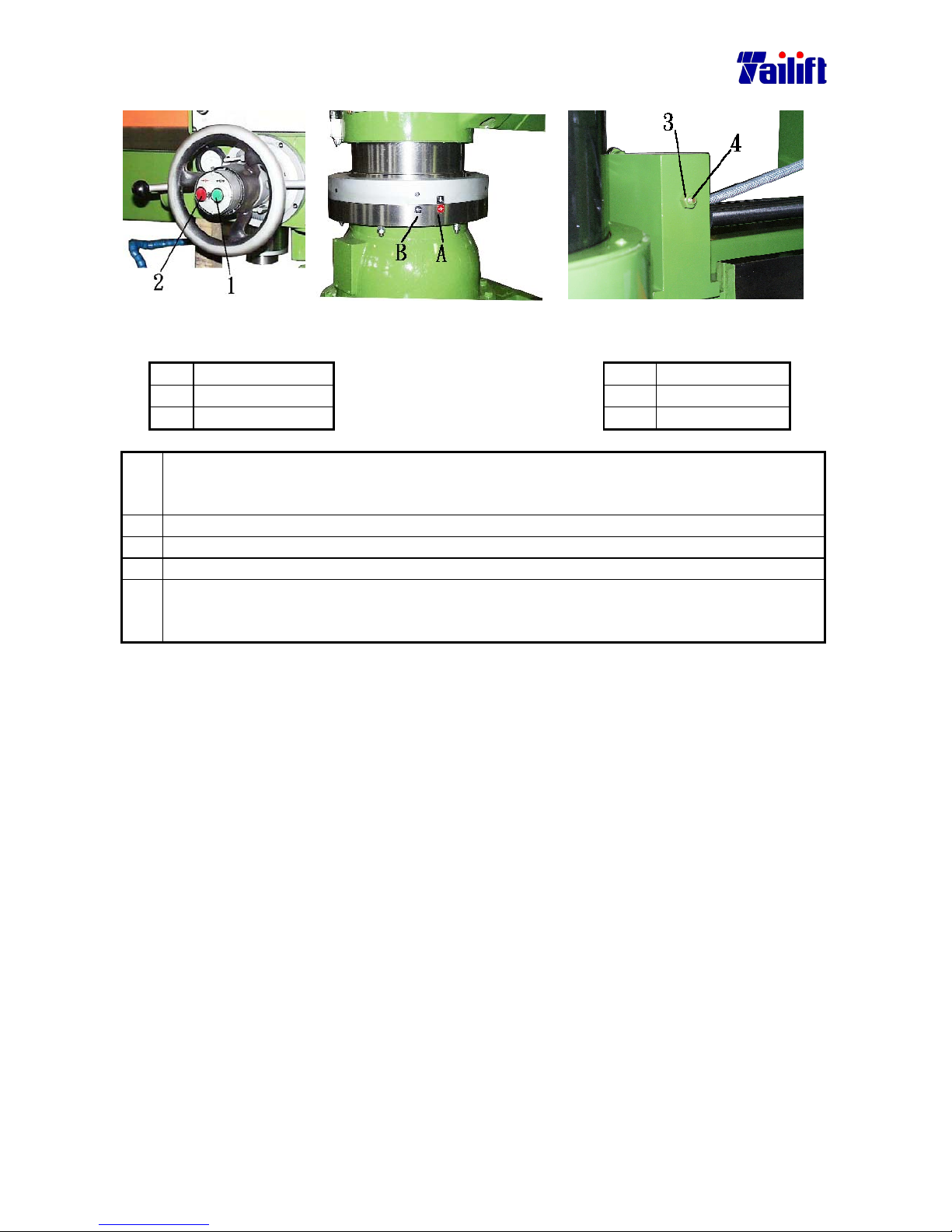
6-5
6.4.2(For TPR-1600H/ TPR-2000H)
Fig a. Fig b. Fig c.
The relevant
names
The relevant names
No. Name No. Name
1. Release switch 3. Adjusting nut
2. Clamping switch 4. Fastening nut
Adjust tighten the clamping device lever as follows:
a. Press the button marked 1 in the below figure. Release the button only after you turn the
arrowhead to the point B, referring to the figure b. After the button released, the claming device
c
an be released.
b. Release the fastening nuts marked 3 in the figure 3.
c. Turn the adjusting bolts about 180° clockwise, using a spanner.
d. Tighten the fastening nuts marked 3 in the figure c.
e. Press the button marked 2 in the below figure a. Release the button only after you turn the
arrowhead to the point A, referring to the figure b. After the button released, the claming
device can be tightened.
Page 61
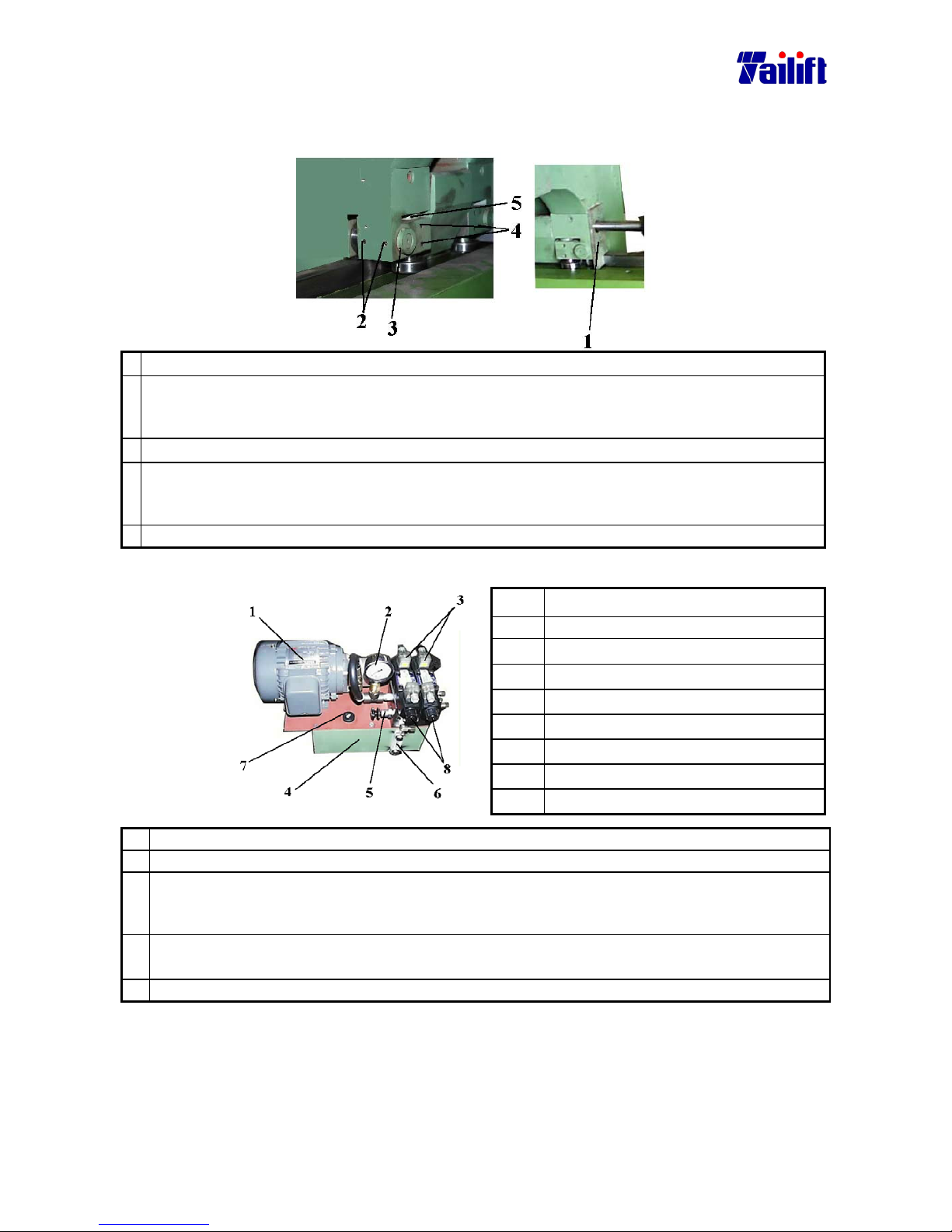
6-6
6.5 Adjustment of the backlash between the Gearbox and the Arm rail.
The backlash appears after the machine has been used for a period of time. It is necessary to
adjust the tightness between the Arm rail and crankshaft bearing.
a. Remove the side plate as the above figure 1.
b. Release the bolts as the above figure 2. Using socket wrench, insert it into the holes as
shown in the above figure 3 and rotate them. Apply the tightness as the hand wheel of the
Gearbox can be turned easily but not too easily. Apply the same to the counter side.
c. Release the bolts as shown in the right figure 4.
d. Using socket wrench, insert it into the holes as shown in the above figure 5 and rotate
them. Apply the tightness as the hand wheel of the Gearbox can be turned easily but not
too easily. Apply the same to the counter side.
e. Screw up the side plate of the above figure 1.
6.6Adjustment of the hydraulic pressure.
Parts Name
1. Hydraulic motor
2. Oil pressure gauge
3. Solenoid valve
4. Oil tank
5. Pressure adjusting valve
6. Oil gauge
7. Oil inlet
8. Forcible switch of the solenoid valve.
a. Please check that whether the hydraulic oil is sufficient?
b. Power on.
c. There is no pressure under the normal condition. If adjustment needed, please insert a
small screwdriver into the forcible switch of the solenoid valve, as shown in figure 8, to do
the adjustment.
d. Rotate the pressure adjusting valve, as shown in the figure 5, (clockwise to high and
counter clockwise to low pressure) The default pressure is 38bar(kg/cm2)。
e. Take out the screwdriver.
Precaution
When adjusting the hydraulic pressure, please keep pressing the forcible switch of the
solenoid valve continuously, as shown in the figure 8.
Page 62
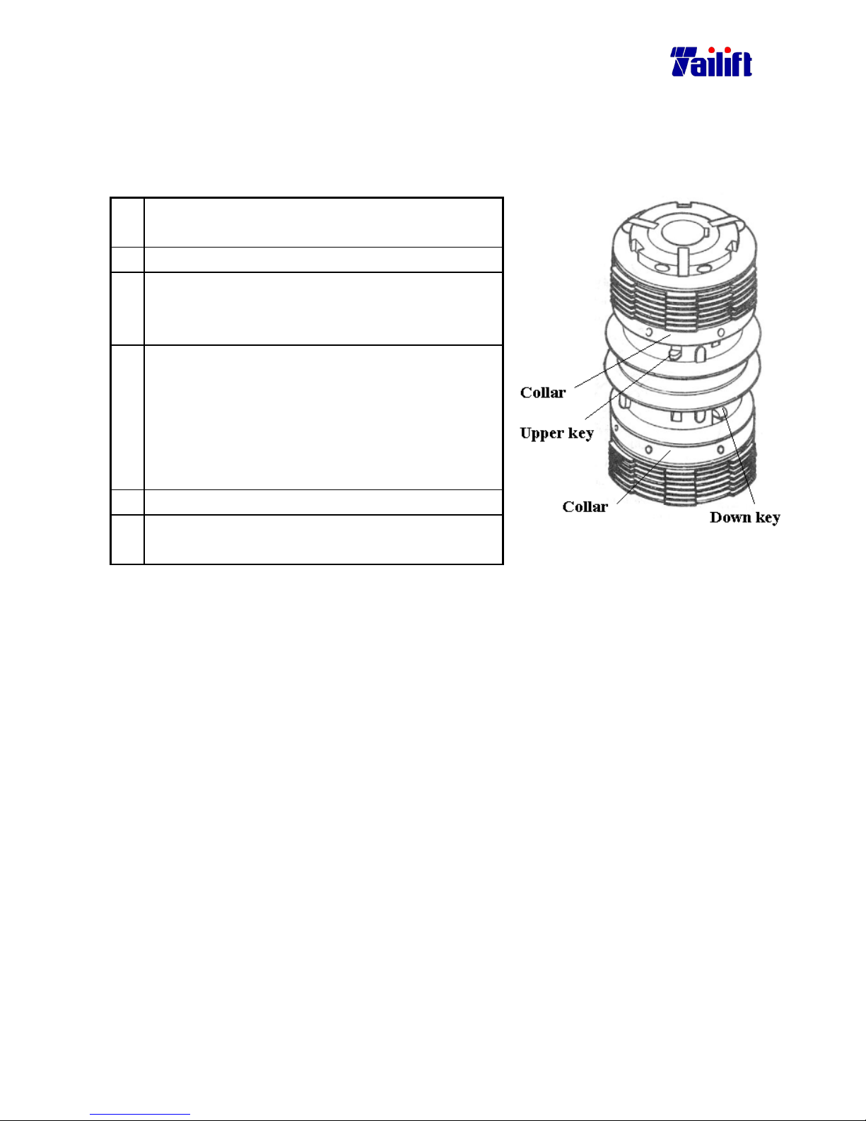
6-7
6.7 Adjustment of the clutch(for TPR-1600H/TPR-2000H)
While the spindle can’t rotate fully to drill, the clutch is wear to drill, the clutch is wear to
drill,the clutch is weared, you can adjust device, as following.
a. Change gear speed to the highest speed, turn off
power.
b. Remove oil sight glass.
c. Rotae spindle by your left-hand until clutch turns to
the best position for adjustment, clutch’s key faces
outside.
d. Push upper key(down key) out, turn collar
right(left) a little for adjustment, until the key
comes back notch automatically.
* If clutch “L”(“H”) speed can’t rotate fully while
drilling, you should adjust upper key
(down key)
e. Put oil sight glass.
f. Operate spindle to drill, check if sindle can rotate
while drilling.
Page 63
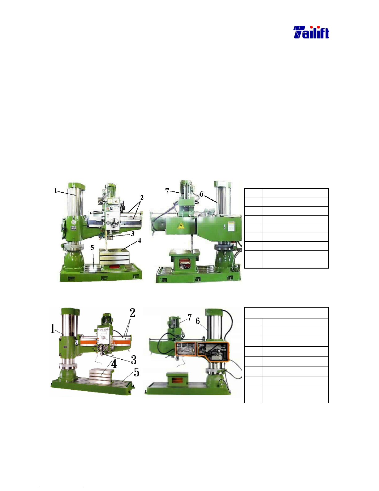
7-1
CHAPTER 7
Maintenance
7.1 General
Whether the machine is maintained well or not will lead to its long or short life. If well
served, the machine lasts long and is easy to maintain.
7.2 Daily Maintenance.
7.2.1 Clearing
Only one person is allowed to do the clearing. Before clearing, please power off.
7.2.2 Please clean every parts using a metal brush and a rag, dipped with oil,
to rub them.
(Please use CC68 )After every day’s work, please proceed the
following maintenance.。
(For TPR-1230, TPR-1230H)
The relevant names
No. Parts
1. Column
2. The arm rail
3. Spindle
4. Work table
5. The base
6. The ball screw
7. The counter weight
guide rail
(For TPR-1600H/ TPR-2000H)
The relevant names
No. Parts
1. Column
2. The arm rail
3.
Spindle
4.
Work table
5. The base
6.
The ball screw
7.
The counter weight
guide rail
Page 64
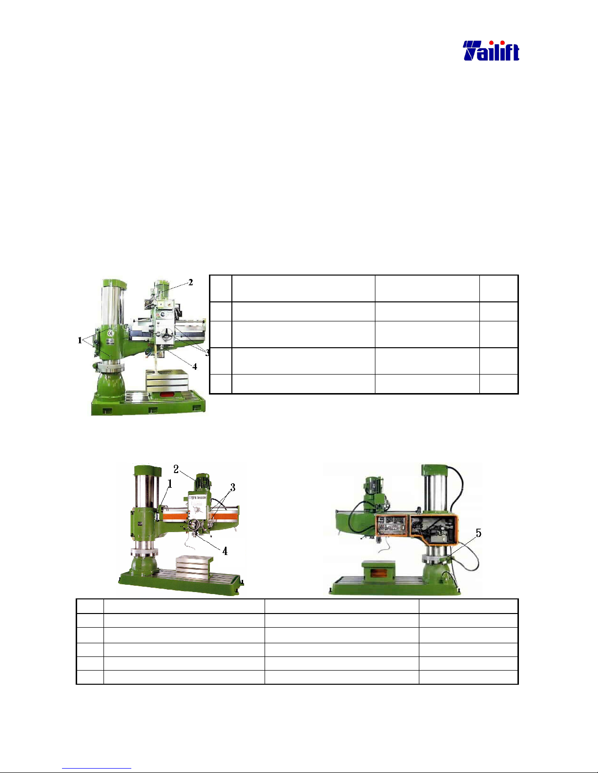
7-2
7.2.3 The way to clean iron filings:
1. Power off.
2. Put on gloves.
3. Clean from upside down using a brush.
4. When the iron filings comes down to the base, please collect it and put it at the right
side of the operation position.
5. Find a dustpan and place it under the machine.
6. Sweep it to the dustpan using the brush.
7. Rub every part of the machine with rags, particularly the parts where is
contaminated with the cutting fluids.
8. Rub every metal part of the machine using a oil-dipped rags.
7.2.4 Lubrication
Before every day’s work, please proceed the following maintenance.
(For TPR-1230, TPR-1230H)
No. Part Oil type Volum
e
1. Oil filler points of the column CC68 Full
2. Oil filler points on top of the
gearbox.
CC68 Full
3. Oil filler points in the right
side of the gearbox.
CC68 Full
4. Oil filler points of the spindle. CC68 Full
(For TPR-1600H/ TPR-2000H)
No. Part Oil type Volume
1. Column oil filler CC68 Full
2. Top gearbox oil filler CC68 Full
3. Left gearbox oil filler CC68 Full
4. Spindle oil filler XM2 Full
5. Clamping devise oil filler CC68 Full
Page 65
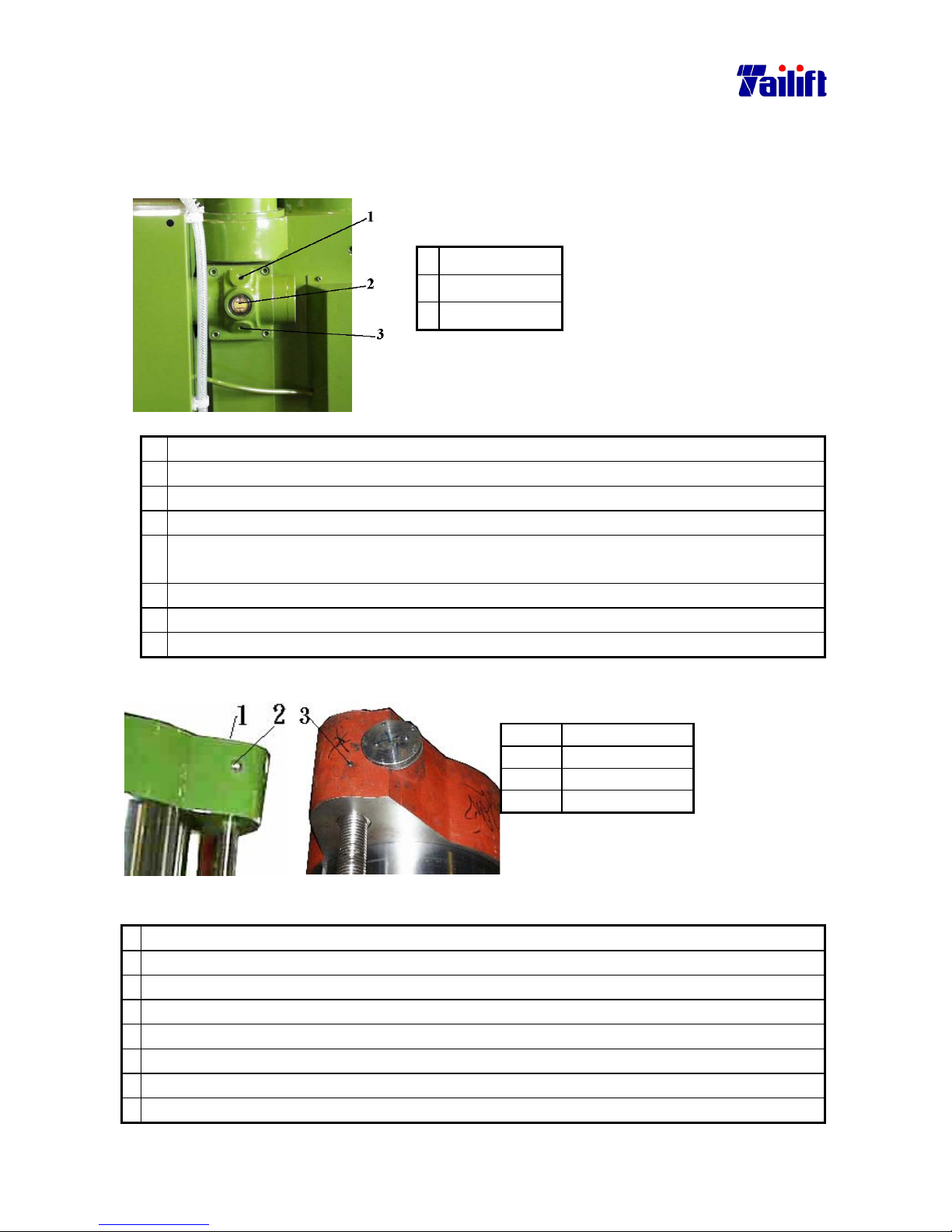
7-3
7.2.5 Change oil inside of the speed reduction of the arm elevating motor.
It requires only one person to do it. Please press down the emergent stop button and power off
before proceeding the job.
(For TPR-1230, TPR-1230H)
A. Instruction to the
relevant parts.
B. The following is the tools
to replace the oil.
1.
Oil filler points
Oil (CC68) 2 L
2.
Oil gauge
Container and spanner.
3.
Drain outlet
The steps:
1. Power off.
2. Press down the emergent stop button.
3. Place the container under the drain outlet.
4. Release the drain plug using a spanner.
5. After draining, tape the plug with a sheet of band and tighten it back to the drain
outlet.
6. Release the oil filler plug.
7. Add oil to the upper limit of the oil gauge.
8. Tighten the oil filler plug.
(For TPR-1600H/ TPR-2000H)
Instruction to the relevant parts.
No. Parts
1. Oil filler points
2. Oil gauge
3. Drain outlet
The following is the tools to replace the oil.
Oil (CC68)1 L
Container and spanner.
The steps:
1. Power off.
2. Press down the emergent stop button.
3. Place the container under the drain outlet.
4. Release the drain plug using a spanner.
5. After draining, tape the plug with a sheet of band and tighten it back to the drain outlet.
6. Release the oil filler plug.
7. Add oil to the upper limit of the oil gauge.
8. Tighten the oil filler plug.
Page 66
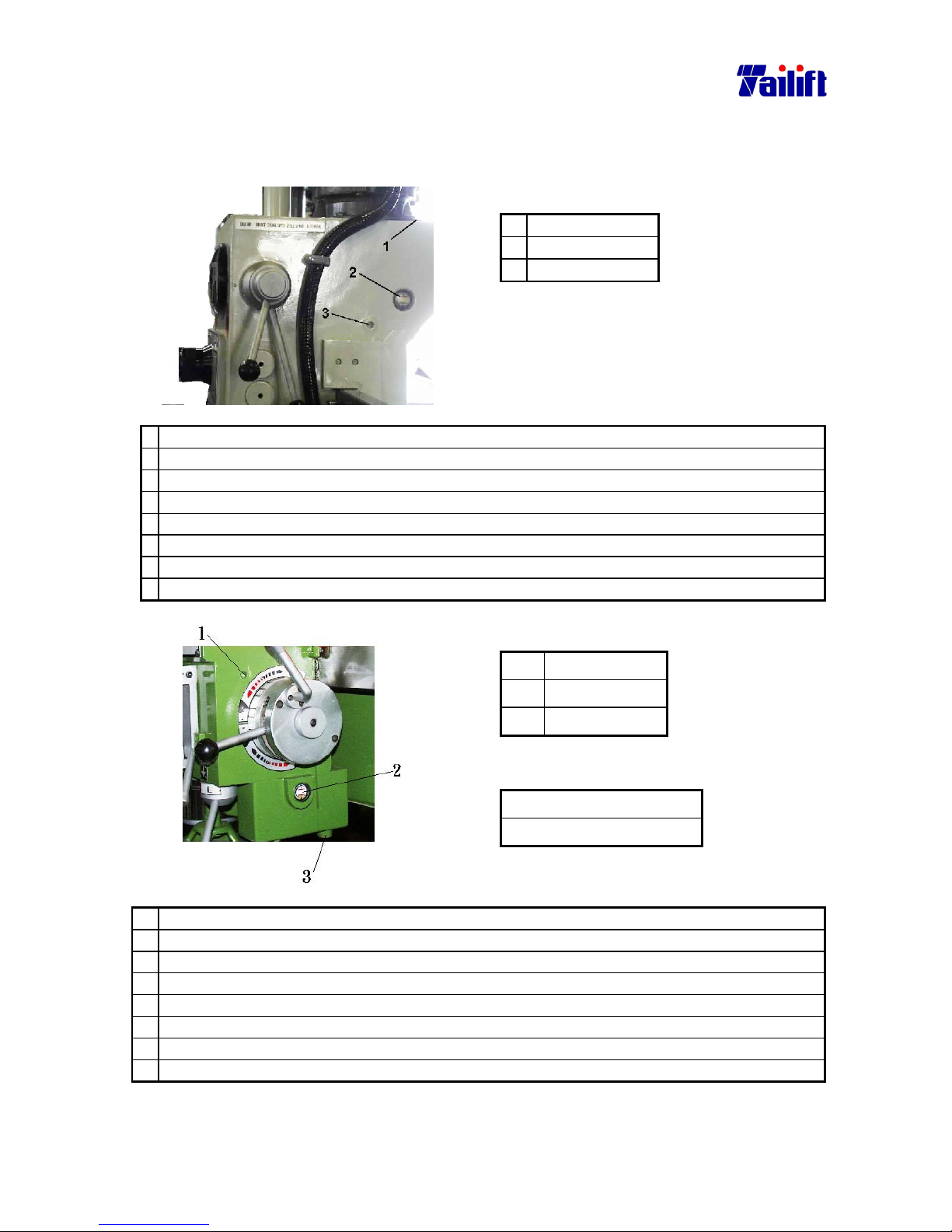
7-4
7.2.6 Chang the oil inside the gearbox.
It calls for only one person to do it. Please power off and press down the emergent stop button
before carrying out the job.
(For TPR-1230, TPR-1230H)
A. Instruction to the relevant parts.
1. Oil filler points
2. Oil gauge
3. Drain outlet
B. The following is the tools to replace the oil.
Oil(CC68) 4.5 L
Container and spanner.
The steps:
1. Power off.
2. Press down the emergent stop button.
3. Place a container under the oil drain outlet.
4. Release the drain plug using a spanner.
5. After draining, tape the plug with a sheet of band and tighten it back to the drain outlet.
6. Release the oil filler plug.
7. Add oil to the upper limit of the oil gauge.
8. Tighten the oil filler plug.
(For TPR-1600H/ TPR-2000H)
A. Instruction to the relevant parts.
1.
Oil filler points
2.
Oil gauge
3.
Drain outlet
B. The following is the tools to replace the oil.
Oil (CC68)3L
Container and spanner.
The steps:
1. Power off.
2. Press down the emergent stop button.
3. Place a container under the oil drain outlet.
4. Release the drain plug using a spanner.
5. After draining, tape the plug with a sheet of band and tighten it back to the drain outlet.
6. Release the oil filler plug.
7. Add oil to the upper limit of the oil gauge.
8. Tighten the oil filler plug.
Page 67
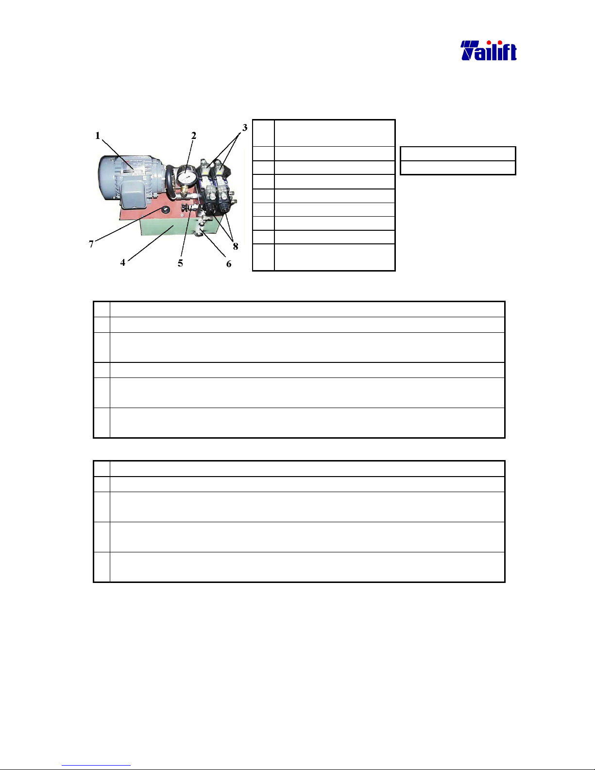
7-5
7.2.7 Changing hydraulic oil in the hydraulic oil pump.
(For TPR-1600H, TPR-1230H)
It requires only one person to operate it. Please power off and press down the emergent stop
before changing.
No Name The following is the
tools to replace the oil.
1. Hydraulic motor Oil (CB32)4.5L
2. Oil pressure gauge Container and spanner.
3. Solenoid valve
4. Oil tank
5. Pressure adjusting valve
6. Oil gauge
7. Oil inlet
8. Forcible switch of the
solenoid valve.
The steps to drain the oil follows as:
1. Power off.
2. Press down the emergent stop button.
3. Place the used oil container on the ground. Insert the outlet port of the oil-sucking
machine into the used oil container.
4. Turn off the inlet cover.
5. Insert the inlet port of the oil-sucking machine into the oil tank, to its bottom as
possible.
6. Power the oil-sucking machine on. After oil sucked completely, power the
oil-sucking machine off.
The steps to add oil follows as:
1.
Power off.
2.
Press down the emergent stop button.
3.
Place the hydraulic oil container on the ground. Insert the inlet port of the
oil-sucking machine into the hydraulic oil container.
4.
Insert the outlet port of the oil-sucking machine into the inlet port of the hydraulic
oil tank, about 50 mm deep.
5.
Power the oil-sucking machine on. Power it off when the oil gauge reaches its upper
limit level.
Page 68
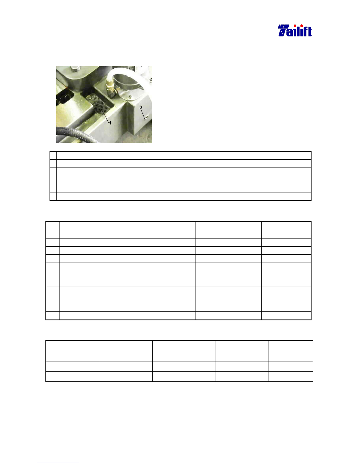
7-6
7.3 Replace the cutting fluids.
It requires only one person to do it. Please power off and press down the emergent stop
power button before carrying out the job.
A. Instruction to the relevant parts.
1. Oil filler points
2. Oil drain outlet
B. The following is the tools to replace the cutting
fluids.
The cutting fluids 30L
Container and spanner
The steps:
1. Power off.
2. Press down the emergent stop button.
3. Place a container under the oil drain outlet.
4. Release the drain plug using a spanner.
5. After draining, tape the plug with a sheet of band and tighten it back to the drain outlet.
6. Refill the cutting fluids through the oil filler inlet to the level under 5 mm under the oil filter.
7.4
Maintenance and replacement period.
No. Position Items. Period
1. Oil filler points of the column CC68 once per day.
2. Oil filler points on top of the gearbox CC68 once per day.
3. Oil filler points in the right side of the gearbox. CC68 once per day.
4. Oil filler points in the left side of the gearbox. CC68 once per day.
5. Oil filler points of the spindle XM2 once per day.
6 Replace oil for the speed reduction of the arm
elevating motor.
CC68 once per year.
7 Change oil inside of the gearbox. CC68 once per year.
8 Chang the cutting fluids. The cutting fluids Once per month
9 The arm transmit ion ball screw XM2 Once per week
10. Replace the hydraulic oil CB32 once per year.
A suitable Oil Type comparison:
ISO DIS-3498 SHELL MOBIL ESSO CHINA
CB32 TELLUS C32 DTE OLL LIGHT TERESSO 32 R32
CC68 OMALA 68 MOBILGEAR 620 SPARTAN EP68 HD68
XM2 ALVANIA R2 MOBILUX 2 BEACON 2 #2
7.5 Waste disposition.
Please proceed waste disposition such as machine oil, iron filings, old machine or replaced
parts according to your country’s relevant legal regulation.
Page 69
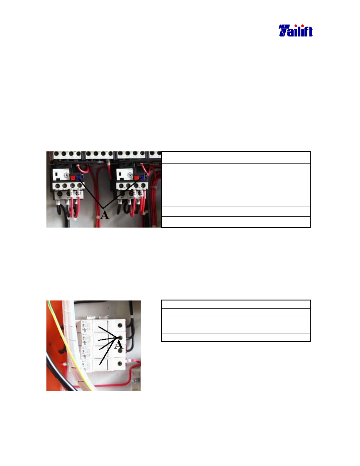
8-1
CHAPTER 8
Troubleshooting
8.1 The spindle overloads and the relay jumps.
8.1.1 The cause.
a. The drill bit is too big.
b. The feed rate is too fast.
c. Operation not in compliance with speedometer and the automatic feed rate table.
d. The fuse burned out.
e. The voltage is too low.
8.1.2The solution
a. Power off.
b. Open the control box.
c. Press the relay switch to open, as shown in the
right picture, three minutes after the spindle
stops. (blue Button)
d. Close the control box.
e. Power on.
8.2 The spindle overloads and the fuse burns out.
8.2.1 The cause
a. The drill bit is too big.
b. The feed rate is too fast.
c. Operation not in compliance with speedometer and the automatic feed rate table.
8.2.2 The solution.
a Power on.
b Open the control box.
c Replace the fuse as shown in the picture A.
d Close the control box.
e Power on.
Page 70

8-2
8.3
What if the drill bit get broken?
a. Stop the spindle.
b. Press down the emergent stop button.
c. Push the gearbox backwards.
d. Pinch the end of the broken bit with a pliers.
e. Rotate counter clockwise and pull it out upwards.
8.4 What if the screw tap get broken?
a. Stop the spindle.
b. Press down the emergent stop button.
c. Using thread releaser, rotate the screw tap counter clockwise till it comes out. If it
is impossible to pull it out, you may think to melt it out with EDM or declare it
unusable.
8.5 How if a person is entangled?
a.
Press down the emergent stop button.
b.
Power off.
c. Switch the speed change lever to the highest gear.
d. Rotate the spindle with hands counter clockwise (if the spindle moved clockwise
before, then its reverse direction is counter clockwise now) till that the person is
free from the machine.
Page 71
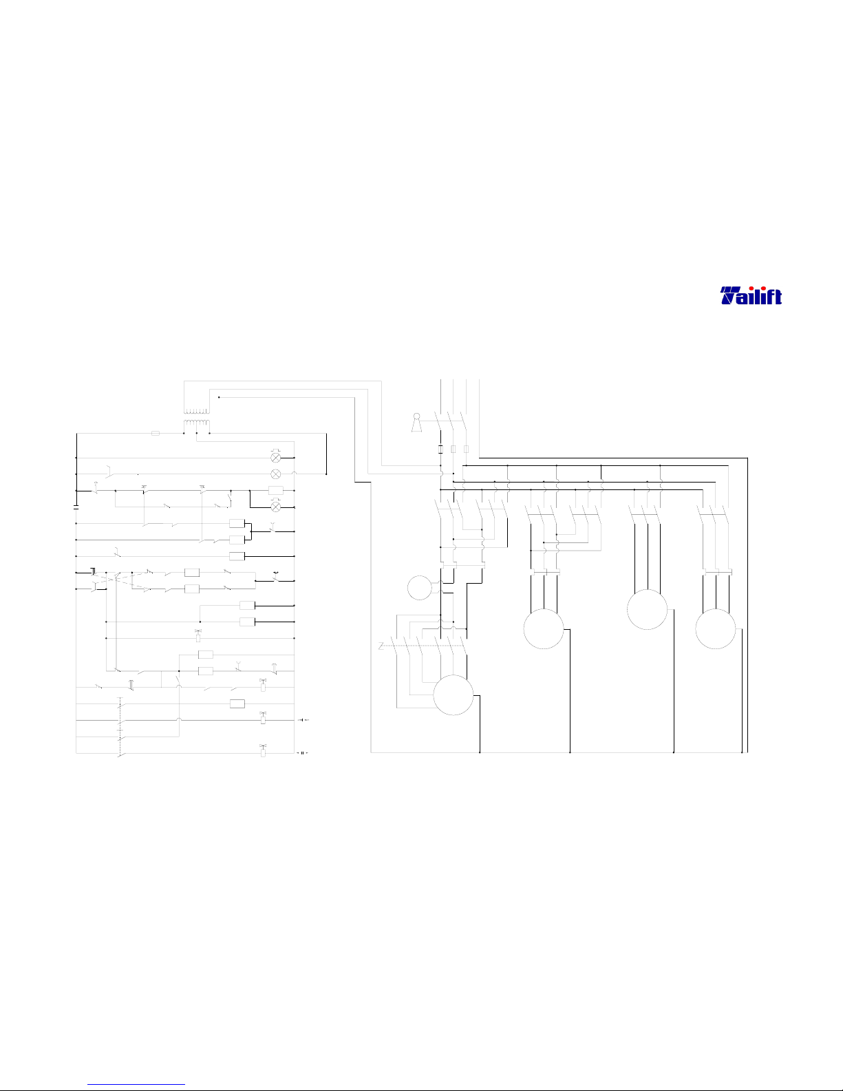
9-1
CHAPTR 9 Annex
9.1 Electrical circuit diagram
(For TPR-1230H CE Standard)
2
1.25mm
2
2
2
2
Power
U,V,W
U3,V3,W3
2
2mm
1.25mm
1.25mm
2
2
A
2mm
0.75Kw
Elevator
Motor
M2
Motor
2.25Kw
2mm
M1
3~
2mm
2mm
2
2mm
2
Main
2mm
2
~
2mm
2
2mm
22
1.25mm
2
2
2mm
3~
2mm
2
2
2mm
2
M4
0.1Kw
Coolant Pump
Motor
3~
2mm
L13
L23
FU3
2mm
2
M1
L11
L21
FU1
L12
L22
FU2
2
2mm
2
OL1
M2
M3
3.5mm
Key Switch
3.5mm3.5mm
22
L1 L2
2
3.5mm
2
PE
L3
2mm
OL2
2mm
2
2
2mm
2
M4
2mm
2
2
2mm
1.25mm
M5
2
U
1.25mm1.25mm
W
22V2
W1
V1
U1
2mm
2
Hydraulic
0.75Kw
Motor
3~
M3
2
2mm
2mm
2mm
2
2
M6
OL3
SS6
U2 V2 W2
U3 V3 W3
SS4
1.2.3(Low)
4.5.6(High)
29
31
M3
PB2
PB3
30
29
27
24
25
T1
CR1
15
15
21
T2
CR1
M6
CR2
25
29
CR2
26
(28)
CR2
SOL1
22
M4
LS5
23
15
SOL4
Elevating
U1,V1,W1
T2
SOL3
SOL2
28
32
T1
DOWN
M0
1.25mm
1.25mm
110V
1
0V
1.25mm
2
1
24V
LS1
1.25mm
M4
SS2
LS3
15
14
16 17
8
SS1
3
SS3
FU4
76
1.25mm
1.25mm
10
1.25mm
18
2
M5
9
2
M2
M2
LS4
19
M5
11
2
M1
M1
SS1
4
2
LS2
5
400V
TR
E
150VA
23
2
1.25mm
(Alarm Lamp)
Work Lamp
Pump Motor
Elevating
OL2
OL1
12
Coolant
UP
Spindle
Reverse
Forward
Spindle
M0
2
1.25mm
1
PB1
SS5
LS6
13
2
M0
1
20
U2,V2,W2
CR1
OL3
Page 72
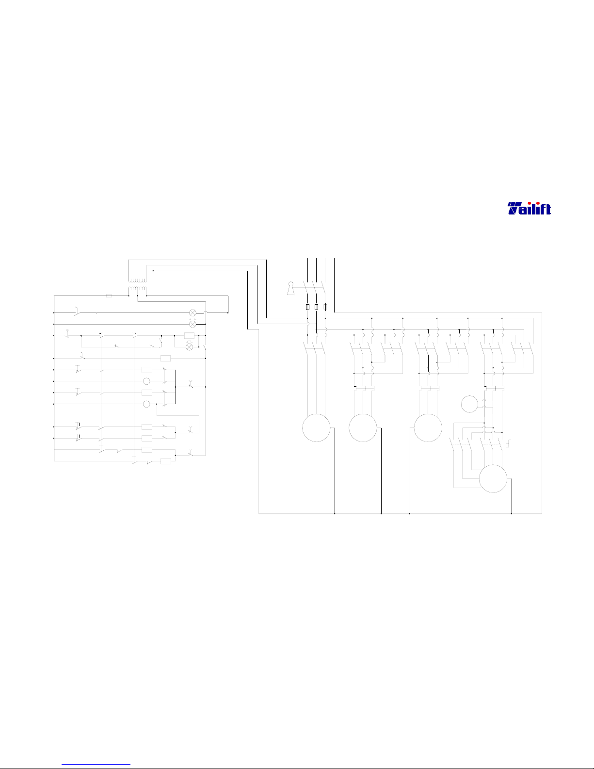
9-2
9.2 Electrical circuit diagram
(For TPR-1230 CE Standard)
PB3
1
1
Down
23
MS5
11
MS7
SS2
12
MS7
MS6
MS6
SS2
(12)
13
(13)
Main Motor
24
OL3
Reverse
Forward
15
U3,V3,W3
MS1
LS1
PB2
MS5
SS5
SS2
10
9
(11)
(10)
MS4
MS2
(9)
PB1
8
SS1
7
MS3
(8)
LS4
MS4
MS3
LS6
LS5
22
PL
PB1
20
19
MS2
9
3
PB1
PL
18
LS2
17
4
LS2
M01
2
SS3
SS2
1
1
FU4
150VA
TR
6
SS2
24V
0V
5
110V
220V 380V
E
M0
Elevator Motor
Clamp Motor
Pump Motor
21
OL2
20
Up
Release
16
OL1
Clamp
15
M02
Coolant
U1,V1,W1
U2,V2,W2
U,V,W
(Alarm Lamp)
Work Lamp
Power
2
1.25mm
2
2mm
2
1.25mm
2
23
3~3~3~
Coolant Pump
Motor
0.1Kw
2
1.25mm
Motor
0.75Kw
Clamp
0.75Kw
Motor
Elevator
2
2mm
2mm
2
2mm
1.25mm
M1
U
1.25mm
V
2
MS1
W
2
1.25mm
2
M2
2mm
U1
V1
2
2
2mm
MS2
FU3
3.5mm
L13L11 L12
FU1 FU2
Key Switch
3.5mm23.5mm
2
L1 L2
2
3.5mm
2
PEL3
M3
2mm
U2
OL1
W1
2
MS3 MS4
OL2
2
V2
2mm
2
W2
2
2mm
~
A
MS5
3~
Main
2.25Kw
Motor
2
3.5mm
M4
SS4
OL3
3.5mmU33.5mm
V3
2W32
3.5mm
2
MS6 MS7
1.2.3(Low)
4.5.6(High)
Page 73
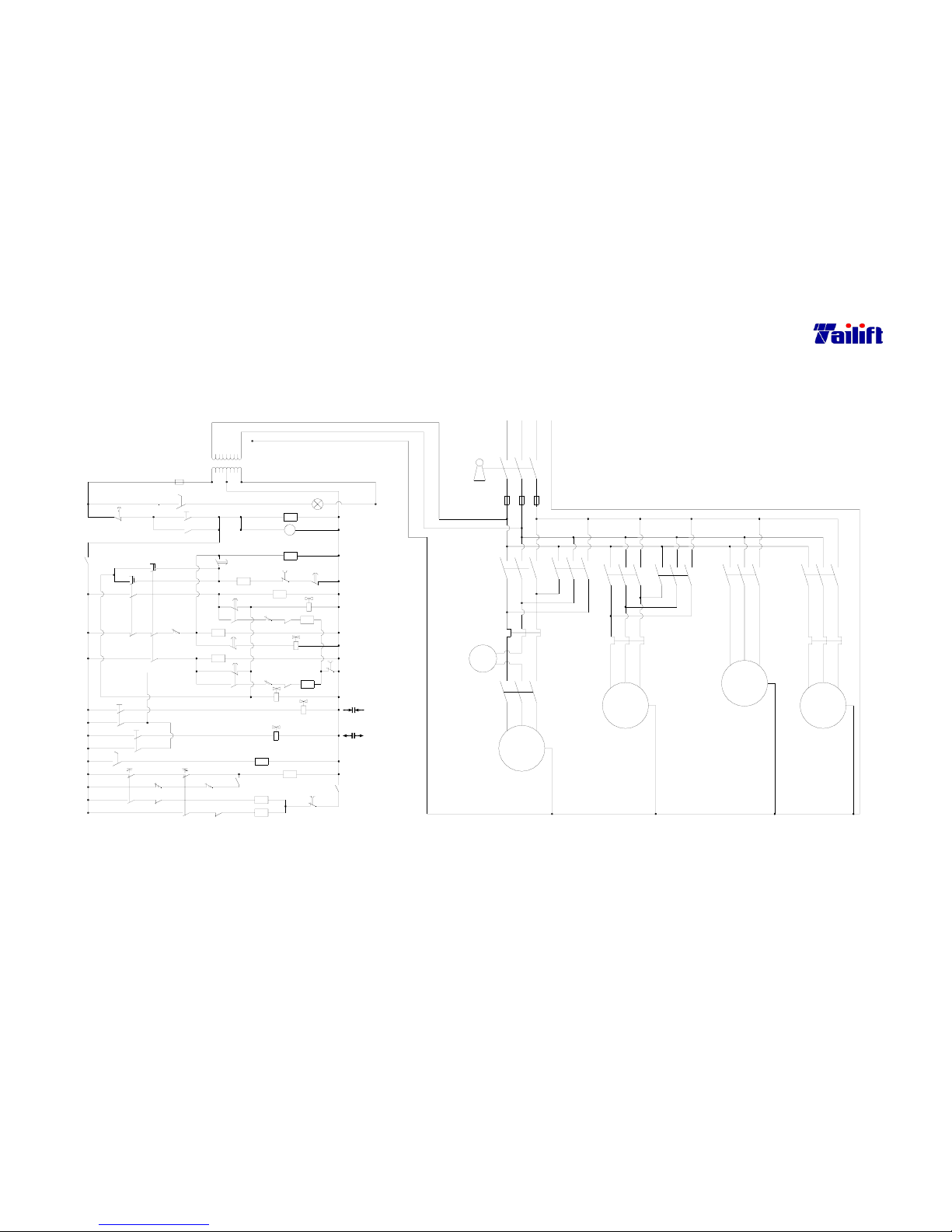
9-3
9.3 Electrical circuit diagram
(For TPR-1600H CE Standard)
MS1-1
LS4
PB3 23
SS2
30
SS3
25
6
PB3
6
22
To MS5
CR2-1
26
27
31
32
SS3
33
MS2-1
28
LS5
17
T3
T3
T3
18
9
SOL4
CR2
MS1
MS2
MS6
34
OL1
29
CR2-2
SOL5
12
MS4-1
9
LS2
11
SOL3
MS3
OL2
CR1-2
5
8
15
PB1
4
1
3
110V
24V
0V
FU4
MS5
T4-1
LS3
14
15
17
9
T1
T2-2
T2
16
10
T1
8
6
CR1-1
PB2
1
SS1
1
15
12
MS3-1
SOL1
LS1
SOL2
11
7
T1
OL2
MS4
35
T2
2
CR1
PB2
T4
PL
380V
500VA
TR
220V
E
3.5mm
2
V3
W3
U3
3~
M1
5.625Kw
Motor
Main
Coolant Pum p Motor
Forward
U3, V3, W3
Reverse
U, V, W
U2, V2, W2
Down
~
M1
A
U2
3~
Motor
Elevator
1.5Kw
M2
2
5.5mm
2mm
2
V2
W2
L2
5.5mm
FU3
Up
Hydraulic Motor
U1, V1, W1
Work Lamp
2
35
MS1
L11
FU1
L12
FU2
Key Switch
5.5mm 5.5mm
22
L1
OL1
MS2
MS3
L13
OL2
MS4
5.5mm
22
L3 PE
0.1Kw
2mm
2
3~
Coolant Pump
M4
Motor
Hydraulic
0.5mm
Motor
0.75Kw
2
M3
3~
V
U
W
MS6
U1
MS5
V1
W1
OL3
4
Page 74
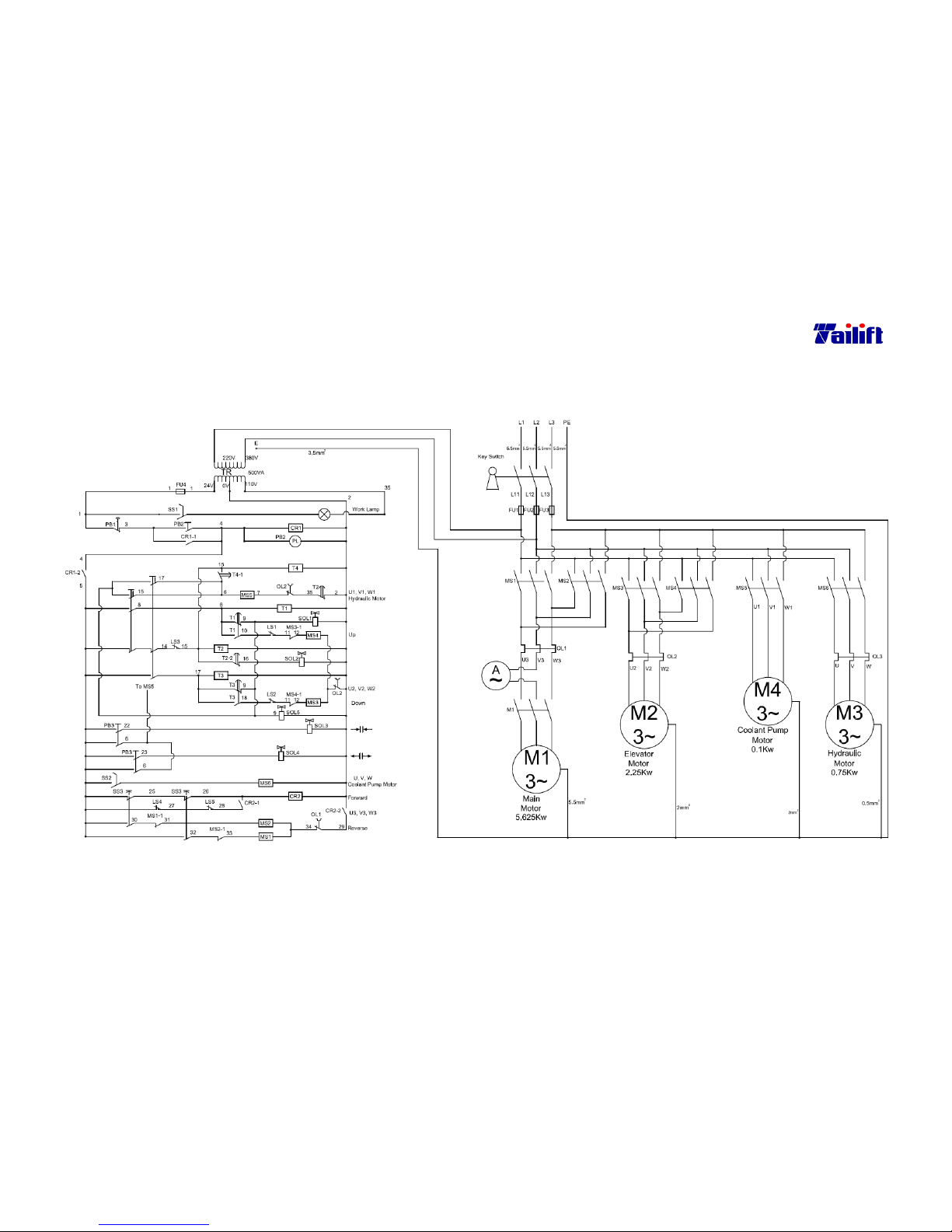
9-4
9.4 Electrical circuit diagram
(For TPR-2000H CE Standard)
Page 75
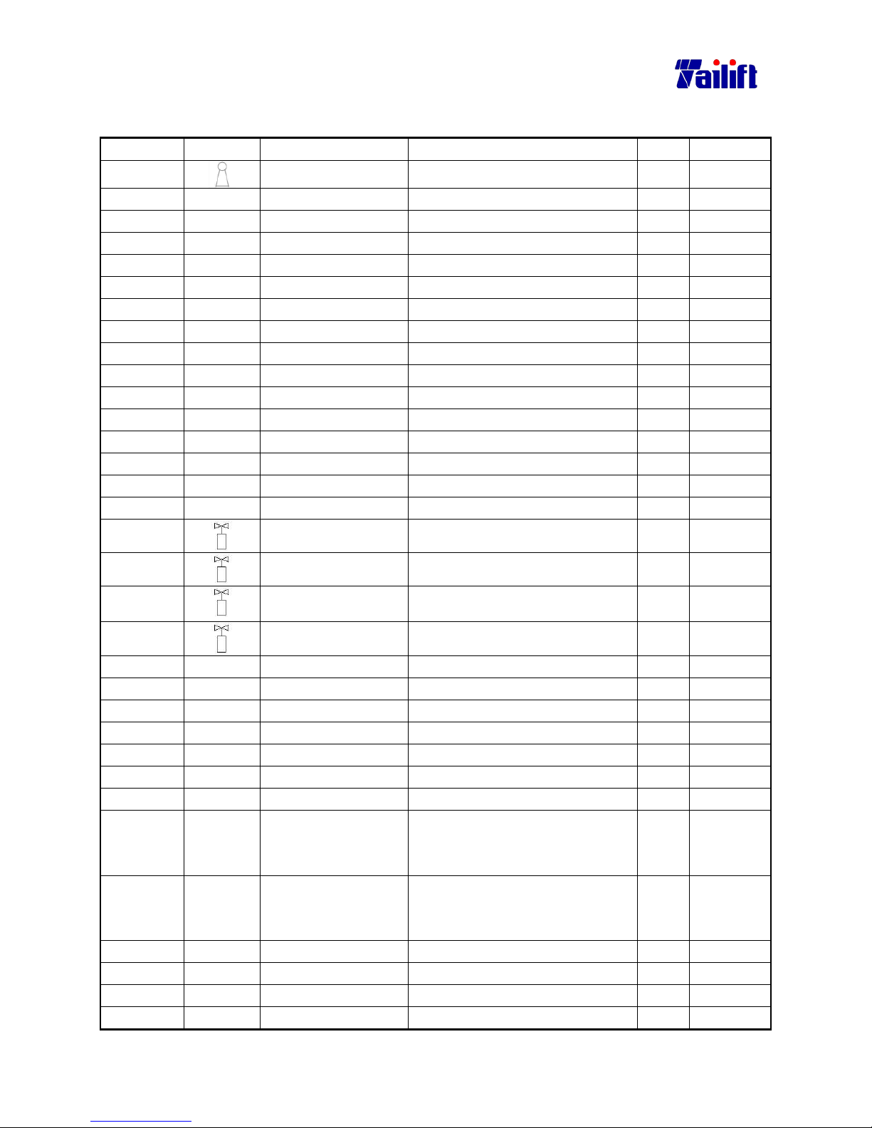
9-5
9.5 Electrical main parts list (for TPR-1230H CE Standard)
Part No. Symbol Name Specification Q’ty Remark
E1602001
Key Switch XF163B 1
E0703005 M1 Magnetic Contact CU18 24V 1
E0703005 M2 Magnetic Contact CU18 24V 1
E0703004 M3 Magnetic Contact CU11 3a1b 24V 1
E0703004 M4 Magnetic Contact CU11 3a1b 24V 1
E0703004 M5 Magnetic Contact CU11 3a1b 24V 1
E0703004 M6 Magnetic Contact CU11 3a1b 24V 1
E0703004 M0 Magnetic Contact CU11 3a1b 24V 1
E3101027 FU1 Fuse 10*38*20A 1
E3101027 FU2 Fuse 10*38*20A 1
E3101027 FU3 Fuse 10*38*20A 1
E3101025 FU4 Fuse 10*38*6A 1
E0211001 CR1 Control Relay MK-2P 24V 1
E0211001 CR2 Control Relay MK-2P 24V 1
E0208001 T1 Timer Relay ASTP-N 24V 6S 1
E0208001 T2 Timer Relay ASTP-N 24V 6S 1
M0302019
SOL1 DSG-3C2-02-24V 1
M0302019
SOL2 DSG-3C2-02-24V 1
M0302019
SOL3 DSG-3C2-02-24V
1
M0302019
SOL4 DSG-3C2-02-24V
E0207017 OL1 Overload relay RHN 10/5.5~8.5 1
E0207018 OL2 Overload relay RHN 10/1.8~2.7 1
E0207018 OL3 Overload relay RHN 10/1.8~2.7 1
E0901021 SS1 Limit Switch V-15-1E5 4
E1303002 SS2 Selector Switch
YK∅30 1A1B (B)
1
E1604001 SS3 Selector Switch SN1021 1
E1603001 SS4 Pole change Switch A441 CA10 1
B100012 SS5 Push Button ZB4-BA2
ZB4-BZ101
ZBE-102
1
B100012 SS6 Push Button ZB4-BA2
ZB4-BZ101
ZBE-102
1
E1203001 PB1 Emg. Push Button
YK∅30 1A1B
1
E1202012 PB2 Push Button
YK∅22 2A (B)
1
E1202012 PB3 Push Button
YK∅22 2A (B)
1
E0901006 LS1 Limit Switch MJ2-1308R 1
Page 76
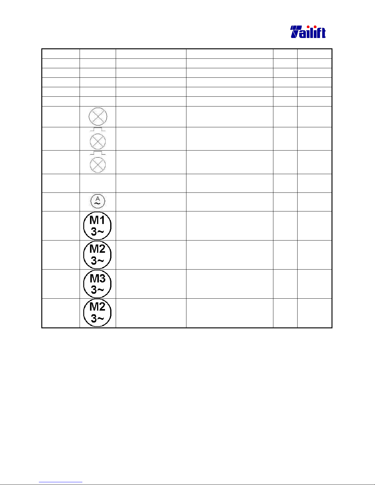
9-6
Part No. Symbol Name Specification Q’ty Remark
E0901008 LS2 Limit Switch TZ 8104 1
E0901009 LS3 Limit Switch MN 5311 1
E0901011 LS4 Limit Switch AZ 7121 1
E0901010 LS5 Limit Switch WLD2 1
E0901009 LS6 Limit Switch MN 5311 1
E1701002
Work Lamp FS 51441 110V 1
E2305001
Power (Alarm Lamp)
YK∅30 24V(W)
1
E2305001
Power (Alarm Lamp)
YK∅30 24V(W)
1
E1801020 TR Transformer 150VA
1:0,220,380 2:0,24,110
1
E3602002
AMP Meter S065 20A 1
Main Motor 2.25KW/1.5Kw
200/400V/4P/8P/3PH
1
Elevating Motor 0.75KW 200/400V/4P/3PH 1
Hydraulic Motor 0.75KW 200/400V/4P/3PH 1
Coolant Pump Motor 0.75KW 200/400V/2P/3PH 1
Page 77
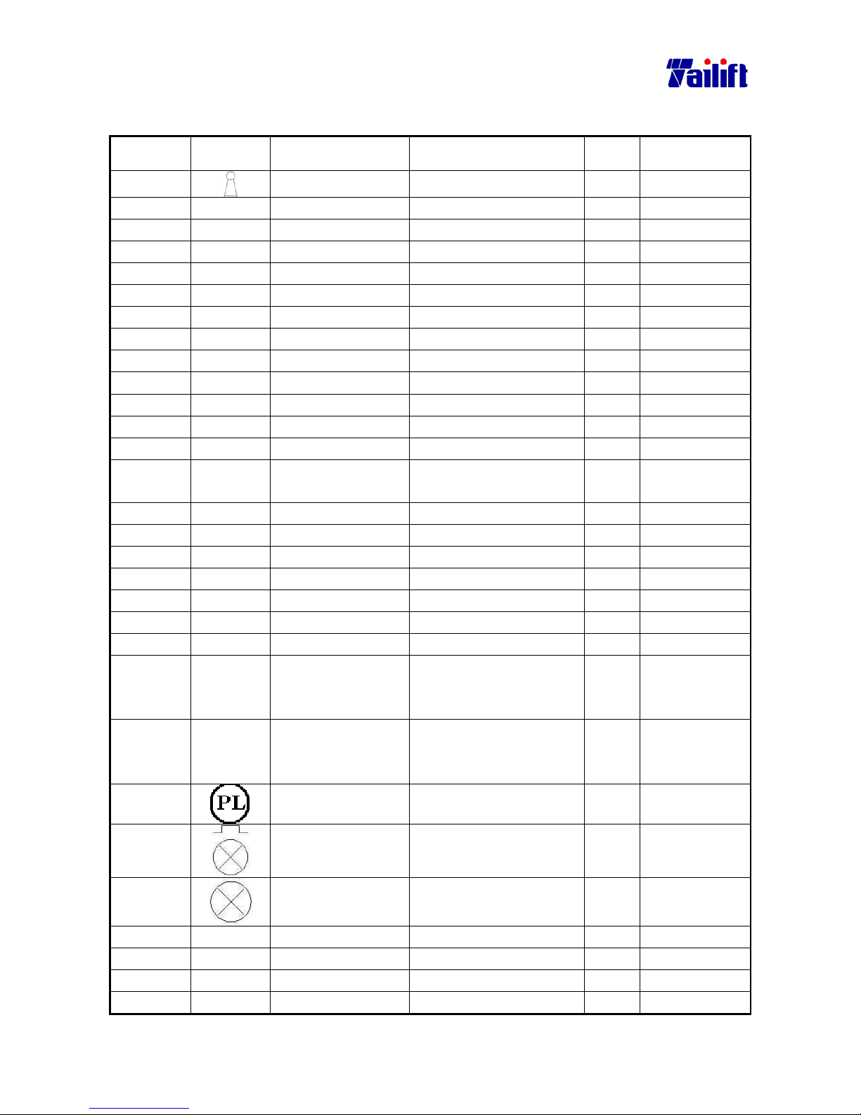
9-7
9.6 Electrical main parts list (for TPR-1230 CE Standard)
Part No. Symbol Name Specification Q’ty Remark
E1602001
Key Switch XF163B 1
E0703004 M0 Magnetic Contact CU11 3a1b 24V 1
E0703004 MS1 Magnetic Contact CU11 24V 1
E0703004 MS2 Magnetic Contact CU11 3a1b 24V 1
E0703004 MS3 Magnetic Contact CU11 3a1b 24V 1
E0703004 MS4 Magnetic Contact CU11 3a1b 24V 1
E0703004 MS5 Magnetic Contact CU11 3a1b 24V 1
E0703005 MS6 Magnetic Contact CU18 24V 1
E0703005 MS7 Magnetic Contact CU18 24V 1
E3101027 FU1 Fuse 10*38*20A 1
E3101027 FU2 Fuse 10*38*20A 1
E3101027 FU3 Fuse 10*38*20A 1
E3101025 FU4 Fuse 10*38*6A 1
E1801020 TR Transformer 150VA
1:0,220,380 2:0,24,110
1
E0207018 OL1 Overload relay RHN 10/1.8~2.7 1
E0207018 OL2 Overload relay RHN 10/1.8~2.7 1
E0207017 OL3 Overload relay RHN 10/5.5~8.5 1
E1303002 SS1 Selector Switch
YK∅30 1A1B(B)
1
E0901021 SS2 Limit Switch V-15-1E5 4
E1604001 SS3 Selector Switch SN1021 1
E1603001 SS4 Pole change Switch A441 CA10 1
B100012 SS5 Push Button ZB4-BA2
ZB4-BZ101
ZBE-102
1
B100012 SS6 Push Button ZB4-BA2
ZB4-BZ101
ZBE-102
1
E2305001
Pilot
YK∅30 24V(W)
1
E2305001
Power (Alarm
Lamp)
YK∅30 24V(W)
1
E1701002
Work Lamp FS 51441 110V 1
E0901006 LS1 Limit Switch MJ2-1308R 1
E0901008 LS2 Limit Switch TZ 8104 1
E0901007 LS3 Limit Switch MJ2-1704 1
E0901007 LS4 Limit Switch MJ2-1704 1
Page 78
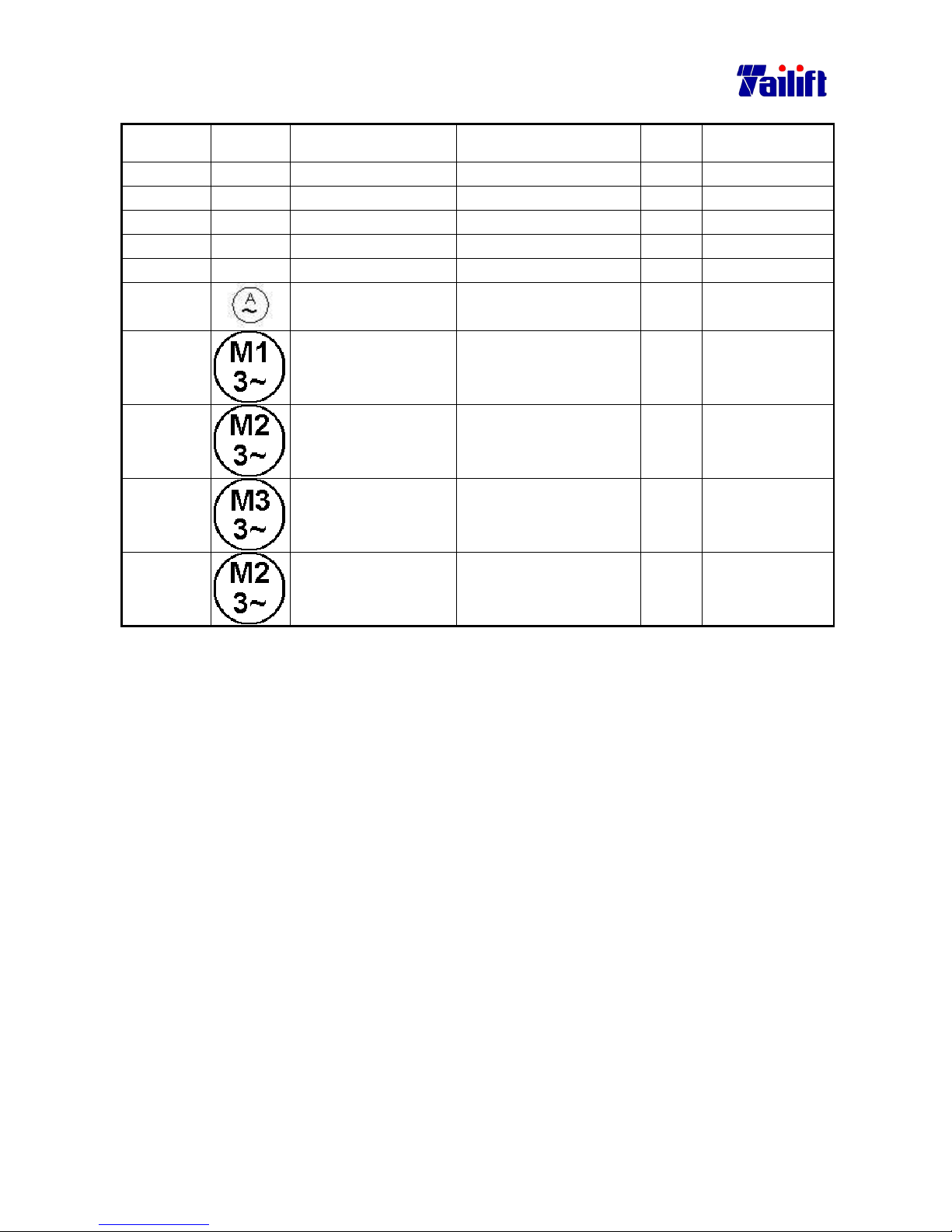
9-8
Part No. Symbol Name Specification Q’ty Remark
E0901007 LS5 Limit Switch MJ2-1704 1
E0901007 LS6 Limit Switch MJ2-1704 1
E1202002 PB1 Push Button
YK∅22 24V (R)
1
E1202001 PB2 Push Button
YK∅22 24V (G)
1
E1618003 PB3 Emg. Push Button
YK∅30 1B
1
E3602002
AMP Meter S065 20A 1
Main Motor 2.25KW/1.5Kw
200/400V/4P/8P/3PH
1
Elevating Motor 0.75KW
200/400V/4P/3PH
1
Hydraulic Motor 0.75KW
200/400V/4P/3PH
1
Coolant Pump Motor 0.75KW
200/400V/2P/3PH
1
Page 79
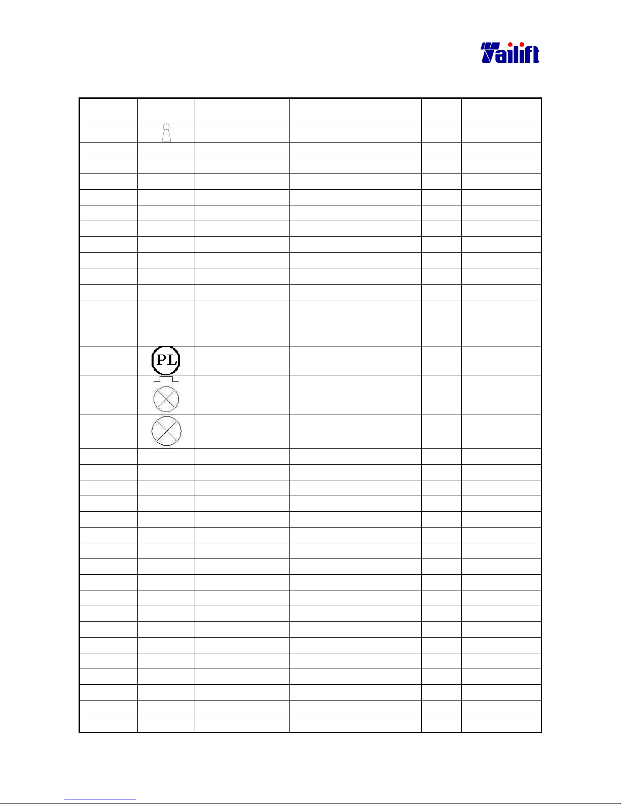
9-9
9.7 Electrical main parts List (for TPR-1600H CE Standard)
Part No. Symbol Name Specification Q’ty Remark
E1602002
Key Switch XF323B 1
E3101023 FU4 Fuse 10*38*6A 1
E0703006 MS1 Magnetic Contact CU27 24V 1
E0703006 MS2 Magnetic Contact CU27 24V 1
E0703004 MS3 Magnetic Contact CU11 3a1b 24V 1
E0703004 MS4 Magnetic Contact CU11 3a1b 24V 1
E0703004 MS5 Magnetic Contact CU11 3a1b 24V 1
E0703004 MS6 Magnetic Contact CU11 3a1b 24V 1
E3101027 FU1 Fuse 10*38*20A 1
E3101027 FU2 Fuse 10*38*20A 1
E3101027 FU3 Fuse 10*38*20A 1
E1801030 TR Transformer 500VA
1:0,220,380,415,440v
2:0,24,110V
1
E1202013
Pilot
YK∅30 24V(G)
1
E1202013
Power (Alarm
Lamp)
YK∅30 24V(G)
1
E1701002
Work Lamp FS 51441 110V 1
E0207022 OL1 Overload relay RHN 18/12.5 1
E0207016 OL2 Overload relay RHN 10/3.5~5 1
E0207014 OL3 Overload relay RHN 10/1.4~2.1 1
E0703004 CR1 Magnetic Contact CU11 3a1b 24V 1
E0703004 CR2 Magnetic Contact CU11 3a1b 24V 1
E1604001 SS1 Selector Switch SN1021 1
E1303002 SS2 Selector Switch
YK∅30 1A1B
1
E1605008 SS3 Cross Switch TMR-305 1
E1203001 PB1 Emg. Push Button
YK∅30 1A1B (R)
1
E1202013 PB2 Push Button
YK∅30 1A1B 24V(G)
1
E1202012 PB3 Push Button
YK∅22 2A (B)
1
E1202012 PB4 Push Button
YK∅22 2A (B)
1
E0901013 LS1 Limit Switch WLD 1
E0901010 LS2 Limit Switch WLD2 1
E0901010 LS3 Limit Switch WLD2 1
E0901008 LS4 Limit Switch TZ8104 1
E0901008 LS5 Limit Switch TZ8104 1
E0208001 T1 Timer Relay ASTP-N 24V 6S 1
Page 80
9-10
Part No. Symbol Name Specification Q’ty Remark
E0208002 T2 Timer Relay AH3-2 24V 6S 1
E0208001 T3 Timer Relay ASTP-N 24V 6S 1
E0208001 T4 Timer Relay ASTP-N 24V 6S 1
E3602001
AMP Meter S065 30A 1
Main Motor 5.625KW
220/380V/4P
1
Elevating Motor 1.5KW
220/380V/4P
1
Hydraulic Motor 0.75KW
220/380V/4P
1
Coolant Pump
Motor
0.1KW
220/380V/2P
1
Page 81
9-11
9.8 Electrical main parts List (for TPR-2000H CE Standard)
Part No. Symbol Name Specification Q’ty Remark
E1602002
Key Switch XF323B 1
E3101023 FU4 Fuse 10*38*6A 1
E0703006 MS1 Magnetic Contact CU27 24V 1
E0703006 MS2 Magnetic Contact CU27 24V 1
E0703004 MS3 Magnetic Contact CU11 3a1b 24V 1
E0703004 MS4 Magnetic Contact CU11 3a1b 24V 1
E0703004 MS5 Magnetic Contact CU11 3a1b 24V 1
E0703004 MS6 Magnetic Contact CU11 3a1b 24V 1
E3101027 FU1 Fuse 10*38*20A 1
E3101027 FU2 Fuse 10*38*20A 1
E3101027 FU3 Fuse 10*38*20A 1
E1801030 TR Transformer 500VA
1:0,220,380,415,440v
2:0,24,110V
1
E1202013
Pilot
YK∅30 24V(G)
1
E1202013
Power (Alarm
Lamp)
YK∅30 24V(G)
1
E1701002
Work Lamp FS 51441 110V 1
E0207035 OL1 Overload relay RHN 10/8.5~12.5 1
E0207034 OL2 Overload relay RHN 10/4~6 1
E0207018 OL3 Overload relay RHN 10/1.8~2.7 1
E0703004 CR1 Magnetic Contact CU11 3a1b 24V 1
E0703004 CR2 Magnetic Contact CU11 3a1b 24V 1
E1604001 SS1 Selector Switch SN1021 1
E1303002 SS2 Selector Switch
YK∅30 1A1B
1
E1605008 SS3 Cross Switch TMR-305 1
E1203001 PB1 Emg. Push Button
YK∅30 1A1B (R)
1
E1202013 PB2 Push Button
YK∅30 1A1B 24V(G)
1
E1202012 PB3 Push Button
YK∅22 2A (B)
1
E1202012 PB4 Push Button
YK∅22 2A (B)
1
E0901013 LS1 Limit Switch WLD 1
E0901010 LS2 Limit Switch WLD2 1
E0901010 LS3 Limit Switch WLD2 1
E0901008 LS4 Limit Switch TZ8104 1
E0901008 LS5 Limit Switch TZ8104 1
E0208001 T1 Timer Relay ASTP-N 24V 6S 1
Page 82
9-12
Part No. Symbol Name Specification Q’ty Remark
E0208002 T2 Timer Relay AH3-2 24V 6S 1
E0208001 T3 Timer Relay ASTP-N 24V 6S 1
E0208001 T4 Timer Relay ASTP-N 24V 6S 1
E3602001
AMP Meter S065 30A 1
Main Motor 5.625KW
220/380V/4P
1
Elevating Motor 2.25KW
220/380V/4P
1
Hydraulic Motor 0.75KW
220/380V/4P
1
Coolant Pump
Motor
0.1KW
220/380V/2P
1
Page 83
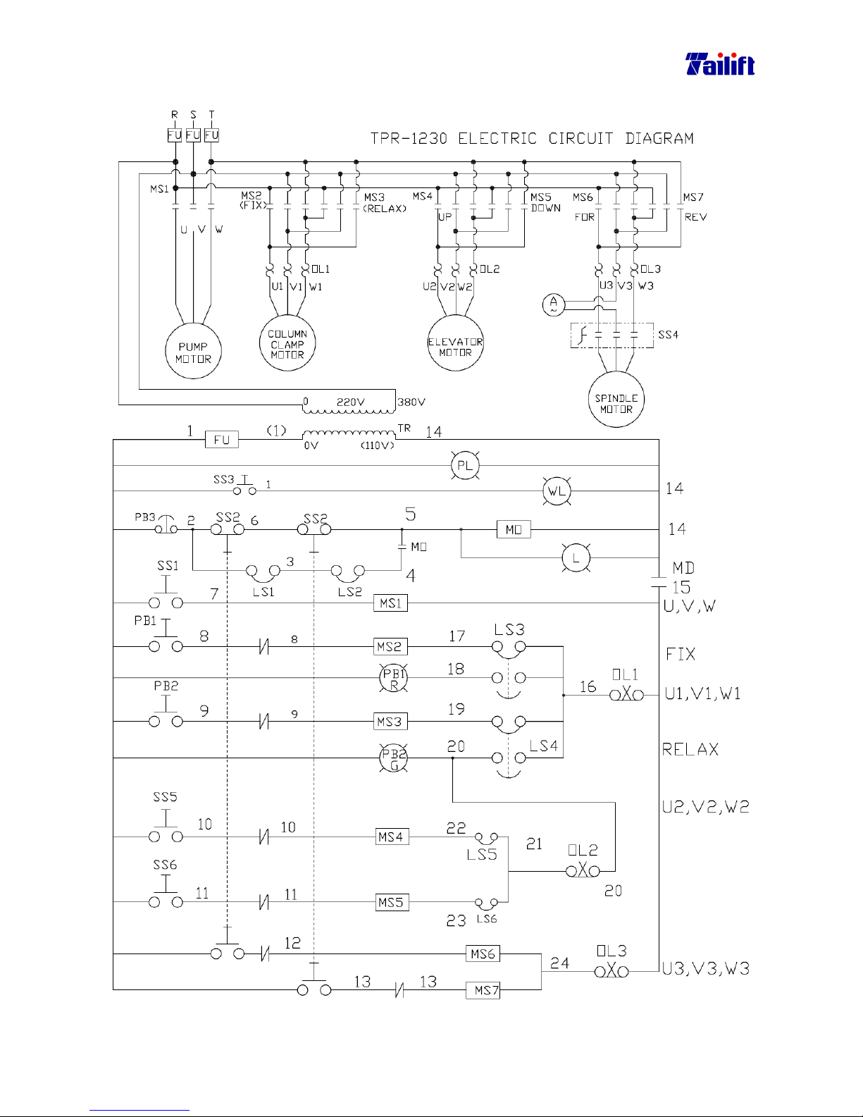
9-13
9.9 Electrical circuit diagram (For TPR-1230 Standard)
Page 84
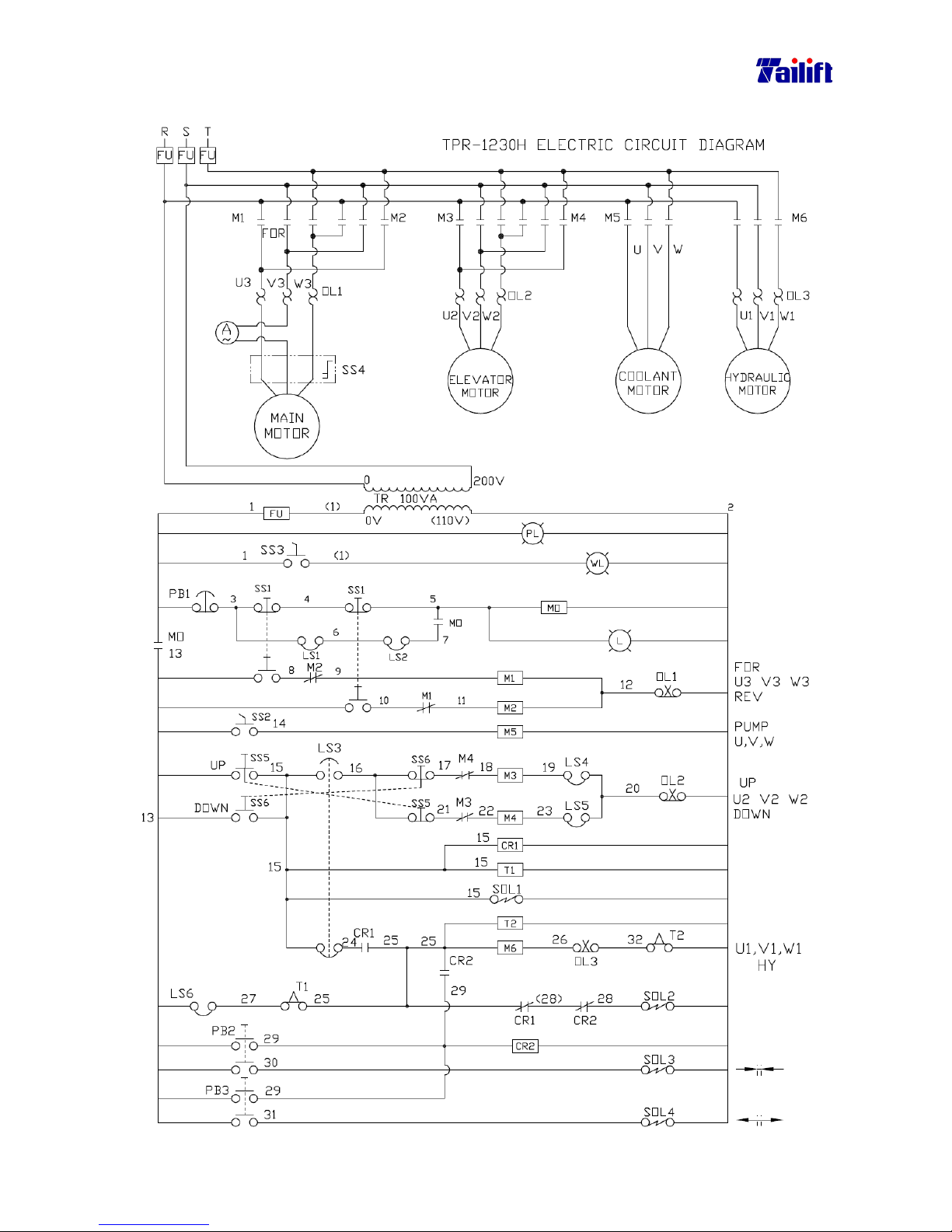
9-14
9.10 Electrical circuit diagram (For TPR-1230H Standard)
Page 85
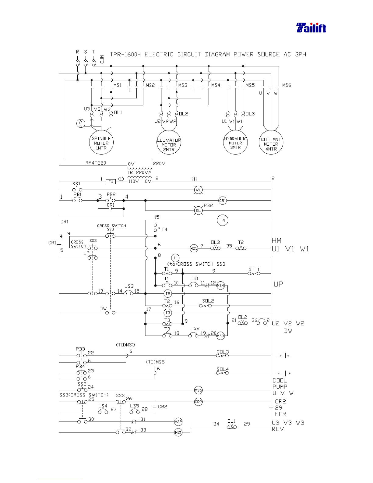
9-15
9.11 Electrical circuit diagram (For TPR-1600H, TPR-2000H S tandard)
Page 86
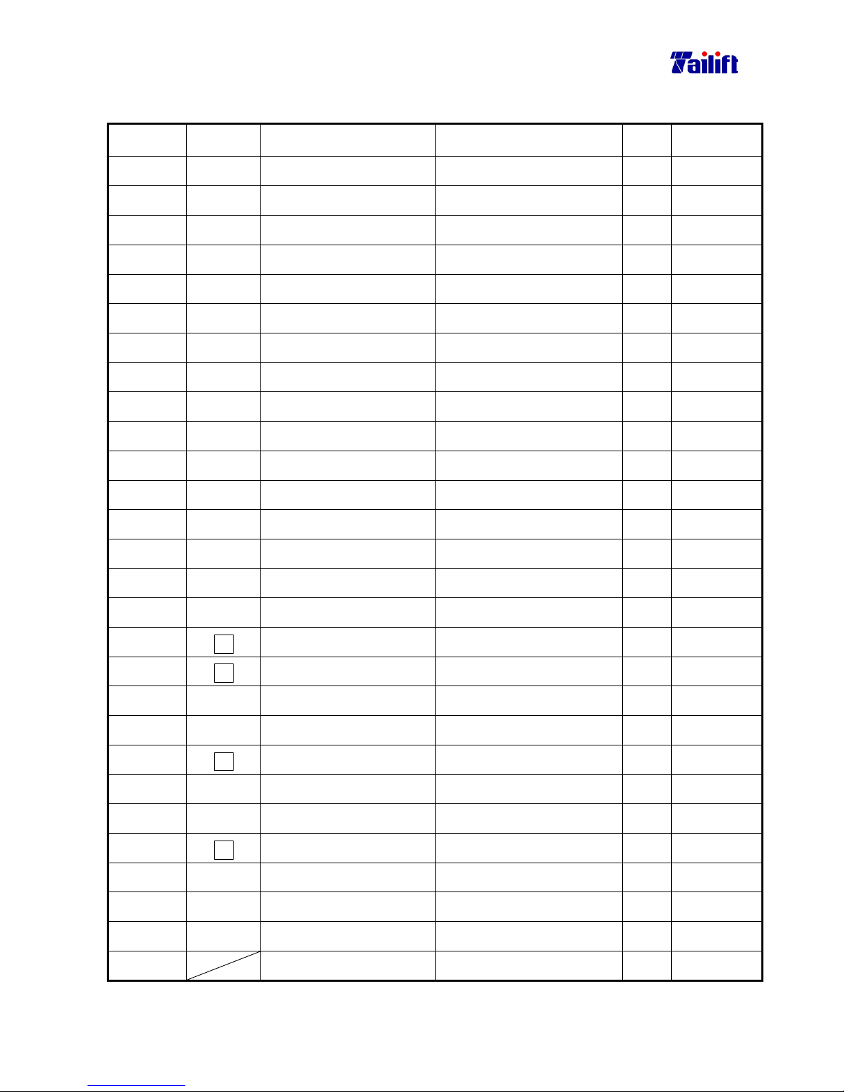
9-16
9.12 Electrical main parts list (for TPR-1230 St andard)
Part No. Symbol Description Specification Q’Ty Remarks
E0701020
MS1 Magnetic Contactor CU11,3a1b,110V
1
Standard
E0701020
MS2 Magnetic Contactor CU11,3a1b,110V
1 Standard
E0701020
MS3 Magnetic Contactor CU11,3a1b,110V
1 Standard
E0701020
MS4 Magnetic Contactor CU11,3a1b,110V
1 Standard
E0701020
MS5 Magnetic Contactor CU11,3a1b,110V
1 Standard
E0701021
MS6 Magnetic Contactor CU18,110V
1 Standard
E0701021
MS7 Magnetic Contactor CU18,110V
1 Standard
E0701020
MO Magnetic Contactor CU11,3a1b,110V
1 Standard
E0703004
MS1 Magnetic Contactor CU11,3a1b,24V
1 Optional
E0703004
MS2 Magnetic Contactor CU11,3a1b,24V
1 Optional
E0703004
MS3 Magnetic Contactor CU11,3a1b,24V
1 Optional
E0703004
MS4 Magnetic Contactor CU11,3a1b,24V
1 Optional
E0703004
MS5 Magnetic Contactor CU11,3a1b,24V
1 Optional
E0703005
MS6 Magnetic Contactor CU18,24V
1 Optional
E0703005
MS7 Magnetic Contactor CU18,24V
1 Optional
E0703004
MO Magnetic Contactor CU11,3a1b,24V
1 Optional
E2802003
Fu
Fuse Seat 3P(14*51)
1 For U.S.A
E2802013
Fu
Fuse Seat 1P(14*51)
1 For U.S.A
E3101012
Fu
Fuse 40A(14*51)
1 For U.S.A
E3101016
Fu
Fuse 5A(14*51)
1 For U.S.A
E3101009
Fu
Fuse Seat E-16
1 For Asia
E3101010
Fu
Fuse E16 30A
1 For Asia
E3101013
Fu
Fuse E16 6A
1 For Asia
E3101019
Fu
Fuse Seat 10*38
1 For Europe
E3101027
Fu
Fuse 10*38*20A
1 For Europe
E3101024
Fu
Fuse 10*38*4A
1 For Europe
E1801005
TR Transformer PT40
1 Standard
E1602001
Safety Switch XF163B 1
Optional
Page 87

9-17
Part No. Symbol Description Specification Q’Ty Remarks
E1303001
SS1 Selector Switch ST-302 1
Standard
E1605001
SS2 Cross Switch
3Joint (L)1a1b (R)1a1b UP 1a Down 1a
1
Optional
E0901021
SS2 Limit Switch
V-15-1E5
4
Standard
E1605001
SS2 Cross Switch
Up 1A Down 1A
LEFT 1A1B RIGHT 1A1B
1
Optional
E1604001
SS3 Selector Switch
SN 1021
1
Standard
E1603001
SS4
Switch for Change Speed
A441,CA10
1
Standard
B100006
SS5 Push Button
ZB4-BA2+ ZB4-BZ101
1
Standard
B100006
SS6 Push Button
ZB4-BA2+ ZB4-BZ101
1
Standard
E1701002
WL Work Lamp
FS 51441
1
Standard
E1202011
PB1 Photo Buckle
YKφ22,110V,1a1b (R)
1
Standard
E1202003
PB2 Photo Buckle
YKφ22,110V,1a1b (G)
1
Standard
E1618001
E1618003
PB3
Emg Pash Button Switch
SBT-307 or YK30Φ1B
1
Standard
E1202002
PB1 Photo Buckle
YKΦ22 24V 1a1b (Red)
1
Optional
E1202001
PB2 Photo Buckle
YKΦ22 24V 1a1b (Green)
1
Optional
E2303003
PL Pilot Light
SP301 110V (Red)
1
Standard
E2305003
PL Pilot Light
YK30Φ 24V (Red)
1
Optional
E2305001
L Control Light
YKΦ30 24V(White)
1
Optional
E2303004
L Control Light
SP301 110V (White)
1
Standard
E0207016
OL1
Overload Relay
RHN 10/3.5~5
1
For 200~230V
E0207016
OL2
Overload Relay
RHN 10/3.5~5
1
For 200~230V
E0207036
OL3
Overload Relay
RHN 10/12.5~18
1
For 200~230V
E0207018
OL1 Overload Relay
RHN 10/1.8~2.7
1
For 380~460V
E0207018
OL2 Overload Relay
RHN 10/1.8~2.7
1
For 380~460V
E0207017
OL3 Overload Relay
RHN10/5.5~8.5
1
For 380~460V
E0901006
LS1 Micro Switch
MJ2-1308R
1
Standard
E0901008
LS2 Micro Switch
TZ-8104
1
Standard
E0901007
LS3 Micro Switch
MJ2-1704
1
Standard
E0901007
LS4 Micro Switch
MJ2-1704
1
Standard
Page 88
9-18
Part No. Symbol Description Specification Q’Ty Remarks
E0901007
LS5 Micro Switch
MJ2-1704
1
Standard
E0901007
LS6 Micro Switch
MJ2-1704
1
Standard
E3602001
Amp Meter
SO65,30A
1
Standard
Coolant Pump Motor
1/8HP 2P 3HP L:130mm
Column Clamping Motor
Vertical 1HP,4P,3PH
Elevating Motor
Horizontal 1HP,4P,3PH
Main Motor
Vertical 3HP/1.5HP
Page 89
9-19
9.13 Electrical main parts list (for TPR-1230H Standard)
Part No. Symbol Description Specification Q’Ty Remarks
E0701021
M1
Magnetic
CU18 110V
1
Standard
E0701021
M2
Magnetic
CU18 110V
1
Standard
E0701020
M3
Magnetic
CU11,3a1b,110V
1
Standard
E0701020
M4
Magnetic
CU11,3a1b,110V
1
Standard
E0701020
M5
Magnetic
CU11,3a1b,110V
1
Standard
E0701020
M6
Magnetic
CU11,3a1b,110V
1
Standard
E0701020
M0
Magnetic
CU11,3a1b,110V
1
Standard
E0703005
M1
Magnetic
CU18 24V
1
Optional
E0703005
M2
Magnetic
CU18 24V
1
Optional
E0703004
M3
Magnetic
CU11,3a1b,24V
1
Optional
E0703004
M4
Magnetic
CU11,3a1b,24V
1
Optional
E0703004
M5
Magnetic
CU11,3a1b,24V
1
Optional
E0703004
M6
Magnetic
CU11,3a1b,24V
1
Optional
E0703004
M0
Magnetic
CU11,3a1b,24V
1
Optional
E0211002
CR1 Control Relay MK3P 110V
1
Standard
E0211002
CR2 Control Relay MK3P 110V
1
Standard
E0211012
CR1 Control Relay MK3P 24V
1
Optional
E0211012
CR2 Control Relay MK3P 24V
1
Optional
E2802003
Fu
Fuse Seat 3P(14*51)
1
For U.S.A
E2802013
Fu
Fuse Seat 1P(14*51)
1
For U.S.A
E3101012
Fu Fuse 40A(14*51)
1
For U.S.A
E3101016
Fu Fuse 5A(14*51)
1
For U.S.A
E3101009
Fu
Fuse Seat E-16
1
For Asia
E3101010
Fu Fuse E16 30A
1
For Asia
E3101013
Fu Fuse E16 6A
1
For Asia
E3101019
Fu
Fuse Seat 10*38
4
For Europe
E3101027
Fu Fuse 10*38*20A
3
For Europe
E3101024
Fu Fuse 10*38*4A
1
For Europe
Page 90

9-20
Part No. Symbol Description Specification Q’Ty Remarks
E1801005
TR Transformer PT40
1
Standard
E1602001
Safety Switch XF 163B 1
Optional
E0901021
SS1 Limit Switch
V-15-1E5
4
Standard
E1303001
SS2 Selector Switch ST-302 1
Standard
E1604001
SS3 Selector Switch SN 1021 1
Standard
E1603001
SS4
Switch for Change
Speed
A441 CA10 1
Standard
B100006
SS5 Push Button ZB4-BA2
ZB4-BZ101
ZBE-102
1
Standard
B100006
SS6 Push Button ZB4-BA2
ZB4-BZ101
ZBE-102
1
Standard
E1701002
WL Work Lamp FS 51441 1
Standard
E2303003
PL Pilot Light SP301 110V (Red) 1
Standard
E2305003
PL Pilot Light
YK30Φ 24V (Red)
1
Optional
E2303004
L Control Light SP301 110V (White) 1
Standard
E2305001
L Control Light
YK30Φ 24V (White)
1
Optional
E1618001
E1618003
PB1
Emg Push Button
Switch
SBT-307 or YK 30Φ1B
1
Standard
E1202004
PB2
Push Button
Switch
YK22Φ2A (Red)
1
Standard
E1202005
PB3
Push Button
Switch
YK22Φ2A (Green)
1
Standard
E0901006
LS1 Micro Switch MJ2-1308R 1
Standard
E0901008
LS2 Micro Switch TZ-8104 1
Standard
E0901034
LS3 Micro Switch MN-5311 1
Standard
E0901011
LS4 Micro Switch AZ 7121 1
Standard
E0901010
LS5 Micro Switch WLD2 1
Standard
E0901034
LS6 Micro Switch MN-5311 1
Standard
E0207036
OL1 Overload Relay RHN 10/12.5~18 1
For 200~230V
E0207016
OL2 Overload Relay RHN 10/3.5~5 1
For 200~230V
Page 91
9-21
Part No. Symbol Description Specification Q’Ty Remarks
E0207016
OL3 Overload Relay RHN 10/3.5~5 1
For 200~230V
E0207017
OL1 Overload Relay RHN 10/5.5~8.5 1
For 380~460V
E0207018
OL2 Overload Relay RHN 10/1.8~2.7 1
For 380~460V
E0207014
E0207008
OL3 Overload Relay RHN 10/1.4~2.1 or RH18/1.7 1
For 380~460V
E0208004
T1 Timer Relay ASTP-N6S 110V 1
Standard
E0208004
T2 Timer Relay ASTP-N6S 110V 1
Standard
E0208001
T1 Timer Relay ASTP-N6S 24V 1
Optional
E0208001
T2 Timer Relay ASTP-N6S 24V 1
Optional
E3602001
Amp Meter S065 30A 1
Standard
M0302018
SOL1¸SOL2
Solenoid Valve DSG-3 C2-02 110V 1
Standard
M0302018
SOL3¸SOL4
Solenoid Valve DSG-3 C2-02 110V 1
Standard
M0302019
SOL1¸SOL2
Solenoid Valve DSG-3 C2-02 24V 1
Optional
M0302019
SOL3¸SOL4
Solenoid Valve DSG-3 C2-02 24V 1
Optional
Coolant Pump Motor
1/8HP 2P 3PH L:130mm 1
Elevating Motor Horizontal 1HP 4P 3PH 1
Main Motor 3HP/1.5HP 4P/8P 3PH 1
Hydraulic Motor Horizontal 1HP 4P 3PH 1
A
Page 92
9-22
9.14 Electrical main parts list (for TPR-1600H Standard)
Part No. Symbol Description Specification Q’Ty Remarks
E0701022
MS1
Magnetic Contactor
CU27,110V
1
Standard
E0701022
MS2
Magnetic Contactor
CU27,110V
1
Standard
E0701020
MS3
Magnetic Contactor
CU11,3a1b,110V
1
Standard
E0701020
MS4
Magnetic Contactor
CU11,3a1b,110V
1
Standard
E0701020
MS5
Magnetic Contactor
CU11,3a1b,110V
1
Standard
E0701020
MS6
Magnetic Contactor
CU11,3a1b,110V
1
Standard
E0701020
CR1
Magnetic Contactor
CU11,3a1b,110V
1
Standard
E0701020
CR2
Magnetic Contactor
CU11,3a1b,110V
1
Standard
E0208004
T1 Timer Relay
ASTP-N,6S,110V
1
Standard
E0208005
T2 Timer Relay
AH3-2,6S,110V
1
Standard
E0208004
T3 Timer Relay
ASTP-N,6S,110V
1
Standard
E0703006
MS1
Magnetic Contactor
CU27,24V
1
Optional
E0703006
MS2
Magnetic Contactor
CU27,24V
1
Optional
E0703004
MS3
Magnetic Contactor
CU11,3a1b,24V
1
Optional
E0703004
MS4
Magnetic Contactor
CU11,3a1b,24V
1
Optional
E0703004
MS5
Magnetic Contactor
CU11,3a1b,24V
1
Optional
E0703004
MS6
Magnetic Contactor
CU11,3a1b,24V
1
Optional
E0703004
CR1
Magnetic Contactor
CU11,3a1b,24V
1
Optional
E0703004
CR2
Magnetic Contactor
CU11,3a1b,24V
1
Optional
E0208001
T1 Timer Relay
ASTP-N,6S,24V
1
Optional
E0208002
T2 Timer Relay
AH3-2,6S,24V
1
Optional
E0208001
T3 Timer Relay
ASTP-N,6S,24V
1
Optional
E0403003
NFB Circuit breaker
3P,30A,220Vor3P,20A,440V
1
Standard
E1602002
Safty Switch XF323B 1
Optional
Main Motor Vertical 7.5HP/4P/3PH 1
Standard
Elveating Motor Horizontal 2HP/4P/3PH 1
Standard
Hydraulic Motor Horizontal 1HP/4P/3PH 1
Standard
Page 93
9-23
Part No. Symbol Description Specification Q’Ty Remarks
E0208004
T4 Timer Relay ASTP-N,6S,110V 1
Standard
E0208001
T4 Timer Relay ASTP-N,6S,24V 1
Optional
M0302018
SOL1,SOL2
Solenoid Valve DSG-3C2-02 110V 1
Standard
M0302018
SOL3,SOL4
Solenoid Valve DSG-3C2-02 110V 1
Standard
M0302019
SOL1,SOL2
Solenoid Valve DSG-02-3C2 24V 1
Optional
M0302019
SOL3,SOL4
Solenoid Valve DSG-02-3C2 24V 1
Optional
E1801029
TR Transformer
250VA (1:0,220,380,415,440V
2:0,24,110V)
1
E3101019
Fu
Fuse Seat
10*38
1
E3101025
Fu Fuse
10*38,6A
1
E0207035
OL1 Overload Relay RHN-10/8.5~12.5 1
For 380V~460V
E0207037
OL1 Overload Relay RHN80/17~25AP 1
For 200V~230V
E0207017
OL2 Overload Relay RHN-10/5.5~8.5 1
For 200V~230V
E0207016
OL2 Overload Relay RHN-10/3.5~5 1
For 380V~460V
E0207016
OL3 Overload Relay RHN-10/3.5~5 1
For 200V~230V
E0207018
OL3 Overload Relay RHN-10/1.8~2.7 1
For 380V~460V
E1604001
SS1 Selector Switch SN1021 1
Standard
E1303001
SS2 Selector Switch ST302 1
Standard
E1605002
SS3 Cross Switch
5Joint, UP 2a1b, Down 2a1b
(L)1a1b, (R)1a1b
1
Standard
E1701002
WL Work Lmap FS51441 1
Standard
E1618001
E1618003
PB1
Emg Push Button
Switch
SBT-307 or YK30Φ1B 1
Standard
E1203003
PB2
Photo Buckle
YK30Φ,110V (Green)
1
Standard
E1202013
PB2
Photo Buckle
YK30Φ,24V (Green)
1
Optional
E0901013
LS1 Micro Switch WLD 1
Standard
E0901010
LS2 Micro Switch WLD2 1
Standard
E0901010
LS3 Micro Switch WLD2 1
Standard
E0901008
LS4 Micro Switch TZ-8104 1
Standard
E0901008
LS5 Micro Switch TZ-8104 1
Standard
Page 94

9-24
Part No. Symbol Description Specification Q’Ty Remarks
E1202004
PB3 Push Button
YK22Φ,2A (Red)
1
Standard
E1202005
PB4 Push Button
YK22Φ,2A (Green)
1
Standard
E3602004
Amp Meter S065(50A) 1
Standard
E0303002
Terminal block 20P 20A 1
E0303004
Terminal block TS015 28P 1
E0303001
Terminal block
12P*20A
1
E0303003
Terminal block
3P*30A
1
E0901010
LS6 Micro Switch WLD2 1
A
Page 95
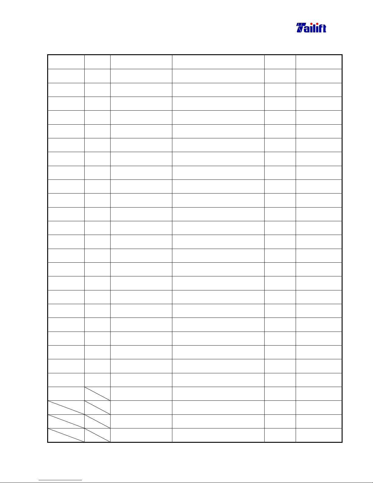
9-25
9.15 Electrical main parts list (for TPR-2000H Standard)
Part No.
Symbo
Description Specification Q’Ty Remarks
E0701022
MS1
Magnetic Contactor
CU27,110V
1
Standard
E0701022
MS2
Magnetic Contactor
CU27,110V
1
Standard
E0701020
MS3
Magnetic Contactor
CU11,3a1b,110V
1
Standard
E0701020
MS4
Magnetic Contactor
CU11,3a1b,110V
1
Standard
E0701020
MS5
Magnetic Contactor
CU11,3a1b,110V
1
Standard
E0701020
MS6
Magnetic Contactor
CU11,3a1b,110V
1
Standard
E0701020
CR1
Magnetic Contactor
CU11,3a1b,110V
1
Standard
E0701020
CR2
Magnetic Contactor
CU11,3a1b,110V
1
Standard
E0208004
T1 Timer Relay
ASTP-N,6S,110V
1
Standard
E0208005
T2 Timer Relay
AH3-2,6S,110V
1
Standard
E0208004
T3 Timer Relay
ASTP-N,6S,110V
1
Standard
E0703006
MS1
Magnetic Contactor
CU27,24V
1
Optional
E0703006
MS2
Magnetic Contactor
CU27,24V
1
Optional
E0703004
MS3
Magnetic Contactor
CU11,3a1b,24V
1
Optional
E0703004
MS4
Magnetic Contactor
CU11,3a1b,24V
1
Optional
E0703004
MS5
Magnetic Contactor
CU11,3a1b,24V
1
Optional
E0703004
MS6
Magnetic Contactor
CU11,3a1b,24V
1
Optional
E0703004
CR1
Magnetic Contactor
CU11,3a1b,24V
1
Optional
E0703004
CR2
Magnetic Contactor
CU11,3a1b,24V
1
Optional
E0208001
T1 Timer Relay
ASTP-N,6S,24V
1
Optional
E0208002
T2 Timer Relay
AH3-2,6S,24V
1
Optional
E0208001
T3 Timer Relay
ASTP-N,6S,24V
1
Optional
E0403003
NFB Circuit breaker
3P,30A,220Vor3P,20A,440V
1
Standard
E1602002
Safty Switch XF323B 1
Optional
Main Motor Vertical 7.5HP/4P/3PH 1
Standard
Elveating Motor Horizontal 3HP/4P/3PH 1
Standard
Hydraulic Motor Horizontal 1HP/4P/3PH 1
Standard
Page 96
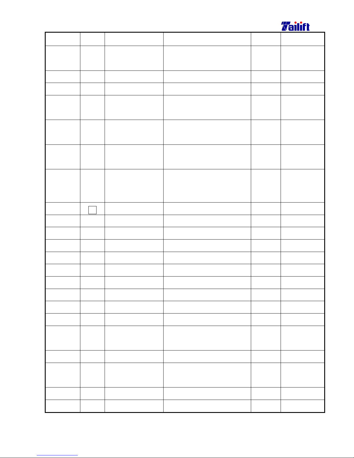
9-26
Part No.
Symbo
Description Specification Q’Ty Remarks
M0302018
SOL1
SOL2
Solenoid Valve DSG-3C2-02 110V 1
Standard
E0208004
T4 Timer Relay ASTP-N,6S,110V 1
Standard
E0208001
T4 Timer Relay ASTPN,6S,24V 1
Optional
M0302018
SOL3
SOL4
Solenoid Valve DSG-3C2-02 110V 1
Standard
M0302019
SOL1
SOL2
Solenoid Valve DSG-02-3C2 24V 1
Optional
M0302019
SOL3
SOL4
Solenoid Valve DSG-02-3C2 24V 1
Optional
E1801029
TR Transformer
250VA
(1:0,220,380,415,440V
2:0,24,110V)
1
E3101019
Fu
Fuse Seat
10*38
1
E3101025
Fu Fuse
10*38,6A
1
E0207035
OL1 Overload Relay RHN-10/8.5~12.5 1
For 380V~460V
E0207037
OL1 Overload Relay RHN-80/17~25AP 1
For 200V~230V
E0207035
OL2 Overload Relay RHN-10/8.5~12.5 1
For 200V~230V
E0207034
OL2 Overload Relay RHN-10/4~6 1
For 380V~460V
E0207016
OL3 Overload Relay RHN-10/3.5~5 1
For 200V~230V
E0207018
OL3 Overload Relay RHN-10/1.8~2.7 1
For 380V~460V
E1604001
SS1 Selector Switch SN1021 1
Standard
E1303001
SS2 Selector Switch ST302 1
Standard
E1605002
SS3 Cross Switch
5Joint, UP 2a1b, Down 2a1b
(L)1a1b, (R)1a1b
1
Standard
E1701006
WL Work Lmap FS21441 1
Standard
E1618001
E1618003
PB1
Emg Push Button Switch
SBT-307 or YK30Φ1B 1
Standard
E1203003
PB2
Photo Buckle
YK30Φ,110V (Green)
1
Standard
E1202013
PB2
Photo Buckle
YK30Φ,24V (Green)
1
Optional
Page 97
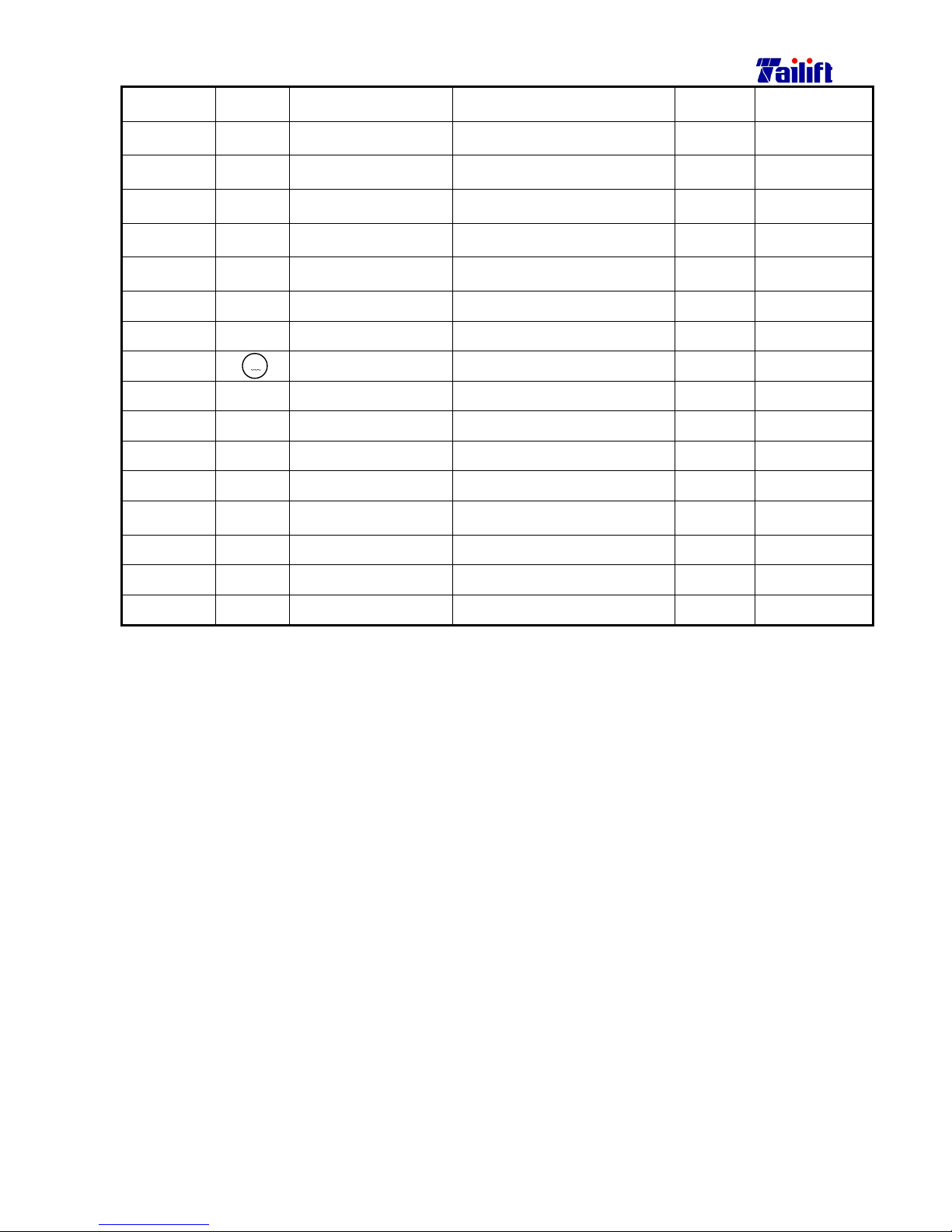
9-27
Part No. Symbol Description Specification Q’Ty Remarks
E0901013
LS1 Micro Switch WLD 1
Standard
E0901010
LS2 Micro Switch WLD2 1
Standard
E0901010
LS3 Micro Switch WLD2 1
Standard
E0901008
LS4 Micro Switch TZ-8104 1
Standard
E0901008
LS5 Micro Switch TZ-8104 1
Standard
E1202004
PB3 Push Button
YK22Φ,2A (Red)
1
Standard
E1202005
PB4 Push Button
YK22Φ,2A (Green)
1
Standard
E3602004
Amp Meter S065(50A) 1
Standard
E0303002
Terminal block 20P 20A 1
E0303004
Terminal block TS015 28P 1
E0303001
Terminal block
12P*20A
1
E0303003
Terminal block
3P*30A
1
A
Page 98
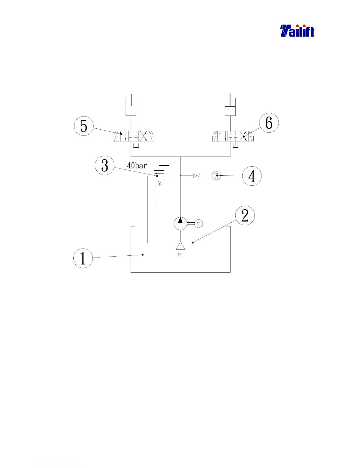
9-28
9.16
Diagram for hydraulic system (only for TPR-1230H/TPR-1600H/
TPR-2000H)
P1:The pressure set to 38 bar.
Hydraulic of unload equipment
The operated pressure requires 38bar. When the pressure system can be
maintained to 38bar. But pipe has clo
g
, furthermore hydraulic of pressure
continue to rise. To further ensure safet
y
, the unloading valve(part 3.) is
employed to unload the motion if the pressure is over the setting of 40bar.
Page 99
9-29
9.17
Hydraulic system main parts list (only for TPR-1230H/TPR-1600H/
TPR-2000H)
NO Name Specification Q’ty
1 Tank 1
2 Hydraulic Pump HGP-1A-F6R 1
3 Release Valve DG-02-L 1
4 Pressure Gauge
2
1"
2
×70bar
1
5 Solenoid Valve DSG-02-3C2 1
6 Solenoid Valve DSG-02-3C2 1
 Loading...