

Page 1

Table of Contents
■Safety Precautions…………2~3
■Applications…………………4
■Operating Concepts………4
■Parts Identification…………5
■Installation……………………6
■Setting up……………………7~8
■Operation……………………9
■Maintenance……………….10~11
■Servicing / Specifications…11
TAIJI SAKE WARMER DISPENSER
INSTRUCTION MANUAL
MODEL : TSK-160
· Before operating this product, please read this manual for instructions
and proper operation.
· This product is for heating and dispensing Sake only and intended for
indoor use only. Do not use for any other purposes.
· Keep this manual in a place where it can be reached for immediate references.
Thank you for purchasing TAIJI Sake Warmer Dispenser.
Page 2

WARNINGS:
• Contact a disposal service provider, municipal government office or your
distributor for proper disposal of this product according to enviromental regulations.
Failing to adhere to the following warnings may cause
danger to human life or inflict a severe injury.
SAFETY PRECAUTIONS
SAFETY PRECAUTIONS
-2-
■ Please peruse these “Safety Precautions” carefully so that you can use your “Sake Warmer
Dispenser” in the proper way.
■ Please keep these “Safety Precautions” handy for future reference after being read.
■ Precautionary measures referred to herein are matters which should be abided by for safe
use and to prevent harm and/or damage being inflicted on yourself or others. Furthermore,
the particulars of the precautionary measures have been classified into “Warning” and “Caution”
to express the degree or extent of conceivable harm and damage which can be assumed to
occur from mishandling. They are both of importance as far as safety is concerned and should
be strictly abided by.
What is assumed to possibly result in death or serious injury.
What is assumed to possibly result only in bodily injury or physical damage.
△ mark denotes that “Warning and caution is urged.”
(The one on the left indicates beware of electrical shock.)
mark with a diagonal line means “Forbidden.”
(The one on the left indicates disassembling forbidden.)
● indicates “Instructions” which should be followed by all means.
(The one on the left indicates grounding is a requirement.)
■ What precautionary measures should be abided by are expressed by certain marks
and explained as follows:
WARNING
CAUTION
• Install this product on a level, steady surface.
• Do not disassemble, tamper or attempt to repair this product. Contact
your distributor for servicing.
• Do not immerse this product in water or splash water on this product.
• Do not use this product outdoors. This product is for indoor use only.
• This product is to be operated by persons who understand its functions and operations.
Keep children away from this product or any other commercial appliances.
• This product should be connected to an exclusive wall outlet supplying power
of AC220-240V and 10A (minimum). Do not use an extension cord.
• Do not tamper with the plug blades.
• Avoid damaging the power cord. Do not place any object on the cord.
Do not nip or tamper with the cord. Keep the cord away from any heat sources.
Page 3

CAUTIONS:
Failing to adhere to the following cautions may result in
personal injuries or property damages.
• This appliance is not intended for use by persons (including children) with
reduced physical, sensory or mental capabilities, or lack of experience and
knowledge, unless they have been given supervision or instruction concerning
use of the appliance by a person responsible for their safety.
Children should be supervised to ensure that they do play with the appliance.
-3-
• Properly and promptly discard the packaging materials such as plastic bags.
• Do not operate this product if it has been damaged or dropped.
• Do not operate this product if the power cord or plug is damaged.
• Make sure your hands are dry when plugging/unplugging the power plug or
turning on/off the power switch.
• Do not pull the plug pulling by the cord. Pull the plug from the base of it
when inserting into or removing from the outlet.
• When not in use, remove the plug from the outlet.
• Do not use this product for other than heating Sake (Japanese rice wine).
• Avoid contacting with the Sake heating unit as it gets hot during operation.
• Be very careful when pouring heated Sake into a Sake server bottle.
Page 4

This product is intended for heating Sake only.
The product should not be used outdoors.
This product is an electric Sake heater.
• Sake is fed into the stainless steel heat exchange pipe.
• The stainless steel pipe runs through the water.
• The water bath is heated by the heater.
• The water temperature is monitored by the temperature sensor and
controlled by the temperature control device.
OPERATING CONCEPTS
OPERATING CONCEPTS
APPLICATIONS
APPLICATIONS
Temperature Sensor
Water Tank
Heat Exchange Pipe
Cubic Container
Sake Bottle
Air Vent
Stopcock
Heat Exchange Pipe
Float Switch
Heater
Solenoid Valve
Solenoid Valve
Water Tank Inlet
Water Tank
Float Switch
Temperature Sensor
Heater
Nozzle
Water Tank Overflow Outlet
Water Tank Overflow Outlet
Nozzle
Water Tank Inlet
Air Vent
-4-
Page 5
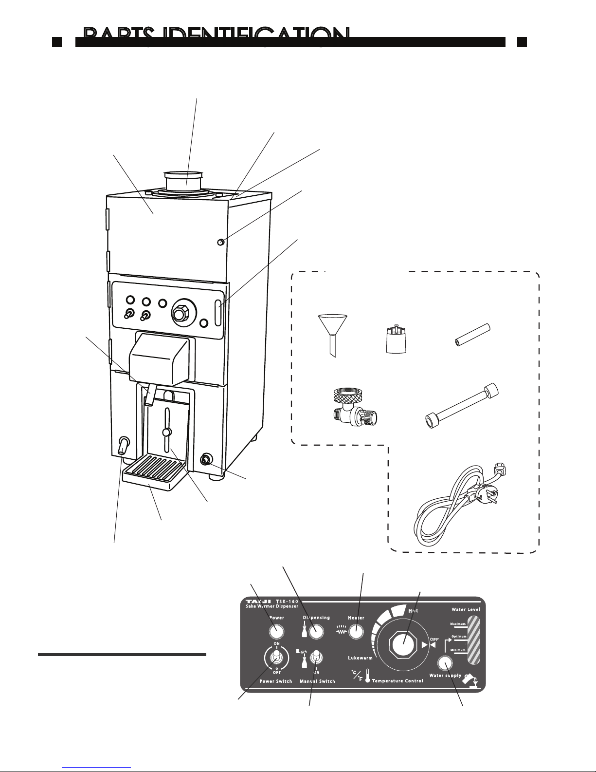
Nozzle
Water Tank Overflow Outlet
Server Bottle Holder
Control Panel
Tray
Overflow Outlet
Water Level Indicator
Accessories
Bottle Holder Funnel / Bottle Holder (Filter inside)
Water Tank Inlet
Air Vent
Urea Resin Screw
Door
Temperature Control Knob
Heater Lamp
Dispensing Lamp
Power Lamp
Power Switch
Manual Switch
Water Supply Lamp
Po w er
Sa ke Wa rm er D is pe ns er
T S K - 1 6 0
Lu k e wa r m
I
ON
M an u al Sw i t chPo w er S wi t ch
D is p en s in g
H ea t er
Te m pe r at u r e C on t ro l
Wa t er s up p ly
Wa t er Le v e l
OF F
ON
I
O
OF F
H ot
Op t im u m
Ma x im u m
Mi n im u m
Funnel
Silicone Tubing
Cap
Stopcock
Joint Hose
Detachable Power Cord
PARTS IDENTIFICATION
PARTS IDENTIFICATION
-5-
Page 6
1. Take the unit out of the shipping carton and remove all packaging materials.
Check that all parts and accessories are included with the unit.
2. For installing, the location must have/be:
• A level and steady surface
• Sufficient space for air circulation around the unit
• Be at least 50 cm away from any heat source
• No direct sunlight
• Avoid high-humidity areas and areas near water
• Use the equipment splash condition as per “IPx5” as the minimum guideline.
3. Initial uses:
Before operating this product for the first time, clean the interior of the
main unit by following the instructions in the “Maintenance/Daily Cleaning”
section of this manual.
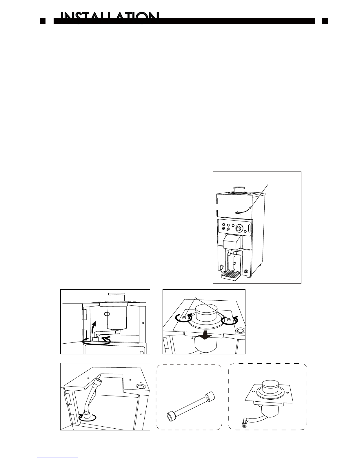
4. How to change Sake feeder; Bottle Type to Cubic Container Type:
For using Cubic container type, set up the
machine as follows.
-6-
INSTALLATION
INSTALLATION
1) Loosen the Urea resin screw
and open the door. (Fig.1)
2) Remove a joint between the main unit
and Bottle holder. (Fig.2)
3) Remove two Urea resin screws and remove
the Bottle holder unit. (Fig.3)
4) Screw the Joint hose (accessory) into
the main unit.(Fig.4)
(Fig.1)
Urea Resin Screw
(Fig.2)
(Fig.3)
(Fig.4)
Joint Hose
Bottle Holder Unit
Urea Resin Screws
Page 7
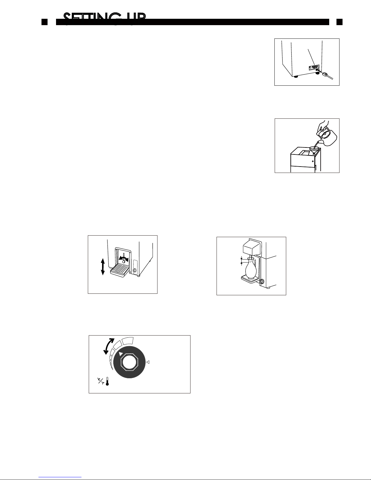
1. Insert the Power supply cord into the inlet. (Fig.5)
2. Connect the power cord to an exclusive wall outlet with an
AC220V-240V and 10A (minimum) power source.
Do not use an extension cord.
3. Make sure the Water tank overflow outlet is closed.
4. Make sure the water level in the Water Tank is at the “optimum” level.
To add water:
・Slowly add water using the accessory funnel. (Fig.6)
・Always fill water until the “Optimum” level on the water
level indicator.
・The Water tank holds approximately 4.7 liter of water.
・Excessive water (beyond the maximum level) will be discharged
through the overflow outlet.
5. Adjust the height of the Sake server bottle holder according to the size
of your Sake serving bottles. (Fig.7 & 8)
(Fig.8)
2 cm
6. Turn the power switch on. Set the Sake temperature to your favorite temperature
by turning the temperature control knob. (Fig.9)
-7-
(Fig.6)
Lu k e wa r m
Te m pe r at u r e C on t ro l
OF F
H ot
(Fig.9)
SETTING UP
SETTING UP
(Fig.7)
(Fig.5)
Inlet
7. Set Sake (1.8-liter Sake bottle or Cubic container) to the dispenser.
Page 8
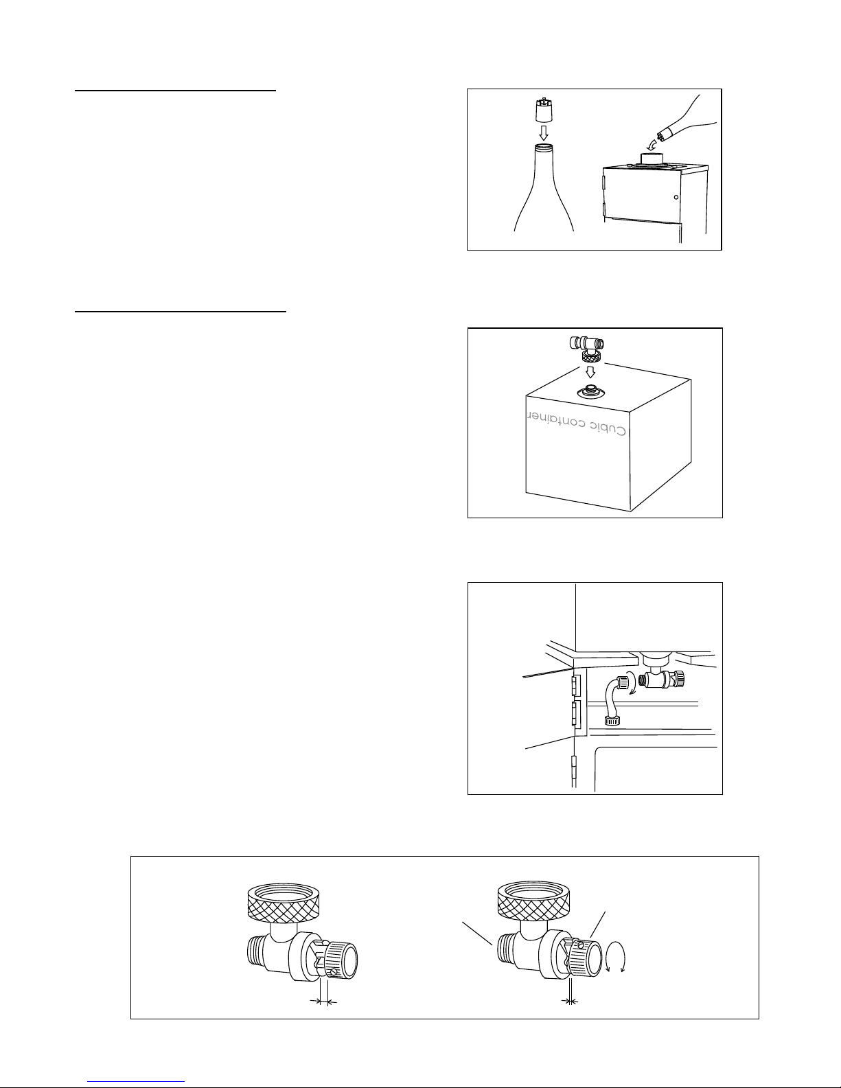
1) Remove a cap of the Cubic container.
2) Check the knob of the Stopcock is set at
the closed position. (Fig. 13)
Then, screw it into the mouth of the
container. Be sure the outlet of the
Stopcock facing to the right. (Fig. 11)
*Sake will leak out if this screw-in process
proceeds improperly.
3) Place the cubic container on the top
of the unit and position the mouth of
the container downward.
The Sake outlet of the Stopcock should
face to the left. (Fig. 12)
4) Screw the Joint hose into the outlet
of the Stopcock. This joint connects
Cubic container and the dispenser
main body. (Fig. 12)
5) Before dispensing, make sure the
Stopcock and Joint hose are firmly
fastened. Also, check the Nozzle has
been pulled up.
6) Turn the knob of the Stopcock to
the right and adjust it to the
“Open position”. (Fig.13)
1) Put the accessory cap to a Sake bottle.
(Fig.10)
2) Make sure the Nozzle has been pulled up.
3) Insert the Sake bottle in the Bottle
holder funnel. (Fig. 10)
(Fig.10)
Bottle Type
Cubic container Type
(Fig.13)
Wide gap
“Open position” “Close position”
Narrow gap
Knob
Sake outlet
Open - Close - Open
- Close - ......
Cubic container
(Fig.12)
(Fig.11)
-8-
Page 9
OPERATION
OPERATION
1. Wait until the Heater lamp goes off.
After turning on the unit, the Heater lamp will be lit.
The Sake is at the set temperature when the lamp is off.
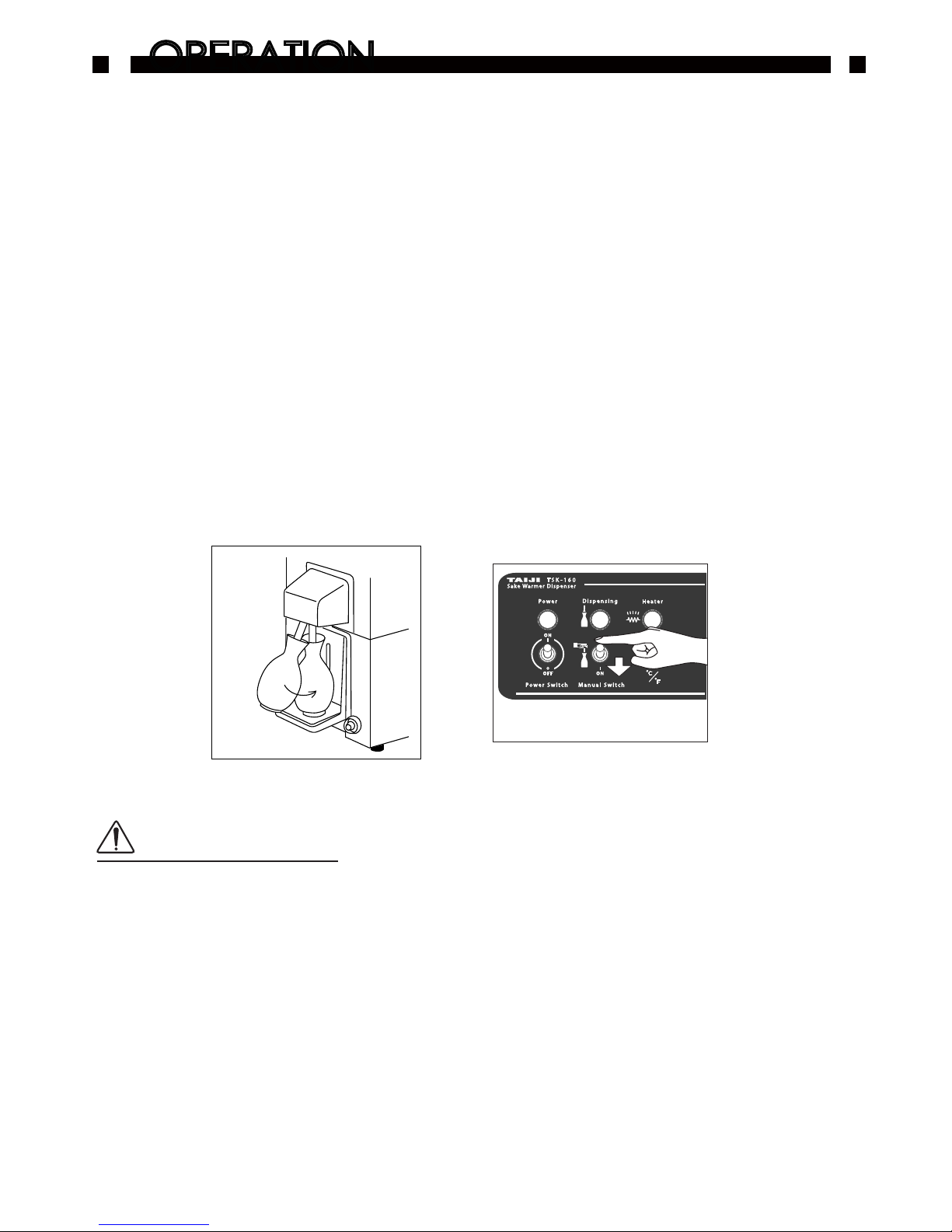
2. Fit the Nozzle (Sake outlet) into the mouth of the Sake server bottle
into hte Nozzle (Sake outlet).
Lightly push the bottle until the Nozzle is staight down, and place it onto the
Server bottle holder. (Fig.14)
3. The Dispensing lamp will be turned on - the
warmed Sake begins to come out.
5. When the Sake in the server bottle touches the tip of the Nozzle,
the Dispensing lamp will be turned off.
*If you want to dispense more Sake, pull down the Manual switch. (Fig.15)
6. Remove the server bottle by the reverse procedure of step 2.
■ Be very careful not to burn yourself as the Sake may be quite hot
depending on the temperature setting.
■ At the beginning of each operating session, pour out a little amount
of Sake to check the temperature and to make sure that it does not
contain any impurities such as water left behind from cleaning.
■ Dispensing a large amount of Sake at one time or operating in a cold
environment may lower the temperature of Sake being dispensed.
Adjust the temperature setting to compensate for the effects of
such circumstances.
(Fig.14)
-9-
Po w er
Sa ke Wa rm er D isp en se r
T S K - 1 6 0
I
ON
Ma n u al Sw i tc hPo w er Sw i tc h
Di s p en s in g
He a te r
ON
I
O
OF F
(Fig.15)
Cautions:
Page 10
-10-
MAINTENANCE
MAINTENANCE
Daily Cleaning
Bottle Type
1. Pull out the Sake bottle and drain the Sake left in the dispenser.
Discard the Sake or you may use it for coocking.
To drain Sake, pull the Manual switch and wait until the Sake stops coming out.
2. Remove the Sake server bottle holder. Place an empty container under the Nozzle
of the dispenser.
3. Remove the Bottle holder funnel. Feed hot water (below 70oC) to the bottle holder.
4. Pull the Nozzle down or pull the Manual switch down.
*Do not use any detergent.
Hot water comes out of the Nozzle and the inside of the pipes are cleaned.
Repeat the step No. 2~4 three times or so.
5. Turn off the Power switch.
6. Pull out the power plug from the outlet.
Cubic container Type
1. Close the Stopcock of the cubic container.
2. Dispense all Sake left inside the dispenser.
Discard the Sake or you may use it for cooking.
3. Remove the cubic container from the top of the dispenser.
4. Set the Bottle holder unit. (Ref. P6 No.4)
5. Go to the section of Daily Cleaning, Bottle Type, No.2-6
External Components
Wash the following external components with hot water.
· Sake server bottle holder
· Bottle holder funel, Bottle holder, filter, Cap (Bottle Type).
At the beginning of the next operating session, dispense a small amount of Sake,
since a small amount of cleaning water may remain in the system after cleaning.
Discard or use this Sake for cooking.
CAUTIONS:
Be careful hot to scald yourself with hot water.
To prevent machine failures and accidents do not wash or clean the equipment
by water-Jet or similar method.
CAUTIONS:
Page 11
SERVICING
SERVICING
SPECIFICATIONS
SPECIFICATIONS
■ For servicing of this product, please contact your distributor, nearest TAIJI sales
representative or TAIJI & CO., LTD.
■ If the Power supply cord is damaged, it must be replaced by the manufacturer, its
service agent or similarly qualified persons in order to avoid a hazard.
TAIJI & CO., LTD.
8-2, Okawa-cho, Kawasaki-ku, Kawasaki-shi, Kanagawa-pref., 210-0858, Japan
T EL : +81-44-329-6338
FAX : +81-44-329-5860
E-mail : [email protected]
URL : http://www.taiji.co.jp/e
M od el
P ow er S u pp l y
P ow er C o ns u m p ti on
T em pe r a t ur e C on tr o l
H ea ti n g Me t h o d
S ak e f e e de r
S af et y D ev i c e
D im en s i o ns
W ei gh t
A cc es s o r ie s
T SK -1 6 0
S in gl e P ha s e 22 0- 2 4 0 V, 5 0 /6 0H z
1 37 5- 1 5 0 0W
V ar ia b l e T h e r mo st a t
I nd ir e c t h e a t in g v i a w a t e rb at h
1 .8 L S a k e b o t tl e o r 18 L C ub ic c o nt a i n er
L in e F u s e 1 0 A
W 25 0m m x D 3 7 5 mm x H 5 98 m m
W ei gh t 1 0. 4 K g
0 ゚ C t o 4 0゚ CA mb ie n t Te m p e ra tu r e
F un ne l , Ca p , S il i c o ne T u bi ng , S to p c o ck ,
Jo i n t H o s e , De t a c ha b l e P ow e r Co r d
* Sp ec i f i ca t i o ns s u b j ec t t o ch a n g e w i t ho ut n o ti ce
-11-
Main Unit
1. Body
1) Wipe with dry or tightly-wrung wet cloth.
*Never use any solvent such as thinner or benzene.
2. Nozzle
1) Clean the Nozzle one or twice, or even more, each month.
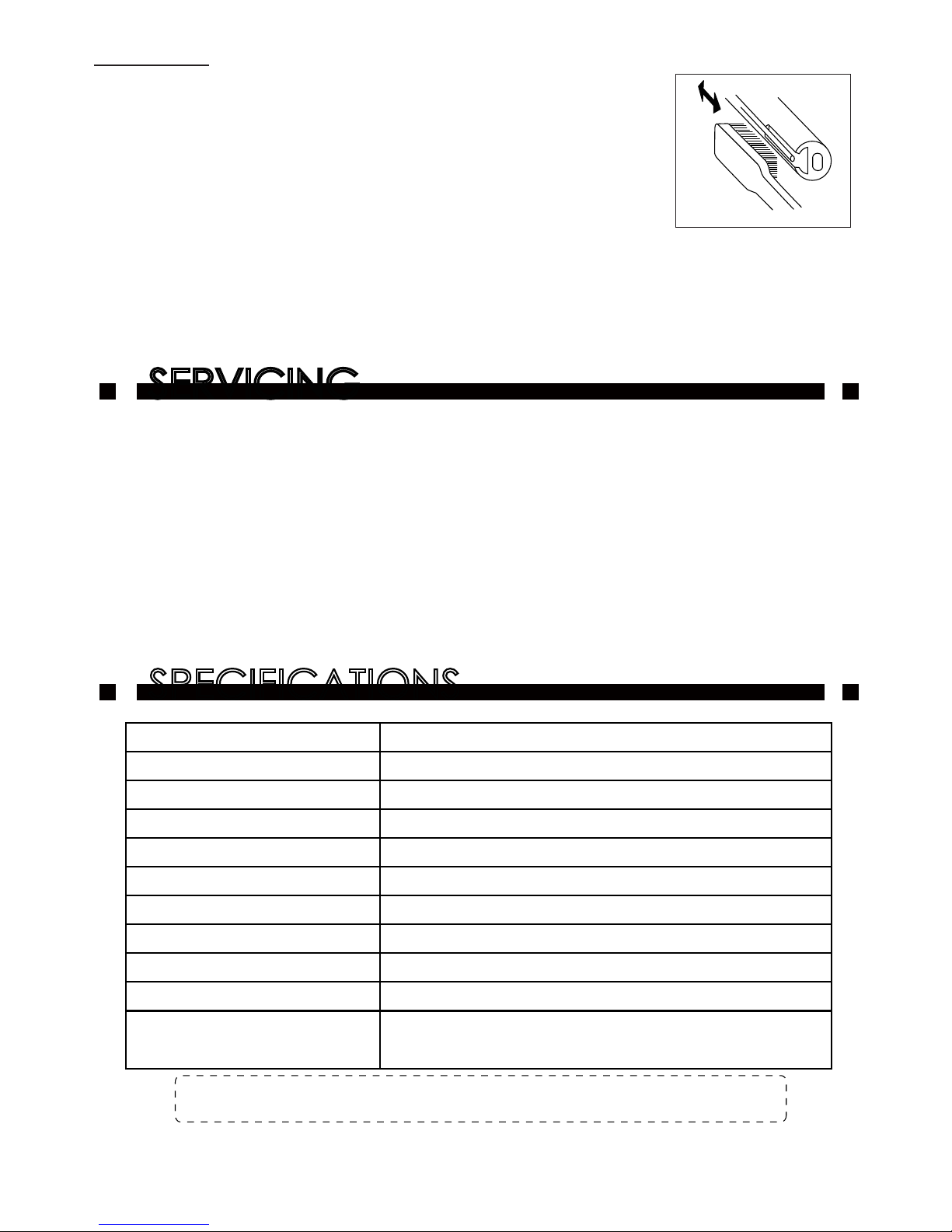
2) Gently scrub the sensor electrode on the tip of the Nozzle
with a tooth brush.(Fig. 16)
3. Water Tank
Replace the water in the Water tank at least once a month.
Make sure the water bath is completely cooled down before draining water.
1) Connect Silicone tubing to the Water tank overflow outlet .
2) Open the Water tank overflow outlet to drain water.
(Fig.16)
Silicone tubings and Sake flow part materials are complied with
Japan Food Sanitation Act.
Page 12

( 09 08 B )
h t tp : ww w .t a ij i .c o .j p /e
 Loading...