

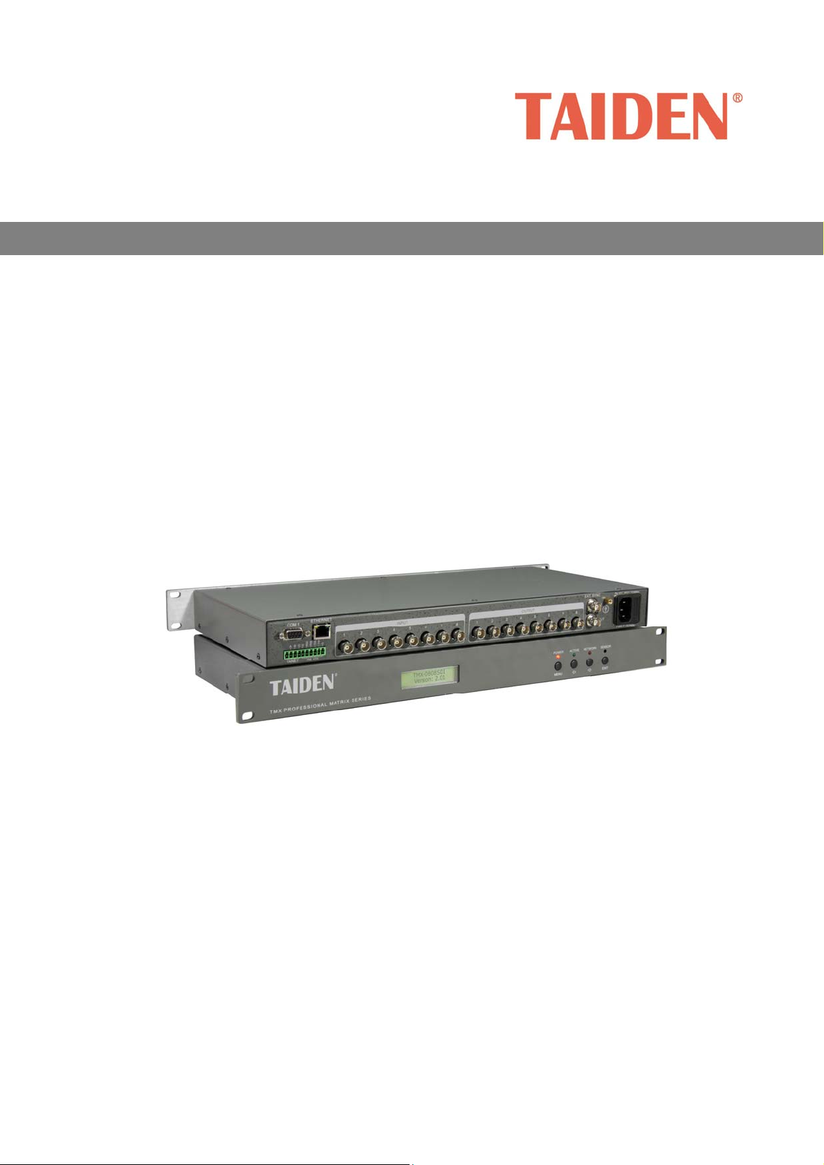
High Definition Digital Video Tracking Matrix Switcher
Professional Matrix Switchers
Installation and Operation Manual
V 1.1

Remark:
All rights reserved for translation, reprint or reproduction
Contents may change without prior announcement
All technical specifications are guideline data and not guaranteed features
Taiden Co., Ltd. is not responsible for any damage caused by improper use of this manual
The equipment must be connected to earth!
This product conforms to the rules of the European directive 2004/108/EC.
If any detailed information needed, please contact your local agent or TAIDEN service center in your region.
Any feedback, advice and suggestion about the products is appreciated
TAIDEN is the registered trademark of TAIDEN Co., Ltd.
I
Important Safety Instruction
1. Read and keep these instructions.
2. Heed all warnings and follow all instructions.
3. The apparatus shall not be exposed to dripping or
splashing and that no objects filled with liquids, such
as vases, shall be placed on the apparatus.
4. The MAINS plug serving as a disconnection device,
should be easy to operate.
5. The apparatus should be connected to the MAINS
socket-outlet with protective earth.
6. Clean only with dry cloth.
7. Do not block any ventilation openings. Install in
accordance with the manufacturer’s instructions.
8. Do not install near any heat sources such as radiators,
heat registers, stoves, or other apparatus (including
amplifiers) that produce heat.
9. Do not defeat the safety purpose of the polarized or
grounding-type plug. A polarized plug has two blades
with one wider than the other. A grounding type plug
has two blades and a third grounding prong. The wide
blade and the third prong are provided for your safety.
If the provided plug does not fit into your outlet,
consult an electrician for replacement of the obsolete
outlet.
10. Protect the power cord from being walked on or
pinched particularly at plugs, convenience
receptacles, and the point where they exit from the
apparatus.
11. Only use attachments/accessories specified by the
manufacturer.
12. Use only with the cart, stand, tripod, bracket, or table
specified by the manufacturer, or sold with the
apparatus. When a cart is used, use caution when
moving the cart/apparatus combination to avoid injury
from tip-over.
13. Unplug this apparatus during lightning storms or
when unused for long periods of time.
14. Refer all servicing to qualified service personnel.
Servicing is required when the apparatus has been
damaged in any way, such as power-supply cord or
plug is damaged, liquid has been spilled or objects
have fallen into the apparatus, the apparatus has
been exposed to rain or moisture, does not operate
normally, or has been dropped.
15. Do not place the equipment on any uneven or
unstable stand; original product package or
appropriate package should be used to avoid damage
caused by strong impacts during transportation.
16. Power supply cords:
AC 100 V-120 V 60 Hz or AC 220 V-240 V 50 Hz
17. The quantity of connected units in one system should
not exceed prescribed quantity. For service, please
contact the nearest TAIDEN Service Center.
18. Use ONLY specified connection cable to connect the
system equipment.
19. All TAIDEN products are guaranteed for definite time
(see the WARRANTY CARD for details) excluding the
following cases:
A. All damage or malfunction caused by human
negligence;
B. Damage or malfunction caused by improper
operating by operator;
C. Parts damage or loss caused by disassembling
the product by non-authorized personnel.
20. Upon receipt of the product, please fill out the
Warranty Card enclosed and post it to TAIDEN
Service Center nearby in your region.
CAUTION: To reduce the risk of electric shock,
DO NOT open covers, no user serviceable parts
inside. Refer servicing to qualified service
personnel only.
CAUTION: DO NOT use alcohol, ammonia or
petroleum solvents or abrasive cleaners to
clean the devices.
The lightning flash with an arrowhead symbol, with
an equilateral triangle, is intended to alert the user
to the presence of uninsulated ‘dangerous voltage’
within the products enclosure that may be of
sufficient magnitude to constitute a risk of electric
shock to persons.
II
Important Safety Instruction
The exclamation mark within an equilateral triangle
is intended to alert the user to the presence of
important operating and maintenance (servicing)
instructions in the literature accompanying the
appliance.
WARNING: To reduce the risk of fire or
electric shock, DO NOT expose units to rain
or moisture.
Attention: Installation should be performed by
qualified service personnel only in accordance
with the National Electrical or applicable local
codes.
Power Disconnect: Units with or without ON – OFF
switch have power supplied to the unit whenever
the power cord is inserted into the power source;
however, the unit is operational only when the ON
– OFF switch is in the ON position. The power cord
is the main power disconnect for all units
WARNING: The apparatus should be
connected to a mains socket outlet with a
protective earthing connection.
III

Contents
Installation & User Guide........................................................................................................... V
Chapter 1. High Definition Digital Video Tracking Matrix Switchers............................................1
1.1 Functions and indications .................................................................................................................................1
1.2 Installation and connection ...............................................................................................................................2
1.2.1 Installation ..................................................................................................................................................2
1.2.2 Connection between Mixed Switcher and PC............................................................................................2
1.2.3 Connection with input, output devices .......................................................................................................2
1.3 Setup and Operation.........................................................................................................................................4
1.3.1 Menu setup ................................................................................................................................................4
1.3.2 Switch operation.........................................................................................................................................7
Chapter 2. IR Remote Control..................................................................................................10
Chapter 3. Communication protocol and control code.............................................................. 11
Chapter 4. Technical data......................................................................................................... 13
IV

Installation & User Guide
About this manual
This manual is a comprehensive guide to the
installation and operation of
Definition Digital Video Tracking Matrix Switchers. It
includes: connection and operation, protocol and
control code, etc.
The manual is divided into the following chapters:
Chapter 1: High Definition Digital Video Tracking
Matrix Switchers
Descriptions in detail of the functions and indications,
installation and connection, configuration and operation
of High Definition Digital Video Tracking Matrix
Switchers.
Chapter 2: IR Remote Control
Introduction into the operation of IR remote control.
TAIDEN SDI Series High
This manual is applicable to:
TMX-0404SDI
4×4 High Definition Digital Video Tracking Matrix Switcher
(SD/HD/3G)
TMX-0804SDI
4×4 High Definition Digital Video Tracking Matrix Switcher
(SD/HD/3G)
TMX-0808SDI
4×4 High Definition Digital Video Tracking Matrix Switcher
(SD/HD/3G)
Chapter 3: Communication protocol and control
code
Detailed description of codes and their function.
Chapter 4: Technical data
Mechanical and electrical details of the High Definition
Digital Video Tracking Matrix Switchers.
V
Chapter 1. High Definition Digital Video Tracking Matrix Switchers
1.1 Functions and indications
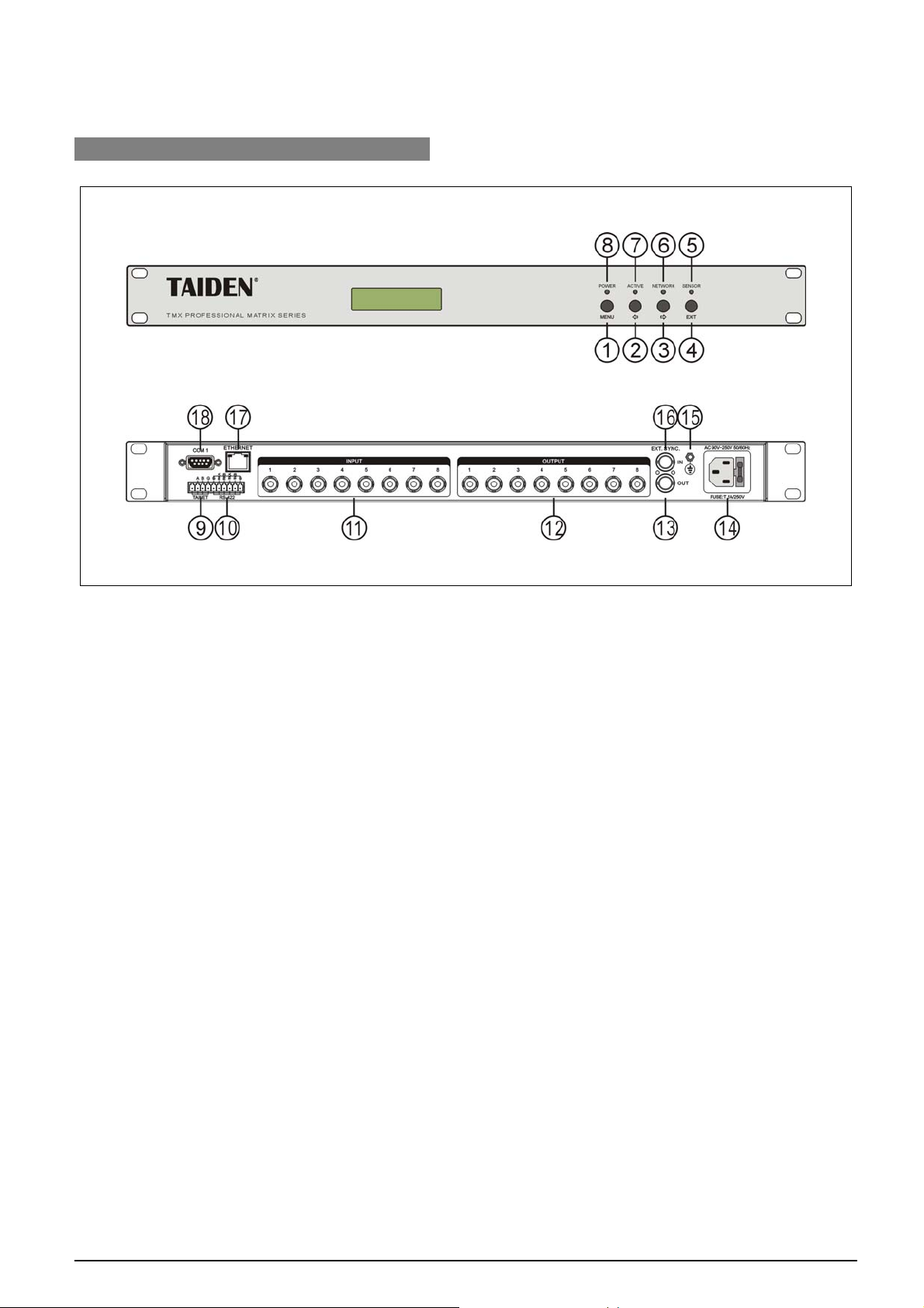
Figure 1.1 Panels of SDI Matrix Switcher
Front panel:
1. “MENU” button
a) If in current state, press “MENU” go to main
menu;
b) If in menu state, press “MENU” go to sub
menu;
c) Select/Deselect in network configuration.
2. “Õ” (Left) button
3. “Ö” (Right) button
4. “Exit” button
Return to previous directory or root.
5. IR receiving window
Receives the IR signals from remote control;
make sure the remote control aims at the
window.
6. “NETWORK” indicator
Indicator flashes if Matrix Switcher is
connected with PC software.
7. “ACTIVE” indicator
Indicator will be turned on if Matrix Switcher
executes switch instructions.
8. “POWER” indicator
Rear panel:
9. TAINET interface
10. RS-422/485 interface
11. Video inputs
12. Video outputs
13. CVBS output / synchronized loop out
14. Power cable interface
15. Grounding point
16. CVBS input / synchronized input
17. RJ45 interface
18. RS-232 communication interface COM1
1
 Loading...